

Page 1
INSTALLATION & OWNER’S
MANUAL
M-INTERFACE GATEWAY
Thank you very much for purchasing our product,
Before using it, please read this manual carefully and keep it for future reference.
Page 2
Installation & Owner's Manual
1
The following contents are stated on the product and the operation manual, including usage,
precautions against personal harm and property loss, and the methods of using the product
correctly and safely.After fully understanding the following contents (identiers and icons), read
the text body and observe the following rules.
CONTENTS PAGE
1. SAFETY INFORMATION
Identier description
Icon description
SAFETY INFORMATION ............................................................................................................................. 1
ACCESSORIES ........................................................................................................................................... 2
M-INTERFACE GATEWAY CONTROLLER INSTALLATION ...................................................................... 3
SYSTEM INTRODUCTION .......................................................................................................................... 8
SETTINGS ................................................................................................................................................... 15
OPERATION INSTRUCTIONS ................................................................................................................... 18
TROUBLE SHOOTING .............................................................................................................................. .28
Identier Meaning
Warning
Means improper handling may lead to personal or severe injury.
Caution
Means improper handling may lead to personal injury or property loss.
[Note]: 1. “Harm” means injury, burn and electric shock which need long-term treatment but need
no hospitalization.
2. “Property loss” means loss of properties and materials.
lcon Meaning
It indicates forbidding. The forbidden subject-matter is indicated in the icon or
by images or characters aside.
It indicates compulsory implementation. The compulsory subject-matter is
indicated in the icon or by images or characters aside.
Page 3
Installation & Owner's Manual
2
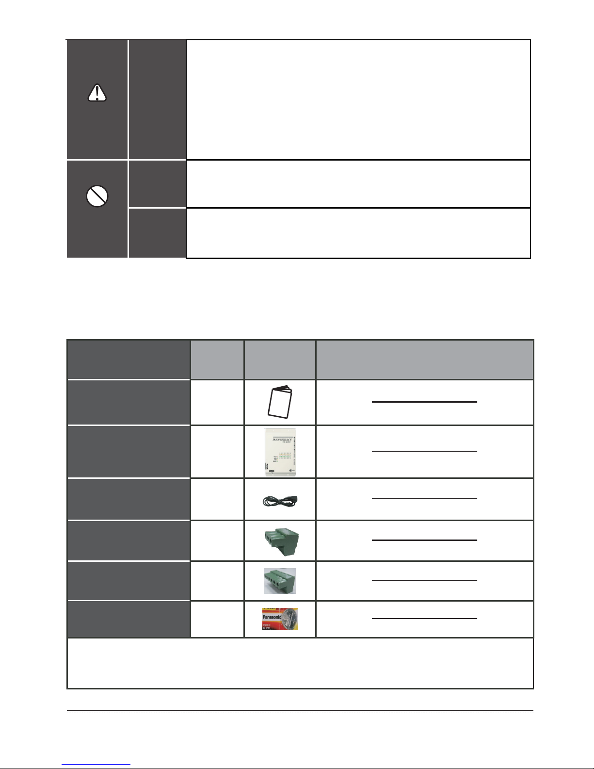
Accessory Name Qty. Shape Purpose
Owner’s & Installation
Manual
1
Control box 1
Power line 1
Communication socket
with 3 terminals
8
Communication socket
with 6 terminals
1
One Button battery
1
Note:
As the product updates, this document will be changed without prior notice.
Table 2-1
2. ACCESSORIES
Warning
Delegate
installation
■
Please entrust the distributor or professionals to install the unit. The
installers must have the relevant know-how. Improper installation
performed by the user without permission may cause re, electric,
shock, personal injury or water leakage.
■ Please do not strike down the M-INTERFACE gateway controller,
otherwise it may lead to abnormal operation, overheating, and
cause electric shock or re etc. damages.
Usage
Warning
Forbid
Do not spray flammable aerosol to the M-INTERFACE gateway
controller directly. Otherwise, re may occur.
Forbid
Do not operate with wet hands or let water enter the M-INTERFACE
gateway controller. Otherwise, electric shock may occur.
Page 4
Installation & Owner's Manual
3
NOTE
CAUTION
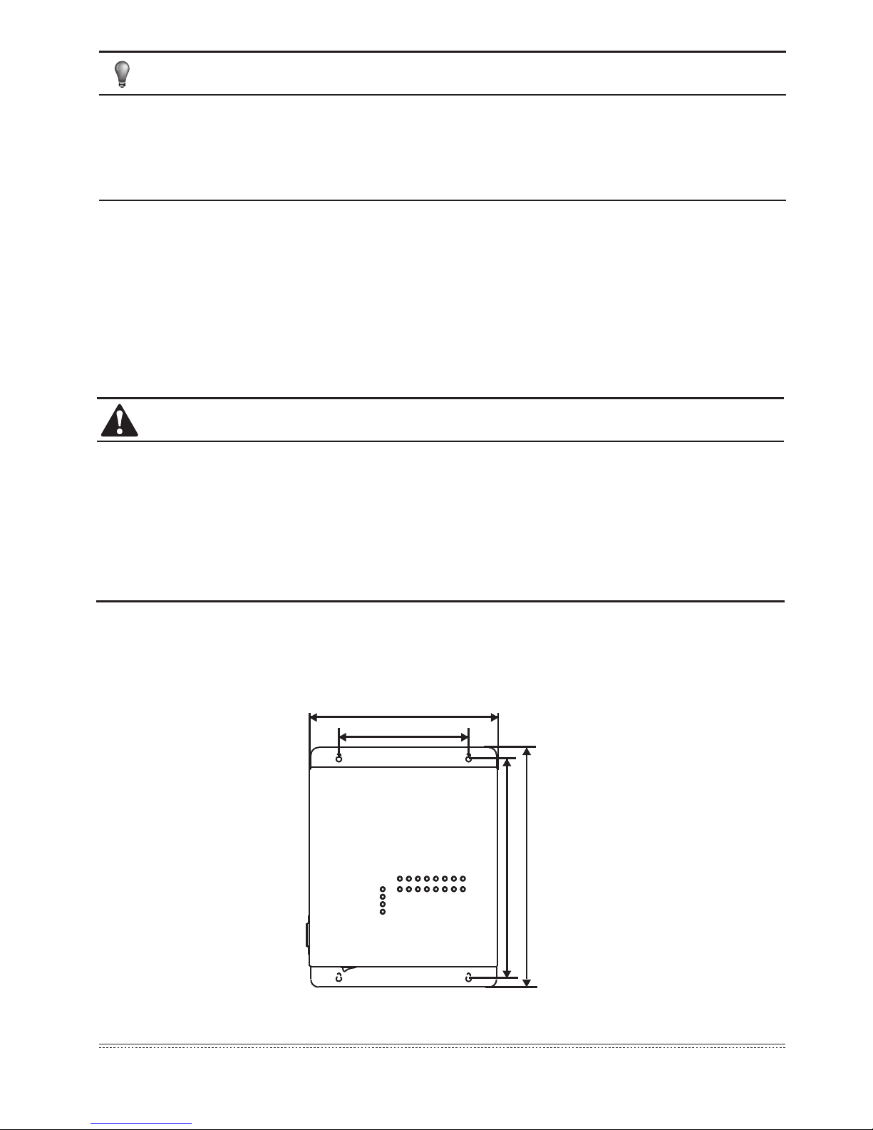
251
173
292.5
319
■
Do not install near a place leak ammble gas easily, otherwise it may cause re;
■
Wiring according to the instruction manual, do not press the terminals, otherwise it may cause
electricity leakage, wire broken, overheat, and re.
Before careful read this manual, do not connect the control system power, and do not do any
installation work, until ensure the preparation work has been done.
3. M-INTERFACE GATEWAY CONTROLLER INSTALLATION
■
Do not install near where has electromagnetic interference or network stations;
■ Do not install near a place has any heat source and steam source or ammable gas source,
which will cause electric leakage easily;
■
Installation should comply with the local rules;
■
Ensure there has enough installation space, for heat dissipation of the community service
network device nearby.
3.1 M-INTERFACE Gateway controller structure
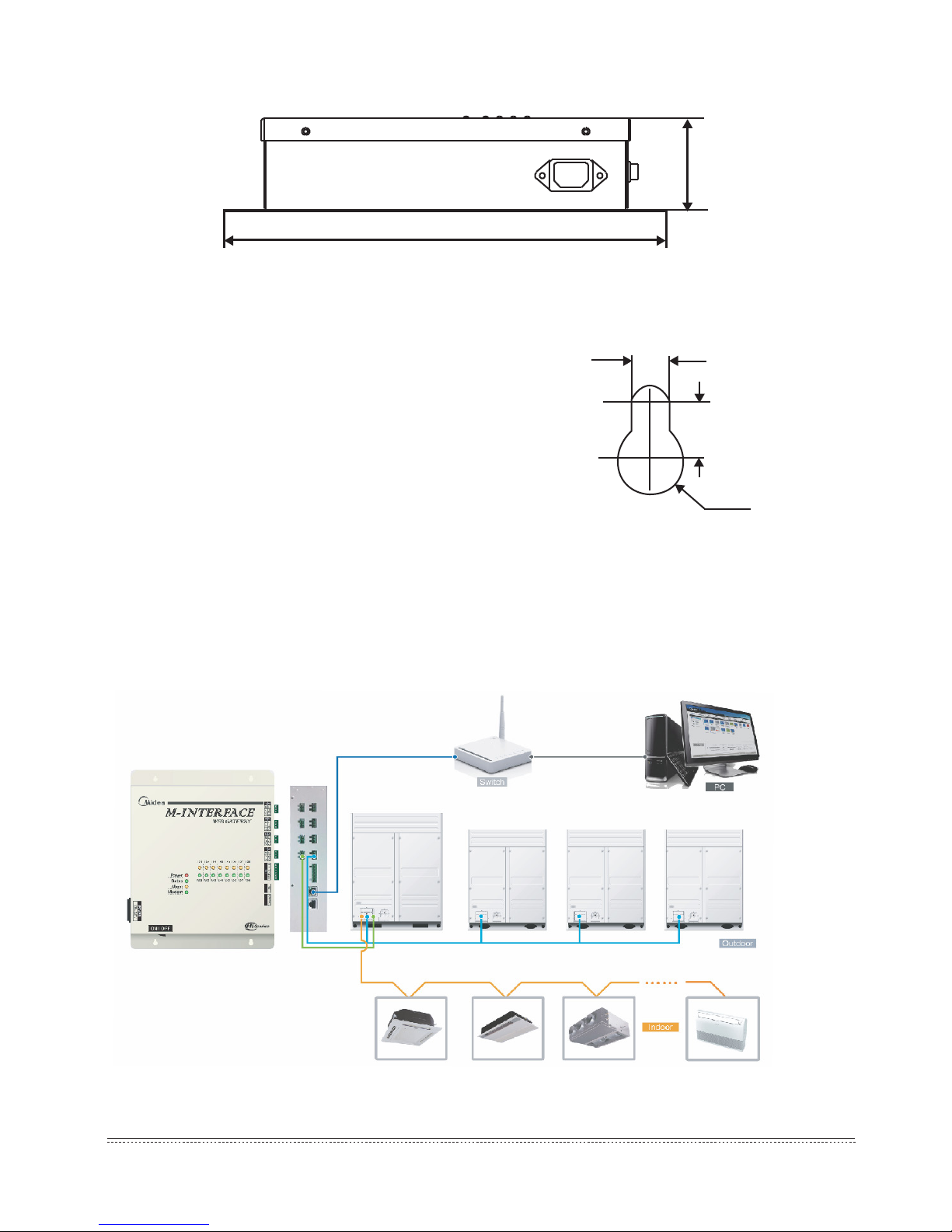
1) Front view of M-INTERFACE gateway controller (Unit: mm)
Fig.3-1
Page 5
Installation & Owner's Manual
4
Fig.3-4
319±1
66.4±1
2) Side view of M-INTERFACE gateway controller (Unit: mm)
3) Detailed drawing of installation holes (Unit: mm)
Installation precautions:
■ Must be installed indoors, guarantee the gateway controller
installation must be higher than the ground 50 cm;
■ Install at a place where should not affect by electromagnetic
wave or dust;
■ Avoid to install at a place where affects by sunshine or heat
source device etc;
■ Avoid to install at a place where has high humidity or can
contact the water;
■ Avoid to install at a place where will produce corrosive or
ammable gas.
■ If suspension installed, make sure put the communication
terminal at the upper side.
Please install according to the above requirements, check
installation environment before installation.
3.2 System framework specication
Fig.3-2
Fig.3-3
4
5.5
R3.5
Page 6
Installation & Owner's Manual
5
NOTE
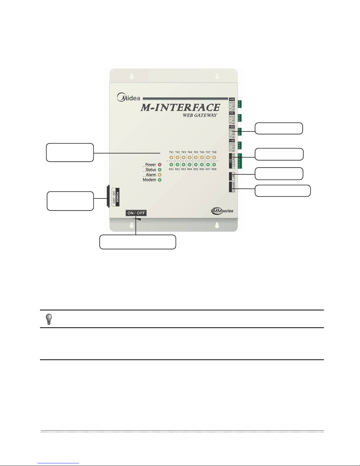
LED indication
lamp
Main power
terminal
Power ON/OFF switch
M-net terminal
I/O terminal
LAN terminal
Console terminal
Fig.3-5
M-INTERFACE gateway controller is used for query and controls the air-conditioning indoor unit,
and transmits the status information of indoor unit to the computer and transmits the controlling and
querying orders sent by the computer to the indoor unit.
1) M-INTERFACE gateway controller indication instructions
M-INTERFACE gateway has 8 M-net terminals, 1 LAN terminal, 8 M-net terminal indication lamps, 4
status display lamps (Power, Status, Alarm, and Modem) and power switch. Connect to the central air-
conditioning system through the M-net terminal, and connect the local area network or Internet network
through LAN terminal. Computer or other similar devices can visit M-INTERFACE WEB through
Brower, and then local or remote control the devices.
■ Install the gateway at a side of M-net communicating bus, do not install it in the middle of the
bus.
■ Use 3-core shielding wire with 0.7mm2~1.0mm2 for wiring, details please refers to professionals.
Page 7
Installation & Owner's Manual
6
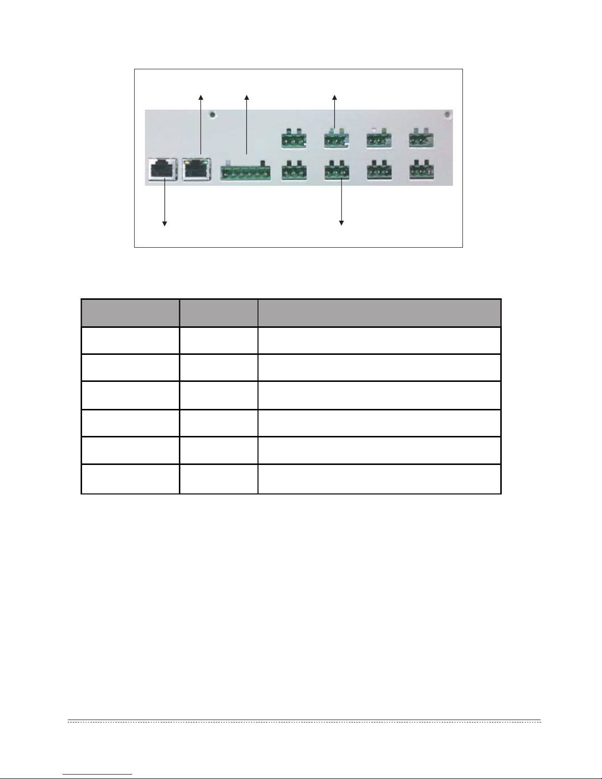
LAN terminal
Console terminal
I/O terminal
1 2 3 4 5 6
XYE
K1K2E
2) Terminal gure
3) LED indication lamp instructions
Fig.3-6
Table.3-1
LED status:
■ Under normal situation, Status lamp will ash with 1HZ frequency, and Alarm lamp will
light off;
■ Under error situation, Status lamp will ash with 1HZ frequency, and Alarm lamp will
ash with 1HZ frequency.
Indication lamp Color Indication lamp instructions
TX1~TX8
Yellow No.1-8 sending terminals indication lamp
RX1~RX8
Green No.1-8 receiving terminals indication lamp
Power Red Power indication lamp
Status
Green Status indication lamp
Alarm Yellow
Alarm indication lamp
Modem
Green Reserve indication lamp
Page 8
Installation & Owner's Manual
7
NOTE
4) Specication parameters of M-INTERFACE gateway controller
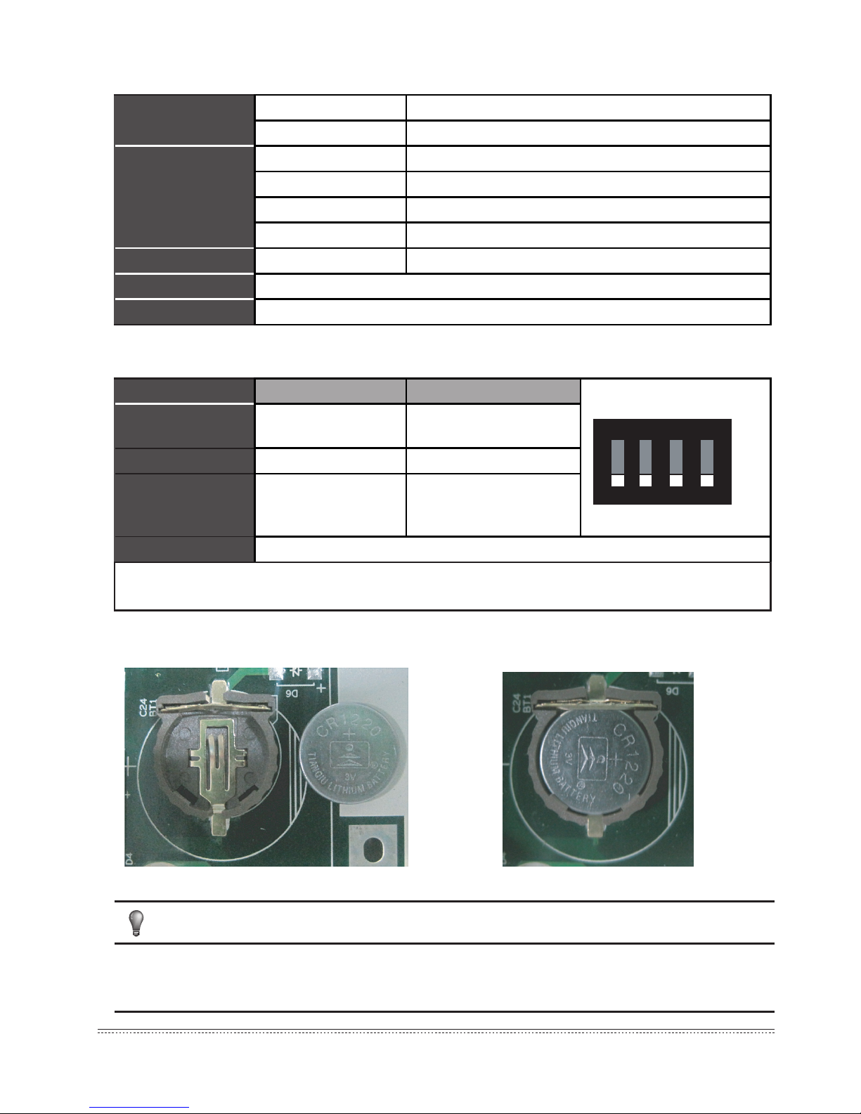
5) Denitions for code switch as follow
:
6) Button battery installation
Fig.3-7
Table.3-2
Table.3-3
Fig.3-8
After adjusted the dial code switch, please install the button batteries (attached in the
accessories package) as the above gure. And synchronize the time refers to 5.2 Time setting.
Power specication
Voltage range Single phase AC 100~240V, 50/60 Hz
Consumed power Max.15W
Using conditions
Voltage uctuation Rated value ±10%
Ambient temp. 0~50
℃
Ambient humidity 25%~90%
Storage temp. -20~60
℃
Capacity Insulated resistance When it is DC 500VM, it will over 50MΩ
Weight 4.4kg
Color of the cover Milky white
Gateway controller On Off (Factory state)
SW1-1
No power
consumption function
power consumption
function
SW1-2 Dial code setting IP WEB setting IP
SW1-3
No power
consumption function
Dial code setting IP
Auto topology
SW1-4 Reserve
Note: Dial code switch needs to take off the cover of control box, and take down four screws
on the cover.
O ND I P
1324
ON
OFF
Page 9
Installation & Owner's Manual
8
Table.3-4
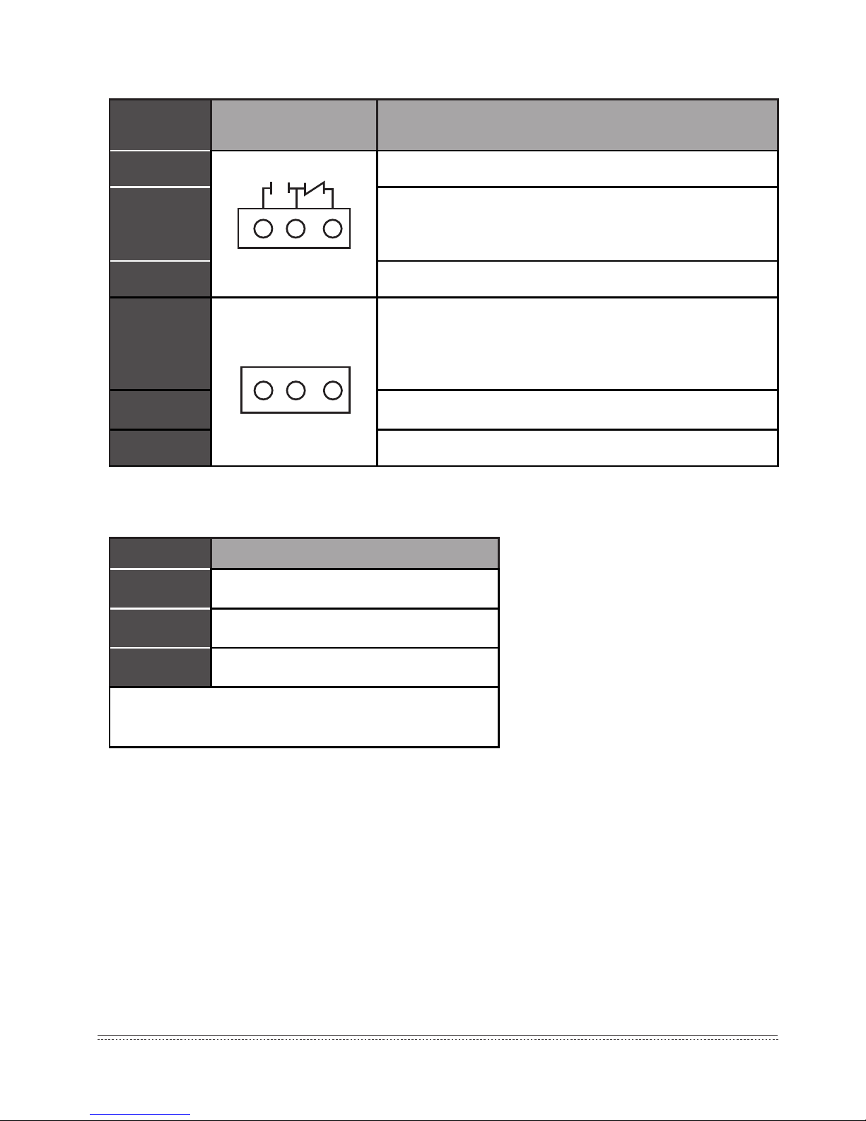
7) IO terminal
8) Uninterruptible power supply (
UPS BK650-CH
optional)
Table.3-5
4. SYSTEM INTRODUCTION
M-INTERFACE is a Central Air-conditioning multi-connected devices’ gateway which based on WEB,
is an important part of Intelligent Manager system (IMM). Connect to Central Air-conditioning devices
through the M-net terminal. It can connect the multi-connected devices through its M-net connector
(M-net connector is XYE communication terminals and K1K2E communication terminals); under the
auto topology mode, it can connect 4 refrigerant systems at most (can insert 256 sets indoor units and
16 sets outdoor units); under the manual topology mode, it can connect16 refrigerant systems at most
(can insert 256 sets indoor units and 64 sets outdoor units). The operation methods of auto topology
and manual topology please refer to IMM TECHNOLOGY MANUAL. The appearance interface of
M-INTERFACE gateway as follow displays:
Requirements
Performance
Capacity 650 VA/400 Watt
Voltage
220V±8%(Battery)
Control signal
50Hz±1Hz(Battery)
Note: When cut off the power please completely close
the computer.
Gateway
controller
Base pin name Function denition
Pin1 Gateway controller error output;
Pin2
When the device operates normally, break off Pin1 and
Pin2, close Pin2 and Pin3; when it is error, close Pin1 and
Pin2, break off Pin2 and Pin3.
Pin3 When it’s powered off, the device still output error.
Pin4
Emergency stop signal, this signal is input signal, and if this
signal is high-level (12~36VDC), then means emergency
stop; if this signal is low-level (0~0.7VDC), then means
normal.
Pin5 Reserve function
Pin6 Ground wire with emergency signal
1 2 3
IN1 IN2 E
4 5 6
Page 10
Installation & Owner's Manual
9
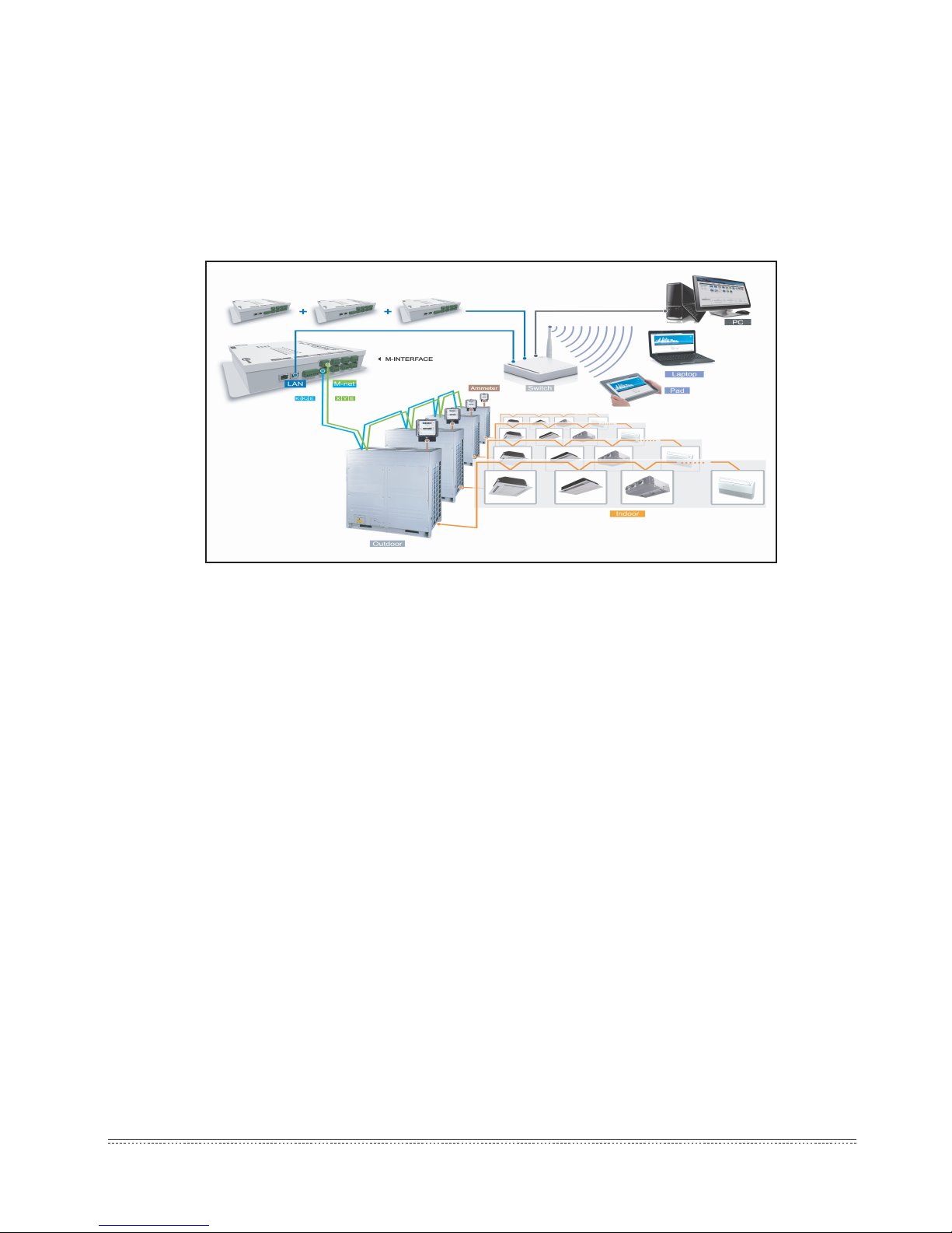
4.1 M-INTERFACE Network
1) M-INTERFACE gateway can connect the local area network or Internet network through LAN
terminal. M-INTERFACE network topology as follows Fig 4-1.
2) M-net terminals are listed to be two rows, 1-4 are XYE terminals, 5-8 are K1K2E terminals.
Computer or other similar devices can visit M-INTERFACE WEB through browser, and then local
or remote control the devices.
4.2 Models which could be inserted
1) Can freely insert all VRF models.
2) If mini VRF will be connected to the project and need power consumption function, the outdoor unit
must be connected to an extra module.
3)Details refer to IMM TECHNOLOGY MANUAL.
4.3 Base on WEB technology
M-INTERFACE is a gateway based on WEB technology, unrelated to computer or similar devices
operation systems. M-INTERFACE insert into network then can browse the WEB page through the
browser of system platform, we suggest using IE (9.0 or above), Firefox (11.0 or above), Chrome (18.0
or above) or Safari (5.1 or above).
4.4 Local network connection
M-INTERFACE gateway can connect to the LAN network through switch. IP address of computer or
similar devices must in the same subnet area as the IP address of M-INTERFACE gateway.
Fig.4-1
Page 11

Installation & Owner's Manual
10
4.4.1 IP conguration
Default IP of gateway is 192.168.100.40, subnet cover code is 255.255.255.0. IP address of computer or similar devices should manual configure the statistic IP and within the range of 192.168.100,
subnet cover code should be 255.255.255.0. If the computer only insert the M-INTERFACE network,
then use the way of configuring single IP; if the computer also inserts the local network beside
M-INTERFACE network, then use the way of conguring several IP. Methods as follow (Take windows
7 system for example).
1) Congure single IP
Open the property dialogue box to congure the IP address and subnet cover code, for example: IP:
192.168.100.44, subnet cover code: 255.255.255.0.
After conguration, click the “OK” button.
2)Congure several IP
Before congure several IP, it needs to congure a statistic IP address, conguring steps as follow:
■ Check the local IP
Open the property dialogue box, as Fig.4-2 display, if the option “Use the following IP
addresses(S)” has been selected, and the interface displayed IP address, that means the local
IP is statistic IP address. Otherwise it is a dynamic IP address, then it needs to configure a
statistic IP address.
■ Congure statistic IP address
Open the “Start” menu, and type “cmd” in the search column, and display the dialogue box as
follow:
Fig.4-2
Page 12

Installation & Owner's Manual
11
Fig.4-3
Type “ipcong” in the above gure, then the interface will display the local dynamic IP address, and it
will write this IP address into the property dialogue box, and nish the statistic IP address conguration,
details please consult the local network administrator.
After the statistic IP address configuration, open the property dialogue box again, select the
“Advanced”, and display the TCP/IP setting dialogue box as follow:
Fig.4-4
Click the “ADD” button under IP address column, and add a IP address with the same network
segment of “192.168.100.40”, such as IP: 192.168.100.101, sub network cover code: 255.255.255.0,
and click “OK” button.
Page 13

Installation & Owner's Manual
12
4.4.2 Local LAN access
If there is a computer or other similar device of same subnet area as M-INTERFACE in LAN, then
type the link address of M-INTERFACE gateway (e.g.: http://192.168.100.40) on the browser address
bar can visit the M-INTERFACE WEB interface to operate the air-conditioning device. The local visit
topology structure as follow display:
Fig.4-5
4.5 Remote network connection
Under the allowable situation, M-INTERFACE gateway can set in the ofce network; the user can
operate the air-conditioning device through the computer or similar devices. Remote insert should base
on some IT technology and help by the network administrator. Three remote insert methods:
1) Statistic IP
Configure public network address statistic IP address for M-INTERFACE gateway, and set it in
the internet; directly visit this public network address then can visit the WEB interface. Ask the local
network operator for the public network address. The public network address insert fee will be charged
by opera-tor, and consider the network safety at the same time.
Fig.4-6
Page 14

Installation & Owner's Manual
13
Fig.4-9
2) Network terminal mapping
If the company has a public network address, then it needs to send a mapping of a terminal in re
wall to M-INTERFACE gateway; when the computer or similar device of outside network visit the
M-INTERFACE, then take http:// public network IP: visit as a terminal. E.g.: http:// 203.208.60.72:6080.
3) VPN visit
■ Router establishing
M-INTERFACE gateway might use a same public IP address with other devices, under the
situation of network cannot send terminal mapping to M-INTERFACE gateway, and then can use
VPN for visiting. As the gure displayed, VPN tunnels establish between routers, and then can
visit WEB interface through VPN tunnels. VPN Server can be established by oneself also can be
rented. Its topology structure as follow display:
■ Computer establishing way
Establish VPN tunnel by computer is a little difficult for general users. Use VPN client-side
software and VPN Server to establish VPN tunnel in the user’s computer, then user can visit WEB
interface through VPN tunnel. VPN client-side software and VPN Server can be achieved by
commercial ways. Its topology structure as follow display:
Fig.4-7
Fig.4-8
Page 15

Installation & Owner's Manual
14
4.6 WEB functions introduction
WEB system has “Device control”, “System mapping”, “Setting”, “Device information” and “Help” etc.
functions.
1) Device monitoring
Offer indoor and outdoor units’ operating details and control the indoor unit.
2) System mapping
Display the entire situation of refrigerant system; include quantities of indoor and outdoor units
in refrigerant system, ammeter quantity and communication quality between single device and
M-INTERFACE gateway.
3) Setting
Offer the centralize controller conguration, time setting, IP setting and User management etc.
functions.
4) Device information
Display and amend detail information of indoor and outdoor devices in air-conditioning system.
5) Help
Offer helping information for user.
Fig.4-10
Page 16

Installation & Owner's Manual
15
5.2 Time setting
Fig.5-2
5. SETTINGS
Do the following settings before using the M-INTERFACE gateway. Only the administrator can
make the following operation.
5.1 M-INTERFACE setting
M-INTERFACE gateway setting as the following display, the setting of baud rate and the energy-
requiring compatibility please refer to IMM TECHNOLOGY MANUAL.
Fig.5-1
Offer M-INTERFACE gateway system time synchronization function, display as follow:
Select the time area, click the “OK” button, and then click the “Synchro time” button for
synchronization. Time synchronization function should be used with caution; details refer to IMM
TECHNOLOGY MANUAL.
Page 17

Installation & Owner's Manual
16
5.3 IP setting
If add the M-INTERFACE into local network, then it needs to reset the M-INTERFACE IP address,
and click “OK ” button after setting. If many M-INTERFACEs in the same network area, then the IP
address could not be repeated.
Fig.5-3
5.4 FTP setting
Set the IP address, terminal, login name (Default: test) and password (Default: 123456) of ftp server.
Click “apply” button after setting.
Fig.5-4
Page 18

Installation & Owner's Manual
17
Fig.5-5
5.5 Multi-pipe setting
Setting contents include: system mode(2:Two-pipe system, 3:Three-pipe system), auto cooling and
heating(only valid for Three-pipe system), temperature different value(ΔT: different value of setting
temperature and room temperature), changing time interval.
Page 19

Installation & Owner's Manual
18
6. OPERATION INSTRUCTIONS
6.1 User login
Type the link address of M-INTERFACE gateway on the browser address (take windows 7 system,
IE for example), then can visit the M-INTERFACE WEB login interface.
Enter the login page, user operates as follow to enter into system:
1) Select user name, type in password;
2) Select the display language;
3) Click [OK] to enter the M-INTERFACE WEB home page;
4) Click [Cancel] to cancel this typing;
If login failed please refers to 7.2 in Appendix.
For safety, every user only can login at one place, if there are repeated login (even the same
computer with different browser), it will force the rst login user back to the login interface. After the
user login, 5 minutes without operations, and re-operate it, the page will automatically back to the login
interface.
Fig.6-1
Page 20

Installation & Owner's Manual
19
Main menu
Submenu
Fig.6-2
6.2 Main interface introduction
WEB home page display as follow:
Information
display
Home page: main menu, submenu and information display. Main menu: display all functions of
system, include “Device monitoring”, “System mapping”, “Setting”, “Device information” and “Help”
etc. functions. Submenu: simple divide the main menu. Information display: display information of a
function.
6.3 Devices monitoring
According to terminal and system to display the operating status of indoor and outdoor units, and
control the indoor unit. Find out the error in system through checking the operating status of indoor and
outdoor units. Detailed display the page will refresh every 10 seconds.
6.3.1 Terminals monitoring
Select the terminal, the page will display corresponding air-conditioning devices under 8 M-net
terminals, and the connected indoor units in 1-4 terminals; it offers checking and amending functions
the operating status of indoor unit.
1) Check the operating status of indoor unit
Fig.6-3
Page 21

Installation & Owner's Manual
20
The operating statuses of indoor unit are cool, heat, fan, OFF, power off, error and lock. Different
operating statuses will has different pictures. Click a single indoor unit, then it will display the operat-
ing status information of this indoor unit on the bottom of page, include ON/OFF status, operating
mode, device name and HP etc. information.
2) Control the operating status of indoor unit
Click the “ ” button in the page, then can control the indoor unit operating status page.
Fig.6-4
Control the air-conditioning indoor unit through single select and multi-select; select one or more airconditioners, set the controlling parameters, include “ON/OFF setting”, “Mode setting”, “Swing setting”,
“Temp setting” and “Fan speed setting”, and then click the “Send” button to send the control order,
and the page will display success or fail information. Check the execution status of order through the
change of the icons on the page.
3) Check the operating status of outdoor unit
Fig.6-5
Select the 5-8 terminals, the page will display the corresponding outdoor unit, and then click the
picture of an outdoor unit, and it will display its operating status include ON/OFF state, operating
mode, fan state, indoor unit quantity, error protection, ammeter readings etc.
Page 22

Installation & Owner's Manual
21
4) Control the operating status of outdoor unit
Priority selecting content of mode include: 5 modes of heating priority, cooling priority, multi-opening
priority, heating only and cooling only, this setting is only valid for water source multi-connected model.
Fig.6-6
6.3.2 System monitoring
Display all the indoor units of refrigerant system as the system way, has the function of checking and
controlling the operating status of indoor unit.
Page 23

Installation & Owner's Manual
22
1) Check the detailed information of indoor unit
Fig.6-7
Select the refrigerant system, the page will display all the indoor unit of the refrigerant system, and
then click the indoor unit and it will display its operating status include ON/OFF state, operating mode,
fan state, indoor unit quantity, error protection, ammeter readings etc.
2) Control the operating status of indoor unit
Fig.6-8
Page 24

Installation & Owner's Manual
23
Click the “ ” button in the page, then can control the indoor unit operating status page. Select one
or more air-conditioners, set the controlling parameters, include “ON/OFF setting”, “Mode setting”,
“Swing setting”, “Temp setting” and “Fan speed setting”, and then click the “Send” button to send the
control order, and the page will display success or fail information. Check the execution status of order
through the change of the icons on the page.
Icon specication:
Table.6-1
Icon Specication Icon Specication
Indoor unit error (RED)
Indoor unit is selected, indoor
ambient temp. is 25℃ (BLUE)
Indoor unit lost connection
(WHITE)
Outdoor unit operates cooling,
outdoor ambient temp. is 25℃
(BLUE)
Indoor unit operates cooling,
indoor ambient temp. is 25℃
(BLUE)
Outdoor unit is OFF, outdoor
ambient temp. is 25℃ (GREY)
Indoor unit operates heating,
indoor ambient temp. is 25℃
(CROCI)
Outdoor unit operates heating,
outdoor ambient temp. is 25℃
(CROCI)
Indoor unit operates fan,
indoor ambient temp. is 25℃
(GREEN)
Outdoor unit error (RED)
Indoor unit is OFF, indoor
ambient temp. is 25℃ (GREY)
Outdoor unit is selected, outdoor
ambient temp. is 25
℃
(BLUE)
Indoor unit is locked, indoor
ambient temp. is 25℃
(GREY)
Outdoor unit lost connection
(WHITE)
Page 25

Installation & Owner's Manual
24
6.4 System mapping
Display the entire situation of refrigerant system, to reect the mapping relationship between the
indoor and outdoor units.
Fig.6-9
Select a single refrigerant system, the page display all the indoor unit pictures of this refrigerant
system, and the bottom of the page display the indoor unit quantity, outdoor unit quantity and ammeter
quantity. Click the single indoor unit to check the communication quality between this device and the
M-INTERFACE.
Characters instruction:
Table.6-2
6.5 Setting
For safety operation of M-INTERFACE, it only offer the “User management” function (Other
functions refer to the IMM TECHNOLOGY MANUAL).
6.5.1 User management
Offer the password changing function.
Indoor unit qty. of
refrigerant system
Calculate all the indoor unit qty. of
refrigerant system
Outdoor unit qty. of
refrigerant system
Calculate all the outdoor unit qty. of
refrigerant system
Outer ammeter qty. of
refrigerant system
Calculate all the ammeter qty. of refrigerant
system
Communication quality
Communication quality between single
device and M-INTERFACE gateway
Page 26

Installation & Owner's Manual
25
Click “OK” button after changing.
6.5.2 Refrigerant system mapping
Output the topology document, the auto topology structure as follow display:
Fig.6-10
Fig.6-11
Page 27

Installation & Owner's Manual
26
6.5.3 Gateway controller status
Display the status information of gateway controller.
Fig.6-12
6.6 Device information
Check the indoor/outdoor device information in the refrigerant system.
6.6.1 Indoor unit information
Select the refrigerant system, click the “Indoor Info”, and the will show up the indoor unit information
display page, as follow:
Fig.6-13
Page 28

Installation & Owner's Manual
27
The display contents include: serial port (terminal no. which inserted into), address, physics location,
sales model, fan power, E-heater power and maintenance status information.
6.6.2 Outdoor unit information
Select the refrigerant system, click the “Outdoor Info”, and the will show up the outdoor unit informa-
tion display page, as follow:
The display contents include: serial port, address, physics location and sales model.
6.7 Help
This function offers error code table for analyze, to help user to check the error of air-conditioner.
This error code may differ from the display contents in the display board, please consult the local
technical support specialist.
6.8 Exit
This function can operate back to the login page, click the “Exit” menu, the system will back to the
login page automatically.
Fig.6-14
Page 29

Installation & Owner's Manual
28
7. TROUBLESHOOTING
7.1 Unable to enter into the login page
Type the IP address of M-INTERFACE gateway in the browser, if it cannot display the login page,
which may be error of network; if it’s needed, ask the IT administer to check the local network. Check
the computer whether stay the same network area with the N-INTERFACE gateway.
7.2 Login failed
When the user is logging, there might be login fail as the following:
1) No password
If the user did not type the password, and clicked “OK”, then it would display as follow:
Type the correct password and then login again.
Fig.7-1
Page 30

Installation & Owner's Manual
29
2) Wrong password
When the password was wrong, it would display as follow:
Type the correct password again.
7.3 No device displayed
If login successfully, and no data display in the home page, then contact the dealer or technicians
to check whether the wiring of M-net communication terminal was correct, and whether the air-
conditioner system has been insert correctly to the M-INTERFACE gateway.
7.4 Control operation failed
When changing the operating status of the indoor unit, there might be prompt message of “Setting
failed”, which means the current operation failed. Contact the dealer or technicians to check whether
the communication between the device and M-net terminal was correct, and also the Ethernet.
7.5 No respond in page
When operating the page and no respond or display “No connection” message, that means the
network communication between computer and M-INTERFACE gateway was broke off, and it needs to
check the computer network card, IP setting, and the switch board, as well as the IP of the M-INTERFACE gateway and LAN terminal network card indication lamp of M-INTERFACE gateway.
Fig.7-2
Page 31

MD12IU-013EW
16110800000047
Page 32

 Loading...