

Midea MGCT-F30W/PN1, MGBT-F60W/PN1, MGCT-D30W/PN1, MGBT-F120W/PN1, MGBT-F180W/PN1 User Manual
Page 1

R410A tropical air-cooled scroll chiller unit 60Hz MCAC-ATSM-2014-09
2
Content
1 General information ....................................................................................... 3
2. Features ......................................................................................................... 4
3. Specification ................................................................................................. 8
4 Dimension .................................................................................................... 14
5 Refrigeration system drawing ..................................................................... 22
6. Piping diagram ............................................................................................ 24
7 Wiring diagram ............................................................................................. 28
8 Electric characteristics ................................................................................ 36
9 Capacity tables ............................................................................................ 38
10 Exploded view ............................................................................................ 46
11 Trouble shooting ........................................................................................ 61
12 Installation .................................................................................................. 76
13 Commissioning ........................................................................................ 101
14 Maintenance ............................................................................................. 102
15 Control system ......................................................................................... 106
Appendix ..................................................................................................... 167
Page 2
MCAC-ATSM-2014-09 R410A tropical air-cooled scroll chiller unit 60Hz
3
1 General information
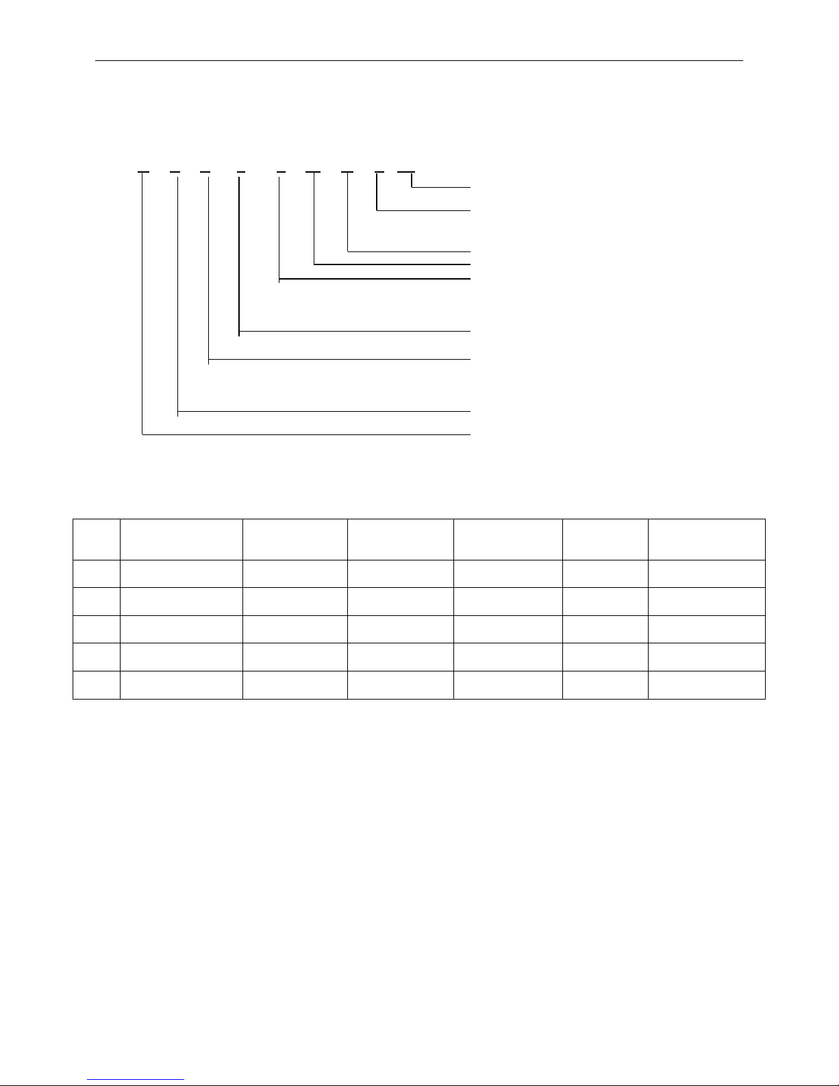
1.1 Nomenclature
M G B T - F 60 W / P N1
1.2 Product list
No
Model
Power supply
Heat exchanger
type
Maximum
combinations
Maximum
capacity(kW)
Wired controller
1
MGCT-F30W/PN1
380V/3Ph/60Hz
Double pipe
16
480
KJRM-120D/BMK-E
2
MGCT-D30W/PN1
380V/3Ph/60Hz
Double pipe
16
480
KJRM-120D/BMK-E
3
MGBT-F60W/PN1
380V/3Ph/60Hz
Shell and tube
16
960
KJRM-120D/BMK-E
4
MGBT-F120W/PN1
380V/3Ph/60Hz
Shell and tube
8
960
KJRM-120D/BMK-E
5
MGBT-F180W/PN1
380V/3Ph/60Hz
Shell and tube
5
900
KJRM-120D/BMK-E
Refrigerant type
N1:R410A Omit for R22
Power Supply
P: 380V, 60Hz, 3Ph
D: 220V, 60Hz, 3Ph
Outdoor Unit
Rated cooling capacity (kW)
The special function code
D: Digital scroll
F: Fixed scroll
V: Inverter system
T: T3 condition
Omit for T1 condition
The heat exchanger type
A: Plate
B: Shell and tube
C: Double pipe
Light chiller system
Midea
Page 3
R410A tropical air-cooled scroll chiller unit 60Hz MCAC-ATSM-2014-09
4
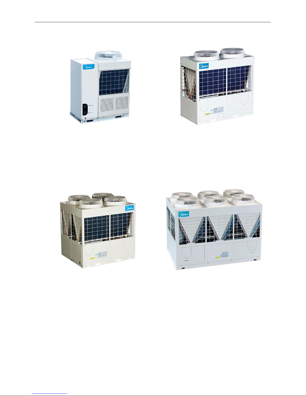
1.3 External appearance
60kW
120kW
180kW
30kW
Page 4
MCAC-ATSM-2014-09 R410A tropical air-cooled scroll chiller unit 60Hz
5
2. Features
1). Wide range of outlet water temperature
Cooling: 5~17˚C (7˚C is default, set in factory), 0~17˚C can be available by switch the S5 on PCB, the
antifreeze must be put into pipeline.
Heating: 40~50˚C (45˚C is default, set in factory), 22~50˚C can be available by switch the address.
Mode
Outlet water temp.
Cooling(S5
address)
Normally(OFF)
5~17℃
Low water temp.(ON)
0~17℃
Heating(S4
address)
Normally(OFF)
40~50℃
Low water temp. (ON)
22~50℃
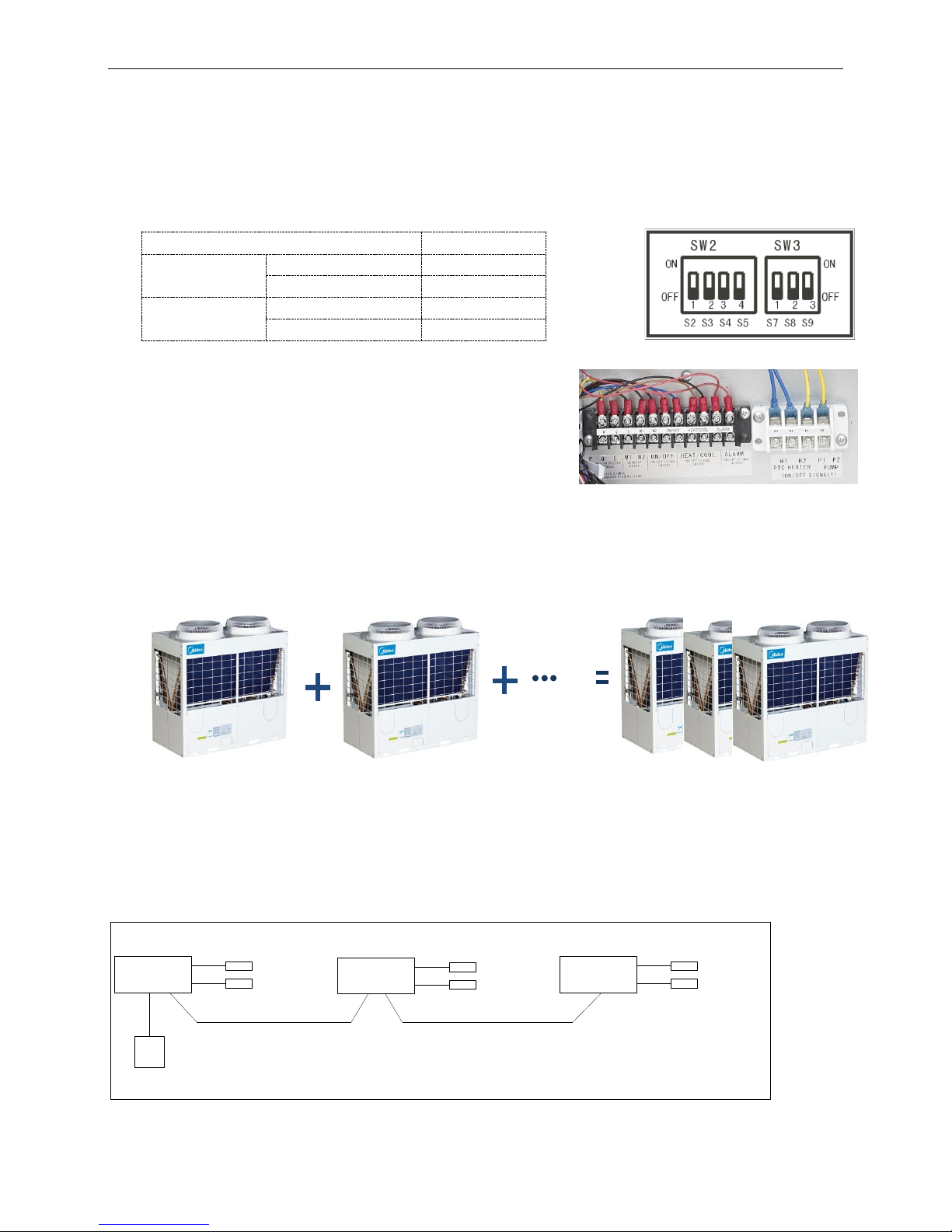
2).Humanized remote control
S7 address on PCB should be switched to ON to realize remote
control, which including remote ON/OFF, remote heating and
cooling mode selection, remote alarm. The customer can simply
and conveniently control the chiller and acquire the running
information on real time in door.
3).Modular design, flexible combination, more convenient for design and installation.
The unit adopts modular design, which can make more units to connect together. The units can be
combined freely, meanwhile every separate module can be operated as main unit, also each module can be
a slave unit with modules combination, more convenient for design and installation.
4).The maximum combination of the system consists of 1 main unit and 15 slave units for
30kW&60kW modules, 1 main unit and 7 slave units for 120kW module, 1 main unit and 4 slave units
for 180kW module.
Easy connection between main unit and slave units.
All the units can be connected together with a wired controller in series type. Using three-core shielded
twisted wire as communication wire.
Wired controller
Three-core shielding
twisted pair
Three-core shielding
twisted pair
Water outlet temp.
Water outlet temp.
Water outlet temp.
Total water outlet temp.
(Just for master unit)
Total water outlet temp.
(Just for master unit)
Total water outlet temp.
(Just for master unit)
5).Environmental care
Ecological R410A refrigerant.
60kW
60kW
960kW
Max 16 modules
Page 5
R410A tropical air-cooled scroll chiller unit 60Hz MCAC-ATSM-2014-09
6
Chlorine-free and environmental friendly refrigerant, zero ozone depletion potential.
High-density refrigerant, therefore, less refrigerant required.
Leak-tight refrigerant circuit, Brazed refrigerant connections for increased leak-tightness.
6) Economical operation
New design adopts electronic expansion valve precise refrigerant control in wider range. Electronic
expansion valve allows operation at lower condensing pressure, adjustment can be made fast linear
response, making the system more stable output, the indoor temperature more uniform, and enhance
human comfortable.
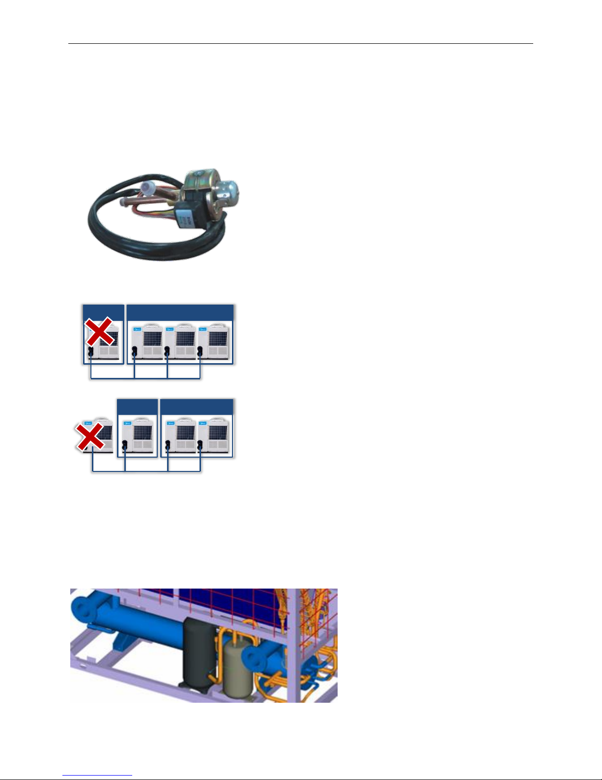
7).Back up function
When unit is failure
If master unit fails, all the units will stop.
If one slave unit fails, this unit will stop but the others will
keep running.
When the master unit fails, any of the slave one can be set
as the master unit by manual setting.
When unit is under protection
If master unit’s protection occurs, this unit will stop but the
others will keep running.
If slave unit’s protection occurs, this unit will stop but the
others will keep running.
( Except PE, P9 protection happen)
8).Strong micro-computer intelligent control and monitor function.
Optimizing the design of system and using varieties of protection devices, to make the system more safe
and reliable.
9). Superior reliability
System will be more reliable with new type efficient heat exchanger. The 30kW module adopts double pipe
heat exchanger, the 60&120&180kW module adopt shell and tube heat exchanger for evaporator.
Shell and tube heat exchanger
Master Slave
Master Slave
Page 6
MCAC-ATSM-2014-09 R410A tropical air-cooled scroll chiller unit 60Hz
7
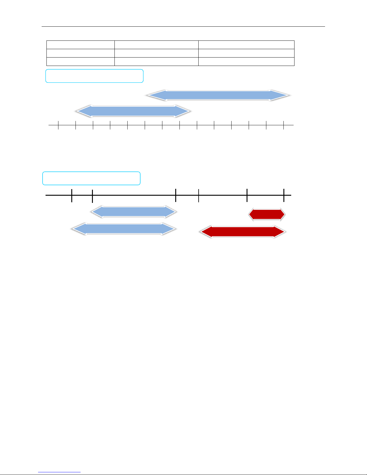
10). Applicable temperature range
Mode
Ambient temperature range
Water outlet temperature range
Cooling
10˚C ~52˚C
0~17˚C(The antifreeze must be added.)
Heating
-10˚C ~24˚C
22˚C ~50˚C
Chilled outlet water temperature can be adjusted by wired controller according to customer’s demand.
-15˚C
Ambient temperature range
-10˚C
-5˚C
0˚C
5˚C
10˚C
15˚C
20˚C
25˚C
30˚C
35˚C
40˚C
45˚C
50˚C
Cooling range
10˚C
52˚C
Heating range
-10˚C
24˚C
Water outlet temperature range
5˚C
17˚C
50˚C
5˚C
17˚C
Heating range
Cooling range
40˚C
22˚C
0˚C
40˚C
50˚C
Cooling range
0˚C
17˚C
Heating range
22˚C
50˚C
Page 7

R410A tropical air-cooled scroll chiller unit 60Hz MCAC-ATSM-2014-09
8
3. Specification
Model
MGCT-F30W/PN1
MGCT-D30W/PN1
Cooling Capacity (*1)
kW
30
30
Btu/h
102,300
102,300
Cooling Capacity (*2)
kW
25.8
25.8
Btu/h
88,030
88,030
Heating Capacity
kW
32
32
Power input
Cooling (*1)
kW
10.0
10.0
Cooling rated current (*1)
A
16.3
16.3
Cooling (*2)
kW
12
12
Cooling rated current (*2)
A
19.56
19.56
Heating
kW
9.8
9.8
Heating rated current
A
16.0
16.0
Power supply
V/Ph/Hz
380/3/60
380/3/60
Power supply
Manual switch A 50
50
Fuse
A
36
36
Max. Input consumption
kW
14.8
13.8
Max. Current
A
25.3
24.2
Compressor
Type
Scroll (fixed speed)
Scroll (Digital +fixed speed)
Brand
Copeland
Copeland
Model
ZP57K3E-TF7-522
ZPD51K5E-TF7-532/
ZP57K3E-TF7-522
Quantity
Pieces
2
1+1
Capacity
Btu/h
58000
50400/58000
Input
kW
5.48
4.71/5.48
Rate load current(RLA)
A
10.1
9.6/10.1
Locked rotor Amp(LRA)
A
94
65.6/94
Refrigerant oil
ml
1685
1242/1685
Refrigerant
Type
R410A
R410A
Refrigerant control
EXV
EXV
Weight
lb
6.834×2
6.834×2
Condenser (Air side)
Air side heat-exchanger type
Fin-coil
Fin-coil
Quantity of fan motor
Pieces
1
1
Air flow volume
×103m3/h
12
12
Fan motor model
YDK550-8B
YDK550-8B
Fan motor rated current
A
4
4
Fan motor input
kW
0.85
0.85
Evaporator (Water
side)
Water side heat-exchanger type
Double pipe
Double pipe
Water resistance loss
kPa
60
60
Water inlet/outlet pipeline
inside normal diameter
inch
1-1/2”
1-1/2”
Water flow volume
m3/h
5.2
5.2
Max. Pressure
MPa
1
1
Water pipe connection type
Flexible joint
Flexible joint
Dimension
Net(W×H×D)
inch
59.61×73.43×33.11
59.61×73.43×33.11
Packing size(W×H×D)
inch
62.6×81.3×39.17
62.6×81.3×39.17
Page 8

MCAC-ATSM-2014-09 R410A tropical air-cooled scroll chiller unit 60Hz
9
Weight
Net weight
lb
837.8
837.8
Gross weight
lb
881.8
881.8
Connection wiring
Power wire
mm2×No.
10×4+6 ×1
10×4+6 ×1
Signal wire
mm2×No.
0.75×3-core with shielding
Control type
Wired controller
Safety protection device
1) Protection for over-high discharge pressure
2) Protection for over-low suction pressure
3) Power supply phase sequence protection
4) Anti-freezing protection in cooling mode
5) Anti-freezing protection in winter
6) Protection for compressor over current
7) Protection for compressor overload
8) Outlet and inlet water temperature difference protection
9) Compressor discharge temperature protection
10) Water flow cut-off protection
11) Sensor malfunction protection
12) Low-temperature protection of shell and tube heat
exchanger.
Noise level
dB(A)
67
Operation water temperature
℃
Cooling:0~17(Less than 5℃ must add antifreeze.)
Heating:22~50
Ambient temperature
℃
Cooling:10~52 Heating:-10~21
Note:
Please refer to the water flow volume in the above table strictly to design and install.
Specifications are based on the following conditions:
Cooling : (*1)chilled water inlet/outlet: 12℃ / 7℃, and outdoor ambient temp. of 35°C DB.
(*2) chilled water inlet/outlet: 12℃ / 7℃, and outdoor ambient temp. of 46°C DB.
Heating : warm water inlet/outlet: 40℃ / 45℃, and outdoor ambient temp. 7°C DB/6°C WB.
Water side fouling factor: 0.086m2·℃/kW.
1m away in open field (sound pressure).
Page 9

R410A tropical air-cooled scroll chiller unit 60Hz MCAC-ATSM-2014-09
10
Model
MGBT-F60W/PN1
MGBT-F120W/PN1
Cooling Capacity (*1)
kW
60
120
Btu/h
204,700
409,400
Cooling Capacity (*2)
kW
51.6
103.2
Btu/h
176,100
352,100
Heating Capacity
kW
65
130
Power input
Cooling (*1)
kW
19.7
39.4
Cooling rated current (*1)
A
63
126
Cooling (*2)
kW
23.64
47.28
Cooling rated current (*2)
A
75.6
151.2
Heating
kW
19.9
39.8
Heating rated current
A
65.5
130
Power supply
V/Ph/Hz
380/3/60
380/3/60
Power supply
Manual switch A 125
200
Fuse
A
100
150
Max. Input consumption
kW
26.9
51.44
Max. Current
A
48.7
95
Compressor
Type
Scroll (fixed speed)
Scroll (fixed speed)
Brand
Danfoss
Danfoss
Model
SH105A9ALC
SH105A9ALC
Quantity
Pieces
2
4
Capacity
Btu/h
97060
97060
Input
kW
9.9
9.9
Rate load current(RLA)
A
21.4
21.4
Locked rotor Amp(LRA)
A
124
124
Refrigerant oil
ml
3300
3300
Refrigerant
Type
R410A
R410A
Refrigerant control
EXV+ capillary
EXV+ capillary
Weight
lb
14.33×2
14.33×4
Condenser (Air
side)
Air side heat-exchanger type
Fin-coil
Fin-coil
Quantity of fan motor
Pieces
2
4
Air flow volume
×103m3/h
24
48
Fan motor model
YS650-8C
YS650-8C
Fan motor rated current
A
2.1×2
2.1×4
Fan motor input
kW
1.03×2
1.03×4
Evaporator (Water
side)
Water side heat-exchanger type
Shell and tube
Shell and tube
Water resistance loss
kPa
15
25
Water inlet/outlet pipeline
inside normal diameter
inch
4”
2-1/2”
Water flow volume
m3/h
10.3
20.6
Max. Pressure
MPa
1
1
Water pipe connection type
Flexible joint
Flexible joint
Dimension
Net(W×H×D)
inch
78.74×74.02×35.43
78.74×82.28×66.34
Packing size(W×H×D)
inch
82.28×82.48×38.78
81.89×88.19×69.09
Weight
Net weight
lb
1,300.727
2,601.455
Gross weight
lb
1,388.889
2,711.64
Connection wiring
Power wire
mm2×No
16×4+10 ×1
35×3+16 ×2
Page 10
MCAC-ATSM-2014-09 R410A tropical air-cooled scroll chiller unit 60Hz
11
Signal wire
mm2×No
0.75×3-core with shielding
0.75×3-core with shielding
Control type
Wired controller
Wired controller
Safety protection device
1) Protection for over-high discharge pressure
2) Protection for over-low suction pressure
3) Power supply phase sequence protection
4) Anti-freezing protection in cooling mode
5) Anti-freezing protection in winter
6) Protection for compressor over current
7) Protection for compressor overload
8) Outlet and inlet water temperature difference protection
9) Compressor discharge temperature protection
10) Water flow cut-off protection
11) Sensor malfunction protection
12) Low-temperature protection of shell and tube heat
exchanger.
Noise level
dB(A)
67
70
Operation water temperature
℃
Cooling:0~17(Less than 5℃ must add antifreeze.)
Heating:22~50
Ambient temperature
℃
Cooling:10~52 Heating:-10~21
Note:
Please refer to the water flow volume in the above table strictly to design and install.
Specifications are based on the following conditions:
Cooling : (*1)chilled water inlet/outlet: 12℃ / 7℃, and outdoor ambient temp. of 35°C DB.
(*2) chilled water inlet/outlet: 12℃ / 7℃, and outdoor ambient temp. of 46°C DB.
Heating : warm water inlet/outlet: 40℃ / 45℃, and outdoor ambient temp. 7°C DB/6°C WB.
Water side fouling factor: 0.086m2·℃/kW.
1m away in open field (sound pressure).
Page 11

R410A tropical air-cooled scroll chiller unit 60Hz MCAC-ATSM-2014-09
12
Model
MGBT-F180W/PN1
Cooling Capacity (*1)
kW
180
Btu/h
614,100
Cooling Capacity (*2)
kW
154.8
Btu/h
528,200
Heating Capacity
kW
195
Power input
Cooling (*1)
kW
59.1
Cooling rated current (*1)
A
189
Cooling (*2)
kW
70.92
Cooling rated current (*2) A 226.8
Heating
kW
59.7
Heating rated current A 196.5
Power supply
V/Ph/Hz
380/3/60
Power supply
Manual switch
A
350
Fuse
A
300
Max. Input consumption
kW
76.5
Max. Current
A
140
Compressor
Type
Scroll (fixed speed)
Brand
Danfoss
Model
SH105A9ALC
Quantity
Pieces
6
Capacity
Btu/h
97060
Input
kW
9.9
Rate load current(RLA) A 21.4
Locked rotor Amp(LRA) A 124
Refrigerant oil
ml
3300
Refrigerant
Type
R410A
Refrigerant control
EXV+ capillary
Weight
lb
14.33×6
Condenser (Air side)
Air side heat-exchanger type
Fin-coil
Quantity of fan motor
Pieces
6
Air flow volume
×103m3/h
72
Fan motor model
YS650-8C
Fan motor rated current A 2.1×6
Fan motor input
kW
1.03×6
Evaporator
(Water side)
Water side heat-exchanger type
Shell and tube
Water resistance loss
kPa
30
Water inlet/outlet pipeline
inside normal diameter
inch
3”
Water flow volume
m3/h
31
Max. Pressure
MPa 1 Water pipe connection type
Flexible joint
Dimension
Net(W×H×D)
inch
112.21×83.07×78.74
Packing size(W×H×D)
inch
117.32×88.98×84.06
Weight
Net weight
lb
3,813.93
Gross weight
lb
3,924.16
Connection wiring
Power wire
mm2×No.
70×3+35 ×2
Page 12

MCAC-ATSM-2014-09 R410A tropical air-cooled scroll chiller unit 60Hz
13
Signal wire
mm2×No.
0.75×3-core with shielding
Control type
Wired controller
Safety protection device
12) Protection for over-high discharge pressure
13) Protection for over-low suction pressure
14) Power supply phase sequence protection
15) Anti-freezing protection in cooling mode
16) Anti-freezing protection in winter
17) Protection for compressor over current
18) Protection for compressor overload
19) Outlet and inlet water temperature difference
protection
20) Compressor discharge temperature protection
21) Water flow cut-off protection
22) Sensor malfunction protection
12) Low-temperature protection of shell and tube
heat exchanger.
Noise level
dB(A)
74
Operation water temperature
℃
Cooling:0~17(Less than 5℃ must add
antifreeze.)
Heating:22~50
Ambient temperature
℃
Cooling:10~52 Heating:-10~24
Note:
Please refer to the water flow volume in the above table strictly to design and install.
Specifications are based on the following conditions:
Cooling : (*1)chilled water inlet/outlet: 12℃ / 7℃, and outdoor ambient temp. of 35°C DB.
(*2) chilled water inlet/outlet: 12℃ / 7℃, and outdoor ambient temp. of 46°C DB.
Heating : warm water inlet/outlet: 40℃ / 45℃, and outdoor ambient temp. 7°C DB/6°C WB.
Water side fouling factor: 0.086m
2
·℃/kW.
Page 13
R410A tropical air-cooled scroll chiller unit 60Hz MCAC-ATSM-2014-09
14
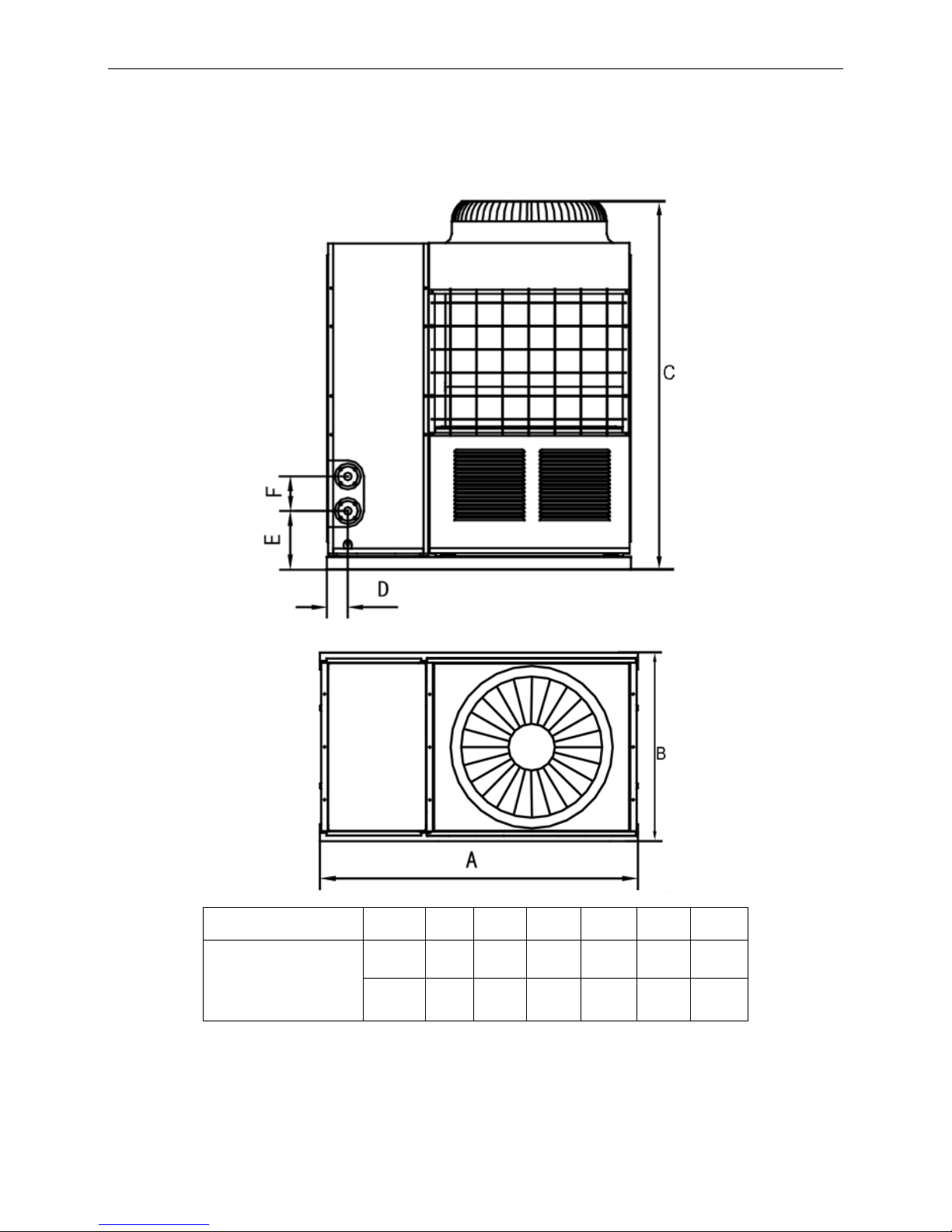
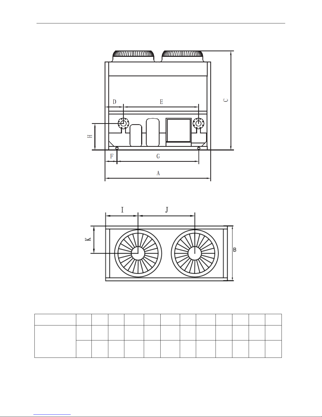
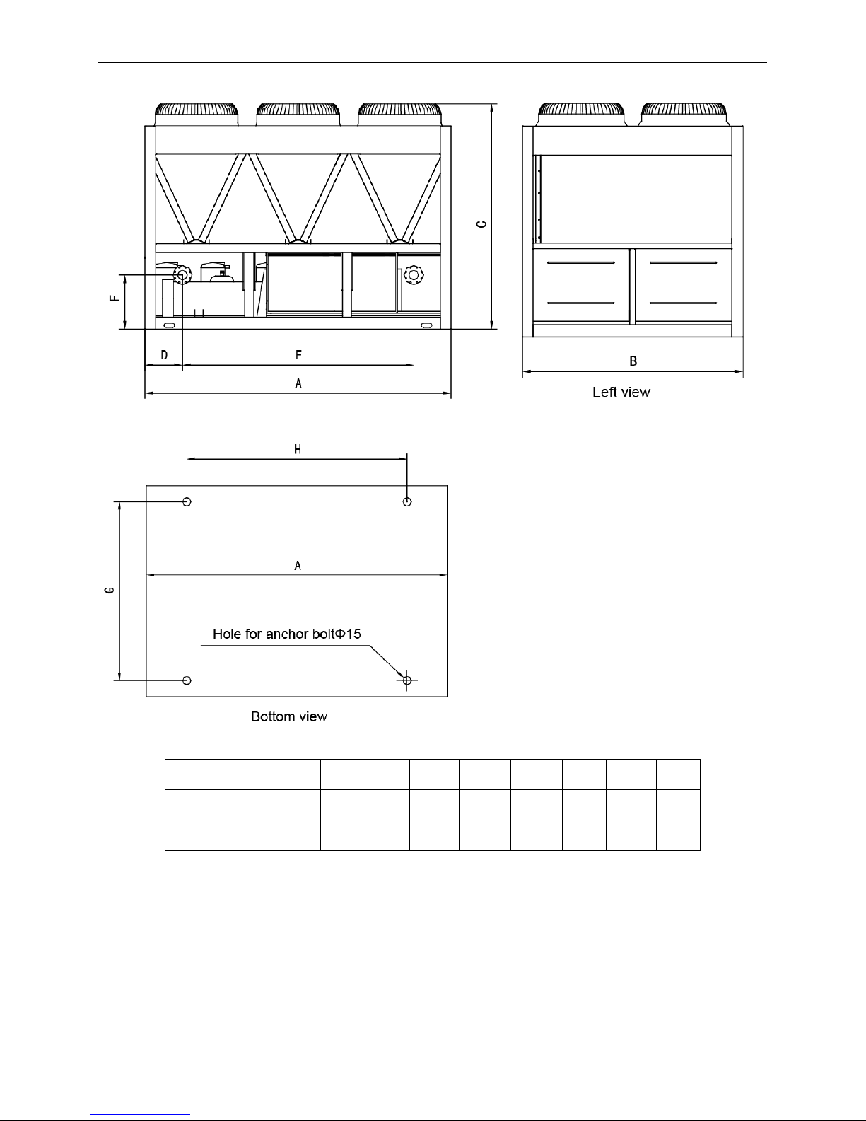
4 Dimension
30kW module
Model
Unit
A B C D E
F
MGCT-F30W/PN1
MGCT-D30W/PN1
mm
1514
841
1865
115
315
172
inch
59.6
33.11
73.43
4.53
12.4
6.77
Page 14
MCAC-ATSM-2014-09 R410A tropical air-cooled scroll chiller unit 60Hz
15
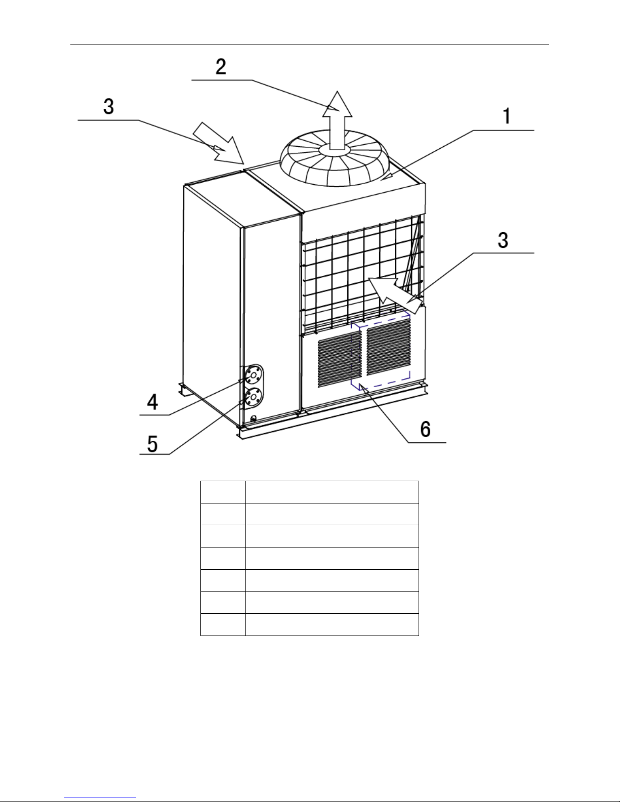
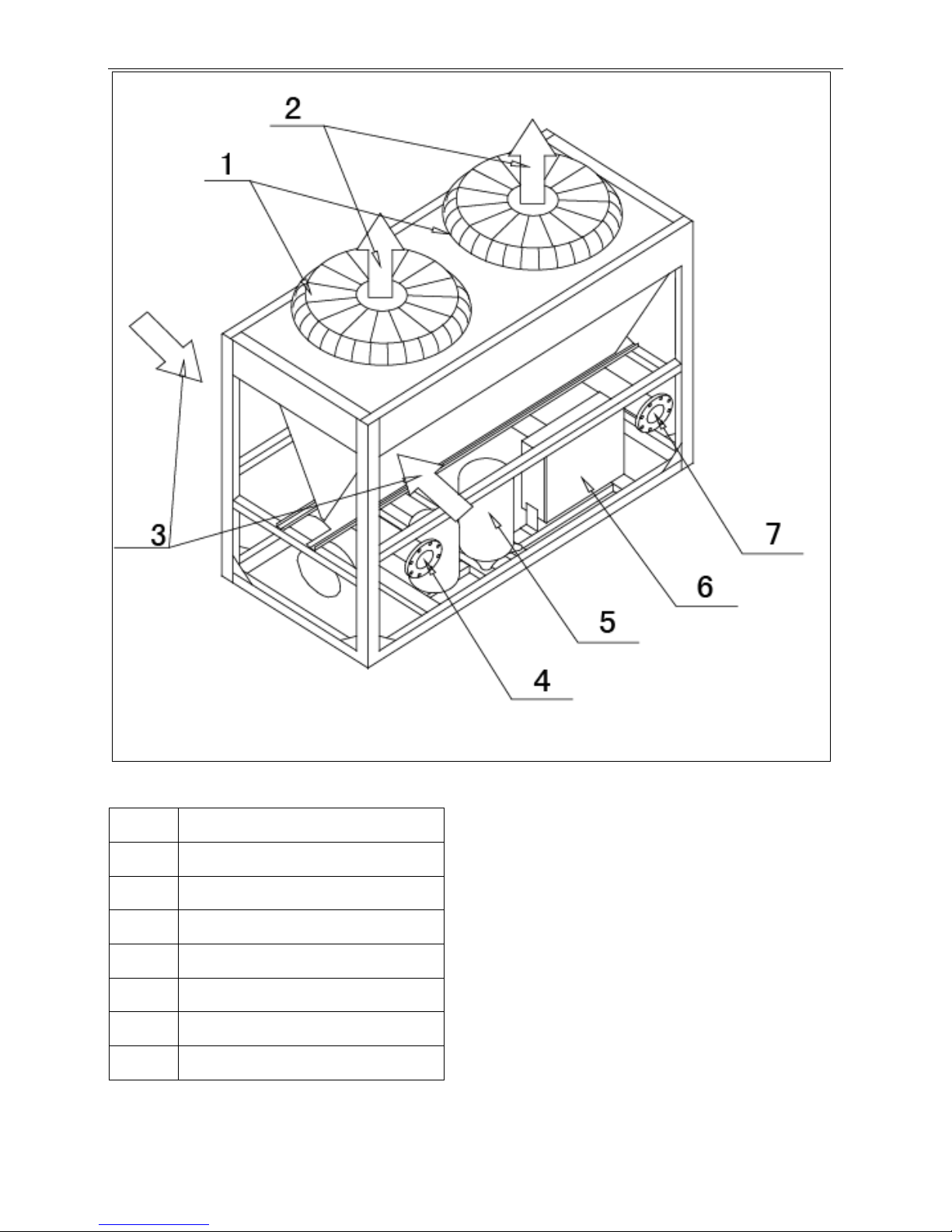
No.
Name
1
Top cover
2
Air outlet
3
Air inlet
4
Water outlet
5
Water inlet
6
Electric control box
Page 15
R410A tropical air-cooled scroll chiller unit 60Hz MCAC-ATSM-2014-09
16
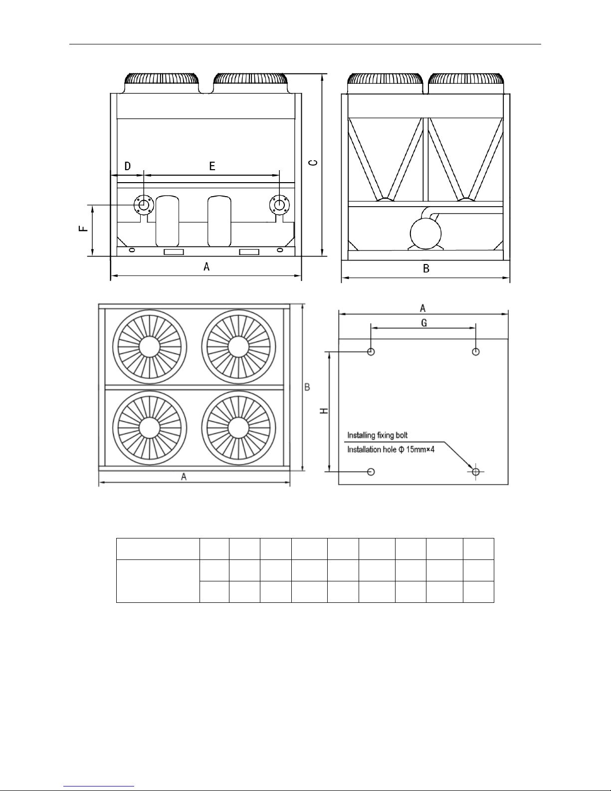
60kW module
Front view
Top view
Model
Unit
A B C D E F G H I J K
MGBT-F60W/PN1
mm
2000
900
1880
350
1420
225
1500
506
530
930
450
inch
78.74
35.4
74
13.78
55.91
8.86
59.06
19.92
20.87
36.61
17.72
Page 16
MCAC-ATSM-2014-09 R410A tropical air-cooled scroll chiller unit 60Hz
17
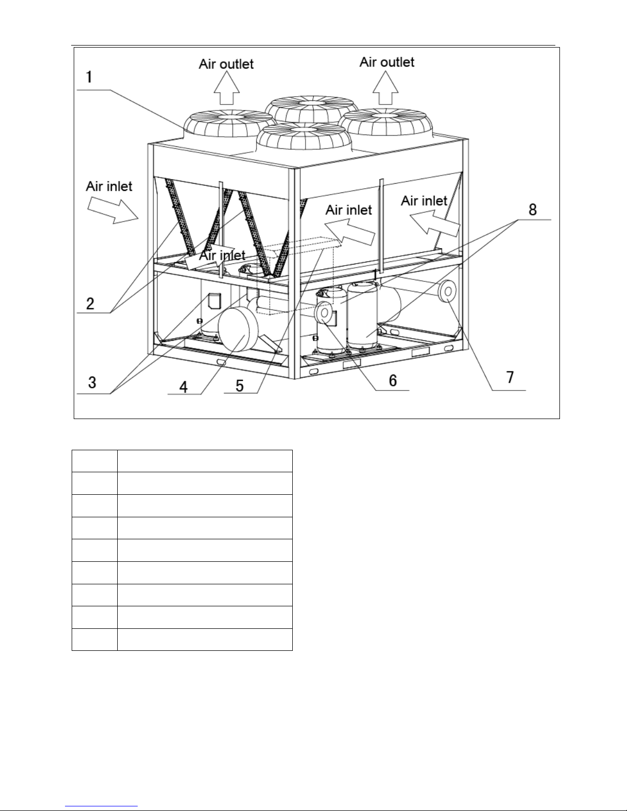
No.
Name
1
Top cover
2
Air outlet
3
Air inlet
4
Water outlet
5
Compressor
6
Electric control box
7
Water inlet
Page 17
R410A tropical air-cooled scroll chiller unit 60Hz MCAC-ATSM-2014-09
18
120kW module
Front view Side view
Top view Anchor hole
Model
Unit
A B C D E F G
H
MGBT-F120W/PN1
mm
2000
1685
2080
355
1420
506
1550
1586
inch
78.74
66.34
81.89
13.98
55.91
19.92
61.02
62.44
Page 18
MCAC-ATSM-2014-09 R410A tropical air-cooled scroll chiller unit 60Hz
19
No.
Name
1
Top cover
2
Condenser
3
Compressor
4
Evaporator
5
Electric control box air inlet
6
Water outlet
7
Water inlet
8
Compressor
Page 19
R410A tropical air-cooled scroll chiller unit 60Hz MCAC-ATSM-2014-09
20
180kW module
Model
unit A B C D E F G H
MGBT-F180W/PN1
mm
2850
2000
2110
3470
2156
506
1888
2388
inch
112.2
78.74
83.07
136.61
84.88
19.92
74.33
94.02
Page 20

MCAC-ATSM-2014-09 R410A tropical air-cooled scroll chiller unit 60Hz
21
No.
Name
1
Top cover
2
Compressor
3
Evaporator
4
Water outlet
5
Electric control box
6
Water inlet
7
Condenser
Page 21
R410A tropical air-cooled scroll chiller unit 60Hz MCAC-ATSM-2014-09
22
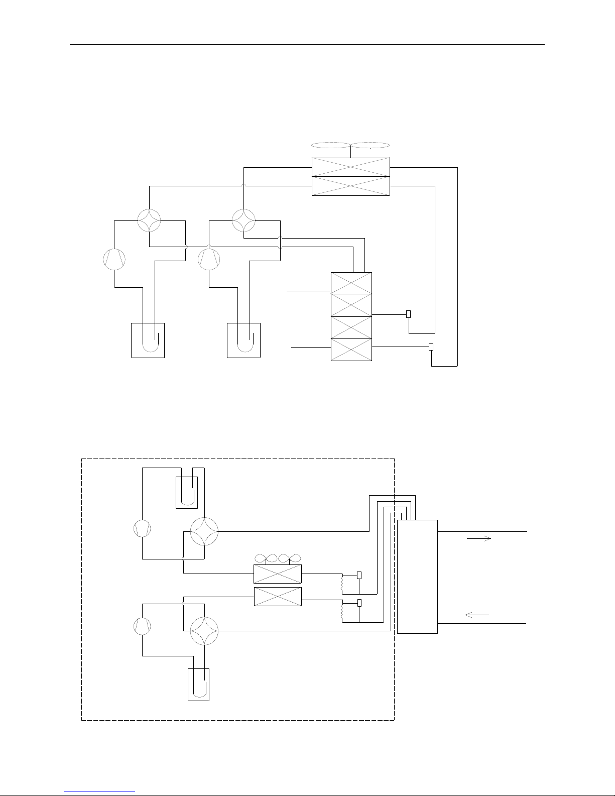
5 Refrigeration system drawing
5.1 30kW module refrigeration system sketch drawing
Each module has two compressors with one separate unit, one double pipe evaporator for two refrigerant
systems.
Compressor A
Compressor B
Low pressure cylinder A
Low pressure cylinder B
4-way valve A
4-way valve B
Condenser
Evaporator
(Double-pipe heat exchanger)
Fan
Water outlet
Water inlet
EXV
EXV
5.2 60kW module refrigeration system sketch drawing
Each module has two compressors with one separate unit, one shell and tube evaporator for two refrigerant
systems.
Dry type evaporator
Condenser
Water flow direction
Compressor B
low pressure cylinder B
4-Way valve A
Fan A
EXV
Capillary
EXV
4"
Capillary
Fan B
4-Way valve B
Compressor A
low pressure cylinder A
Fan
Page 22
MCAC-ATSM-2014-09 R410A tropical air-cooled scroll chiller unit 60Hz
23
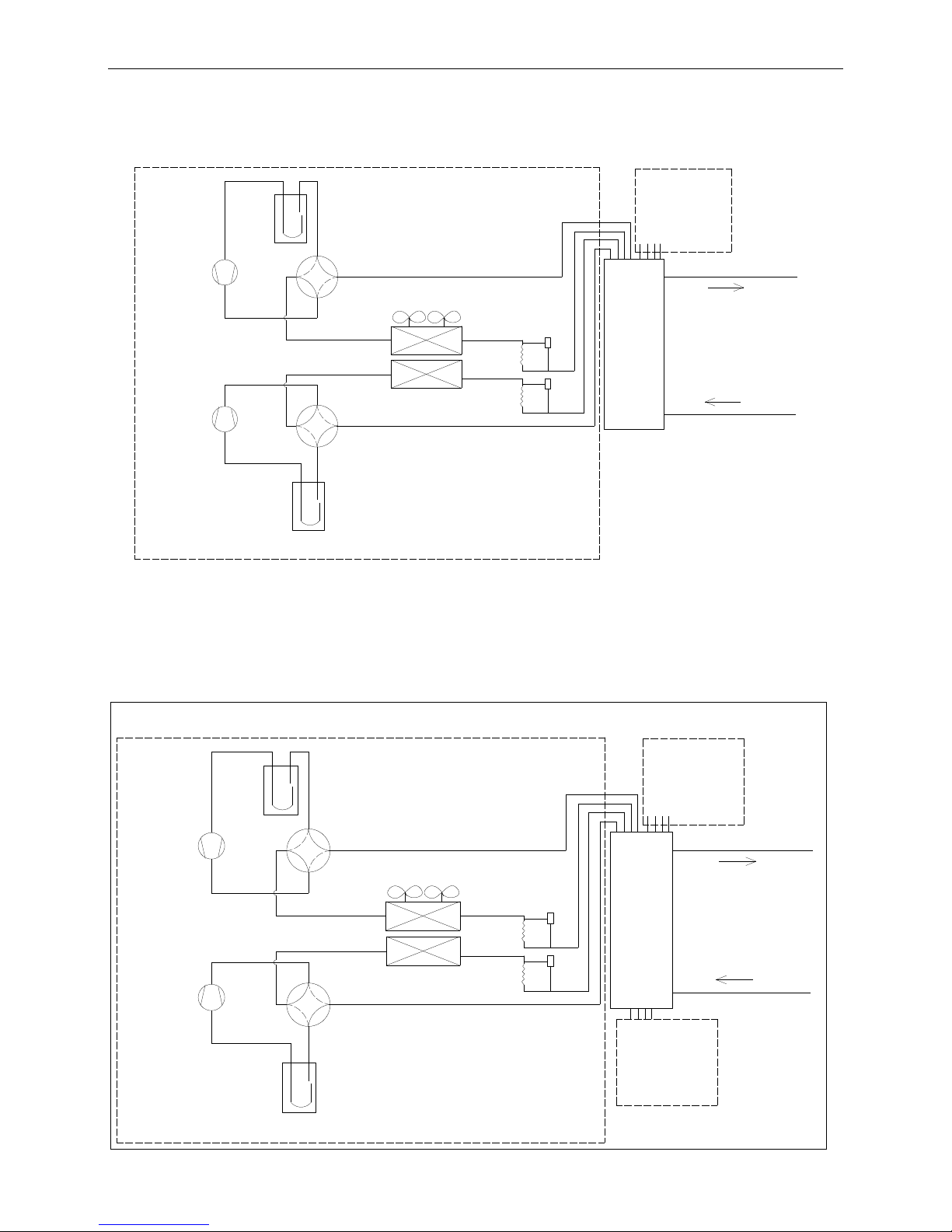
5.3 120kW module refrigeration system sketch drawing
Each module has four compressors with two separate units, one shell and tube evaporator for four
refrigerant systems.
Dry type evaporator
Condenser
Water flow direction
Compressor B
low pressure cylinder B
4-Way valve A
Fan A
EXV
Capillary
EXV
2-1/2"
Unit 2
Capillary
Fan B
4-Way valve B
Compressor A
low pressure cylinder A
Unit 1
5.4 180kW module refrigeration system sketch drawing
Each module has six compressors with three separate units, one shell and tube evaporator for six refrigerant
systems.
Dry type evaporator
Condenser
Water flow direction
Compressor B
low pressure cylinder B
4-Way valve A
Fan A
EXV
Capillary
EXV
3"
Unit 2
Unit 3
Capillary
Fan B
4-Way valve B
Compressor A
low pressure cylinder A
Unit 1
Page 23
R410A tropical air-cooled scroll chiller unit 60Hz MCAC-ATSM-2014-09
24
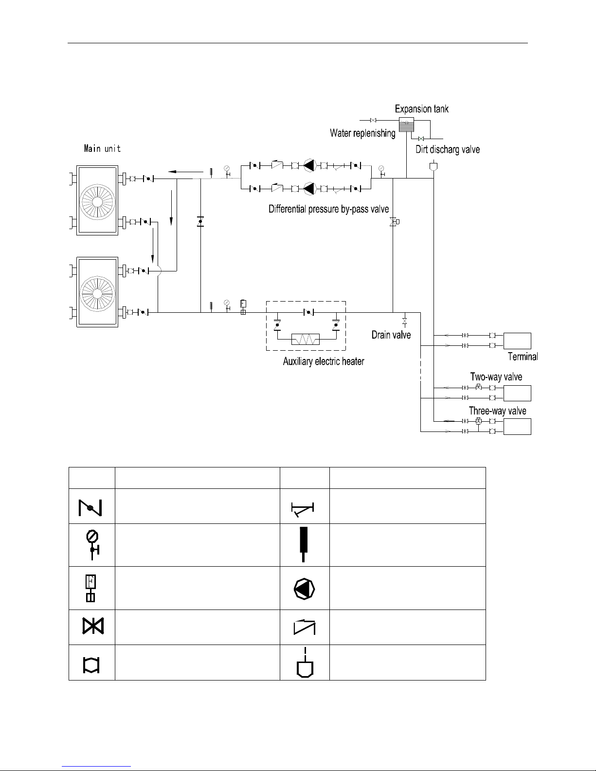
6. Piping diagram
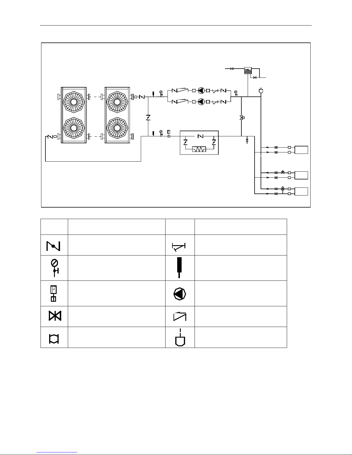
6.1 30kW module water pipeline sketch drawing
The table below describes the symbols.
Symbol
Symbol explanation
Symbol
Symbol explanation
Stop valve
Y-shaped filter
Pressure gauge
Thermometer
Water flow switch
Circulating pump
Gate valve
Check valve
Flexible joint
Automatic discharge valve
Page 24
MCAC-ATSM-2014-09 R410A tropical air-cooled scroll chiller unit 60Hz
25
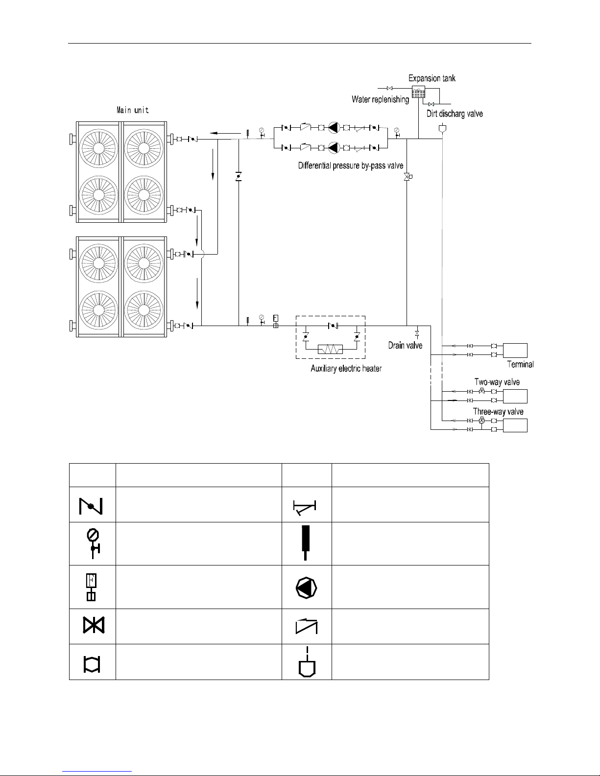
6.2 60kW module water pipeline sketch drawing
The table below describes the symbols.
Symbol
Symbol explanation
Symbol
Symbol explanation
Stop valve
Y-shaped filter
Pressure gauge
Thermometer
Water flow switch
Circulating pump
Gate valve
Check valve
Flexible joint
Automatic discharge valve
Main unit
Expansion tank
Water replenishing
Dirt discharge valve
Differential pressure by-pass valve
Drain valve
Two-way valve
Three-way valve
Terminal
Auxiliary electric heater
Page 25
R410A tropical air-cooled scroll chiller unit 60Hz MCAC-ATSM-2014-09
26
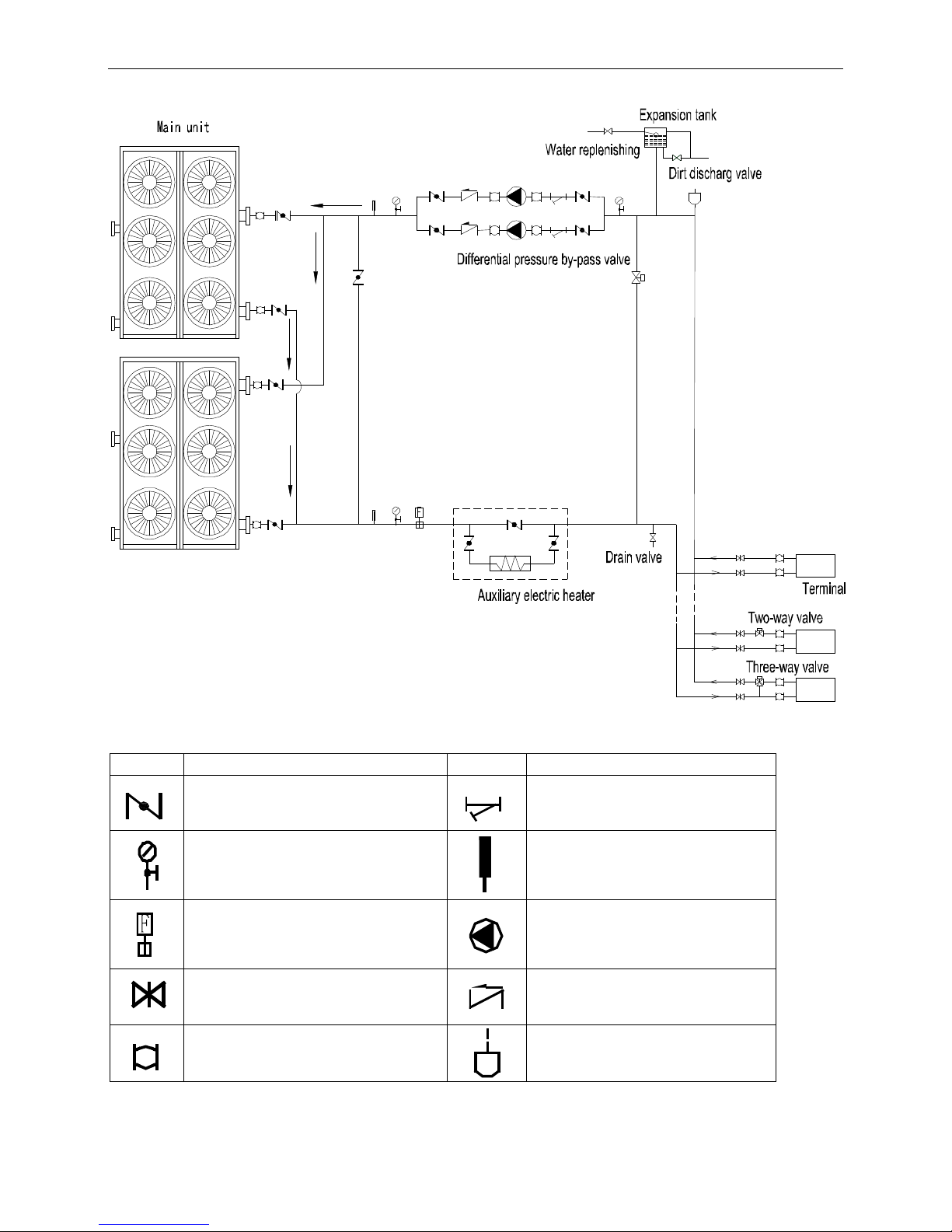
6.3 120kW module water pipeline sketch drawing
The table below describes the symbols.
Symbol
Symbol explanation
Symbol
Symbol explanation
Stop valve
Y-shaped filter
Pressure gauge
Thermometer
Water flow switch
Circulating pump
Gate valve
Check valve
Flexible joint
Automatic discharge valve
Page 26
MCAC-ATSM-2014-09 R410A tropical air-cooled scroll chiller unit 60Hz
27
6.4 180kW module water pipeline sketch drawing
The table below describes the symbols.
Symbol
Symbol explanation
Symbol
Symbol explanation
Stop valve
Y-shaped filter
Pressure gauge
Thermometer
Water flow switch
Circulating pump
Gate valve
Check valve
Flexible joint
Automatic discharge valve
Page 27
R410A tropical air-cooled scroll chiller unit 60Hz MCAC-ATSM-2014-09
28
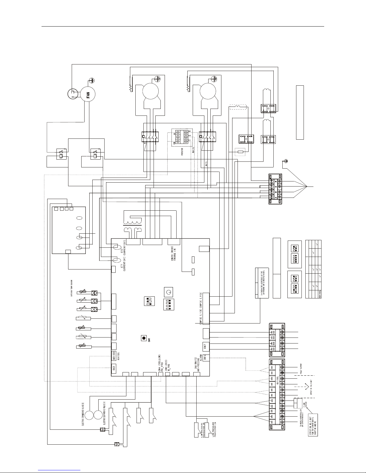
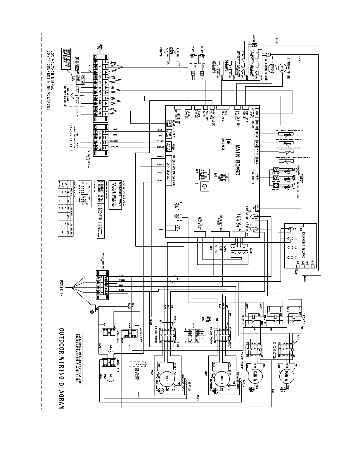
7 Wiring diagram
7.1 Wiring diagram
30kW module
XP8
XP7
XS8
XS7
T
3
B
T3A
COMP A
2
5
21
3
6
22
4
T3(W)
A1
A2
T2(V)
T1(U)
HEAT_A
QP
(E)
PMV(B)
RED BLACK
CH EC K
CN 18 ( WH I T E)
PO WE R
PW M
CN 17
CN 11 (BL AC K)
CN 24
PU MP
HE AT
CN 1(W HI TE )
PM V (A )
CN 2(R ED)
PM V( B )
CN 5
H& L_ P RO
CN 6
CO M (I )
CN 25
CO M( O )
CN 10
CN 21 CN 14
PMV(A)
CN 19(W H IT E)
TR AN S O UT
FA N_ A
CN 30
FA N_ B
CN 31
COMP B
2
1
5213
6
22
4
T3(W)
A1
A2
T2(V)
T1(U)
RED
PUR PL E
BLA CK
BLU E
RE D
WH IT E
S1
T3 A T3 B T 4
XT 7
XT 6
W1 W 2
HE A T_ B
TR AN S
ON /O F F
AL AR M
BL AC K
RED
RE D
BLUE
BLACK
XS9
XP9
T
4
WHITE
R
E
D
B
L
U
E
K1(A)
H_PRO(A)
K1(B)
H_PRO(B)
L_PRO(1A)
L_PRO(1B)
BLACK
L1 L2
CN 7
CN 8
BLA CK
S2 S3
ON
SW 2
S4 S5
OFF
S7 S8
ON
SW 3
S9
OFF
ORA NG E
L_PRO(2B)
L_PRO(2A)
CN 15
CN 5
CN 6
L3 L4
CN 4
CN 22
CN 26
ON /O FFP Q E
BLA CK
XT 5
BLACK
BLACK
BLACK
5V
Y&G
RED
WHITE
KM1
HIGH
BLA C K
BL UE
RE LA Y
FAN C A P
WHITE
BLUE
RED
RED
CON DENS ER
TEM P B
CON DENS ER
TE MP A
HIG H PR ES SU RE
PRO TE CT OR B
LOW P RE SSU RE
PRO TE CT OR 1B
LOW P RE SSU RE
PRO TE CTO R 1A
HIG H PR ES SU RE
PRO TE CT OR A
TEM P PR OTE CT OR
SWI TC H A
TEM P PR OTE CT OR
SWI TC H B
ORANGE
RED
PURPLE
YELLOW
CURRENT(B2)
CURRENT(A2)
RED
PURPLE
CO M
NC
FLO W
SWT IC H
PU MP
(EFF ECT ON NO.0 MODU LE)
(ON / OFF SI GN AL !)
LO W VO L T A G E S I G NAL
DO N' T C O N N E C T H IGH VO LT A G E !
PRO VI DE
BY US ER
PRO VI DE
BY US ER
(O N / O FF S I G N AL ! )
11- WA Y
TER MI NA L
XT2
BLU E
BLU E
GRA Y
Y
E
L
L
O
W
B
L
A
C
K
G
R
A
Y
B
L
A
C
K
R
E
D
B
R
O
W
N
R
E
D
R
E
D
G
R
A
Y
(YE LLOW)(R ED )
BL UE
BL UE
YEL L OW
(B LU E)
B
L
U
E
MAIN BOARD
CURRENT BOARD
ORA N GE
BLUE
PU RP LE
RE D
PWM PRESSURE
RELIF VALVE
BLUE
Y&G
MIDD LE
WIRE J OINT
MIDD LE
WIRE J OINT
MID DLE
WIR E JOINT
S.V(A)
4-VALVE A
4- WA Y TE RM IN AL
XT 1
POW E R I N
SW3
S1
16- WAY D AIL S WIT CH FU NCT IO N
DAI L SWI TCH A DDR ESS
1 2 3
ON
3 4
SW2
1 2
OFF
S2 ON:COOL ONLY OFF:R&C
S3 ON:DIGITAL OFF:FIXED
S4 ON:H-EEPROM OFF:NORMAL
S5 ON:C-EEPROM OFF:NORMAL
S7 ON:REMOTE CONTROL OFF:WIRE CONTROL
S8 ON:LOW TEMP.MODE OFF:NORMAL
S9 ON:30KW OFF:65/130/200/260K W
S2 S3 S4 S5 S7 S8 S9
SW2/SW3 FUCTION DEFINATION
ON
OFF
DEFAULT SETTING
REMOTE TURN OFF
OFF
ON/OFF
S7
ON
REMOTE FUCTION SETTING
REMOTE COOL
ON OFF
REMOTE HEAT
ON OFF
SW 3
1 2 3
ON
3 4
SW 2
1 2
OFF
S2 S3 S4 S5 S7 S8 S9
ON
OFF
DIGITAL
FIXED
BLACK
R
E
D
B
L
U
E
AC C ON T AC TO R
AC C O NT A CT OR COM PRES SOR A
COM PRES SOR B
BLUE
RED
WHI TE
Y&G
CR AN KC AS E HEAT ER
Y&G
BLACK
BLUE
RED
WHI TEBLACK
IN- LE T WAT ER T EM P SEN SO R
ANT I- FR EE ZIN G TE MP SE NS OR
TOT AL O UT- LE T WA TE R TEM P
UNI T OU T- LE T WAT ER T EMP
MA R K:NO RM A L MO D UL E S DO N 'T I NC L UD E
BR O KE N L IN E AN D T HE IR JO IN T W IR E S
OUT D O O R W I R ING DIAG R A M
BROWN
BROWN
BLACK BLACK
BLU E
BRO WN
BLACK
RE D
BLUE
WH IT E
S.V(B)
4-VALVE B
CR AN KC AS E HEAT ER
BRO WN
BRO WN
BRO WN
BRO WN
BRO WN
H2 P 1 P 2H1
4- WA Y T ER MI NA L
XT 3
YE LL OW
KM2
RE LA Y
LOW
BLU E
(WH IT E)
BLU E
YE LL OW
YE LL OW
202090191107
HEA T
RES
Page 28
MCAC-ATSM-2014-09 R410A tropical air-cooled scroll chiller unit 60Hz
29
60kW module
Page 29
R410A tropical air-cooled scroll chiller unit 60Hz MCAC-ATSM-2014-09
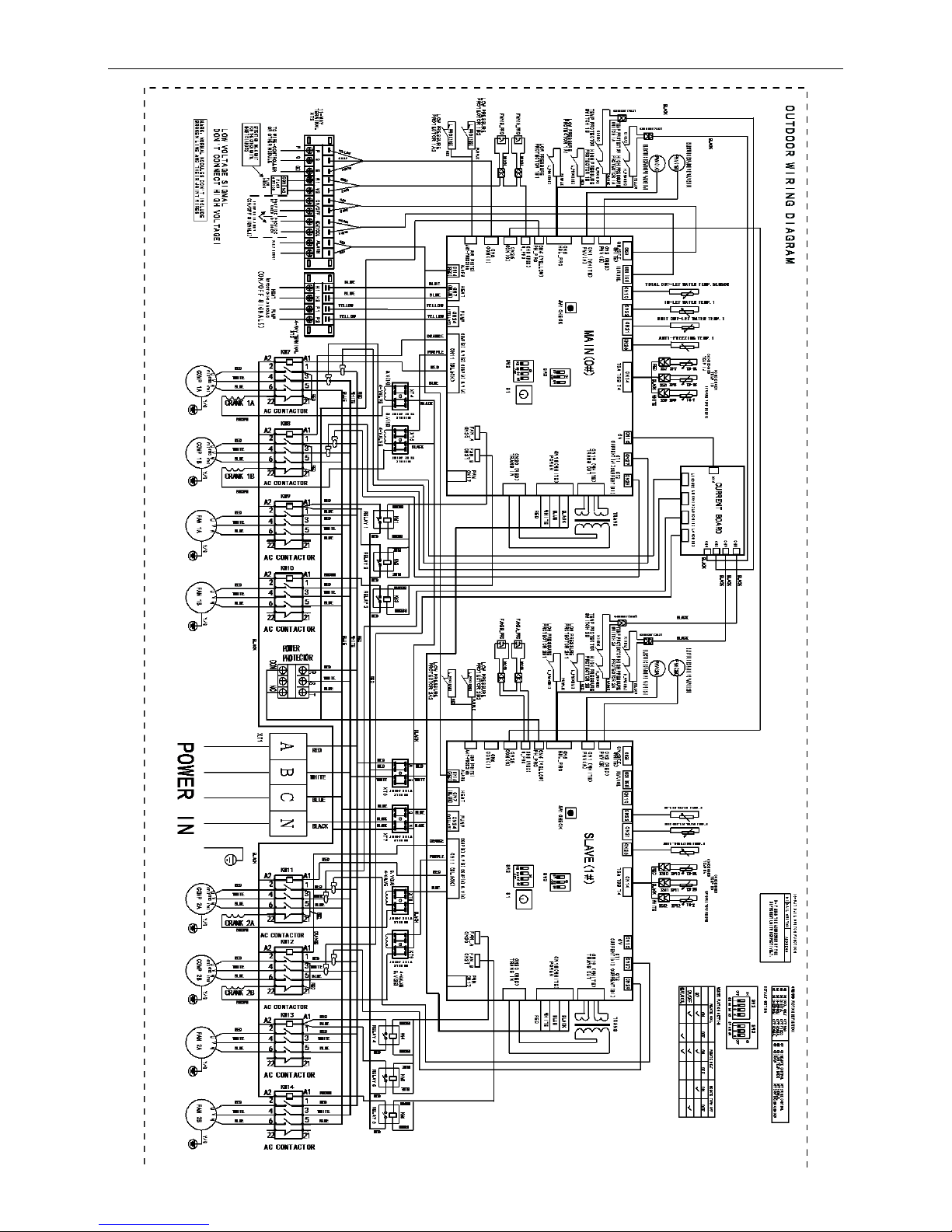
30
120kW module
Page 30
MCAC-ATSM-2014-09 R410A tropical air-cooled scroll chiller unit 60Hz
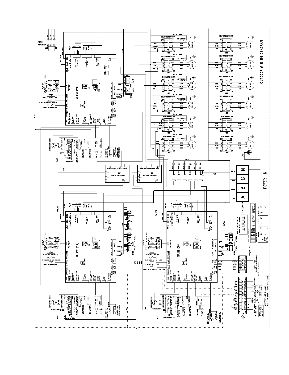
31
180kW module
Page 31

R410A tropical air-cooled scroll chiller unit 60Hz MCAC-ATSM-2014-09
32
7.2 Networking communication schematic
30kW module
Page 32

MCAC-ATSM-2014-09 R410A tropical air-cooled scroll chiller unit 60Hz
33
60kW module
Page 33

R410A tropical air-cooled scroll chiller unit 60Hz MCAC-ATSM-2014-09
34
120kW module
Page 34

MCAC-ATSM-2014-09 R410A tropical air-cooled scroll chiller unit 60Hz
35
180kW module
Page 35

R410A tropical air-cooled scroll chiller unit 60Hz MCAC-ATSM-2014-09
36
8 Electric characteristics
Model
Outdoor Unit
Power Supply
Compressor
OFM
Hz
Phase
Voltage
Min.
Max.
TOCA
MFA
LRA
RLA
KW
FLA
MGCT-F30W/PN1
60 3 380
342
418
28.5
36
94(×2)
10.1(×2)
0.85
4
MGCT-D30W/PN1
60 3 380
342
418
28.5
36
65.6/94
9.6/10.1
0.85
4
MGBT-F60W/PN1
60 3 380
342
418
55.6
70
124(×2)
21.4(×2)
1.03(×2)
2.1(×2)
MGBT-F120W/PN1
60 3 380
342
418
222.4
260
124(×4)
21.4 (×4)
1.03 (×4)
2.1(×4)
MGBT-F180W/PN1
60 3 380
342
418
180
300
124(×6)
21.4(×6)
1.03 (×6)
2.1(×6)
Remark:
TOCA: Total Over-current Amps. (A)
MFA: Max. Fuse Amps. (A)
LRA: Locked Rotor Amps. (A)
RLA: Rated Load Amps. (A)
OFM: Outdoor Fan Motor.
KW: Rated Motor Input (KW)
FLA: Full Load Amps.
Page 36

Page 37

R410A tropical air-cooled scroll chiller unit 60Hz MCAC-ATSM-2014-09
38
9 Capacity tables
9.1 MGCT-F30W/PN1, MGCT-D30W/PN1
Cooling:
Chilled water
outlet temp.
Ambient temp.(℃)
21.00
25.00
30.00
35.00
40.00
46.00
52.00
Capacity
Power
Capacity
Power
Capacity
Power
Capacity
Power
Capacity
Power
Capacity
Power
Capacity
Power
(℃)
KW
KW
KW
KW
KW
KW
KW
KW
KW
KW
KW
KW
KW
KW
5.00
33.59
8.81
31.63
9.08
29.84
9.36
28.20
9.65
26.42
10.13
24.31
10.64
21.88
11.17
6.00
34.72
8.94
32.66
9.22
30.79
9.51
29.07
9.80
27.27
10.29
25.11
10.80
22.63
11.34
7.00
35.93
9.13
33.77
9.41
31.80
9.70
30.00
10.00
28.17
10.50
25.97
11.03
23.43
11.58
8.00
37.04
9.40
34.78
9.69
32.72
9.99
30.84
10.30
28.99
10.82
26.76
11.36
24.16
11.92
9.00
38.09
9.49
35.73
9.79
33.58
10.09
31.62
10.40
29.75
10.92
27.49
11.47
24.85
12.04
10.00
39.53
9.63
37.05
9.93
34.79
10.24
32.73
10.56
30.83
11.08
28.52
11.64
25.81
12.22
11.00
40.63
9.73
38.05
10.03
35.69
10.34
33.54
10.66
31.63
11.19
29.29
11.75
26.54
12.34
12.00
41.56
9.87
38.88
10.18
36.44
10.49
34.22
10.82
32.30
11.36
29.94
11.92
27.16
12.52
13.00
42.31
9.95
39.54
10.26
37.02
10.58
34.73
10.90
32.82
11.45
30.46
12.02
27.65
12.62
14.00
43.36
10.02
40.48
10.33
37.87
10.65
35.49
10.98
33.58
11.53
31.19
12.10
28.35
12.71
15.00
43.92
10.07
40.97
10.38
38.29
10.70
35.85
11.03
33.95
11.58
31.57
12.16
28.73
12.77
Page 38

MCAC-ATSM-2014-09 R410A tropical air-cooled scroll chiller unit 60Hz
39
Heating:
Hot water outlet
temp.
Ambient temp.(℃)
-10
-6
-2 2 7
10
13
Capacity
Power
Capacity
Power
Capacity
Power
Capacity
Power
Capacity
Power
Capacity
Power
Capacity
Power
(℃)
KW
KW
KW
KW
KW
KW
KW
KW
KW
KW
KW
KW
KW
KW
40.00
19.89
6.13
24.86
6.97
29.25
7.74
32.50
8.42
35.33
8.86
39.57
9.39
45.50
10.14
41.00
19.22
6.26
24.06
7.11
28.34
7.90
31.52
8.59
34.30
9.04
38.34
9.58
44.02
10.35
42.00
18.67
6.38
23.39
7.26
27.58
8.06
30.72
8.76
33.46
9.22
37.34
9.78
42.79
10.56
43.00
18.22
6.52
22.86
7.40
26.98
8.23
30.08
8.94
32.80
9.41
36.54
9.98
41.81
10.77
44.00
17.86
6.65
22.44
7.55
26.53
8.39
29.61
9.12
32.32
9.60
35.94
10.18
41.04
10.99
45.00
17.60
6.78
22.14
7.71
26.21
8.57
29.28
9.31
32.00
9.80
35.52
10.39
40.49
11.22
46.00
17.26
6.85
21.74
7.79
25.76
8.65
28.81
9.40
31.52
9.90
34.92
10.49
39.74
11.33
47.00
16.75
6.99
21.12
7.94
25.06
8.82
28.06
9.59
30.73
10.10
33.99
10.70
38.61
11.56
48.00
16.09
7.20
20.31
8.18
24.13
9.09
27.05
9.88
29.66
10.40
32.74
11.02
37.13
11.90
49.00
15.21
7.49
19.23
8.51
22.87
9.45
25.67
10.27
28.17
10.81
31.05
11.46
35.15
12.38
50.00
14.23
7.86
18.02
8.93
21.45
9.92
24.10
10.79
26.48
11.36
29.13
12.04
32.92
13.00
Page 39

R410A tropical air-cooled scroll chiller unit 60Hz MCAC-ATSM-2014-09
40
9.2 MGBT-F60W/PN1
Cooling
Chilled water
outlet temp.
Ambient temp.(℃)
21.00
25.00
30.00
35.00
40.00
46.00
52.00
Capacity
Power
Capacity
Power
Capacity
Power
Capacity
Power
Capacity
Power
Capacity
Power
Capacity
Power
(℃)
KW
KW
KW
KW
KW
KW
KW
KW
KW
KW
KW
KW
KW
KW
5.00
67.17
17.35
63.25
17.89
59.67
18.44
56.40
19.01
52.85
19.96
48.62
20.96
43.76
22.01
6.00
69.44
17.62
65.33
18.17
61.57
18.73
58.14
19.31
54.54
20.27
50.23
21.28
45.25
22.35
7.00
71.87
17.98
67.54
18.54
63.60
19.11
60.00
19.70
56.34
20.69
51.95
21.72
46.85
22.81
8.00
74.09
18.52
69.57
19.09
65.44
19.68
61.68
20.29
57.98
21.31
53.51
22.37
48.32
23.49
9.00
76.18
18.70
71.46
19.28
67.16
19.87
63.24
20.49
59.51
21.51
54.99
22.59
49.71
23.72
10.00
79.06
18.98
74.10
19.57
69.58
20.17
65.45
20.80
61.66
21.84
57.03
22.93
51.61
24.07
11.00
81.27
19.17
76.09
19.76
71.38
20.37
67.09
21.00
63.27
22.05
58.58
23.15
53.08
24.31
12.00
83.13
19.45
77.76
20.05
72.88
20.67
68.43
21.31
64.60
22.37
59.88
23.49
54.31
24.67
13.00
84.61
19.60
79.08
20.21
74.04
20.83
69.46
21.48
65.64
22.55
60.91
23.68
55.31
24.86
14.00
86.72
19.74
80.97
20.35
75.74
20.98
70.99
21.63
67.15
22.71
62.38
23.84
56.71
25.04
15.00
87.83
19.84
81.93
20.45
76.57
21.08
71.70
21.73
67.90
22.82
63.14
23.96
57.46
25.16
Page 40

MCAC-ATSM-2014-09 R410A tropical air-cooled scroll chiller unit 60Hz
41
Heating
Hot water
outlet temp.
Ambient temp.(℃)
-10
-6
-2 2 7
10
13
Capacity
Power
Capacity
Power
Capacity
Power
Capacity
Power
Capacity
Power
Capacity
Power
Capacity
Power
(℃)
KW
KW
KW
KW
KW
KW
KW
KW
KW
KW
KW
KW
KW
KW
40.00
40.40
12.45
50.50
14.15
59.41
15.72
66.02
17.09
71.76
17.99
80.37
19.07
92.42
20.59
41.00
39.04
12.71
48.87
14.44
57.56
16.04
64.02
17.44
69.67
18.36
77.89
19.46
89.41
21.01
42.00
37.92
12.96
47.51
14.73
56.03
16.37
62.39
17.79
67.97
18.73
75.85
19.85
86.93
21.44
43.00
37.00
13.23
46.42
15.03
54.81
16.70
61.10
18.16
66.63
19.11
74.23
20.26
84.92
21.88
44.00
36.28
13.50
45.58
15.34
53.88
17.04
60.14
18.53
65.65
19.50
73.00
20.67
83.37
22.33
45.00
35.76
13.77
44.98
15.65
53.23
17.39
59.48
18.91
65.00
19.90
72.15
21.09
82.25
22.78
46.00
35.06
13.91
44.15
15.81
52.32
17.57
58.52
19.09
64.03
20.10
70.94
21.30
80.73
23.01
47.00
34.02
14.19
42.90
16.13
50.90
17.92
56.99
19.48
62.42
20.50
69.04
21.73
78.43
23.47
48.00
32.68
14.62
41.26
16.61
49.01
18.46
54.94
20.06
60.24
21.12
66.50
22.38
75.42
24.17
49.00
30.90
15.20
39.07
17.27
46.45
19.19
52.13
20.86
57.23
21.96
63.06
23.28
71.39
25.14
50.00
28.91
15.96
36.60
18.14
43.57
20.15
48.95
21.91
53.79
23.06
59.17
24.44
66.87
26.40
Page 41

R410A tropical air-cooled scroll chiller unit 60Hz MCAC-ATSM-2014-09
42
9.3 MGBT-F120W/PN1
Cooling:
Chilled water
outlet temp.
Ambient temp.(℃)
21.00
25.00
30.00
35.00
40.00
46.00
52.00
Capacity
Power
Capacity
Power
Capacity
Power
Capacity
Power
Capacity
Power
Capacity
Power
Capacity
Power
(℃)
KW
KW
KW
KW
KW
KW
KW
KW
KW
KW
KW
KW
KW
KW
5.00
134.35
34.70
126.50
35.77
119.34
36.88
112.80
38.02
105.69
39.92
97.24
41.49
87.51
43.57
6.00
138.88
35.24
130.65
36.33
123.14
37.45
116.28
38.61
109.07
40.54
100.45
42.14
90.51
44.24
7.00
143.73
35.96
135.09
37.07
127.20
38.22
120.00
39.40
112.68
41.37
103.89
43.44
93.71
45.61
8.00
148.17
37.04
139.13
38.18
130.88
39.36
123.36
40.58
115.96
42.61
107.03
44.74
96.65
46.98
9.00
152.35
37.40
142.92
38.55
134.32
39.75
126.48
40.98
119.02
43.02
109.97
45.18
99.41
47.43
10.00
158.13
37.96
148.20
39.13
139.15
40.34
130.91
41.59
123.31
43.67
114.07
45.85
103.23
48.15
11.00
162.54
38.33
152.19
39.52
142.77
40.74
134.18
42.00
126.53
44.10
117.17
46.31
106.15
48.62
12.00
166.26
38.89
155.53
40.10
145.76
41.34
136.86
42.62
129.20
44.75
119.77
46.98
108.63
49.33
13.00
169.22
39.20
158.15
40.42
148.08
41.67
138.92
42.96
131.28
45.10
121.82
47.36
110.62
49.73
14.00
173.43
39.48
161.94
40.70
151.48
41.96
141.97
43.25
134.31
45.42
124.77
47.69
113.42
50.07
15.00
175.66
39.67
163.86
40.90
153.14
42.16
143.39
43.47
135.79
45.64
126.29
47.92
114.92
50.32
Page 42

MCAC-ATSM-2014-09 R410A tropical air-cooled scroll chiller unit 60Hz
43
Heating:
Hot water
outlet temp.
Ambient temp.(℃)
-10
-6
-2 2 7
10
13
Capacity
Power
Capacity
Power
Capacity
Power
Capacity
Power
Capacity
Power
Capacity
Power
Capacity
Power
(℃)
KW
KW
KW
KW
KW
KW
KW
KW
KW
KW
KW
KW
KW
KW
40.00
80.80
24.90
101.00
28.30
118.83
31.44
132.03
34.18
143.51
35.98
160.73
38.13
184.85
41.19
41.00
78.09
25.41
97.73
28.88
115.11
32.08
128.05
34.87
139.33
36.71
155.77
38.91
178.83
42.03
42.00
75.83
25.93
95.03
29.47
112.06
32.74
124.79
35.59
135.93
37.46
151.70
39.71
173.85
42.88
43.00
74.00
26.46
92.85
30.07
109.62
33.41
122.21
36.31
133.27
38.22
148.46
40.52
169.84
43.76
44.00
72.57
27.00
91.17
30.68
107.76
34.09
120.27
37.05
131.30
39.00
146.01
41.34
166.74
44.65
45.00
71.52
27.55
89.96
31.31
106.46
34.79
118.95
37.81
130.00
39.80
144.30
42.19
164.50
45.56
46.00
70.12
27.83
88.31
31.62
104.63
35.13
117.04
38.19
128.05
40.20
141.88
42.61
161.46
46.02
47.00
68.05
28.38
85.81
32.25
101.79
35.84
113.99
38.95
124.85
41.00
138.08
43.46
156.86
46.94
48.00
65.36
29.23
82.52
33.22
98.01
36.91
109.88
40.12
120.48
42.23
133.01
44.77
150.83
48.35
49.00
61.80
30.40
78.13
34.55
92.90
38.39
104.27
41.73
114.46
43.92
126.13
46.56
142.78
50.28
50.00
57.82
31.92
73.19
36.28
87.14
40.31
97.90
43.81
107.59
46.12
118.35
48.88
133.73
52.80
Page 43

R410A tropical air-cooled scroll chiller unit 60Hz MCAC-ATSM-2014-09
44
9.4 MGBT-F180W/PN1
Cooling:
Chilled water
outlet temp.
Ambient temp.(℃)
21.00
25.00
30.00
35.00
40.00
46.00
52.00
Capacity
Power
Capacity
Power
Capacity
Power
Capacity
Power
Capacity
Power
Capacity
Power
Capacity
Power
(℃)
KW
KW
KW
KW
KW
KW
KW
KW
KW
KW
KW
KW
KW
KW
5.00
201.52
52.05
189.75
53.66
179.01
55.32
169.20
57.03
158.54
59.88
145.86
62.88
131.27
66.02
6.00
208.32
52.86
195.98
54.50
184.71
56.18
174.42
57.92
163.61
60.81
150.68
63.85
135.76
67.05
7.00
215.60
53.94
202.63
55.61
190.80
57.33
180.00
59.10
169.02
62.06
155.84
65.16
140.56
68.42
8.00
222.26
55.56
208.70
57.28
196.33
59.05
185.04
60.87
173.94
63.92
160.54
67.11
144.97
70.47
9.00
228.53
56.10
214.38
57.83
201.48
59.62
189.72
61.46
178.53
64.54
164.96
67.76
149.12
71.15
10.00
237.19
56.94
222.30
58.70
208.73
60.51
196.36
62.39
184.97
65.51
171.10
68.78
154.84
72.22
11.00
243.81
57.50
228.28
59.28
214.15
61.11
201.27
63.00
189.80
66.15
175.75
69.46
159.23
72.93
12.00
249.38
58.34
233.29
60.14
218.64
62.00
205.29
63.92
193.80
67.12
179.65
70.47
162.94
74.00
13.00
253.84
58.81
237.23
60.63
222.13
62.50
208.37
64.43
196.91
67.66
182.74
71.04
165.92
74.59
14.00
260.15
59.22
242.91
61.05
227.23
62.93
212.96
64.88
201.46
68.13
187.15
71.53
170.12
75.11
15.00
263.49
59.51
245.79
61.35
229.71
63.24
215.09
65.20
203.69
68.46
189.43
71.88
172.38
75.48
Page 44

MCAC-ATSM-2014-09 R410A tropical air-cooled scroll chiller unit 60Hz
45
Heating:
Hot water
outlet temp.
Ambient temp.(℃)
-10
-6
-2 2 7
10
13
Capacity
Power
Capacity
Power
Capacity
Power
Capacity
Power
Capacity
Power
Capacity
Power
Capacity
Power
(℃)
KW
KW
KW
KW
KW
KW
KW
KW
KW
KW
KW
KW
KW
KW
40.00
121.21
37.35
151.51
42.45
178.24
47.16
198.05
51.27
215.27
53.96
241.10
57.20
277.27
61.78
41.00
117.13
38.12
146.60
43.31
172.67
48.13
192.07
52.31
209.00
55.07
233.66
58.37
268.24
63.04
42.00
113.75
38.89
142.54
44.20
168.09
49.11
187.18
53.38
203.90
56.19
227.56
59.56
260.78
64.33
43.00
111.00
39.69
139.27
45.10
164.43
50.11
183.31
54.47
199.90
57.34
222.69
60.78
254.76
65.64
44.00
108.85
40.50
136.75
46.02
161.64
51.13
180.41
55.58
196.95
58.51
219.01
62.02
250.11
66.98
45.00
107.28
41.32
134.94
46.96
159.69
52.18
178.43
56.72
195.00
59.70
216.45
63.28
246.75
68.34
46.00
105.18
41.74
132.46
47.43
156.95
52.70
175.56
57.28
192.08
60.30
212.82
63.91
242.19
69.03
47.00
102.07
42.57
128.71
48.38
152.69
53.75
170.98
58.43
187.27
61.50
207.12
65.19
235.29
70.41
48.00
98.04
43.85
123.79
49.83
147.02
55.37
164.82
60.18
180.72
63.35
199.51
67.15
226.25
72.52
49.00
92.70
45.60
117.20
51.82
139.35
57.58
156.40
62.59
171.68
65.88
189.19
69.83
214.17
75.42
50.00
86.73
47.88
109.79
54.41
130.70
60.46
146.86
65.72
161.38
69.18
177.52
73.33
200.60
79.19
Page 45

R410A tropical air-cooled scroll chiller unit 60Hz MCAC-ATSM-2014-09
46
10 Exploded view
10.1 MGCT-F30W/PN1
Page 46

MCAC-ATSM-2014-09 R410A tropical air-cooled scroll chiller unit 60Hz
47
Page 47

R410A tropical air-cooled scroll chiller unit 60Hz MCAC-ATSM-2014-09
48
No.
Part Name
Qty
No.
Part Name
Qty
1
Net
2
23.7
Wire joint,11p
1
2
Right seal plate condenser components D
1
23.8
Wire joint,4p
1
3
Tube heat exchanger
1
23.9
Wire joint
1
4
A seal plate condenser components of the
right
1
23.10
Terminal block
3
5
B-I input tube assemblies
1
23.11
Compressor capacitor
1
6
A machine control components II input
1
24
Base ass'y
1
7
A machine control component input I
1
25
Base
1
8
B components of the left seal plate
condenser
1
26
Fixed compressor(Copeland)
2
9
A machine component output tube casing
1
27
Drainage pan holder
2
10
A four-way valve assembly machine
1
29
The door of electrical box
1
11
Enter the pipe component II B
1
30
Welding parts water tray
1
12
B unit 4-way valve ass'y
1
31
A condenser components
1
13
Suction pipe ass'y A
1
32
Cover
1
14
Suction pipe ass'y B
1
33
C components of the left seal plate
condenser
1
15
Support board
2
34
Part B condenser
1
16
Cover
1
35
Motor holder
2
17
Cover board
1
36
Side sealed board
7
18
The welding part of small baseplate
1
37
Clapboard supporting board
3
19
Accumulator cylinder
2
38
Motor bracket bonding parts
2
20
Fixed compressor(Copeland)
2
39
Cover
2
21
Base ass'y
1
40
Asynchronous motor
1
22
Base
1
41
Axial flow fan
1
23
Outdoor electrical box ass'y
1
42
Top cover
1
23.1
Electrical box welding part
1
43
Middle partition plate
1
23.2
Outdoor current detection board ass'y
1
44
Top cover
1
23.3
Outdoor main board ass'y
1
45
Sealed board
1
23.4
Relay
2
46
Rear Cover
1
23.5
Contactor
2
47
Front cover
1
23.6
Transformer
1
48
About clapboard
2
Page 48

MCAC-ATSM-2014-09 R410A tropical air-cooled scroll chiller unit 60Hz
49
MGCT-D30W/PN1
Page 49

R410A tropical air-cooled scroll chiller unit 60Hz MCAC-ATSM-2014-09
50
Page 50

MCAC-ATSM-2014-09 R410A tropical air-cooled scroll chiller unit 60Hz
51
No.
Part Name
Qty
No.
Part Name
Qty
1
Net
2
23.7
Wire joint,11p
1
2
Right seal plate condenser components D
1
23.8
Wire joint,4p
1
3
Tube heat exchanger
1
23.9
Wire joint
1
4
A seal plate condenser components of the right
1
23.10
Wire joint
3
5
B-I input tube assemblies
1
23.11
Compressor capacitor
1
6
A machine control components II input
1
24
Fixed compressor(Copeland)
1
7
A machine control component input I
1
25
Drainage pan holder
2
8
B components of the left seal plate condenser
1
26
The door of electrical box
1
9
A machine component output tube casing
1
27
Welding parts water tray
1
10
A four-way valve assembly machine
1
29
A condenser components
1
11
Enter the pipe component II B
1
30
Cover
1
12
B unit 4-way valve ass'y
1
31
C components of the left seal
plate condenser
1
13
Suction pipe ass'y A
1
32
Part B condenser
1
14
D machine back to the tube components
1
33
Motor holder
2
15
Support board
2
34
Compressor's cover
1
16
Cover
1
35
Side sealed board
7
17
Compressor's cover
1
36
Clapboard supporting board
3
18
The welding part of small baseplate
1
37
Motor bracket bonding parts
2
19
Accumulator cylinder
2
38
Cover
2
20
Digital compressor(Copeland)
1
39
Asynchronous motor
1
21
Base ass'y
1
40
Axial flow fan
1
22
Base
1
41
Top cover
1
23
Outdoor electrical box ass'y
1
42
Middle partition plate
1
23.1
Electrical box welding part
1
43
Top cover
1
23.2
Outdoor current detection board ass'y
1
44
Sealed board
1
23.3
Outdoor main board ass'y
1
45
Rear Cover
1
23.4
Relay
2
46
Front cover
1
23.5
Contactor
2
47
About clapboard
2
23.6
Transformer
1
Page 51

R410A tropical air-cooled scroll chiller unit 60Hz MCAC-ATSM-2014-09
52
10.2 MGBT-F60W/PN1
Page 52

MCAC-ATSM-2014-09 R410A tropical air-cooled scroll chiller unit 60Hz
53
No.
Part Name
Qty
No.
Part Name
Qty
1
A combination of pieces of fixed plate
condenser
1
23
Vapor-liquid separator
2
2
Condenser side board
2
24
Shell and tube evaporator
1
3
Condenser ass'y A
1
25
Cover
1
4
Condenser ass'y B
1
26
Pole 4 5
Mid horizontal support
2
27
Electronic control box door
1 6 Fixed board
2
28
A unit suction pipe II
1 7 Mid upright support
2
29
B unit suction pipe ass'y
1
8
Pipe fixing clamp
2
30
A four-way valve assembly
machine
1
9
Evaporator input pipe ass'y
1
31
B unit four-way valve ass'y
1
10
Evaporator input pipe ass'y
1
32
Drainage pan ass'y
1
11
Cover
1
33
Middle partition plate
2
12
Cover
1
34
Net 2 13
Triangle reinforcement ass'y
8
35
Net 4 14
Reinforcement board
4
36
Top upright support
2
15
Base
1
37
Condenser seal connector
1
16
Compressor
2
38
Top cover
2
17
Cover
1
39
Axial flow fan
2
18
Wiring terminal fixing board
1
40
Motor
2
19
Cover
1
41
Mid horizontal support
2
20
Cover
1
42
Motor bracket ass'y
4
21
Outdoor unit electrical box ass'y
1
43
Motor mounting plate welded
2
21.1
Welding together pieces of electronic control
box
1
44
Condenser seal connector
1
21.2
Supporting board ass'y of wire joint
1
45
Temperature-kit card
1
21.5
21.4
21.6
21.7
21.8
21.9
21.10
21.11
21.12
21.13
Page 53

R410A tropical air-cooled scroll chiller unit 60Hz MCAC-ATSM-2014-09
54
No.
Part Name
Qty
No.
Part Name
Qty
21.3
Electric installation board
1
46
Suction pipe ass'y A
1
21.4
Current detection board ass'y of outdoor unit
1
47
Electronic expansion valve coil
2
21.5
Outdoor main control board ass'y
1
48
Discharge temp sensor
2
21.6
Relay
3
49
Room temp sensor ass'y T41
1
21.7
AC contactor
2
50
Coil temp. sensor ass'y
2
21.8
AC contactor
2
51
Temp.sensor ass'y
1
21.9
Transformer
1
52
Coil temp sensor ass'y
3
21.10
Wire joint,11p
1
53
Electrical heating belt
compression
2
21.11
Wire joint,4p
1
54
4-Ways valve solenoid
2
21.12
Wire joint
1
55
R410A
13
21.13
Wire joint
3
56
Total water temperature mouth
components
1
22
Wiring trough
0.5
10.3 MGBT-F120W/PN1
Page 54

MCAC-ATSM-2014-09 R410A tropical air-cooled scroll chiller unit 60Hz
55
Page 55

R410A tropical air-cooled scroll chiller unit 60Hz MCAC-ATSM-2014-09
56
Page 56

MCAC-ATSM-2014-09 R410A tropical air-cooled scroll chiller unit 60Hz
57
No.
Part Name
Qty
No.
Part Name
Qty
1
The top beam
2
29
I left panel
3
2
The condenser seal fittings. II
2
30
B2 machine evaporator inlet pipe assembly
1
3
Iron nets fixed plate. II
2
31
A2 machine evaporator inlet pipe assembly
1
4
Protect net around
4
32
B1 Evaporator inlet pipe assembly machine
1
5
pole
4
33
A1 machine evaporator inlet pipe assembly
1
6
Trough fixation plate
4
34
B1 machine four-way valve assembly
1
7
Left right panel by. II
1
35
A1 Machine four-way valve assembly
1
8
Iron nets fixed board I
2
36
Fixed plate
4
9
Protect network and
4
37
Pipe fixing clamp
6
10
In the frame beams
2
38
Welding parts water tray
2
11
Cover
1
39
Seal plate condenser
4
12
Outdoor electric box ass'y
1
40
A condenser components
2
12.1
Welding together pieces of electronic
control box
1
41
A combination of pieces of fixed plate
condenser
2
12.2
Outdoor current detection board
ass'y
1
42
Motor bracket bonding parts
8
12.3
Outdoor main board ass'y
2
43
Motor
4
12.4
Relay
6
44
Axial flow fan
4
12.5
AC contactor
4
45
Fixed plate with the condenser B
2
12.6
AC contactor
4
46
B condenser components
2
12.7
Transformer
1
47
A1 machine to take over the evaporator
component four-way valve
1
12.8
Transformer
1
48
4-way valve ass'y of B2 unit
1
12.9
A Terminal Block
1
49
B2 machines take over the four-way valve
assembly evaporator
1
12.10
A Terminal Block
3
50
A2 machine back to the tube components
1
12.11
Wire joint,11p
1
51
B1 machine back to the tube components
3
12.12
Wire joint,4p
1
52
A2 four-way valve assembly machine
1
12.13
Wire joint
6
53
I sealed connector condenser
2
13
Electronic control box cover plate
1
54
Roof rack beams II
1
14
Cover
1
55
Top cover
4
15
Cover
1
56
I beam roof rack
1
16
Cover
1
57
Vertical beam roof rack
2
17
Base weld parts
1
58
Total water temperature mouth components
1
18
Compressor
4
59
Accessory- wired controller(English)
1
19
Storage tank bottom II weld
installation
1
60
Coil temp sensor ass'y
2
20
Compressor installed base II weld
1
61
Pipe temperature sensor assemblies
1
21
Reinforcement board
4
62
Pipe temperature sensor assemblies
3
22
Triangle reinforcement ass'y
8
63
Coil temp sensor ass'y
4
23
Piping support-unit
2
64
Room temp sensor ass'y T41
2
24
Vapor-liquid separator
4
65
Pipe temperature sensor assemblies
1
25
Shell and tube evaporator
1
66
Discharge temperature controller
4
26
Storage tank bottom I weld parts
installation
1
67
Four-way valve coil
2
27
Compressor installed base I weld
1
68
Four-way valve coil
2
28
Vertical beams in the frame
2
69
Electronic expansion valve coil
4
Page 57

R410A tropical air-cooled scroll chiller unit 60Hz MCAC-ATSM-2014-09
58
10.4 MGBT-F180W/PN1
Page 58

MCAC-ATSM-2014-09 R410A tropical air-cooled scroll chiller unit 60Hz
59
No.
Part Name
Qty
No.
Part Name
Qty
1
Column
4
35
Tube fixed plate II
2
2
About the protective screen
4
36
Welding parts water tray
3
3
Network Rail fixed plate II
2
37
In lane bridge II
2
4
Vertical beam in the frame
2
38
Tube fixed plate III
12
5
Roof rack crossbar
2
39
Evaporator tube assembly output
1
6
I sealed connector condenser
3
40
Evaporator tube assembly output
1
7
Vertical beam roof rack
2
41
Evaporator tube assembly output
1
8
Condenser sealed connector II
3
42
I four-way valve assembly
1
9
Roof rack beam welding parts
2
43
Four-way valve assembly III
1
10
Top cover
6
44
Evaporator tube assembly output
1
11
Rear Panel II
1
45
Evaporator tube assembly output
1
12
Condenser output tube II
3
46
Evaporator tube assembly output
1
13
In lane bridge I
2
47
Welding together pieces of the base
1
14
Block I installed electronic
control box
2
48
Left panel II
1
15
Block III electronic control box
installed
2
49
Strengthened beams II
2
16
Rear Panel I
1
50
I left panel
3
17
Block II Electronic Control Box
Installation
2
51
Panel fasteners II
8
18
Electronic control box cover
panel B
1
52
Triangular reinforcement
12
19
Air-cooled electronic control box
assembly module
1
53
Trunking II
1
19.1
Welding together pieces of
electronic control box
1
54
II trunking cover
1
19.2
Electrical component mounting
plate I
1
55
Four-way valve assembly Ⅳ
1
19.3
Electrical component mounting
plate II
1
56
Enter the evaporator tube assembly
1
19.4
Contactor
6
58
Enter the evaporator tube assembly
1
19.5
Wire joint
1
59
I output tube condenser
3
19.6
Wire joint
8
60
Output tube condenser (C drive)
transition tube assemblies
1
19.7
Three-phase power protection
devices
3
61
Condenser output tube (D drive)
transition tube assemblies
1
19.8
Transformer
2
62
Tube fixed plate Ⅳ
1
19.9
Outdoor control board assembly
3
63
Shell and tube evaporator
1
19.10
AC contactor
6
64
Duct I
1
19.11
A Terminal Block
1
65
I cover trunking
1
19.4
19.5
19.6
19.7
19.8
19.9
19.10
19.11
19.12
19.13 19.14
19.15
19.16
Page 59

R410A tropical air-cooled scroll chiller unit 60Hz MCAC-ATSM-2014-09
60
No.
Part Name
Qty
No.
Part Name
Qty
19.12
Seven Terminal Block
1
68
Four-way valve assembly II
3
19.13
Transformer
1
69
separator
6
19.14
A Terminal Block
3
70
The beams in the
2
20
A cover board electronic control
1
71
Front Panel
4
21
Components of the compressor
back to the trachea
5
72
Strengthen the beam I
4
22
I return to the trachea
compressor components
1
73
Network Rail fixed plate I
4
23
I return to the trachea
compressor components
1
74
Front grille
6
26
Part B condenser
3
75
Welding parts mounting base
compressors
6
27
B fixed plate with pieces of
condenser
3
76
Compressor
6
28
Axial flow fan
6
77
Enter the evaporator tube assembly
1
29
Motor
5
78
I fixed plate throttle parts
2
30
Three-phase asynchronous
motor
1
79
Enter the evaporator tube assembly
1
31
Motor bracket bonding parts
12
80.1
Electronic expansion valve
1
33
A fixed plate with pieces of
condenser
3
80.1
Enter the evaporator tube assembly
1
34
A machine Condenser Parts
3
Page 60

MCAC-ATSM-2014-09 R410A tropical air-cooled scroll chiller unit 60Hz
61
11 Trouble shooting
11.1 Failure & Protection Codes
30kW module
No
Code
Trouble
1
E0
Error of outdoor EEPROM
2
E1
Power phase sequence error
3
E2
Communication error
4
E3
Total water outlet temperature sensor error
5
E4
Outlet water temp sensor error
6
E5
Pipe temperature sensor error in condenser A
7
E6
Pipe temperature sensor error in condenser B
8
E7
Outdoor ambient temperature sensor error
9
E8
Output of the power protector error
10
E9
Water flow detection error(manual recovery)
11
EA
(Reserved failure code)
12
Eb
Freeze-proof temperature sensor error in double pipe exchanger
13
EC
Wired controller detected that the units on-line have decreased
14
Ed
(Reserved failure code)
15
EF
Inlet water temperature sensor error
16
P0
High pressure or air discharge temperature protection in system A (manual recovery)
17
P1
Low pressure protection in system A (manual recovery)
18
P2
High pressure or air discharge temperature protection in system B (manual recovery)
19
P3
Low pressure protection in system B (manual recovery)
20
P4
Current protection in system A (manual recovery)
21
P5
Current protection in system B(manual recovery)
22
P6
Condenser high temperature protection in system A
23
P7
Condenser high temperature protection in system B
24
P8
(Reserved failure code)
25
P9
Protection of outlet and inlet water temperature difference
26
PA
Low ambient temperature drive-up protection
27
Pb
System freeze-proof protection
28
PC
Anti-freezing pressure protection in system A (manual recovery)
29
Pd
Anti-freezing pressure protection in system B (manual recovery)
30
PE
Low-temperature protection of evaporator (manual recovery)
Page 61

R410A tropical air-cooled scroll chiller unit 60Hz MCAC-ATSM-2014-09
62
60kW module
No
Code
Trouble
1
E0
Error of outdoor EEPROM
2
E1
Power phase sequence error
3
E2
Communication error
4
E3
Total water outlet temperature sensor error
5
E4
Outlet water temp sensor error
6
E5
Pipe temperature sensor error in condenser A
7
E6
Pipe temperature sensor error in condenser B
8
E7
Outdoor ambient temperature sensor error
9
E8
Output of the power protector error
10
E9
Water flow detection error(manual recovery)
11
EA
(Reserved failure code)
12
Eb
Freeze-proof temperature sensor error in shell and tube exchanger
13
EC
Wired controller detected that the units on-line have decreased
14
Ed
(Reserved failure code)
15
EF
Inlet water temperature sensor error
16
P0
High pressure or air discharge temperature protection in system A (manual recovery)
17
P1
Low pressure protection in system A (manual recovery)
18
P2
High pressure or air discharge temperature protection in system B (manual recovery)
19
P3
Low pressure protection in system B (manual recovery)
20
P4
Current protection in system A (manual recovery)
21
P5
Current protection in system B(manual recovery)
22
P6
Condenser high temperature protection in system A
23
P7
Condenser high temperature protection in system B
24
P8
(Reserved failure code)
25
P9
Protection of outlet and inlet water temperature difference
26
PA
Low ambient temperature drive-up protection
27
Pb
System freeze-proof protection
28
PC
Anti-freezing pressure protection in system A (manual recovery)
29
Pd
Anti-freezing pressure protection in system B (manual recovery)
30
PE
Low-temperature protection of evaporator (manual recovery)
Page 62

MCAC-ATSM-2014-09 R410A tropical air-cooled scroll chiller unit 60Hz
63
120kW module
No
Code
Trouble
1
E0
Error of outdoor EEPROM
2
E1
Power phase sequence error
3
E2
Communication error
4
E3
Total water outlet temperature sensor error
5
E4
The unit outlet water temp sensor error
6
E5
Pipe temperature sensor error in condenser A
7
E6
Pipe temperature sensor error in condenser B
8
E7
Outdoor ambient temperature sensor error
9
E8
Output of the power protector error
10
E9
Water flow detection error(manual recovery)
11
EA
(Reserved failure code)
12
Eb
Freeze-proof temperature sensor error in shell and tube exchanger
13
EC
Wired controller detected that the units on-line have decreased
14
Ed
(Reserved failure code)
15
EF
Inlet water temperature sensor error
16
P0
High pressure or air discharge temperature protection in system A (manual recovery)
17
P1
Low pressure protection in system A (manual recovery)
18
P2
High pressure or air discharge temperature protection in system B (manual recovery)
19
P3
Low pressure protection in system B (manual recovery)
20
P4
Current protection in system A (manual recovery)
21
P5
Current protection in system B(manual recovery)
22
P6
Condenser high temperature protection in system A
23
P7
Condenser high temperature protection in system B
24
P8
(Reserved failure code)
25
P9
Protection of outlet and inlet water temperature difference
26
PA
Low ambient temperature drive-up protection
27
Pb
System freeze-proof protection
28
PC
Anti-freezing pressure protection in system A (manual recovery)
29
Pd
Anti-freezing pressure protection in system B (manual recovery)
30
PE
Low-temperature protection of evaporator (manual recovery)
Page 63

R410A tropical air-cooled scroll chiller unit 60Hz MCAC-ATSM-2014-09
64
180kW module
No
Code
Trouble
1
E0
Error of outdoor EEPROM
2
E1
Power phase sequence error
3
E2
Communication error
4
E3
Total water outlet temperature sensor error
5
E4
The unit outlet water temp sensor error
6
E5
Pipe temperature sensor error in condenser A
7
E6
Pipe temperature sensor error in condenser B
8
E7
Outdoor ambient temperature sensor error
9
E8
Output of the power protector error
10
E9
Water flow detection error(manual recovery)
11
EA
(Reserved failure code)
12
Eb
Freeze-proof temperature sensor error in shell and tube exchanger
13
EC
Wired controller detected that the units on-line have decreased
14
Ed
(Reserved failure code)
15
EF
Inlet water temperature sensor error
16
P0
High pressure or air discharge temperature protection in system A (manual recovery)
17
P1
Low pressure protection in system A (manual recovery)
18
P2
High pressure or air discharge temperature protection in system B (manual recovery)
19
P3
Low pressure protection in system B (manual recovery)
20
P4
Current protection in system A (manual recovery)
21
P5
Current protection in system B(manual recovery)
22
P6
Condenser high temperature protection in system A
23
P7
Condenser high temperature protection in system B
24
P8
(Reserved failure code)
25
P9
Protection of outlet and inlet water temperature difference
26
PA
Low ambient temperature drive-up protection
27
Pb
System freeze-proof protection
28
PC
Anti-freezing pressure protection in system A (manual recovery)
29
Pd
Anti-freezing pressure protection in system B (manual recovery)
30
PE
Low-temperature protection of evaporator (manual recovery)
Page 64

MCAC-ATSM-2014-09 R410A tropical air-cooled scroll chiller unit 60Hz
65
11.2 Troubles and Solutions
Troubles
Possible reasons
Solutions
Over high air discharge
pressure(Cooling
operation).
Air or other non-condensing gas still in the
system.
Discharge gas from refrigerant charging inlet.
Re-vacuum the system if necessary.
Fins in the condenser are dirty or foreign
substance blocking fins.
Clean condenser fins.
Insufficient chilling air volume or condenser fan
error.
Check and repair the condenser fan, recover the
normal operation.
Excessive high air suction pressure.
See “Excessive high air suction pressure”.
Excessive refrigerant charging volume.
Discharge the excessive refrigerant.
Over high ambient temperature.
Check ambient temperature.
Over low air discharge
pressure (Cooling
operation).
Surrounding temperature is lower.
Measure the surrounding temp.
Refrigerant leak or insufficient.
Leak-hunting or recharging.
Low suction pressure.
Refer to the “low suction pressure”.
Over high air suction
pressure (Cooling
operation).
Refrigerant over-charged.
Discharge the additional refrigerant.
High temperature of the inlet chilled-water.
Check the heat insulation of water pipeline.
Over low air suction
pressure (Cooling
operation).
Insufficient water flow.
Measure the Temp difference between inlet and outlet
water, adjust the water flow.
Low temperature of inlet chilled-water.
Check installation.
Refrigerant leak or insufficient.
Leak-hunting or recharging.
Scaling in the evaporator.
Descaling.
Over high air discharge
pressure (Heating
operation).
Insufficient water flow.
Check temperature difference at water inlet and
outlet, and adjust the water flow volume.
Air or other non-condensing gas still in the
system.
Discharge gas from refrigerant charging inlet.
Re-vacuum the system if necessary.
Scaling in water side of heat exchanger.
Descaling.
Over high temperature in chilling water inlet.
Check water temperature.
Excessive high air suction pressure.
See “Excessive high air suction pressure”.
Over low air discharge
pressure (Heating
operation).
Over low temperature of chilling water.
Check chilling water temperature.
Refrigerant leakage or insufficient refrigerant
volume.
Test leakage or charge sufficient refrigerant to the
system.
Excessive low air suction pressure.
See “Excessive low air suction pressure”.
Over high air suction
pressure (Heating
operation).
Over heat air in the side of air heat exchanger.
Check ambient temperature around it.
Excessive refrigerant charging volume.
Discharge the excessive refrigerant.
Over low air suction
pressure (Heating
operation).
Insufficient refrigerant charging volume.
Charge sufficient refrigerant to the system.
Insufficient air flow volume.
Check fan rotating direction.
Air loop short-circuit.
Reason about remove air short-circuit.
Insufficient frost-removal operation.
Error comes out from 4-way valve or thermal resistor.
Replace a new one if necessary.
Compressor stops
because of freeze-proof
protection (Cooling
operation).
Insufficient chilling water flow volume.
Error comes from pump or flow-type water volume
control. Check and repaired or replace a new one.
Gas still in water loop.
Discharge air.
Thermal resistor error.
Upon error have been confirmed, please replace a
new one.
Compressor stops
because of high pressure
protection.
Over high air expelling pressure.
See “Over high air expelling pressure”.
High pressure switch error.
Upon error have been confirmed, please replace a
new one.
Compressor stops
because of motor
overload.
Over high air expelling pressure and air suction
pressure.
See “Over high air expelling pressure” and “Over high
air suction pressure”.
High voltage or low voltage, signal phase or
phase unbalance.
Confirm voltage not higher or lower than the rated
voltage 10%.
Short circuit comes out from motor or connecting
interface.
Confirm resistors at motor are connected
corresponding to terminals.
Overload assembly error.
Replace a new one.
Page 65

R410A tropical air-cooled scroll chiller unit 60Hz MCAC-ATSM-2014-09
66
Troubles
Possible reasons
Solutions
Compressor stops
because of integrate
temperature sensor or air
discharge temperature
protection.
Over high or over low voltage.
Confirm voltage not higher or lower than the rated
voltage 10%.
Over high air expelling pressure or excessive
low air suction pressure.
See “Over high air expelling pressure” and “excessive
low air suction pressure ”.
Component error.
Check the integrated temperature sensor after motor
is cool down.
Compressor stops
because of low pressure
protection.
Filter in front (or rear) of expanding valve is
blocked.
Replace a new filter.
Low voltage switch error.
If the switch is defective, please replace a new one.
Excessive low air suction pressure.
See “Excessive low air suction pressure”.
Abnormal noise comes
from compressor.
Liquid refrigerant flows into compressor from
evaporator result in liquid slugging.
Adjust refrigerant charge volume.
Aging of compressor.
Replace a new compressor.
Compressor can’t start.
Over current relay trip up, fuse burnt out.
Replace damaged assembly.
Control circuit without power though.
Check the wring of control system.
High voltage or low voltage protection.
Reference to mention in above the parts of air suction
and discharge pressure error.
Coils in contactor are burnt out.
Replace damaged assembly.
Wrong connection of phase sequence.
Re-connect and adjust the any 2 wires among 3
phases.
Water system error and flow type volume
controller short connection.
Check water system.
Error signal delivered from wired controller.
Find out the error type and carry out the
corresponding measure to settle.
Air side heat exchanger
excessive frost.
4-way valve or thermal resistor error.
Check the running state. Replace a new one if
necessary.
Air loop short-circuit.
Settle the short-circuit of air discharge.
With noise.
Fixing screws at panel are loosen.
Fix up all assemblies.
Page 66

MCAC-ATSM-2014-09 R410A tropical air-cooled scroll chiller unit 60Hz
67
11.3 Typical malfunction solutions
1) High pressure and discharged temperature protection
Yes
No
No
Yes
Yes
Yes
Yes
Yes
High pressure and
discharged
No
No
Yes
Yes
Yes
Yes
No
No
No
No
High pressure
protection.
Blower stops rotating or rotates in
reversed direction in cooling mode;
water pump is not open or the flow.
EXV cannot start running.
Pressure controller is broken
or the joint is loose.
Fin heat exchanger in cooling mode is
too dirty or aged; or too heavy
encrustation in shell-tube for heating.
EXV, capillary and filter are
dirty, blocking.
Discharged temp.
protection.
See the analysis of
discharge temp. protection
malfunction.
Inspect fan motor and
capacitor (1phase) or
start up the water pump.
Replace EXV or coil.
Replace press controller,
fixed joint.
Clean heat exchanger.
Replace EXV, capillary
and filter.
There is air and filled refrigerant
too much in system.(Generally
occur after maintenance.)
PCB make mistakes to
alarm.
Empty, vacuuming and
append refrigerant if
necessary.
Check if it happened
frequently, if yes, please
replace PCB.
Inform the customer
service center.
Page 67

R410A tropical air-cooled scroll chiller unit 60Hz MCAC-ATSM-2014-09
68
2) Low pressure protection
Low pressure protection.
No
Discharge temp. protection
Discharge temp. switch is
broken or joint is loose.
Yes
Yes
Replace discharge temp.
switch, fixed joint.
Yes
Yes
Yes
Yes
No
No
No
No
Detect leakage for all
system, append
refrigerant.
Refrigerant is too less.
Replace the EXV or coil.
Cause of dirty and
blocked, replace the
EXV, capillary and filter.
Vacuuming and append
Check if happened
frequently, if yes, please
replace PCB.
EXV cannot be opened.
The EXV, capillary and filter
are dirty, blocked and ice
blocked.
PCB mistakes to alarm.
Inform the customer
service center.
Refrigerant is too less.
Inspect leakage in system,
append refrigerant.
Replace the EXV and coil.
Cause of dirty and blocked,
replace the EXV, capillary and
filter. Vacuuming and append
refrigerant if ice blocked.
Inspect if the water flow is
normal, refer to the water flow
malfunction to analysis.
EXV cannot be opened.
The EXV, capillary and filter are
dirty, blocked and ice blocked.
The pressure controller is
broken or joint is loose.
Anti-freezing lower pressure
protection.
Inform the customer service
center.
Yes
Yes
Yes
Yes
Yes
Yes
No
No
No
No
No
No
Replace the pressure
controller, fixed joint.
Page 68

MCAC-ATSM-2014-09 R410A tropical air-cooled scroll chiller unit 60Hz
69
2) Current protection
3) High temperature protection of condenser
High temp. protection of
condenser.
Yes
Clean heat exchanger.
Check the fan motor,
capacitor (1 phase) or
start up water pump.
Empty, vacuuming and
append refrigerant if
Check power supply,
start up the unit after
normal power supply.
Replace PCB.
Inform the customer service
center.
Yes
Yes
Yes
Yes
Yes
No
No
No
No
No
Abnormal power supply.
Air is in system, filled in too
much refrigerant(Generally
happened after maintenance.)
PCB mistakes to alarm.
Yes
Yes
The fin of heat exchanger is
dirty or aged in cooling mode.
Clean heat exchanger.
Replace PCB.
Replace temp. sensor.
Check the fan motor,
capacitor (1 phase).
Replace installation
position of unit.
PCB mistakes to alarm.
No
The installation position of unit
results in bad heat transfer of
condenser.
Yes
Yes
Yes
Yes
No
In cooling mode, the fan motor
stop running, reversal and run
slowly.
The temp. sensor of condenser
bring drifting when collect
temp.
No
No
No
Inform the customer service
center.
Current protection
The fin of heat exchanger is
dirty or aged in cooling mode,
or the shell-tube scaled
strong.
The fan motor stopped
running in cooling mode,
reversal and run slowly. The
water pump didn’t start up or
Page 69

R410A tropical air-cooled scroll chiller unit 60Hz MCAC-ATSM-2014-09
70
4) Inlet &outlet water temperature difference protection
5) Low ambient temperature starting up protection
6) Low temperature anti-freezing protection of cooling evaporator
Inlet &outlet water temp.
difference protection.
Low temp. anti-freezing
protection of cooling
Inform the customer service center.
Yes
Replace PCB.
Replace temp. sensor.
Refer to the water flow
malfunction to analysis.
Yes
Yes
Yes
No
No
No
Water flow is lower.
The outlet water temp. sensor
or inlet water temp. sensor
brought drifting when collect
PCB mistakes to alarm.
Replace temp. sensor.
Replace PCB.
Inform the customer service
center.
PCB mistakes to alarm.
Yes
Yes
Yes
Yes
No
No
Water flow is slow.
Yes
Refer to the water flow
malfunction to analysis.
Replace temp. sensor.
Replace PCB.
Anti-freezing temp. sensor of
cooling evaporator brought
Yes
PCB mistakes to alarm.
Inform the customer service
center.
No
No
No
Low ambient temp. starting
protection in cooling mode.
Yes
Ambient temp. sensor brought
drifting when collect temp.
Page 70

MCAC-ATSM-2014-09 R410A tropical air-cooled scroll chiller unit 60Hz
71
7) Power supply phase sequence malfunction
8) Communication malfunction
Power supply phase sequence
malfunction.
Communication malfunction
Yes
Inform the customer service
center.
Phase sequence error.
Lack of phase.
Phase lack protector is broken.
PCB mistakes to alarm.
No
Yes
Adjust connecting wire.
No
No
No
Yes
Check power supply.
Yes
Yes
Replace phase lack
protector.
Replace PCB.
Inform the customer service
center.
No power input to unit or wired
controller.
Communicating wire malfunction.
Address repeat.
PCB mistakes to alarm.
The attachments of unit have strong
electromagnetic interference.
Replace PCB.
Yes
Inspect power supply.
Yes
Yes
Inspect communicating
wire.
Adjust address.
Yes
Yes
Yes
Reduce electromagnetic
interference.
No
No
No
No
No
Page 71

R410A tropical air-cooled scroll chiller unit 60Hz MCAC-ATSM-2014-09
72
9) Water flow detection malfunction
Water flow detection malfunction
Yes
Yes
Water pump didn’t open or error.
Valve is not opened in system.
No
The water flow detection switch
error.
Inform the customer service
center.
PCB mistakes to alarm.
The water flow switch installed
out of criterion, result in mistaking
work.
Selected the capacity of water
pump is less (flow & head).
Designed the water pipe inner
dimension is too less.
Open the pump or change;
inspect the power supply or
control circuit of pump.
Yes
Yes
Yes
Yes
Yes
Yes
Yes
Yes
Open the valve.
Replace the water flow switch,
inspect the connecting wire.
Adjust the installation
position.
Replace water pump.
Replace water pipe.
Remove superfluous valve
or forced it is always on.
The filter or water pipe is dirty, the
shell-tube heat exchanger scaled.
Clean filter, water pipe,
shell-tube heat exchanger.
Air is in water.
Empty.
Yes
Replace PCB.
No
No
No
No
No
No
No
No
No
Installed the 2-way valve quantity
is more than 50% of indoor unit
Page 72

MCAC-ATSM-2014-09 R410A tropical air-cooled scroll chiller unit 60Hz
73
10) Total outlet water temperature sensor malfunction
11) The unit outlet water temperature sensor malfunction
Total outlet water temp. sensor
malfunction
The unit outlet water temp. sensor
The circuit of total outlet water temp.
sensor is broken.
Inform the customer service center.
PCB mistakes to alarm.
The circuit of total outlet water
temp. sensor is shorten.
Replace PCB.
Fixed joint.
Replace temp. sensor.
Replace temp. sensor.
The joint of total outlet water
temp. sensor is loose.
Inform the customer service
center.
PCB mistakes to alarm.
The unit’s circuit of outlet water
Replace PCB.
Replace temp. sensor.
The unit’s circuit of outlet water
Replace temp. sensor.
The unit’s joint of outlet water
Fixed joint.
Yes
No
No
No
No
Yes
Yes
Yes
Yes
No
No
No
No
Yes
Yes
Yes
Yes
Yes
Page 73

R410A tropical air-cooled scroll chiller unit 60Hz MCAC-ATSM-2014-09
74
12) The unit inlet water temperature sensor malfunction
13) Pipe temperature sensor of condenser malfunction
The unit inlet water temp. sensor
Inform the customer service
center.
PCB mistakes to alarm.
The unit’s circuit of inlet water
Replace PCB.
Replace temp. sensor.
The unit’s circuit of inlet water
Replace temp. sensor.
The unit’s joint of inlet water temp.
Fixed joint.
No
Yes
Yes
Yes
Yes
Yes
No
No
No
Pipe temp. sensor of condenser
Inform the customer service
center.
PCB mistakes to alarm.
The circuit of condenser’s pipe
Replace PCB.
Replace temp. sensor.
The circuit of condenser’s pipe
Replace temp. sensor.
The joint of condenser’s pipe
Fixed joint.
No
Yes
Yes
Yes
Yes
Yes
No
No
No
Page 74

MCAC-ATSM-2014-09 R410A tropical air-cooled scroll chiller unit 60Hz
75
14) Ambient temperature sensor malfunction
Ambient temp. sensor
Inform the customer service
center.
PCB mistakes to alarm.
The circuit of ambient temp.
Replace PCB.
Replace temp. sensor.
The circuit of ambient temp.
Replace temp. sensor.
The joint of ambient temp. sensor
Fixed joint.
No
Yes
Yes
Yes
Yes
Yes
No
No
No
Page 75

R410A tropical air-cooled scroll chiller unit 60Hz MCAC-ATSM-2014-09
76
12 Installation
12.1 Unit Installation
12.1.1 Transportation
The angle of inclination should not be more than 15º when carrying the unit, to avoid overturn of the unit.
a. Rolling handling: several rolling rods of the same size are placed under the base of the unit, and the
length of each rod must be more than the outer frame of the base and suitable for balancing of the unit.
b. Lifting: the strength lifting rope (belt) can bear should be 4 times the weight of the unit. Check the lifting
hook and ensure that it is firmly attached to the unit, and the lifting angle should be more than 60º. To avoid
damages to the unit, the contact position of the unit and lifting rope should be provided with an at least
50mm thick wood block, cloth or hard paper. Any person is not allowed to stand below the unit when lifting it.
Liftingangle
The position should be provided with an at
least 50mm thick wood block, cloth or hard
paper, to avoid damages to the unit.
Inform the customer
service center.
Ambient temp.
sensor malfunction
Page 76

MCAC-ATSM-2014-09 R410A tropical air-cooled scroll chiller unit 60Hz
77
120kW module
180kW module
Lifting angle
The position should be provided with an at
least 50mm thick wood block, cloth or hard
paper, to avoid damages to the unit.
The position should be
provided with an at least
50mm thick wood block,
cloth or hard paper, to
avoid damages to the unit.
Page 77

R410A tropical air-cooled scroll chiller unit 60Hz MCAC-ATSM-2014-09
78
12.1.2 Installation space
● Requirements of arrangement space of the unit
1) To ensure adequate airflow entering the condenser, the influence of descending airflow caused by the
high-rise buildings around upon the unit should be taken into account when installing the unit.
2) If the unit is installed where the flowing speed of air is high, such as on the exposed roof, the measures
including sunk fence and Persian blinds can be taken, to prevent the turbulent flow from disturbing the air
entering the unit. If the unit needs to be provided with sunk fence, the height of the latter should not be more
than that of the former; if Persian blinds are required, the total loss of static pressure should be less than the
static pressure outside the fan. The space between the unit and sunk fence or Persian blinds should also
meet the requirement of the minimum installation space of the unit.
3) If the unit needs to operate in winter, and the installation site may be covered by snow, the unit should be
located higher than the snow surface, to ensure that air flows through the coils smoothly.
30kW module
60kW module
Input of airflow
Input of airflow
A
B
D
C
Input of airflowInput of airflow
E
Page 78

MCAC-ATSM-2014-09 R410A tropical air-cooled scroll chiller unit 60Hz
79
120kW module
180kW module
Input of airflow
Input of airflow
A
B
D
C
Input of airflowInput of airflow
E
Page 79

R410A tropical air-cooled scroll chiller unit 60Hz MCAC-ATSM-2014-09
80
The recommend space parameter
Module
Installation space (mm)
A B C D E
MGCT-F30W/PN1
≥1500
≥2000
≥2000
≥1500
≥8000
MGCT-D30W/PN1
MGBT-F60W/PN1
MGBT-F120W/PN1
MGBT-F180W/PN1
≥2000
● Space requirements for parallel installation of multiple modular units.
To avoid back flow of the air in the condenser and operational faults of the unit, the parallel installation of
multiple modular units can follow the direction A and D as shown in the figure above, the spaces between
the unit and the obstacle are given in the figure above, and the space between adjacent modular units
should not be less than 300mm; the installation can also follow the direction B and C as shown in the figure
above, the spaces between the unit and the obstacle are given in the figure above, and the space between
adjacent modular units should not be less than 600mm; the installation can also follow the direction
combination of A and D, and B and C, the spaces between the unit and the obstacle are given in the figure
above, the space between adjacent modular units in the direction A and D should not be less than 300mm,
and the space between adjacent modular units in the direction B and C should not be less than 600mm.
If the spaces mentioned above cannot be met, the air passing from the unit to the coils may be restricted, or
back flow of air discharge may occur, and the performance of the unit may be affected, or the unit may fail to
operate.
No
Model
Max unit combined
quantity
L(mm)
M(mm)
N(mm)
1
MGCT-F30W/PN1
16
≥600
≥300
≥300
2
MGCT-D30W/PN1
16
≥600
≥300
≥300
3
MGBT-F60W/PN1
16
≥600
≥300
≥300
4
MGBT-F120W/PN1
8
≥600
≥300
≥300
5
MGBT-F180W/PN1
5
≥600
≥300
≥300
Page 80

MCAC-ATSM-2014-09 R410A tropical air-cooled scroll chiller unit 60Hz
81
12.1.3 Installation Foundation
The unit should be located on the horizontal foundation, the ground floor or the roof which can bear
operating weight of the unit and the weight of maintenance personnel. Refer to the operating weight
parameters in specification table.
If the unit is located so high that it is inconvenient for maintenance personnel to conduct maintenance,
the suitable scaffold can be provided around the unit.
The scaffold must be able to bear the weight of maintenance personnel and maintenance facilities.
The bottom frame of the unit is not allowed to be embedded into the concrete of installation foundation.
Location drawing of installation foundation of the unit (unit: mm)
30kW module
60kW module
Page 81

R410A tropical air-cooled scroll chiller unit 60Hz MCAC-ATSM-2014-09
82
120kW module
180kW module
12.1.4 Installation of damping devices
※ Damping devices must be provided between the unit and its foundation.
By means of the Φ15mm diameter installation holes on the steel frame of the unit base, the unit can be
fastened on the foundation through the spring damper. See figure above (Schematic diagram of installation
dimension of the unit) for details about center distance of the installation holes. The damper does not go with
the unit, and the user can select the damper according to the relevant requirements. When the unit is
installed on the high roof or the area sensitive to vibration, please consult the relevant persons before
selecting the damper.
※ Installation steps of the damper
Step
Content
1
Make sure that the flatness of the concrete foundation is within ±3mm, and then place the unit on the
cushion block.
2
Raise the unit to the height suitable for installation of the damping device. Remove the clamp nuts of the
damper.
3
Place the unit on the damper, and align the fixing bolt holes of the damper with the fixing holes on the unit
base.
4
Return the clamp nuts of the damper to the fixing holes on the unit base, and tighten them into the damper.
5
Adjust the operational height of the damper base, and screw down the leveling bolts. Tighten the bolts by
one circle to ensure equal height adjustment variance of the damper.
6
The lock bolts can be tightened after the correct operational height is reached.
3.5.1 Location drawing of installation foundation of the unit: (unit:
mm)
230
Drainage channel
Anchor bolt
2388
1888
80
Concrete Cement mortarDrainage channel
Page 82

MCAC-ATSM-2014-09 R410A tropical air-cooled scroll chiller unit 60Hz
83
Page 83

R410A tropical air-cooled scroll chiller unit 60Hz MCAC-ATSM-2014-09
84
12.2 Water System Installation
Notice:
● After the unit is in place, chilled water pipes can be laid.
● The relevant installation regulations should be abided with when conducting connection of water pipes.
● The pipelines should be free of any impurity, and all chilled water pipes must conform to local rules and
regulations of pipeline engineering.
12.2.1 Connection requirements of chilled water pipes
a. All chilled water pipelines should be thoroughly flushed, to be free of any impurity, before the unit is
operated. Any impurity should not be flushed to or into the heat exchanger.
b. Water must enter the heat exchanger through the inlet; otherwise the performance of the unit will decline.
c. The inlet pipe of the evaporator must be provided with a target flow controller, to realize flow-break
protection for the unit. Both ends of the water flow switch must be supplied with horizontal straight pipe
sections whose diameter is 5 times that of the inlet pipe. The water flow switch must be installed in strict
accordance with “Installation & Regulation Guide for water flow switch”. The wires of the water flow switch
should be led to the electric cabinet through shielded cable. The working pressure of the water flow switch is
1.0MPa, and its interface is 1 inch in diameter. After the pipelines are installed, water flow switch will be set
properly according to the rated water flow of the unit.
d. The pump installed in the water pipeline system should be equipped with starter. The pump will directly
press water into the heat exchanger of the water system.
e. The pipes and their ports must be independently supported but should not be supported on the unit.
f. The pipes and their ports of the heat exchanger should be easy to disassemble for operation and cleaning,
as well as inspection of port pipes of the evaporator.
g. The evaporator should be provided with a filter with more than 40 meshes per inch at site. The filter
should be installed near to the inlet port as much as possible, and be under heat preservation.
h. The by-pass pipes and by-pass valves as shown in the figure of “Connection drawing of pipeline
system” must be mounted for the heat exchanger, to facilitate cleaning of the outside system of water
passage before the unit is adjusted. During maintenance, the water passage of the heat exchanger can be
cut off without disturbing other heat exchangers.
i. The flexible ports should be adopted between the interface of the heat exchanger and on-site pipeline, to
reduce transfer of vibration to the building.
j. To facilitate maintenance, the inlet and outlet pipes should be provided with thermometer or manometer.
The unit is not equipped with pressure and temperature instruments, so they need to be purchased by the
user.
k. All low positions of the water system should be provided with drainage ports, to drain water in the
evaporator and the system completely; and all high positions should be supplied with discharge valves, to
facilitate expelling air from the pipeline. The discharge valves and drainage ports should not be under heat
preservation, to facilitate maintenance.
l. All possible water pipes in the system to be chilled should be under heat preservation, including inlet pipes
and flanges of the heat exchanger.
m. The outdoor chilled water pipelines should be wrapped with an auxiliary heating belt for heat preservation,
and the material of the auxiliary heat belt should be PE, EDPM, etc., with thickness of 20mm, to prevent the
pipelines from freezing and thus cracking under low temperature. The power supply of the heating belt
should be equipped with an independent fuse.
n. When the ambient temperature is lower than 2℃, and the unit will be not used for a long time, water inside
the unit should be drained. If the unit is not drained in winter, its power supply should not be cut off, and the
fan coils in the water system must be provided with three-way valves, to ensure smooth circulation of the
water system when the anti-freezing pump is started up in winter.
o. The common outlet pipelines of combined units should be provided with mixing water temperature sensor.
Warning:
Page 84

MCAC-ATSM-2014-09 R410A tropical air-cooled scroll chiller unit 60Hz
85
● For the water pipeline network including filters and heat exchangers, dreg or dirt may seriously damages
the heat exchangers and water pipes.
● The installation persons or the users must ensure the quality of chilled water, and de-icing salt mixtures
and air should be excluded from the water system, since they may oxidize and corrode steel parts inside the
heat exchanger.
12.2.2 Water Quality
※Water quality control
When industrial water is used as chilled water, little furring may occur; however, well water or river water,
used as chilled water, may cause much sediment, such as furring, sand, and so on. Therefore, well water or
river water must be filtered and softened in softening water equipment before flowing into chilled water
system. If sand and clay settle in the evaporator, circulation of chilled water may be blocked, and thus
leading to freezing accidents; if hardness of chilled water is too high, furring may occur easily, and the
devices may be corroded. Therefore, the quality of chilled water should be analyzed before being used, such
as PH value, conductivity, concentration of chloride ion, concentration of sulfide ion, and so on.
※ Applicable standard of water quality for the unit
PH
value
Total
hardness
Conductivity
Sulfide
ion
Chloride
ion
Ammonia
ion
Sulfate
ion
Silicon
Iron
content
Sodium ion
Calcium
ion
7~
8.5
<50ppm
<20μV/cm(25℃)
No
<50ppm
No
<50ppm
<30ppm
<0.3ppm
No
requirement
<50ppm
Performance adjustment factors
The chilled fluid must be required according to anyone condition as following:
1. The outlet water temperature is below 5oC;
2. The ambient temperature is below 0 oC;
3. Don’t start up the unit for a long time.
4. The power supply was cut off and needn’t change the water in system.
Ethylene and Propylene Glycol Factors
A glycol solution is required when the unit with condition as mentioned. The use of glycol will reduce the
performance of the unit depending on concentration.
Ethylene Glycol
Quality of glycol(%)
modification coefficient
Freezing
point ℃
Cooling capacity
modification
Power
modification
Water
resistance
Water flow
modification
0
1.000
1.000
1.000
1.000
0
10
0.984
0.998
1.118
1.019
-4.000
20
0.973
0.995
1.268
1.051
-9.000
30
0.965
0.992
1.482
1.092
-16.000
40
0.960
0.989
1.791
1.145
-23.000
Propylene Glycol
Quality of glycol
(%)
Modification coefficient
Freezing
point ℃
Cooling capacity
modification
Power
modification
Water
resistance
Water flow
modification
0
1.000
1.000
1.000
1.000
0
10
0.976
0.996
1.071
1.000
-3.000
20
0.961
0.992
1.189
1.016
-7.000
30
0.948
0.988
1.380
1.034
-13.000
40
0.938
0.984
1.728
1.078
-22.000
Units operating with glycol solutions are not included in the ARI Certification Program.
Altitude correction factors
Page 85

R410A tropical air-cooled scroll chiller unit 60Hz MCAC-ATSM-2014-09
86
Performance tables are based at sea level. Elevations other than sea level affect the performance of the unit.
The decreased air density will reduce condenser capacity and reduce the unit’s performance. For
performance at elevations other than sea level refer to Table 3. Maximum allowable altitude is 1800meters.
Evaporator temperature drop factors
Performance tables are based on a 5oC temperature drop through the evaporator. Adjustment factors for
applications with temperature ranges from 3 oC to 6 oC in follow table. Temperature drops outside this range
can affect the control system’s capability to maintain acceptable control and are not recommended.
Fouling factor
Fouling refers to the accumulation of unwanted material on solid surfaces, most often in an aquatic
environment. The fouling material can consist of either living organisms (biofouling) or a non-living
substance (inorganic or organic). Fouling is usually distinguished from other surface-growth phenomena in
that it occurs on a surface of a component, system or plant performing a defined and useful function, and
that the fouling process impedes or interferes with this function.
Other terms used in the literature to describe fouling include: deposit formation, encrustation, crudding,
deposition, scaling, scale formation, slagging, and sludge formation. The last six terms have a more narrow
meaning than fouling within the scope of the fouling science and technology, and they also have meanings
outside of this scope; therefore, they should be used with caution.
Fouling phenomena are common and diverse, ranging from fouling of ship hulls, natural surfaces in the
marine environment (marine fouling), fouling of heat-transfer components through ingredients contained in
the cooling water or gases, and even the development of plaque or calculus on teeth, or deposits on solar
panels on Mars, among other examples.
Foreign matter in the chilled water system will adversely affect the heat transfer capability of the evaporator,
and could increase the pressure drop and reduce the water flow. To provide optimum unit operation, proper
water treatment must be maintained. Refer to the able as following.
Fouling Factor
ALTITUDE
(m)
Difference of water
inlet and outlet temp.
(℃)
Fouling Factor
0.018℃ /kW
0.044m 2 ℃ /kW
0.086m 2 ℃/kW
0.172m 2 ℃/kW
C P C P C P C
P
Sea level
3
1.036
1.077
1.019
1.076
0.991
0.975
0.963
0.983
4
1.039
1.101
1.022
1.080
0.994
0.996
0.971
0.984
5
1.045
1.105
1.028
1.086
1.000
1.000
0.977
0.989
6
1.051
1.109
1.034
1.093
1.006
1.004
0.983
0.994
600
3
1.024
1.087
1.008
1.064
0.980
0.984
0.951
0.991
4
1.027
1.111
1.011
1.068
0.983
1.005
0.959
0.992
5
1.034
1.115
1.017
1.074
0.989
1.009
0.965
0.997
6
1.043
1.115
1.026
1.084
0.998
1.009
0.973
0.999
1200
3
1.013
1.117
0.996
1.052
0.969
1.011
0.942
1.002
4
1.015
1.118
0.998
1.055
0.971
1.012
0.948
1.003
5
1.023
1.122
1.006
1.063
0.979
1.015
0.955
1.005
6
1.031
1.125
1.015
1.072
0.987
1.018
0.962
1.007
1800
3
1.002
1.128
0.986
1.042
0.959
1.021
0.935
1.007
4
1.005
1.129
0.989
1.045
0.962
1.022
0.941
1.010
5
1.012
1.132
0.995
1.051
0.968
1.024
0.945
1.012
6
1.018
1.134
1.001
1.058
0.974
1.026
0.949
1.014
C--Cooling capacity
P--Power
Page 86

MCAC-ATSM-2014-09 R410A tropical air-cooled scroll chiller unit 60Hz
87
12.2.3 Installation & regulation guide for water flow switch
● Please carefully check flow switches before conducting installation of the water flow switch. Packing
should be in good condition, and the appearance should be free of damage and deformation. If any problem,
please contact the manufacturer.
● Flow switches can be installed in the horizontal pipeline or the vertical pipeline with upward flowing
direction but cannot be mounted in the pipeline with downward flowing direction. The inlet water of gravity
should be taken into account when flow switches are installed in the pipeline with upward flowing direction.
●Water flow switch must be installed on a section of straight-line pipeline, and the both ends must be
supplied with straight-line pipes whose length is at least 5 times diameter of the pipe. In the meanwhile, the
fluid flowing direction in the pipeline must be consistent with the direction of arrow on the controller. The
connection terminal should be located where wiring connection can be easily done.
● Pay attention to the following items when conducting installation and wire connection:
a. Collision of the wrench with the soleplate of the flow switch is prohibited, since such collision may cause
deformation and failure of the flow switch.
b. To avoid electric shock and damages to the devices, the power supply should be cut off, when wires are
connected or adjustment is done.
c. When wiring connection is conducted, adjustment of other screws except connection terminals of micro
switches and ground screws is prohibited. In the meanwhile, over great force should not applied when wires
of micro switches are connected, otherwise micro switches may suffer displacement, thus leading to failure
of flow switches.
d. Special grounding screws should be used for earth connection. Bolts should not be installed or removed
at will; otherwise flow switches may suffer deformation and failure.
e. Flow switches have been set at minimal flow value before leaving the factory. They should not be adjusted
below the setting value at the factory, or they may suffer failure. After installing flow switches, please press
the flow switch lever several times to check them. When the lever is found not to respond with “clatter”,
rotate the screw in a clockwise direction, until “clatter” occurs.
f. Be sure to determine the model of target slice according to the rated flow of the unit, the diameter of the
outlet pipe and the adjustment range of the target slice of the flow switch. Besides, the target slice should not
contact with other restrictors in the pipeline or on the inner wall of the pipeline, or the flow switch cannot be
reset normally.
● Determine whether the flow switch and the system connected with it are in good operation according to the
measured value by flow meter, namely, when the measured value on flow meter is less than 60% of rated
water flow of the unit, the water flow switch should be cut off and observed for 3 working periods, and it
should be covered with flow switch shell timely.
Schematic diagram of water flow switch
12.2.4 Installation of water system pipeline for 30kW module
Page 87

R410A tropical air-cooled scroll chiller unit 60Hz MCAC-ATSM-2014-09
88
Installation of multi-module water system pipeline
1) Installation mode I (recommended installation mode)
n :the module quantity, max 16
2) Installation mode II
n :the module quantity, max 16
12.2.5 Installation of water system pipeline for 60kW module
Total water outlet
temperature sensor
Water outlet
Water inlet
Electric
control box
Page 88

MCAC-ATSM-2014-09 R410A tropical air-cooled scroll chiller unit 60Hz
89
Installation of single-module water system pipeline
Installation of multi-module water system pipeline
1) Installation mode I (recommended installation mode)
n :the module quantity, max 6
less than 6 modules
2) Installation mode III (recommended installation mode)
n : the module quantity, max 16
Installation mode A: less than 16 modules
Page 89

R410A tropical air-cooled scroll chiller unit 60Hz MCAC-ATSM-2014-09
90
3) Installation mode IV
n : the module quantity, max16
Installation mode A: less than 16 modules
4) Installation mode V
n : the module quantity, max8
m : the module quantity, max8
No.n module
No.(n-1) address
No.1 moduleNo.(n-1) module
No.(n-2) address No.0 address
No.(n-2) module
No.(n-3) address
No.2 moduleNo.(n-3) module
No.(n-4) address No.1 address
Drill dead hole at the
position, and move
the total effluent
temperature sensor
at No.0 address to
the position
Water flow switch
Pump
Yes
Page 90

MCAC-ATSM-2014-09 R410A tropical air-cooled scroll chiller unit 60Hz
91
Installation mode A: less than 16 modules
12.2.6 Installation of water system pipeline for 120kW module
Installation of single-module water system pipeline
Electric control box
Total water outlet
temp sensor
Water intlet
Water outlet
Installation of multi-module water system pipeline
1) Installation mode I (recommended installation mode)
n : the module quantity, max8
Page 91

R410A tropical air-cooled scroll chiller unit 60Hz MCAC-ATSM-2014-09
92
Installation mode B: less than 8 modules
2) Installation mode II
n : the module quantity, max8
Installation mode B: less than 8 modules
12.2.7 Installation of water system pipeline for 180kW module
Installation of single-module water system pipeline
No.1 unit
No.0 address(main unit)
No.n unit (n≤8)No.(n-1) unit
No.(2n-3) address No.(2n-1) address
No.1 address No.(2n-4) address No.(2n-2) address
Pump
Drill dead hole at the
position, and move the
total effluent temperature
sensor at No.0 address to
the position
Water flow switch
Water flow switch
Drill dead hole at the
position, and move the
total effluent temperature
sensor at No.0 address to
the position
No.1 unit
No.0 address(main unit)
No.n unit (n≤8) No.(n-1) unit
No.(2n-3) addressNo.(2n-1) address
No.1 addressNo.(2n-4) addressNo.(2n-2) address
Pump
Total water outlet temperature sensor
Water outlet
Water inlet
Electric control box
Page 92

MCAC-ATSM-2014-09 R410A tropical air-cooled scroll chiller unit 60Hz
93
Multi-module combination installation involves special design of the unit, so relevant explanation is
given as follows.
Installation mode of multi-module combination water system pipeline
1) Installation mode I (recommended installation mode)
n : the module quantity, max5
2) Installation mode II
n : the module quantity, max5
Notice:
1) For installation of multi-module, the most modules should be not more than 8 modular units.
2) For installation of multi-module, please drill a dead hole(Φ9mm) at the total water outlet pipeline,
and move the total water effluent temperature sensor at No.0 address to the hole.
No.1 unit
No.0 address(main unit)
No.n unit (n≤5)No.(n-1) unit
No.(3n-4) address No.(3n-1) address
No.1 address No.(3n-5) address No.(3n-2) address
Pump
No.2 address No.(3n-6) address No.(3n-3) address
Drill dead hole at the
position, and move the
total effluent temperature
sensor at No.0 address to
the position
Water flow switch
Water flow switch
Drill dead hole at the
position, and move the
total effluent temperature
sensor at No.0 address to
the position
No.1 unit
No.0 address(main unit)
No.n unit (n≤5) No.(n-1) unit
No.(3n-4) addressNo.(3n-1) address
No.1 addressNo.(3n-5) addressNo.(3n-2) address
No.2 addressNo.(3n-6) addressNo.(3n-3) address
Pump
Yes
Replace temp. sensor.
Page 93

R410A tropical air-cooled scroll chiller unit 60Hz MCAC-ATSM-2014-09
94
12.2.8 Diameter parameters of main inlet and outlet pipes
Table of diameter parameters of main inlet and outlet pipes for 30kW module
Unit model x quantity
Total inlet and outlet water
pipe diameter
Unit model x quantity
Total inlet and outlet water
pipe diameter
30×1
DN40
30×9
DN100
30×2
30×10
30×3
DN65
30×11
30×4
30×12
DN125
30×5
30×13
30×6
DN80
30×14
30×7
30×15
30×8
30×16
Table of diameter parameters of main inlet and outlet pipes for 60kW module
Unit model x quantity
Total inlet and outlet water
pipe diameter
Unit model x quantity
Total inlet and outlet water
pipe diameter
60×1
DN65
60×9
DN125
60×2
60×10
60×3
DN80
60×11
DN150
60×4
DN100
60×12
60×5
60×13
60×6
60×14
60×7
DN125
60×15
DN200
60×8
60×16
Table of diameter parameters of main inlet and outlet pipes for 120kW module
Unit model x quantity
Total inlet and outlet water
pipe diameter
Unit model x quantity
Total inlet and outlet water
pipe diameter
120×1
DN65
120×5
DN125
120×2
DN80
120×6
DN150
120×3
DN100
120×7
DN150
120×4
DN125
120×8
DN200
Table of diameter parameters of main inlet and outlet pipes for 180kW module
Unit model x quantity
Total inlet and outlet water
pipe diameter
Unit model x quantity
Total inlet and outlet water
pipe diameter
180×1
DN80
180×4
DN150
180×2
DN100
180×5
DN200
180×3
DN125
Please pay attention to the following items when installing multiple modules:
● Each module corresponds to an address code which can’t be repeated.
● Main water outlet temperature sensing bulb, target flow controller and auxiliary electric heater are under
control of the main module.
● One wired controller and one target flow controller are required and connected on the main module.
● The unit can be started up through the wired controller only after all addresses are set and the
aforementioned items are determined. The wired controller is ≤500m away from the outdoor unit.
12.2.9 Chilled water flow
Minimum chilled water flow
The minimum chilled water flow is shown in the below table.
If the system flow is less than the minimum unit flow rate, the evaporator flow can be recalculated, as shown
in the diagram.
Page 94

MCAC-ATSM-2014-09 R410A tropical air-cooled scroll chiller unit 60Hz
95
Maximum chilled water flow
The maximum chilled water flow is limited by the permitted pressure drop in the evaporator. It is provided in
the below table.
If the system flow is more than the maximum unit flow rate, bypass the evaporator as shown in the diagram
to obtain a lower evaporator flow rate.
Minimum and Maximum water flow rates
Item
Water flow rate(m3/h)
Model
Minimum
Maximum
MGCT-F30W/PN1
4.68
5.72
MGCT-D30W/PN1
4.68
5.72
MGBT-F60W/PN1
9.27
11.33
MGBT-F120W/PN1
18.54
22.66
MGB-F180W/PN1
27.9
34.1
12.2.10 Design of the store tank in the system
a. kW is the unit for cooling capacity, L is the unit for (G) minimum water flow volume in the formula.
Comfortable type air conditioner
G= cooling capacity×2.6L
Process type cooling
G= cooling capacity×7.4L
b. In certain occasion (especially in manufacture cooling process), for conforming the system water content
requirement, it’s necessary to mount a tank equipping with a cut-off baffle at the system to avoid water
short-circuit, Please see the following schemes:
Evaporator
Recirculation
For minimum chilled water flow rate
For maximum chilled water flow rate
Evaporator
Recirculation
Error
Recommendation
Page 95

R410A tropical air-cooled scroll chiller unit 60Hz MCAC-ATSM-2014-09
96
12.2.11 Design of expansion tank
If a closed expansion tank with its filled volume of air is too small, the system pressure will easily exceed the
maximum allowable pressure and cause water to discharge from the pressure relief valve, thus wasting
water. If the closed tank is too large, when the water temperature drops, the system pressure may decrease
to a level below the minimum allowable value and cause trouble in the aire vent. Therefore, accurate sizing
of a closed expansion tank is essential.
For diaphragm expansion tanks, the minimum volume of the water tank, Vt, gal(m3),can be calculated by the
following formula, recommended by ASHRAE Handbook 1996, HVAC Systems and Equipment:
Vt=Vs v2/v1-1-3α(T2-T1)
1-p1/p2
T1=lower temperature,oF (℃)
T2=higher temperature, oF (℃)
Vs=volume of water in system, gal(m3)
p1=absolute pressure at lower temperature,psia(kPa abs.)
p2=absolute pressure at higher temperature,paia(kPa abs.)
v1,v2=specific volume of water at lower and higher temperature, respectively, ft3/lb(m3/kg)
α=linear coefficient of thermal expansion; for steel, α=6.5x10⁻⁶in./in·oF(1.2x10-5per ℃); for copper,
α=9.5x10⁻⁶in./in·oF(1.7x10-5per ℃)
In a chilled water system, the higher temperature T2 is the highest anticipated ambient temperature when
the chilled water system shuts down during summer. The lower temperature in a heating system is often the
ambient temperature at fill conditions(for example, 50 oF or 10℃).
12.2.12 Selection and installation of the pump
(1)Select the pump
a. Select the water-flow of the pump
The rated water-flow must no less than the unit rated water-flow; in terms of multi-connect the units, that
water-flow must no less than total units’ rated water-flow.
b. Select the left of the pump.
H=h1+h2+h3+h4
H: The lift of the pump.
h1: Main unit water resistance.
h2: Pump water resistance.
h3: Water resistance of the longest water-loop distance, includes: pipe resistance, different valve’s
Error
Recommendation
Error
Recommendation
Page 96

MCAC-ATSM-2014-09 R410A tropical air-cooled scroll chiller unit 60Hz
97
resistance, flexible pipe resistance, pipe elbow and three-way resistance, two-way resistance or three-way
resistance, as well as filter resistance.
H4: the longest terminal resistance.
(2) Installation the pump
a. The pump should be installed at the water inlet pipe, both of which sides must mount the soft connectors
for vibration-proof.
b. The backup pump for the system (recommended).
c. Units must with a main unit controls (Please see “4.5 fielding wiring” for the controls diagram).
12.3 Wiring Installation
All wiring installation should be done by qualified person.
12.3.1 Precautions:
1. The air-conditioner should apply special power supply, whose voltage should conform to rated voltage.
2. Wiring construction must be conducted by the professional technicians according to the labeling on the
circuit diagram.
3. Only use the electric components specified by our company, and require installation and technical
services from the manufacturer or authorized dealer. If wiring connection fails to conform to electric
installation norm, failure of the controller, electronic shock, and so on may be caused.
4. The connected fixed wires must be equipped with full switching-off devices with at least 3mm contact
separation.
5. Set leakage protective devices according to the requirements of national technical standard about electric
equipment.
6. After completing all wiring construction, conduct careful check before connecting the power supply.
7. Please carefully read the labels on the electric cabinet.
8. The user’s attempt to repair the controller is prohibited, since improper repair may cause electric shock,
damages to the controller, and so on. If the user has any requirement of repair, please contact the
maintenance center.
12.3.2 Power supply specification
Items
Model
Outdoor power supply
Wiring
Power supply
Manual switch
Fuse
MGCT-F30W/PN1
380V~3Ph~60Hz
50A
36A
10mm2
(<30m)
MGCT-D30W/PN1
380V~3Ph~60Hz
50A
36A
10mm2
(<30m)
MGBT-F60W/PN1
380V~3Ph~60Hz
125A
100A
16mm2
(<20m)
MGBT-F120W/PN1
380V~3Ph~60Hz
200A
150A
Base on the actual distance of the
wire, more than 35 mm2 for each
module
MGBT-F180W/PN1
380V~3Ph~60Hz
350A
300A
According to the actual distance of
wiring,70mm2 or lager for each unit.
12.3.3 Requirements of wiring connection
● No additional control components are required in the electric cabinet (such as relay, and so on), and the
power supply and control wires not connected with the electric cabinet are not allowed to go through the
electric box. Otherwise, electromagnetic interference may cause failure of the unit and control components
and even damages to them, which thus lead to protective failure.
● All cables led to the electrical box should be supported independently by the electric box.
Page 97

R410A tropical air-cooled scroll chiller unit 60Hz MCAC-ATSM-2014-09
98
● The strong current wires generally pass the electrical box, and 380V alternating current may also pass the
control board, so wiring connection should conform to the principle of separation of strong current and weak
current, and the wires of power supply should be kept more than 100 mm away from the control wires.
● Only use 380V 3Ph~ 60Hz rated power supply for the unit, and the maximum allowable range of voltage is
342V-418V.
● All electric wires must conform to local wiring connection norm. The suitable cables should be connected
to power supply terminal through wiring connection holes at the bottom of the electric cabinet. According to
Chinese standard, the user is responsible for providing voltage and current protection for the input power
supply of the unit.
● All power supplies connected to the unit must pass one manual switch, to ensure that the voltages on all
nodes of electric circuit of the unit are released when the switch is cut off.
● The cables of correct specification must be used to supply power for the unit. The unit should use
independent power supply, and the unit is not allowed to use the same power supply together with other
electric devices, to avoid over-load danger. The fuse or manual switch of the power supply should be
compatible with working voltage and current of the unit. In case of parallel connection of multiple modules,
the requirements of wiring connection mode and configuration parameters for the unit are shown in the
following figure.
● Some connection ports in the electric box are switch signals, for which the user needs to provide power,
and the rate voltage of the power should be 380V AC. The user must be aware that all power supplies they
provided should be obtained through power circuit breakers (provided by the user), to ensure that all
voltages on the nodes of the provided power supply circuit are released when the circuit breakers are cut off.
● All inductive components provided by the user (such as coils of contactor, relay, and so on) must be
suppressed with standard resistance-capacitance suppressors, to avoid electromagnetic interference, thus
leading to failure of the unit and its controller and even damages to them.
● All weak current wires led to the electric box must apply shielded wires, which must be provided with
grounding wires. The shield wires and power supply wires should be laid separately, to avoid
electromagnetic interference.
● The unit must be provided with grounding wires, which are not allowed to be connected with the grounding
wires of gas fuel pipelines, water pipelines, lightning conductors or telephones. Improper earth connection
may cause electric shock, so please check whether earth connection of the unit is firm or not frequently.
Notice:
1) 30kW module only 16 modular units can be combined at most.
2) 60kW module only 16 modular units can be combined at most.
3) 120kW module only 8 modular units can be combined at most.
4) 180kW module only 5 modular units can be combined at most.
Page 98

MCAC-ATSM-2014-09 R410A tropical air-cooled scroll chiller unit 60Hz
99
12.3.4 Wiring steps
Step
Content
1
Check the unit and ensure that it is connected with grounding wires correctly, to avoid leakage, and the
grounding devices should be mounted in strict accordance with the requirements of electrical engineering rules.
The grounding wires can prevent electric shock.
2
The control box of the main power switch must be mounted in a proper position.
3
Wiring connection holes of the main power should be provided with glue cushion.
4
The main power and neutral wires and grounding wires of power supply are led into the electric box of the unit.
5
The wires of the main power must pass the bonding clamp.
6
Wires should be connected firmly to the connection terminals A, B, C, and N.
7
Phase sequences must be consistent when the wires of the main power.
8
The main power should be located out of easy reach of non-professional maintenance personnel, to avoid
mal-operation and improve safety.
9
Connection of control wires of water flow switches: the wire leads (prepared by the user) of water flow switches
are connected to the connection terminals W1 and W2 of the main unit.
10
Connection of control wires of auxiliary electric heaters: the control wires of AC contactor of the auxiliary electric
heater must pass the connection terminals H1 and H2 of the main unit, as shown..
11
Connection of control wires of pump: the control wires of AC contactor of the pump must pass the connection
terminals P1 and P2 of the main unit, as shown.
12
The connection way of the wired controller connects with every signal wires from package units: signal wires P,
Q, E are connected in the same way of main wires connection method and accordingly connect to the terminals
P, Q, E in the wired controller.
H1
H2
P
o
w
e
r
s
u
p
p
l
y
(
2
2
0
-
2
4
0
V
~
6
0
H
z
)
Overcurrent relay
Control coil of AC contactor
P1
P2
P
o
w
e
r
s
u
p
p
l
y
(
2
2
0
-
2
4
0
V
~
6
0
H
z
)
Overcurrent relay
Control coil of AC contactor
Switch (For trial run of pump)
Page 99

R410A tropical air-cooled scroll chiller unit 60Hz MCAC-ATSM-2014-09
100
12.3.5 Fielding wiring
○
1 .Wiring of “ON/OFF” weak electric port
Corresponding parallel connect the “ON/OFF” port of the main unit’s electric control box, then, connect the
“ON/OFF” signal (provide by user) to the “ON/OFF” port of main unit as follows.
○
2 .Remote mode selection: Wiring of “HEAT/COOL” weak electric port
Corresponding parallel connect the “HEAT/COOL” port of the main unit’s electric control box, then, connect
the “ON/OFF” signal (provide by user) to the “HEAT/COOL” port of main unit as follows.
○
3 .Wiring of “ALARM” port
Connect the device provided by user to the “ALARM” ports of the module units as follows.
If the unit is operating normally, the ALARM port is closed, otherwise, the ALARM port is not closed.
0# electric
control box
“ON/OFF” port
ON/OFF signal
Power (DC 12V)
Main control board is provided
Red
Blue
0# electric
control box
“HEAT/COOL” port
ON/OFF signal
Power (DC 12V)
Main control board is provided
Brown
Black
electriccontrol box
“ALARM” port
Deviceprovided
byuser
Red
Red
Page 100

MCAC-ATSM-2014-09 R410A tropical air-cooled scroll chiller unit 60Hz
101
13 Commissioning
1. Preparation
● After the water system pipeline is flushed several times, please make sure that the purity of water meets
the requirements; the system is re-filled with water and drained, and the pump is started up, then make sure
that water flow and the pressure at the outlet meet the requirements.
● The unit is connected to the main power 12 hours before being started up, to supply power to the heating
belt and pre-heat the compressor. Inadequate pre-heating may cause damages to the compressor.
● Setting of the wired controller. See details of the manual concerning setting contents of the controller,
including such basic settings as refrigerating and heating mode, manual adjustment and automatic
adjustment mode and pump mode. Under normal circumstances, the parameters are set around standard
operating conditions for trial run, and extreme working conditions should be prevented as much as possible.
● Carefully adjust the target flow controller on the water system or the inlet stop valve of the unit, to make the
water flow of the system accord with the water flow in specification table.
2. Test run
6.3.1 Start up the controller and check whether the unit displays a fault code. If a fault occurs, remove the
fault first, and start the unit according to the operating method in the “unit control instruction”, after
determining that there is no fault existing in the unit.
6.3.2 Conduct trial run for 30 min. When the influent and effluent temperature becomes stabilized, adjust the
water flow to nominal value, to ensure normal operation of the unit.
6.3.3 After the unit is shut down, it should be put into operation 10 min later, to avoid frequent start-up of the
unit. In the end, check whether the unit meets the requirements in specification table.
Notice:
● The unit can control start-up and shut-down, so when the water system is flushed, the operation of the
pump should not be controlled by the unit.
● Do not start up the unit before draining the water system completely.
● The water flow switch must be installed correctly. The wires of the water flow switch must be connected
according to electric control schematic diagram, or the faults caused by water breaking while the unit is in
operation should be the user’s responsibility.
● Do not re-start the unit within 10 min after the unit is shut down during trial run.
● When the unit is used frequently, do not cut off the power supply after the unit is shut down; otherwise the
compressor cannot be heated, thus leading to its damages.
● If the unit is not in service for a long time, and the power supply needs to be cut off, the unit should be
connected to the power supply 12 hours prior to re-starting of the unit, to pre-heat the compressor.
 Loading...