

Page 1

MCAC-TSM-2008-02 Contents
Part 1 General Information ........................................................................2
Part 2 Outdoor units...................................................................................7
Part 3 Installation......................................................................................63
Part 4 Controller .......................................................................................79
Contents i
Page 2

Page 3
MCAC-TSM-2008-02 Introduction
Introduction
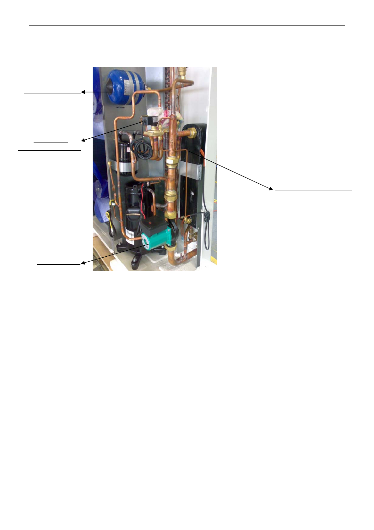
Midea Mini Unitary Chiller is air-cooled chiller and heat pump system, the chiller itself built in with water
pump, expansion tank, plate heat-exchanger; it is very simple for installer to install such kind of system.
Expansion Tank
Pressure
Difference Switch
Plate Heat-exchanger
Water Pump
Introduction 1
Page 4

General Information MCAC-TSM-2008-02
Part 1
General Information
1. Model Names of Outdoor Units....................................3
2. External Appearance ....................................................4
3. Nomenclature................................................................5
4. Features .........................................................................6
2 General Information
Page 5

MCAC-TSM-2008-02 Model Names of Outdoor Units
1. Model Names of Outdoor Units
Model Refrigerant Capacity Power Supply(V-ph-Hz)
MGC-F05W/N1 R410A 5.0kW 220~240-1-50
MGC-F07W/N1 R410A 7.2kW 220~240-1-50
MGC-F09W/N1 R410A 9.0kW 220~240-1-50
MGC-F10W/N1 R410A 10.5kW 220~240-1-50
MGC-F10W/SN1 R410A 10.5kW 380~415-3-50
MGC-F12W/SN1 R410A 12.0kW 380~415-3-50
MGC-F14W/SN1 R410A 14.0kW 380~415-3-50
MGC-F16W/SN1 R410A 16.0kW 380~415-3-50
General Information 3
Page 6
External Appearance MCAC-TSM-2008-02
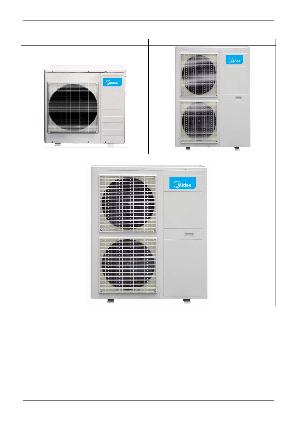
2. External Appearance
MGC-F05W/N1 MGC-F07W/N1 MGC-F09W/N1 MGC-F10W/(S)N1
MGC-F12W/SN1 MGC-F14W/SN1 MGC-F16W/SN1
4 General Information
Page 7
MCAC-TSM-2008-02 Nomenclature
3. Nomenclature
MGC - F 14 W / S N1
Refrigerant
N1 R410A
Power Supply
S: 380-415V, 50Hz, 3ph
--: 220-240V, 50Hz, 1ph
Outdoor Unit
Capacity(14kW)
F: Fixed Speed Type
Midea Mini Unitary Chiller
General Information 5
Page 8
Features MCAC-TSM-2008-02
4. Features
1. Adopts R410A refrigerant, friendly to our environment.
2. Compact design: built-in with water pump and expansion tank, only need to connect the water pipe,
making simple installation.
3. Built-in with emergency switch: switch off the unit manually in any emergency case.
Water pressure gauge: Inspect the water pressure any time
Emergency switch:
Stop the chiller directly by the switch in any urgent case
Controller:
Control interface of the chiller;
Working status inspection and error display.
4. Built-in with water pressure gauge: inspect water pressure all the time.
5. Flexible control: built-in with controller inside the chiller and can be controlled in the room by remote
control keyboard.
6. Built-in with voltage protection, current protection, anti-freezing protection, water flow protection and
so on, guarantees the system work safety.
6 General Information
Page 9

MCAC-TSM-2008-02 Outdoor units
Part 2
Outdoor units
1. Specification..................................................................8
2. Dimensions (unit: mm)...............................................12
3. Service Space (unit: mm)...........................................15
4. Piping Diagram............................................................16
5. Wiring Diagrams..........................................................17
6. Electric Characteristics..............................................20
7. Capacity Tables...........................................................21
8. Operation Limits..........................................................37
9. Sound Level.................................................................39
10. Exploded View...........................................................40
11. Troubleshooting........................................................52
Outdoor units 7
Page 10
Specification MCAC-TSM-2008-02
1. Specification
Model MGC-F05W/N1 MGC-F07W/N1
Power supply V-Ph-Hz
Cooling
Heating
Max. input consumption W 2350 3200
Max. input current A 11.7 16.7
Starting current A 36.8 55
Compressor
Outdoor fan
motor
Outdoor coil
Water pump
Capacity kW 5 7.2
Input W 1938 2755
Capacity kW 5.5 7.7
Input W 1987 2834
Model PA225X2CS-4KU1 PA330X3CS-4MU1
Type ROTARY ROTARY
Brand Midea-Toshiba Midea-Toshiba
Capacity Btu/h 18493 27807.8
Input W 1855 2760
Rated current (RLA) A 8.7 13.1
Locked rotor Amp (LRA) A 36.8 63
Thermal protector
Capacitor uF 50uF/440V-450V 55uF/450V
Refrigerant oil ml ESTER OIL VG74, 750 ESTER OIL VG74, 1100
Model YDK120-8U YDK120-8U
Type
Brand
Input (Hi/Lo) W 220 220
Capacitor uF 6uF/450V 6uF/450V
Speed (Hi/Lo) r/min 660 660
Number of rows 1 1
Tube pitch(a)× row pitch(b) mm
Fin spacing mm 1.6 1.6
Fin type Hydrophilic aluminium foil Hydrophilic aluminium foil
Tube outside dia. and type mm
Coil length ×height × width mm 893×880 893×880
Number of circuits 4 7
Type RS15/6-3-WILO RS15/6-3-WILO
Input (H/M/L) W 93/67/46 93/67/46
220-240, 1, 50 220-240, 1, 50
Inner Inner
AC motor AC motor
Welling Welling
22×19.05 22×19.05
φ7.94 φ7.94
Inner grooved copper tube Inner grooved copper tube
Outdoor air flow m3/h 5563 5624
Throttle Capillary Capillary
Outdoor noise level (sound pressure) dB(A) 55 56
Water flow volume m3/h 0.86 1.24
The plate heat-exchanger water pressure drop kpa 21 35
The Max. and Min. water inlet pressure kpa
Dimension (W×H×D) mm 990×966×354 990×966×354
Outdoor unit
Refrigerant
type/Quantity
Connection
wiring
Pipe diameter Water inlet/outlet mm R1 R1
Control Wired controller Wired controller
Ambient temp. ℃
Nominal capacity is based on the following conditions:
1. Condenser air in 35℃. Evaporator water in/out 12/7℃
2. Evaporator air in 7℃ 85% R.H., Condenser water in/out 40/45℃
3. The two types of oil are equivalents
4. At 1m in open field fan side (sound pressure)
5. The maximum and minimum operating pressure values refer to the activation of the pressure switches
Packing (W×H×D) mm 1120×1100×435 1120×1100×435
Net/ Gross weight kg 83/89 94/100
Type R410A R410A
Charged volume g 1600 2100
Power wiring mm2 3×2.5 3×2.5
Signal wiring (connect to wired
control)
mm
2
500/150 500/150
3×1.0 3×1.0
Cooling: 10℃~43℃; Heating: -15-24℃
8 Installation
Page 11
MCAC-TSM-2008-02 Outdoor units
Si
Model MGC-F09W/N1 MGC-F10W/N1
Power supply V-Ph-Hz
Cooling
Heating
Max. input consumption W 4950
Max. input current A 23.1
Starting current A 98
Compressor
Outdoor fan motor
Outdoor coil
Water pump
Capacity kW 9.0
Input W 3540
Capacity kW 9.5
Input W 3820
Model
Type
Brand
Capacity Btu/h
Input W
Rated current (RLA) A
Locked rotor Amp (LRA) A
Thermal protector
Capacitor uF
Refrigerant oil ml
Model
Type
Brand
Input (Hi/Lo) W
Capacitor uF
Speed (Hi/Lo) r/min
Number of rows
Tube pitch(a)× row pitch(b) mm
Fin spacing mm
Fin type
Tube outside dia. and type mm
Coil length ×height × width mm
Number of circuits
Type
Input (H/M/L) W
220-240, 1, 50 220-240 , 1, 50
10.5
3614
12
4004
5500
25.7
110
ZP50K3E-PFZ-522 ZP50K3E-PFZ-522
SCROLL SCROLL
Copeland Copeland
42600 42600
4100 4100
19.5 19.5
123 123
Inner Inner
80 80
1656 1656
YDK100-6A(×2) YDK100-6A(×2)
AC motor AC motor
Welling Welling
185/120 185/120
5uF/450V 5uF/450V
860/610 860/610
3 3
25.4×22 25.4×22
1.5 1.5
Hydrophilic aluminium foil Hydrophilic aluminium foil
φ9.53 φ9.53
inner groove tube inner groove tube
635×1220×66 635×1220×66
6 6
RL25/8.5 RL25/8.5
210/175/120 210/175/120
Outdoor air flow m3/h 6450/4250
Throttle
Outdoor noise level (sound pressure) dB(A) 58/49 60/50
Water flow volume m3/h 1.54
The plate heat-exchanger water pressure drop kpa 42
The Max. and Min. water inlet pressure kpa
Dimension (W×H×D) mm
Outdoor unit
Refrigerant
type/Quantity
Connection wiring
Pipe diameter Water inlet/outlet mm
Control
Ambient temp. ℃
Nominal capacity is based on the following conditions:
1. Condenser air in 35℃. Evaporator water in/out 12/7℃
2. Evaporator air in 7℃ 85% R.H., Condenser water in/out 40/45℃
3. The two types of oil are equivalents
4. At 1m in open field fan side (sound pressure)
5. The maximum and minimum operating pressure values refer to the activation of the pressure switches
Packing (W×H×D) mm 1058×1380×438
Net/ Gross weight kg
Type R410A
Charged volume g
Power wiring mm2 3×4.0
gnal wiring (connect to wired
mm2
Capillary Capillary
500/150 500/150
940×1245×360 940×1245×360
138/145 138/145
3000 3000
3×1.0 3 ×1.0
R5/4 R5/4
Wired controller Wired controller
Cooling: 10℃~43℃; Heating: -15-24℃
6500/4300
1.74
44
1058×1380×438
R410A
3×4.0
Outdoor units 9
Page 12
Specification MCAC-TSM-2008-02
Model MGC-F10W/SN1 MGC-F12W/SN1
Power supply V-Ph-Hz
Cooling
Heating
Max. input consumption W
Max. input current A
Starting current A
Compressor
Outdoor fan
motor
Outdoor coil
Water pump
Capacity kW
Input W
Capacity kW
Input W
Model
Type
Brand
Capacity Btu/h
Input W
Rated current (RLA) A
Locked rotor Amp (LRA) A
Thermal protector
Capacitor uF
Refrigerant oil ml
Model
Type
Brand
Input (Hi/Lo) W
Capacitor uF
Speed (Hi/Lo) r/min
Number of rows
Tube pitch(a)× row pitch(b) mm
Fin spacing mm
Fin type
Tube outside dia. and type mm
Coil length ×height × width mm
Number of circuits
Type
Input (H/M/L) W
380-415 , 3, 50 380-415 , 3, 50
10.5 12
3930 4410
12 14
4240 4643
4400 5000
8.3 9.1
45 66
ZP50K3E-TFD-522 C-SBN373H8D
SCROLL SCROLL
Copeland SANYO
42300 48109.2
4100 4750
7.3 8.22
64 66
Inner Inner
/ /
POE OIL,1952 FV68S, 1700
YDK100-6A(×2) YDK100-6A(×2)
AC motor AC motor
Welling Welling
185/120 185/120
5uF/450V 5uF/450V
860/610 860/610
2 2
22×19.05 22×19.05
1.5 1.5
Hydrophilic aluminium foil Hydrophilic aluminium foil
φ7.94 φ7.94
Inner grooved copper tube Inner grooved copper tube
807×1188×38.1 945×1188×38.1
7 7
RL25/8.5 RL25/8.5
210/175/120 210/175/120
Outdoor air flow m3/h
Throttle
Outdoor noise level (sound pressure) dB(A)
Water flow volume m3/h
The plate heat-exchanger water pressure drop kpa
The Max. and Min. water inlet pressure kpa
Dimension (W×H×D) mm
Outdoor unit
Refrigerant
type/Quantity
Connection
wiring
Pipe diameter Water inlet/outlet mm
Control
Ambient temp. ℃
Nominal capacity is based on the following conditions:
1. Condenser air in 35℃. Evaporator water in/out 12/7℃
2. Evaporator air in 7℃ 85% R.H., Condenser water in/out 40/45℃
3. The two types of oil are equivalents
4. At 1m in open field fan side (sound pressure)
5. The maximum and minimum operating pressure values refer to the activation of the pressure switches
Packing (W×H×D) mm 1058×1380×438 1188×1385×498
Net/ Gross weight kg 131/139 137/145
Type R410A R410A
Charged volume g 2700
Power wiring mm2
Signal wiring (connect to wired
control)
mm2
6465/4270 6470/4280
Capillary Capillary
58/48 59/49
1.72 2.0
44 40
500/150 500/150
940×1245×360 1070×1249×420
5×2.5 5×2.5
3×1.0 3×1.0
R5/4 R5/4
Wired controller Wired controller
Cooling: 10℃~43℃; Heating: -15-24℃
3000
10 Installation
Page 13
MCAC-TSM-2008-02 Outdoor units
Model MGC-F14W/SN1 MGC-F16W/SN1
Power supply V-Ph-Hz
Cooling
Heating
Max. input consumption W
Max. input current A
Starting current A
Compressor
Outdoor fan motor
Outdoor coil
Water pump
Capacity kW
Input W
Capacity kW
Input W
Model
Type
Brand
Capacity Btu/h
Input W
Rated current (RLA) A
Locked rotor Amp (LRA) A
Thermal protector
Capacitor uF
Refrigerant oil ml
Model
Type
Brand
Input (Hi/Lo) W
Capacitor uF
Speed (Hi/Lo) r/min
Number of rows
Tube pitch(a)× row pitch(b) mm
Fin spacing mm
Fin type
Tube outside dia. and type mm
Coil length ×height × width mm
Number of circuits
Type
Input (H/M/L) W
380-415 , 3, 50 380-415 , 3, 50
14 16
4859 6430
16.12 18
5218 6444
6550 7700
10.5 14.3
60 92
C-SBN453H8D C-SBN523H8D
SCROLL SCROLL
SANYO SANYO
56000 65510
5750 6750
9.77 11.6
67 73
Inner Inner
/ /
FV68S, 1600 FV68S, 1700
YDK100-6A(×2) YDK100-6A(×2)
AC motor AC motor
Welling Welling
185/120 185/120
5uF/450V 5uF/450V
860/610 860/610
3 3
25.4×22 22×19.05
1.5 1.6
Hydrophilic aluminium foil Hydrophilic aluminium foil
φ9.53 φ7.94
Inner grooved copper tube Inner grooved copper tube
718 ×1220×66 937×1188×57.15
12 14
RL25/8.5 RL25/8.5
210/175/120 210/175/120
Outdoor air flow m3/h
Throttle
Outdoor noise level (sound pressure) dB(A) 60/50
Water flow volume m3/h
The plate heat-exchanger water pressure drop kpa
The Max. and Min. water inlet pressure kpa
Dimension (W×H×D) mm
Outdoor unit
Refrigerant
type/Quantity
Connection wiring
Pipe diameter Water inlet/outlet mm
Control
Ambient temp. ℃
Nominal capacity is based on the following conditions:
1. Condenser air in 35℃. Evaporator water in/out 12/7℃
2. Evaporator air in 7℃ 85% R.H., Condenser water in/out 40/45℃
3. The two types of oil are equivalents
4. At 1m in open field fan side (sound pressure)
5. The maximum and minimum operating pressure values refer to the activation of the pressure switches
Packing (W×H×D) mm
Net/ Gross weight kg 145/160
Type
Charged volume g
Power wiring mm2
Signal wiring (connect to wired
control)
mm
2
6500/4300 6550/4483
Capillary Capillary
2.4 2.8
34 38
500/150 500/150
1070×1249×420 1070×1249×420
1188×1385×498 1188×1385×498
R410A
3600 4200
5×2.5 5×4.0
3×1.0 3×1.0
R5/4 R5/4
Wired controller Wired controller
Cooling: 10℃~43℃; Heating: -15-24℃
60/51
142/150
R410A
Outdoor units 11
Page 14
Specification MCAC-TSM-2008-02
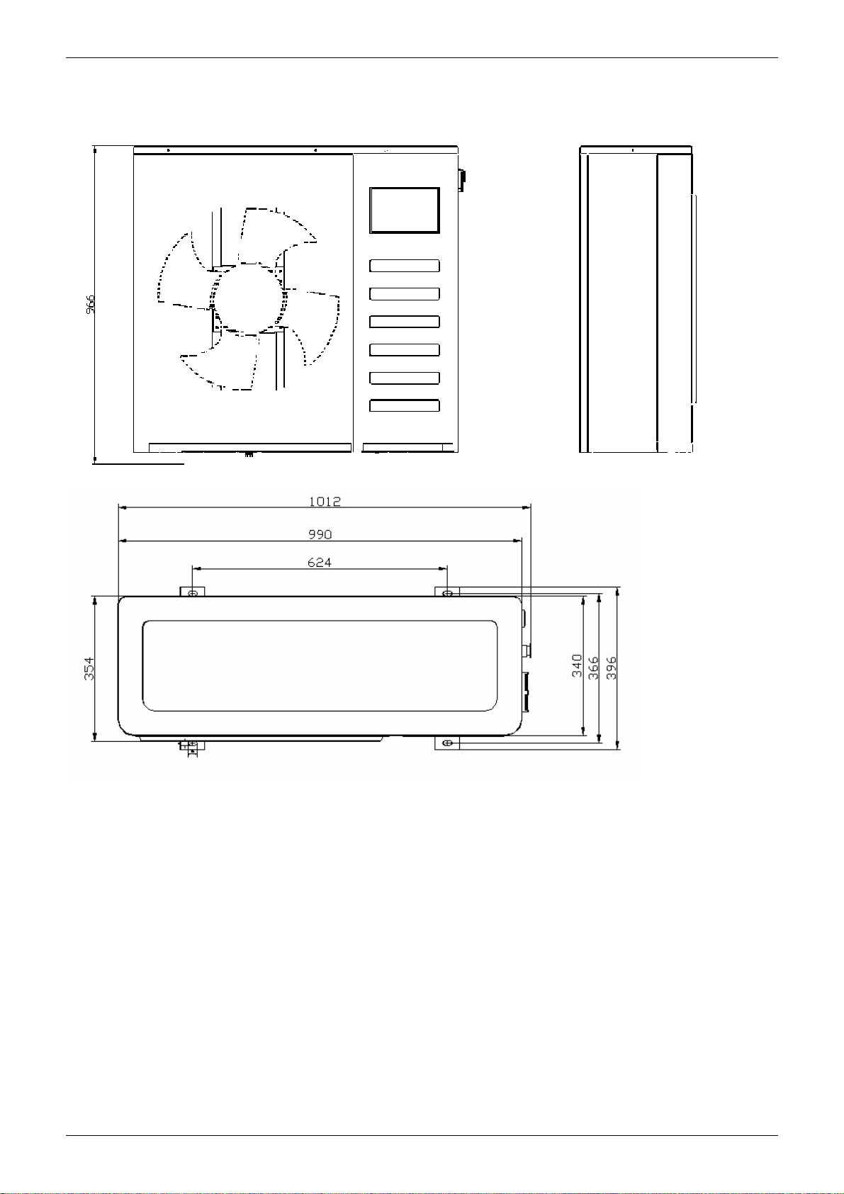
2. Dimensions (unit: mm)
2.1 MGC-F05W/N1 MGC-F07W/N1
12 Installation
Page 15
MCAC-TSM-2008-02 Outdoor units
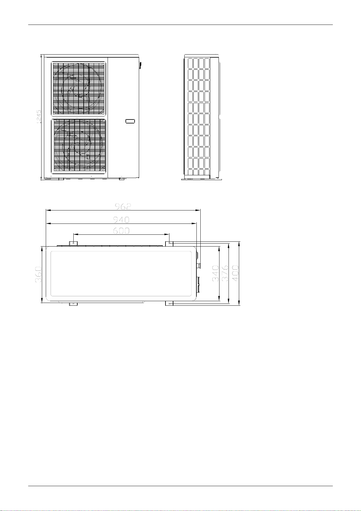
2.2 MGC-F09W/N1 MGC-F10W/N1 MGC-F10W/SN1
Outdoor units 13
Page 16
Specification MCAC-TSM-2008-02
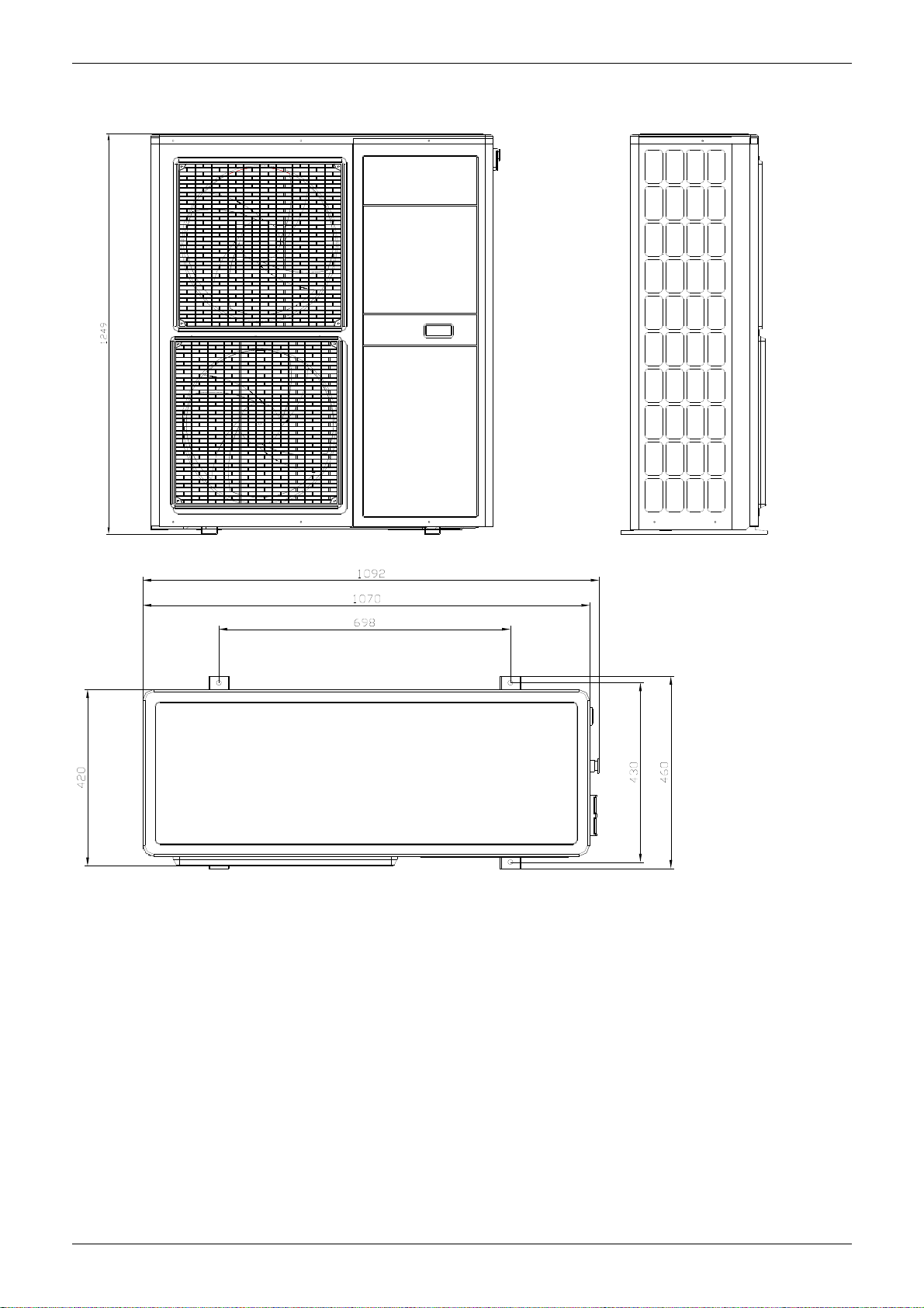
2.3 MGC-F12W/SN1 MGC-F14W/SN1 MGC-F16W/SN1
14 Installation
Page 17
MCAC-TSM-2008-02 Outdoor units
3. Service Space (unit: mm)
Dimension A B C D E
MGC-F05W/N1 990 966 354 624 366
MGC-F07W/N1 990 966 354 624 366
MGC-F09W/N1 940 1245 360 600 376
MGC-F10W/N1 940 1245 360 600 376
MGC-F10W/SN1 940 1245 360 600 376
MGC-F12W/SN1 1070 1249 420 698 430
MGC-F14W/SN1 1070 1249 420 698 430
MGC-F16W/SN1 1070 1249 420 698 430
Outdoor units 15
Page 18
Specification MCAC-TSM-2008-02
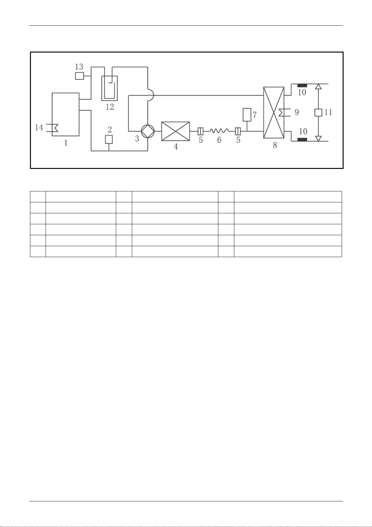
4. Piping Diagram
Remark:
No Name No Name No Name
1 Compressor 6 Capillary 11 Water differential pressure switch
2 High pressure switch 7 Liquid receiver 12 Accumulator
3 4-way valve 8 Plate heat exchanger 13 Low pressure switch
4 Condenser 9 Defrost heater 14 Crankcase heater
5 Filter 10 Water temperature sensor
16 Installation
Page 19
MCAC-TSM-2008-02 Outdoor units
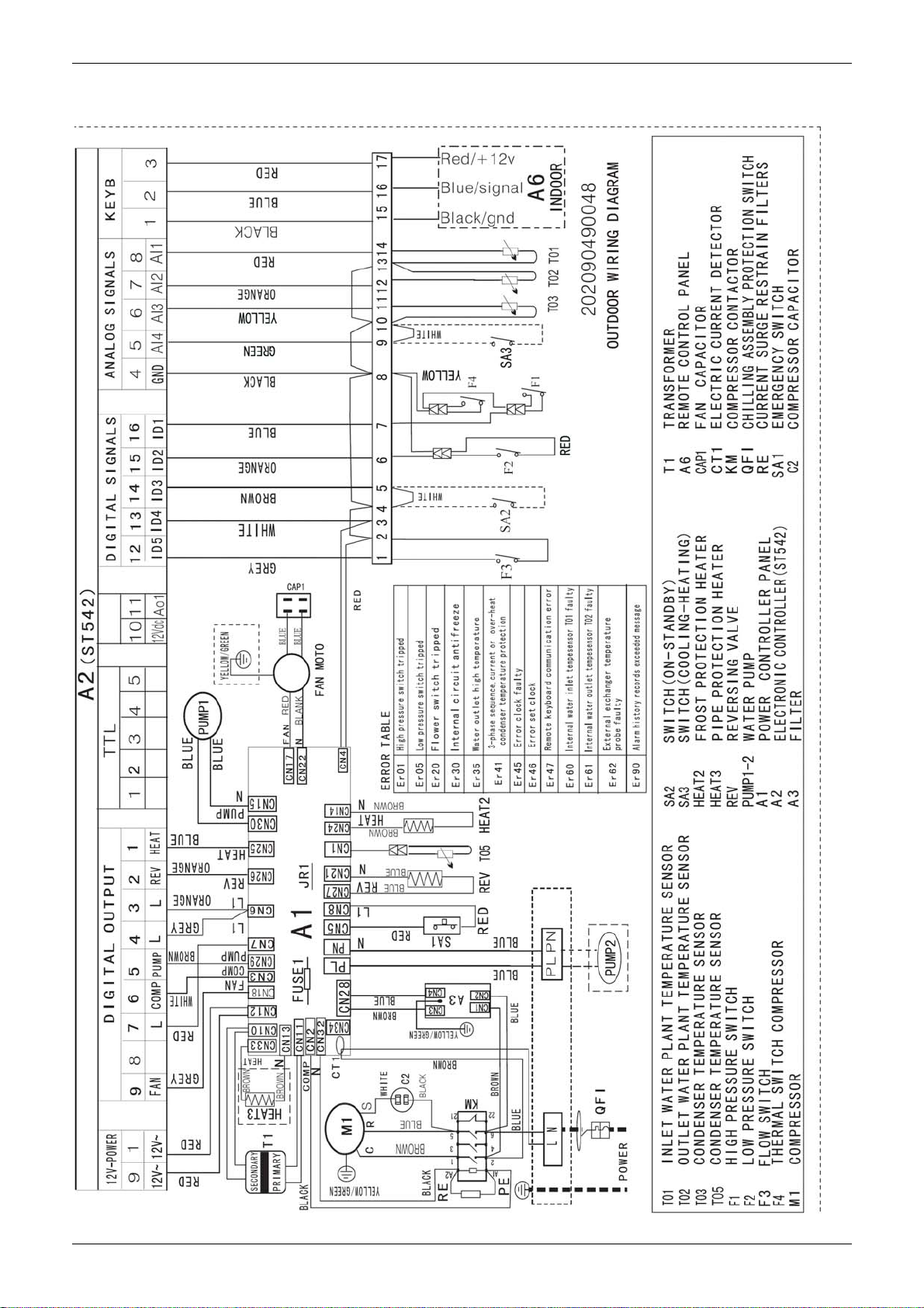
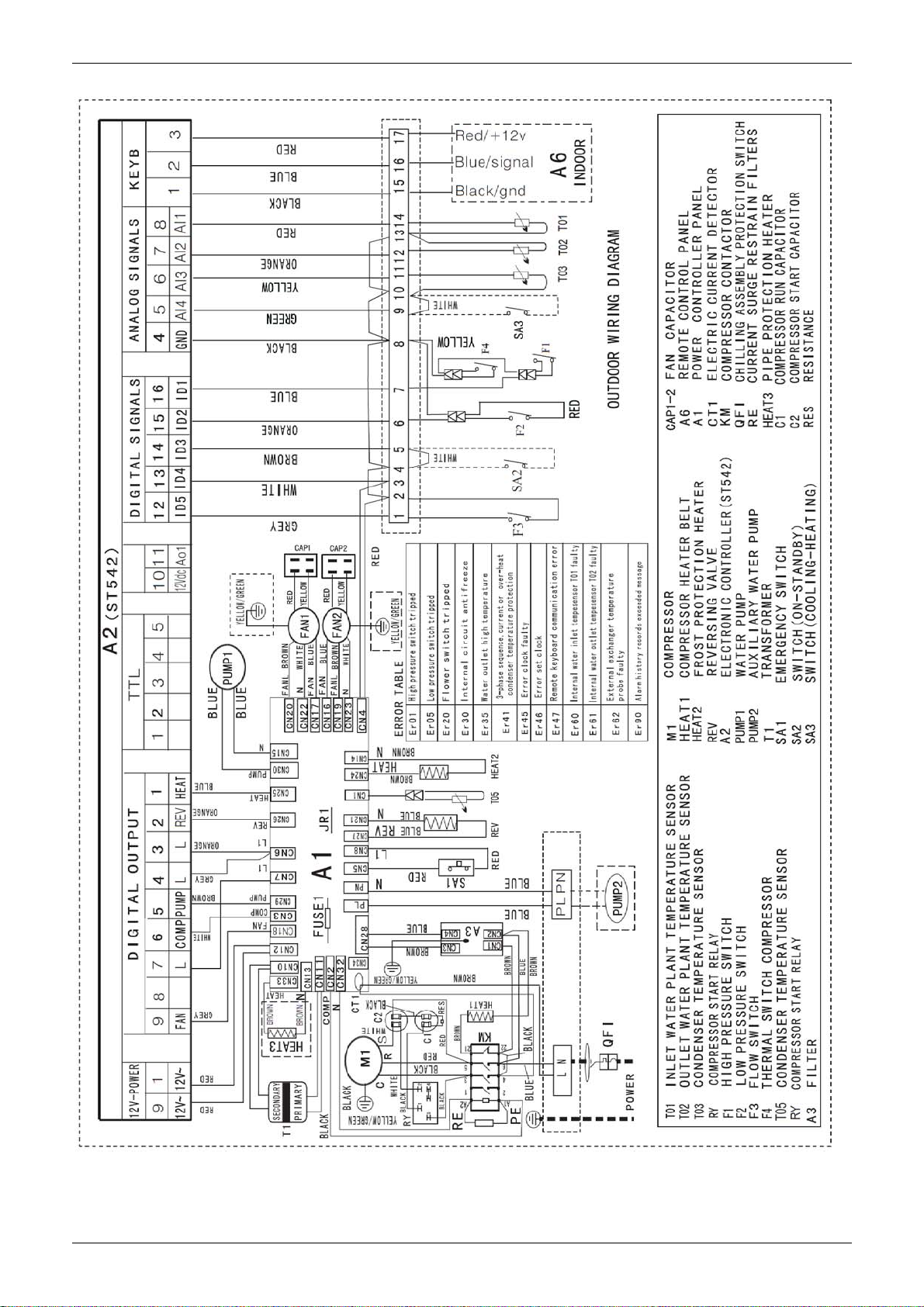
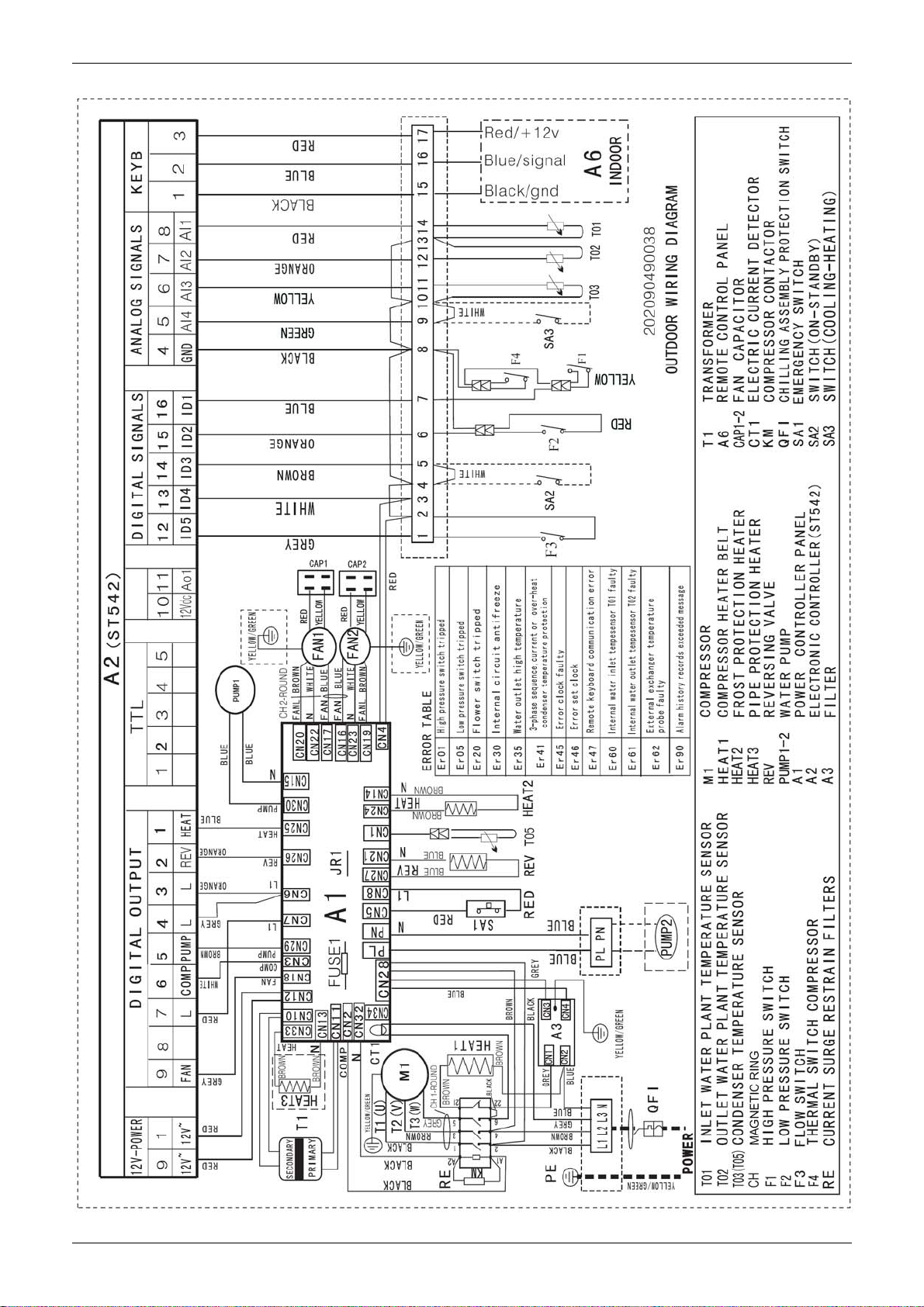
5. Wiring Diagrams
5.1 MGC-F05W/N1 MGC-F07W/N1
Outdoor units 17
Page 20
Specification MCAC-TSM-2008-02
5.2 MGC-F09W/N1 MGC-F10W/N1
18 Installation
Page 21
MCAC-TSM-2008-02 Outdoor units
5.3 MGC-F10W/SN1 MGC-F12W/SN1 MGC-F14W/SN1 MGC-F16W/SN1
Outdoor units 19
Page 22
Specification MCAC-TSM-2008-02
6. Electric Characteristics
Model
Hz Voltage phase Min. Max. MCA TOCA MFA MSC RLA kW FLA
MGC-F05W/N1 50Hz 220-240V 1ph 198V 254V 11.25 10.8 15 36.8 8.7 0.12 1
MGC-F07W/N1 50Hz 220-240V 1ph 198V 254V 17.5 16.6 20 63 13.1 0.12 1
MGC-F09W/N1 50Hz 220-240V 1ph 198V 254V 24.5 32 35 123 19.5 0.1×2 0.8×2
MGC-F10W/N1 50Hz 220-240V 1ph 198V 254V 24.5 32 35 123 19.5 0.1×2 0.8×2
MGC-F10W/SN1 50Hz 380-415V 3ph 342V 440V 9.2 10.5 20 64 7.3 0.1×2 0.8×2
MGC-F12W/SN1 50Hz 380-415V 3ph 342V 440V 12.12 11.5 15 66 8.22 0.1×2 0.8×2
MGC-F14W/SN1 50Hz 380-415V 3ph 342V 440V 10.2 25 15 67 9.77 0.1×2 0.8×2
MGC-F16W/SN1 50Hz 380-415V 3ph 342V 440V 15.75 15 20 73 11.6 0.1×2 0.8×2
Remark:
MCA: Min. Current Amps. (A)
TOCA: Total Over-current Amps. (A)
MFA: Max. Fuse Amps. (A)
MSC: Max. Starting Amps. (A)
RLA: Rated Current Amps. (A)
OFM: Outdoor Fan Motor
FLA: Full Load Amps. (A)
kW: Rated Motor Output. (kW)
Outdoor Unit Power Supply Compressor OFM
20 Installation
Page 23
MCAC-TSM-2008-02 Outdoor units
7. Capacity Tables
Cooling
MGC-F05W/N1
Ta
25.0
30.0
35.0
40.0
43.0
Note:
Ta: outside air temperature (°C)
Tw : evaporator water outlet temperature (°C)
Pf: cooling capacity (kW)
Pa: compressor power input (kW)
Pat: total power input (kW)
Qev: evaporator water flow (m
ΔPev: evaporator pressure drop (kPa)
Tw 5.0 6.0 7.0 8.0 9.0 10.0
Pf 5.1 5.2 5.4 5.5 5.6 5.8
Pa 1.5 1.5 1.5 1.5 1.6 1.6
Pat 1.8 1.8 1.8 1.8 1.9 1.9
Qev 0.88 0.89 0.93 0.95 0.96 1.00
ΔPev 21.6 23.0 24.6 26.3 27.8 29.5
Pf 4.9 5.0 5.1 5.3 5.4 5.5
Pa 1.8 1.8 1.8 1.8 1.9 1.9
Pat 2.1 2.1 2.1 2.1 2.2 2.2
Qev 0.84 0.86 0.88 0.91 0.93 0.95
ΔPev 18.4 19.7 22.1 23.6 25.1 26.6
Pf 4.8 4.9 5.0 5.1 5.2 5.3
Pa 1.8 1.8 1.8 1.9 1.9 1.9
Pat 2.1 2.1 2.1 2.2 2.2 2.2
Qev 0.83 0.84 0.86 0.88 0.89 0.91
ΔPev 18.5 19.8 21.0 22.5 24.0 25.5
Pf 4.6 4.7 4.9 5.0 5.1 5.2
Pa 1.9 1.9 1.9 2.0 2.0 2.0
Pat 2.2 2.2 2.2 2.3 2.3 2.3
Qev 0.79 0.81 0.84 0.86 0.88 0.89
ΔPev 17.1 18.3 19.6 20.9 22.3 23.7
Pf 4.3 4.5 4.6 4.7 4.9 5.0
Pa 2.1 2.1 2.1 2.2 2.2 2.2
Pat 2.4 2.4 2.4 2.5 2.5 2.5
Qev 0.74 0.77 0.79 0.81 0.84 0.86
ΔPev 14.8 15.9 17.1 18.3 19.5 20.8
3
/h)
Outdoor units 21
Page 24
Specification MCAC-TSM-2008-02
MGC-F07W/N1
Ta
25.0
30.0
35.0
40.0
43.0
Note:
Ta: outside air temperature (°C)
Tw : evaporator water outlet temperature (°C)
Pf: cooling capacity (kW)
Pa: compressor power input (kW)
Pat: total power input (kW)
Qev: evaporator water flow (m 3 /h)
ΔPev: evaporator pressure drop (kPa)
Tw 5.0 6.0 7.0 8.0 9.0 10.0
Pf 7.3 7.4 7.6 7.7 7.8 8.0
Pa 2.3 2.3 2.3 2.3 2.4 2.4
Pat 2.6 2.6 2.6 2.6 2.7 2.7
Qev 1.26 1.27 1.31 1.32 1.34 1.38
ΔPev 35.6 37.0 38.6 40.3 41.8 43.5
Pf 7.1 7.2 7.3 7.5 7.6 7.7
Pa 2.6 2.6 2.6 2.6 2.7 2.7
Pat 2.9 2.9 2.9 2.9 3.0 3.0
Qev 1.22 1.24 1.26 1.29 1.31 1.32
ΔPev 32.4 33.7 36.1 37.6 39.1 40.6
Pf 7.0 7.1 7.2 7.3 7.4 7.5
Pa 2.6 2.6 2.6 2.7 2.7 2.7
Pat 2.9 2.9 2.9 3.0 3.0 3.0
Qev 1.20 1.22 1.24 1.26 1.27 1.29
ΔPev 32.5 33.8 35.0 36.5 38.0 39.5
Pf 6.8 6.9 7.1 7.2 7.3 7.4
Pa 2.7 2.7 2.7 2.8 2.8 2.8
Pat 3.0 3.0 3.0 3.1 3.1 3.1
Qev 1.17 1.19 1.22 1.24 1.26 1.27
ΔPev 31.1 32.3 33.6 34.9 36.3 37.7
Pf 6.5 6.7 6.8 6.9 7.1 7.2
Pa 2.9 2.9 2.9 3.0 3.0 3.0
Pat 3.2 3.2 3.2 3.3 3.3 3.3
Qev 1.12 1.15 1.17 1.19 1.22 1.24
ΔPev 28.8 29.9 31.1 32.3 33.5 34.8
22 Installation
Page 25
MCAC-TSM-2008-02 Outdoor units
MGC-F09W/N1
Ta Tw 5 6 7 8 9 10
Pf 8.3 8.6 8.9 9.2 9.5 9.8
Pa 2.6 2.6 2.6 2.7 2.7 2.7
25
30
35
40
Pat 2.9 2.9 2.9 3.0 3.0 3.0
Qev 1.4 1.5 1.5 1.6 1.6 1.7
Pev△ 36 41 43 46.4 48 51
Pf 7.9 8.2 8.5 8.8 9.1 9.4
Pa 2.8 2.8 2.8 2.9 2.9 2.9
Pat 3.1 3.1 3.1 3.2 3.2 3.2
Qev 1.3 1.4 1.4 1.5 1.5 1.6
Pev△ 29.5 32.1 35.6 39.0 41.8 47.0
Pf 7.5 7.8 8.0 8.2 8.5 8.8
Pa 3.1 3.1 3.2 3.3 3.3 3.3
Pat 3.4 3.4 3.5 3.6 3.6 3.6
Qev 1.3 1.3 1.4 1.4 1.5 1.5
Pev△ 28.0 30.4 33.9 35.0 38.0 420
Pf 7.0 7.3 7.5 7.7 8.0 8.3
Pa 3.4 3.4 3.5 3.6 3.6 3.6
Pat 3.7 3.7 3.8 3.9 3.9 3.9
Qev 1.2 1.3 1.3 1.4 1.4 1.4
Pev△ 24.0 26.0 26.8 28.0 32.1 35.3
Pf 6.8 7.1 7.3 7.5 7.8 8.1
Pa 3.6 3.6 3.7 3.8 3.8 3.8
43
Note:
Ta: outside air temperature (°C)
Tw : evaporator water outlet temperature (°C)
Pf: cooling capacity (kW)
Pa: compressor power input (kW)
Pat: total power input (kW)
Qev: evaporator water flow (m
ΔPev: evaporator pressure drop (kPa)
Pat 3.9 3.9 4.0 4.1 4.1 4.1
Qev 1.1 1.2 1.2 1.3 1.3 1.4
Pev△ 20.0 23.5 24.6 28.0 31.0 34.0
3
/h)
Outdoor units 23
Page 26

Specification MCAC-TSM-2008-02
MGC-F10W/N1
Ta Tw 5 6 7 8 9 10
Pf 10.9 11.2 11.5 11.8 12.1 12.4
Pa 2.6 2.6 2.7 2.7 2.7 2.8
25
30
35
40
Pat 3.1 3.1 3.2 3.2 3.2 3.3
Qev 1.9 1.9 2.0 2.0 2.1 2.2
Pev△ 31.5 31.7 33.0 33.5 36.0 38.0
Pf 10.4 10.8 11.1 11.5 11.8 12.1
Pa 2.9 2.9 3.0 3.1 3.1 3.1
Pat 3.4 3.4 3.5 3.6 3.6 3.6
Qev 1.8 1.8 1.9 2.0 2.0 2.0
Pev△ 29.8 30.4 31.8 33.2 33.6 33.9
Pf 9.9 10.2 10.5 10.7 11.0 11.3
Pa 3.3 3.3 3.4 3.4 3.5 3.5
Pat 3.8 3.8 3.9 3.9 4.0 4.0
Qev 1.7 1.7 1.8 1.9 1.9 2.0
Pev△ 27.0 27.5 30.0 32.0 32.4 34.0
Pf 9.4 9.7 10.0 10.3 10.6 11.0
Pa 3.6 3.6 3.7 3.7 3.8 3.8
Pat 4.1 4.1 4.2 4.2 4.3 4.3
Qev 1.6 1.6 1.7 1.7 1.8 1.8
Pev△ 24.0 24.4 27.2 27.6 30.3 30.5
Pf 9.0 9.3 9.5 9.8 10.0 10.3
Pa 3.8 3.8 3.9 3.9 4.0 4.0
43
Note:
Ta: outside air temperature (°C)
Tw : evaporator water outlet temperature (°C)
Pf: cooling capacity (kW)
Pa: compressor power input (kW)
Pat: total power input (kW)
Qev: evaporator water flow (m
ΔPev: evaporator pressure drop (kPa)
Pat 4.3 4.3 4.4 4.4 4.5 4.5
Qev 1.5 1.6 1.6 1.7 1.7 1.8
Pev△ 21.0 23.8 24.4 27.0 27.5 31.0
3
/h)
24 Installation
Page 27
MCAC-TSM-2008-02 Outdoor units
MGC-F10W/SN1
Ta Tw 5 6 7 8 9 10
Pf 10.9 11.2 11.5 11.8 12.1 12.4
Pa 2.6 2.6 2.7 2.7 2.7 2.8
25
30
35
40
Pat 3.1 3.1 3.2 3.2 3.2 3.3
Qev 1.9 1.9 2.0 2.0 2.1 2.2
△Pev
Pf 10.4 10.8 11.1 11.5 11.8 12.1
Pa 2.9 2.9 3.0 3.1 3.1 3.1
Pat 3.4 3.4 3.5 3.6 3.6 3.6
Qev 1.8 1.8 1.9 2.0 2.0 2.0
△Pev
Pf 9.9 10.2 10.5 10.7 11.0 11.3
Pa 3.3 3.3 3.4 3.4 3.5 3.5
Pat 3.8 3.8 3.9 3.9 4.0 4.0
Qev 1.7 1.7 1.8 1.9 1.9 2.0
△Pev
Pf 9.4 9.7 10.0 10.3 10.6 11.0
Pa 3.6 3.6 3.7 3.7 3.8 3.8
Pat 4.1 4.1 4.2 4.2 4.3 4.3
Qev 1.6 1.6 1.7 1.7 1.8 1.8
31.5 31.7 33.0 33.5 36.0 38.0
29.8 30.4 31.8 33.2 33.6 33.9
27.0 27.5 30.0 32.0 32.4 34.0
△Pev
Pf 9.0 9.3 9.5 9.8 10.0 10.3
Pa 3.8 3.8 3.9 3.9 4.0 4.0
43
Note:
Ta: outside air temperature (°C)
Tw : evaporator water outlet temperature (°C)
Pf: cooling capacity (kW)
Pa: compressor power input (kW)
Pat: total power input (kW)
Qev: evaporator water flow (m
ΔPev: evaporator pressure drop (kPa)
Pat 4.3 4.3 4.4 4.4 4.5 4.5
Qev 1.5 1.6 1.6 1.7 1.7 1.8
△Pev
24.0 24.4 27.2 27.6 30.3 30.5
21.0 23.8 24.4 27.0 27.5 31.0
3
/h)
Outdoor units 25
Page 28
Specification MCAC-TSM-2008-02
MGC-F12W/SN1
Ta Tw 5 6 7 8 9 10
Pf 12.4 12.7 13.0 13.3 13.9
Pa 3.5 3.5 3.5 3.6 3.6 3.6
25
30
35
40
Pat 4.1 4.1 4.1 4.2 4.2 4.2
Qev 2.2 2.2 2.3 2.3 2.3 2.4
Pev△ 29.1 29.9 31.0 32.4 34.1 37.5
Pf 11.9 12.2 12.5 12.8 13.1 13.4
Pa 3.8 3.8 3.8 3.9 3.9 3.9
Pat 4.4 4.4 4.4 4.5 4.5 4.5
Qev 2.0 2.1 2.1 2.2 2.2 2.3
Pev△ 23.1 23.2 25.4 27.0 28.8 30.0
Pf 11.4 11.7 12.0 12.3 12.6 12.9
Pa 4.2 4.2 4.2 4.3 4.3 4.3
Pat 4.8 4.8 4.8 4.9 4.9 4.9
Qev 2.0 2.0 2.1 2.1 2.2 2.2
Pev△ 21.1 23.2 25.4 27.0 28.8 30.0
Pf 10.9 11.2 11.5 11.8 12.1 12.4
Pa 4.5 4.5 4.5 4.6 4.6 4.6
Pat 5.1 5.1 5.1 5.2 5.2 5.2
Qev 1.9 2.0 2.0 2.0 2.1 2.1
Pev△ 20.2 21.9 22.7 24.0 25.6 28.2
Pf 10.5 10.8 11.1 11.4 11.7 12.0
Pa 4.7 4.7 4.7 4.8 4.8 4.8
43
Note:
Ta: outside air temperature (°C)
Tw : evaporator water outlet temperature (°C)
Pf: cooling capacity (kW)
Pa: compressor power input (kW)
Pat: total power input (kW)
Qev: evaporator water flow (m 3 /h)
ΔPev: evaporator pressure drop (kPa)
Pat 5.3 5.3 5.3 5.4 5.4 5.4
Qev 1.8 1.9 1.9 2.0 2.0 2.0
Pev△ 17.5 18.8 21.1 23.4 24.1 25.3
26 Installation
Page 29
MCAC-TSM-2008-02 Outdoor units
MGC-F14W/SN1
Ta Tw 5 6 7 8 9 10
Pf 14.8 15.1 15.4 15.7 16.1 16.4
Pa 3.6 3.6 3.6 3.7 3.7 3.7
25
30
35
40
Pat 4.1 4.1 4.1 4.2 4.2 4.2
Qev 2.6 2.6 2.7 2.7 2.8 2.8
Pev△ 29.0 29.4 30.4 31.2 33.0 34.0
Pf 14.1 14.4 14.7 15.0 15.3 15.6
Pa 4.1 4.1 4.1 4.2 4.2 4.2
Pat 4.6 4.6 4.7 4.7 4.7 4.7
Qev 2.4 2.5 2.5 2.6 2.6 2.7
Pev△ 25.8 28.2 28.4 28.9 29.5 31.0
Pf 13.4 13.7 14.0 14.3 14.6 14.9
Pa 4.6 4.6 4.6 4.7 4.7 4.7
Pat 5.1 5.1 5.1 5.2 5.2 5.2
Qev 2.3 2.4 2.4 2.5 2.5 2.5
Pev△ 24.0 25.6 26.0 27.6 28.1 28.4
Pf 12.5 12.8 13.1 13.4 13.7 14.0
Pa 5.1 5.1 5.1 5.2 5.2 5.2
Pat 5.6 5.6 5.6 5.7 5.7 5.7
Qev 2.2 2.2 2.3 2.3 2.4 2.4
Pev△ 19.6 20.3 21.6 23.4 25.7 26.4
Pf 12.0 12.3 12.6 12.9 13.2 13.5
Pa 5.5 5.5 5.5 5.6 5.6 5.6
43
Note:
Ta: outside air temperature (°C)
Tw : evaporator water outlet temperature (°C)
Pf: cooling capacity (kW)
Pa: compressor power input (kW)
Pat: total power input (kW)
Qev: evaporator water flow (m 3 /h)
ΔPev: evaporator pressure drop (kPa)
Pat 6.0 6.0 6.0 6.1 6.1 6.1
Qev 2.1 2.1 2.2 2.2 2.3 2.3
Pev△ 18.0 19.1 20.7 21.3 23.0 23.8
Outdoor units 27
Page 30

Specification MCAC-TSM-2008-02
MGC-F16W/SN1
Ta Tw 5 6 7 8 9 10
Pf 15.5 15.7 16.0 16.3 16.5 16.8
Pa 5.0 5.0 5.0 5.1 5.1 5.1
25
30
35
40
Pat 5.5 5.5 5.5 5.6 5.6 5.6
Qev 2.7 2.7 2.8 2.8 2.9 2.9
Pev△ 30.5 32.0 33.0 34.5 36.2 37.6
Pf 14.8 15.0 15.3 15.6 15.8 16.1
Pa 4.5 4.5 4.5 4.6 4.6 4.6
Pat 5.0 5.0 5.0 5.1 5.1 5.1
Qev 2.6 2.6 2.7 2.7 2.8 2.8
Pev△ 28.3 29.4 28.3 30.4 33.3 35.0
Pf 14.9 15.2 15.5 15.8 16.1 16.4
Pa 6.0 6.0 6.0 6.1 6.1 6.1
Pat 6.5 6.5 6.5 6.6 6.6 6.6
Qev 2.6 2.6 2.7 2.7 2.8 2.8
Pev△ 28.2 29.5 31.0 32.3 34.0 35.1
Pf 14.2 14.5 14.8 15.1 15.4 15.7
Pa 5.5 5.5 5.5 5.6 5.6 5.6
Pat 6.0 6.0 6.0 6.1 6.1 6.1
Qev 2.5 2.5 2.6 2.6 2.7 2.7
Pev△ 26.0 27.3 28.6 29.5 31.0 33.0
Pf 13.5 13.8 14.1 14.4 14.7 15.0
Pa 5.0 5.0 5.0 5.1 5.1 5.1
43
Note:
Ta: outside air temperature (°C)
Tw : evaporator water outlet temperature (°C)
Pf: cooling capacity (kW)
Pa: compressor power input (kW)
Pat: total power input (kW)
Qev: evaporator water flow (m 3 /h)
ΔPev: evaporator pressure drop (kPa)
Pat 5.5 5.5 5.5 5.6 5.6 5.6
Qev 2.4 2.4 2.5 2.5 2.6 2.6
Pev△ 23.0 24.6 26.1 27.3 28.6 30.0
28 Installation
Page 31

MCAC-TSM-2008-02 Outdoor units
Heating
MGC-F05W/N1
Ta
U.R.87%
Tw 35 40 45 50
Pt 4.2 4.2 4.1 -
Pa 1.3 1.5 1.6 -
-5
0
7
10
Pat 1.5 1.7 1.8 -
Qc 0.72 0.72 0.71 -
ΔPc 14.6 14.5 14.1 -
Pt 4.8 4.8 4.7 4.7
Pa 1.3 1.5 1.7 1.9
Pat 1.6 1.8 2 2.2
Qc 0.83 0.83 0.81 0.81
ΔPc 18.5 18.4 18.1 18.1
Pt 5.6 5.5 5.5 5.4
Pa 1.4 1.5 1.7 1.9
Pat 1.7 1.8 2 2.2
Qc 0.96 0.95 0.95 0.93
ΔPc 23.9 23.4 23 22.9
Pt 6.1 6.1 6 6
Pa 1.4 1.5 1.7 1.9
Pat 1.7 1.8 2 2.2
Qc 1.05 1.05 1.03 1.03
ΔPc 27.8 27.5 27.1 27
Pt 6.5 6.5 6.5 6.4
Pa 1.4 1.6 1.7 1.9
15
Note:
Ta: outside air temperature (°C)
Tw : evaporator water outlet temperature (°C)
Pt: heating capacity (kW)
Pa: compressor power input (kW)
Pat: total power input (kW)
Qc: condenser water flow (m3/h)
ΔPc: evaporator pressure drop (kPa)
- : Exceed operating limits
Pat 1.7 1.9 2 2.2
Qc 1.12 1.12 1.12 1.10
ΔPc 33.2 33 32.9 32.5
Outdoor units 29
Page 32

Specification MCAC-TSM-2008-02
MGC-F07W/N1
Ta
U.R.87%
Tw 35 40 45 50
Pt 6.4 6.4 6.3 /
Pa 2.2 2.4 2.5 /
-5
0
7
10
Pat 2.5 2.7 2.8 /
Qc 1.10 1.10 1.08 /
ΔPc 27.6 27.5 27.1 /
Pt 7 7 6.9 6.9
Pa 2.2 2.4 2.6 2.8
Pat 2.5 2.7 2.9 3.1
Qc 1.20 1.20 1.19 1.19
ΔPc 31.5 31.4 31.1 31.1
Pt 7.8 7.7 7.7 7.6
Pa 2.3 2.4 2.6 2.8
Pat 2.6 2.7 2.9 3.1
Qc 1.34 1.32 1.32 1.31
ΔPc 36.9 36.4 36 35.9
Pt 8.3 8.3 8.2 8.2
Pa 2.3 2.4 2.6 2.8
Pat 2.6 2.7 2.9 3.1
Qc 1.43 1.43 1.41 1.41
ΔPc 40.8 40.5 40.1 40
Pt 8.7 8.7 8.7 8.6
Pa 2.3 2.5 2.6 2.8
15
Note:
Ta: outside air temperature (°C)
Tw : evaporator water outlet temperature (°C)
Pt: heating capacity (kW)
Pa: compressor power input (kW)
Pat: total power input (kW)
Qc: condenser water flow (m3/h)
ΔPc: evaporator pressure drop (kPa)
- : Exceed operating limits
Pat 2.6 2.8 2.9 3.1
Qc 1.50 1.50 1.50 1.48
ΔPc 46.2 46 45.9 45.5
30 Installation
Page 33

MCAC-TSM-2008-02 Outdoor units
MGC-F09W/N1
Ta .
U.R.87%
Tw 35 40 45 50
Pt 6.7 6.7 6.7 -
Pa 2.8 3.0 3.3 -
-5
0
7
10
Pat 3.1 3.3 3.6 -
Qc 1.2 1.2 1.2 -
Pc△ 24.6 24.0 23.7 -
Pt 7.5 7.5 7.5 7.4
Pa 2.9 3.1 3.4 3.7
Pat 3.2 3.4 3.7 4.0
Qc 1.3 1.3 1.3 1.3
Pc△ 28.8 28.5 28.1 27.6
Pt 8.8 8.8 8.8 8.7
Pa 3.0 3.2 3.5 3.8
Pat 3.3 3.5 3.8 4.1
Qc 1.6 1.6 1.6 1.6
Pc△ 48.5 48.2 47.8 47.4
Pt 9.5 9.5 9.5 9.4
Pa 3.1 3.3 3.6 3.9
Pat 3.4 3.6 3.9 4.2
Qc 1.7 1.7 1.7 1.7
Pc△ 56.8 56.2 55.7 55.3
Pt 10.2 10.2 10.2 10.1
Pa 3.2 3.4 3.7 4.0
15
Note:
Ta: outside air temperature (°C)
Tw : evaporator water outlet temperature (°C)
Pt: heating capacity (kW)
Pa: compressor power input (kW)
Pat: total power input (kW)
Qc: condenser water flow (m3/h)
ΔPc: evaporator pressure drop (kPa)
- : Exceed operating limits
Pat 3.5 3.7 4.0 4.3
Qc 1.8 1.8 1.8 1.8
Pc△ 62.0 61.7 61.4 60.9
Outdoor units 31
Page 34

Specification MCAC-TSM-2008-02
MGC-F10W/N1
Ta .
U.R.87%
Tw 35 40 45 50
Pt 8.3 8.3 8.3 -
Pa 3.0 3.2 3.5 -
-5
0
7
10
Pat 3.5 3.7 4.0 -
Qc 1.4 1.4 1.4 -
Pc△ 19.6 18.9 18.0 -
Pt 9.4 9.4 9.4 9.2
Pa 3.1 3.3 3.6 3.8
Pat 3.6 3.8 4.1 4.3
Qc 1.7 1.6 1.6 1.6
Pc△ 27.5 25.6 24.8 23.2
Pt 11.4 11.3 11.2 11.1
Pa 3.3 3.6 3.8 4.1
Pat 3.8 4.1 4.3 4.6
Qc 2.0 2.0 2.0 1.9
Pc△ 37.2 35.8 34.5 33.1
Pt 12.3 12.2 12.1 12.0
Pa 3.4 3.7 3.9 4.2
Pat 3.9 4.2 4.4 4.7
Qc 2.1 2.1 2.1 2.1
Pc△ 40.5 40.0 39.2 38.8
Pt 13.8 13.7 13.6 13.5
Pa 3.5 3.8 4.0 4.3
15
Note:
Ta: outside air temperature (°C)
Tw : evaporator water outlet temperature (°C)
Pt: heating capacity (kW)
Pa: compressor power input (kW)
Pat: total power input (kW)
Qc: condenser water flow (m3/h)
ΔPc: evaporator pressure drop (kPa)
- : Exceed operating limits
Pat 4.0 4.3 4.5 4.8
Qc 2.4 2.4 2.3 2.3
Pc△ 45.8 45.1 43.6 42.9
32 Installation
Page 35

MCAC-TSM-2008-02 Outdoor units
MGC-F10W/SN1
Ta .
U.R.87%
Tw 35 40 45 50
Pt 8.3 8.3 8.3 -
Pa 3.0 3.2 3.5 -
-5
0
7
10
Pat 3.5 3.7 4.0 -
Qc 1.4 1.4 1.4 -
△Pc
Pt 9.4 9.4 9.4 9.2
Pa 3.1 3.3 3.6 3.8
Pat 3.6 3.8 4.1 4.3
Qc 1.7 1.6 1.6 1.6
△Pc
Pt 11.4 11.3
Pa 3.3 3.6 3.8 4.1
Pat 3.8 4.1
Qc 2.0 2.0
△Pc
Pt 12.3 12.2 12.1 12.0
Pa 3.4 3.7 3.9 4.2
Pat 3.9 4.2 4.4 4.7
Qc 2.1 2.1 2.1 2.1
19.6 18.9 18.0 -
27.5 25.6 24.8 23.2
37.2 35.8
11.2
4.3
2.0
34.5
11.1
4.6
1.9
33.1
△Pc
Pt 13.8 13.7 13.6 13.5
Pa 3.5 3.8 4.0 4.3
15
Note:
Ta: outside air temperature (°C)
Tw : evaporator water outlet temperature (°C)
Pt: heating capacity (kW)
Pa: compressor power input (kW)
Pat: total power input (kW)
Qc: condenser water flow (m
ΔPc: evaporator pressure drop (kPa)
- : Exceed operating limits
Pat 4.0 4.3 4.5 4.8
Qc 2.4 2.4 2.3 2.3
△Pc
3
/h)
40.5 40.0 39.2 38.8
45.8 45.1 43.6 42.9
Outdoor units 33
Page 36

Specification MCAC-TSM-2008-02
MGC-F12W/SN1
Ta .
U.R.87%
Tw 35 40 45 50
Pt 9.9 9.8 9.8 -
Pa 3.7 4.0 4.3 -
-5
0
7
10
Pat 4.3 4.6 4.9 -
Qc 1.7 1.7 1.7 -
Pc△ 26.0 25.6 25.2 -
Pt 11.1 11.0 11.0 11.0
Pa 3.8 4.1 4.4 4.6
Pat 4.4 4.7 5.0 5.2
Qc 1.9 1.9 1.9 1.9
Pc△ 33.0 32.6 32.1 31.8
Pt 13.4 13.3 13.2 13.1
Pa 3.9 4.2 4.5 4.8
Pat 4.5 4.8 5.1 5.4
Qc 2.3 2.3 2.3 2.3
Pc△ 44.0 43.6 43.1 42.8
Pt 14.4 14.3 14.2 14.1
Pa 4.0 4.3 4.6 4.9
Pat 4.6 4.9 5.2 5.5
Qc 2.5 2.5 2.5 2.5
Pc△ 38.0 37.6 37.2 37.0
Pt 15.9 15.8 15.7 15.6
Pa 4.1 4.4 4.7 5.0
15
Note:
Ta: outside air temperature (°C)
Tw : evaporator water outlet temperature (°C)
Pt: heating capacity (kW)
Pa: compressor power input (kW)
Pat: total power input (kW)
Qc: condenser water flow (m3/h)
ΔPc: evaporator pressure drop (kPa)
- : Exceed operating limits
Pat 4.7 5.0 5.3 5.6
Qc 2.8 2.8 2.8 2.8
Pc△ 45.0 44.8 44.6 44.2
34 Installation
Page 37

MCAC-TSM-2008-02 Outdoor units
MGC-F14W/SN1
Ta .
U.R.87%
Tw 35 40 45 50
Pt 10.4 10.5 10.6 -
Pa 4.0 4.4 4.9 -
-5
0
7
10
Pat 4.5 4.9 5.4 -
Qc 1.9 1.9 1.9 -
Pc△ 15.2 15.1 15.0 -
Pt 13.1 13.0 13.0 12.9
Pa 4.0 4.4 4.9 5.4
Pat 4.5 4.9 5.4 5.9
Qc 2.3 2.3 2.3 2.3
Pc△ 21.1 21.1 21.0 20.9
Pt 16.2 16.2 16.1 16.0
Pa 4.1 4.5 5.0 5.5
Pat 4.6 5.0 5.5 6.0
Qc 2.8 2.8 2.8 2.8
Pc△ 31.2 31.1 31.0 31.0
Pt 17.6 17.5 17.4 17.4
Pa 17.6 17.5 17.4 17.4
Pat 17.6 17.5 17.4 17.4
Qc 3.1 3.1 3.1 3.1
Pc△ 36.4 36.2 36.0 35.9
Pt 19.8 19.7 19.6 19.4
Pa 4.3 4.5 5.2 5.7
15
Note:
Ta: outside air temperature (°C)
Tw : evaporator water outlet temperature (°C)
Pt: heating capacity (kW)
Pa: compressor power input (kW)
Pat: total power input (kW)
Qc: condenser water flow (m3/h)
ΔPc: evaporator pressure drop (kPa)
- : Exceed operating limits
Pat 4.8 5.0 5.7 6.2
Qc 3.5 3.5 3.5 3.5
Pc△ 45.4 45.2 45.0 44.9
Outdoor units 35
Page 38

Specification MCAC-TSM-2008-02
MGC-F16W/SN1
Ta .
U.R.87%
Tw 35 40 45 50
Pt 10.5 10.4 10.3 -
Pa 3.6 4.0 4.5 -
-5
0
7
10
Pat 3.9 4.3 4.8 -
Qc 1.8 1.8 1.8 -
Pc△ 13.9 13.9 13.8 -
Pt 12.8 12.7 12.6 12.5
Pa 3.7 4.1 4.6 5.1
Pat 4.0 4.4 4.9 5.4
Qc 2.2 2.2 2.2 2.2
Pc△ 20.2 20.1 20 19.9
Pt 15.6 15.5 15.5 15.4
Pa 3.8 4.2 4.7 5.3
Pat 4.1 4.5 5.0 5.6
Qc 2.7 2.7 2.7 2.7
Pc△ 30.2 30.1 30 30
Pt 16.9 16.8 16.7 16.6
Pa 3.9 4.3 4.8 5.3
Pat 4.2 4.6 5.1 5.6
Qc 3.0 3.0 3.0 3.0
Pc△ 35.4 35.2 35 34.8
Pt 19 18.9 18.8 18.7
Pa 4.0 4.4 4.9 5.5
15
Note:
Ta: outside air temperature (°C)
Tw : evaporator water outlet temperature (°C)
Pt: heating capacity (kW)
Pa: compressor power input (kW)
Pat: total power input (kW)
Qc: condenser water flow (m3/h)
ΔPc: evaporator pressure drop (kPa)
- : Exceed operating limits
Pat 4.3 4.7 5.2 5.7
Qc 3.2 3.2 3.2 3.2
Pc△ 46.2 45.6 45 44.4
36 Installation
Page 39

MCAC-TSM-2008-02 Outdoor units
8. Operation Limits
Outdoor units 37
Page 40

Specification MCAC-TSM-2008-02
8.1 Ethylene Glycol Solutions
Water and ethylene glycol solutions used as a thermal vector in the place of water reduce the performance
of the unit. Multiply the performance figures by the values given in the following table.
Freezing point (°C)
0 -5 -10 -15 -20 -25
Percentage of ethylene glycol in weight
0 12% 20% 28% 35% 40%
cPf
cQ
cdp
cPf: correction factor refrigerating capacity
cQ: correction factor flow rate
cdp: correction factor pressure drop
1 0.98 0.97 0.965 0.96 0.955
1 1.02 1.04 1.075 1.11 1.14
1 1.07 1.11 1.18 1.22 1.24
Note:
1. During winter leaving the unit unused, please drain water out completely from unit if no antifreeze were
charged into pipeline, or keep power on (at standby or off status) and ensure that water is contained
inside of unit.
2. When ambient temperature lower 5 ,℃ running cooling mode must be charged antifreeze. Refer to
upper parameters for the charged volume.
8.2 Fouling Factors
The performance data given refer to conditions with clean evaporator plates (fouling factor=1). For different
fouling factors, multiply the figures in the performance tables by the coefficient given in the following table.
Fouling factors
(m 2 °C/W)
f1 fk1 fx1
Evaporator
4.4×10⁻⁵ - - -
0.86×10⁻⁴ 0.96 0.99 0.99
1.72×10⁻⁴ 0.93 0.98 0.98
f1 capacity correction factor
fk1 compressor power input correction factor
fx1 total power input correction factor
8.3 Minimum water volume
Model MGC-F05W/N1 MGC-F07W/N1 MGC-F09W/N1
Minimum water content (L) 21 30 38
Model MGC-F10W/(S)N1 MGC-F12W/SN1 MGC-F14W/SN1 MGC-F16W/SN1
Minimum water content (L) 43 50 60 68
38 Installation
Page 41

MCAC-TSM-2008-02 Outdoor units
9. Sound Level
Outdoor Unit
Microphone
1.0m
Unit Number Model Noise level (dB(A))
1 MGC-F05W/N1 55
2 MGC-F07W/N1 56
3 MGC-F09W/N1 58/49
4 MGC-F10W/N1 60/50
5 MGC-F10W/SN1 58/48
6 MGC-F12W/SN1 59/49
7 MGC-F14W/SN1 60/50
8 MGC-F16W/SN1 60/51
Outdoor units 39
Page 42

Specification MCAC-TSM-2008-02
10. Exploded View
10.1 MGC-F05W/N1
40 Installation
Page 43

MCAC-TSM-2008-02 Outdoor units
No. Part Name Quantity No. Part Name Quantity
1 Rear net 1 17 Grille 1
2 Baffle ass'y 1 18 Axial flow fan 1
3 Rear net clap 1 19 Bearing base 1
4 Condenser ass'y 1 20 Heat-exchanger base ass'y 1
4.1 Condenser inlet pipe ass'y 1 21 Clamp 1
4.2 Condenser outlet pipe ass'y 1 22 Shield pump ass'y 1
4.3 Condenser 1 23 Valve 1
4.4 Condenser side board 1 24 Expansion vessel 1
5 E-part box ass'y 1 25 Hydraulic meter 1
5.1 E-part box 1 26 Compressor 1
5.2 Capacitor 1 27 Connecting pipe ass'y 1
5.3 Controller 1 28 Connecting pipe ass'y 1
5.4 AC contactor 1 28.1 Water charge valve 1
5.5 Transformer 1 28.2 Safety valve 1
5.6 Main control board ass'y 1 29 Suction pipe ass'y 1
5.7 Urgency switch 1 29.1 Pressure controller 1
5.8 Filter board ass'y 1 30 Connecting pipe ass'y 1
5.9 Compressor capacitor 1 30.1 Liquid accumulator can 1
6 Front right clapboard ass'y 1 31 4-way valve ass'y 1
7 Water inlet fixing board ass'y 1 31.1 4-way valve 1
8 Partition board ass'y 1 31.2 Pressure controller 1
9 Top cover ass'y 1 31.3 Solenoid 1
10 Motor bracket ass'y 1 32 Connecting pipe ass'y 1
11 Front panel 1 33 Display cover ass'y 1
12 Base 1 34 Connecting pipe ass'y 1
13 Left holder 1 34.1 Discharge valve 1
14 Fixing board ass'y 1 35 Valve electric heater 1
15 Motor 1 36 Temp. sensor ass'y 3
16 Heat-exchanger ass'y 1 37 Discharge temp sensor 1
16.1 Heat-exchanger ass'y 1 38 Temp sensor ass'y 1
16.2 Heat-exchanger electric heater 1
Outdoor units 41
Page 44

Specification MCAC-TSM-2008-02
10.2 MGC-F07W/N1
42 Installation
Page 45

MCAC-TSM-2008-02 Outdoor units
No. Part Name Quantity No. Part Name Quantity
1 Rear net 1 17 Grille 1
2 Baffle ass'y 1 18 Axial flow fan 1
3 Rear net clap 1 19 Bearing base 1
4 Condenser ass'y 1 20 Heat-exchanger base ass'y 1
4.1 Condenser 1 21 Clamp 1
4.2 Condenser inlet pipe ass'y 1 22 Shieled pump ass'y 1
4.3 Condenser outlet pipe ass'y 1 23 Valve 1
5 E-part box ass'y 1 24 Expansion vessel 1
5.1 E-part box 1 25 Hydraulic meter 1
5.2 Capacitor 1 26 Compressor 1
5.3 Controller 1 27 Connecting pipe ass'y 1
5.4 AC contactor 1 28 Connecting pipe ass'y 1
5.5 Transformer 1 28.1 Water charge valve 1
5.6 Main control board ass'y 1 28.2 Safety valve 1
5.7 Urgency switch 1 29 Suction pipe ass'y 1
5.8 Filter board ass'y 1 29.1 Pressure controller 1
5.9 Compressor capacitor 1 30 Connecting pipe ass'y 1
6 Front right clapboard ass'y 1 30.1 Liquid accumulator can 1
7 Water inlet fixing board ass'y 1 31 4-way valve ass'y 1
8 Partition board ass'y 1 31.1 4-way valve 1
9 Top cover ass'y 1 31.2 Pressure controller 1
10 Motor bracket ass'y 1 31.3 Solenoid 1
11 Front panel 1 32 Inlet pipe ass'y 1
12 Base 1 33 Display cover ass'y 1
13 Left holder 1 34 Connecting pipe ass'y 1
14 Fixing board ass'y 1 34.1 Discharge valve 1
15 Motor 1 35 Valve electric heater 1
16 Heat-exchanger ass'y 1 36 Temp.sensor ass'y 3
16.1 Heat-exchanger ass'y 1 37 Discharge temp sensor 1
16.2 Heat-exchanger electric heater 1 38 Temp sensor ass'y 1
Outdoor units 43
Page 46

Specification MCAC-TSM-2008-02
10.3 MGC-F09W/N1 MGC-F10W/N1
44 Installation
Page 47

MCAC-TSM-2008-02 Outdoor units
No. Part name Quantity No. Part name Quantity
1 Rear support board II 1 22
2 Condenser 1 23 water-up pipe assy subassembly 1
3 Condenser outlet subassembly 1 24 water-inlet pipe assy subassembly 1
4 Condenser inlet subassembly 1 25 Liquid storage pot connect pipe subassembly 1
5 Expansion vessel 1 26 Plate Heat-exchanger assy assembly 1
6 Accumulator cylinder 1 27 Right fixing board 1
7 Partition plate assembly 1 28 Left fixing board 1
8 Expansive jar clamp 1 29 Holder 1
9 Rear net clip 1 30 4-way valve subassembly 1
10 Water Pump 1 30.1 4-way valve 1
Expansion tank joint pipe
11
assembly
Electronic control box
12
subassembly
12.1 Motor capacitor 2 31.1 Pressure controller 1
1 30.2 Control wire for 4-Ways valve 1
1 31 Discharge pipe subassembly 1
Differential pressure valve below joint pipe
assembly
1
12.2 E-part box 1 32 Suction pipe subassembly 1
12.3 Power filter plate subassembly 1 32.1 Pressure controller 1
12.4 Compressor capacitor 1 33 Compressor 1
12.5 Compressor capacitor 1 34 Transverse fixing board 1
12.6 Transformer 1 35 Show cover subassembly 1
12.7 Relay, compressor 1 36 Front panel 1
12.8 Contactor 1 37 Chassis Ass'y 1
12.9 wave flows out the curb 1 38 Net for air-out frame 2
13 Top cover assembly 1 39 Axial flow fan blade 2
14 Differential pressure valve 1 40 Motor mounting bracket subassembly 1
15 Front clapboard assembly 1 41 Outdoor fan Motor 2
16 Rear clapboard assembly 1 42 Supporting board 1
17 Urgency Switch 1 43 Rear net 1
18 Hydraulic surface 2 44 R410A 3kg
19 Handle 1 45 Temperature sensor subassembly 4
20 Adapter, drain pipe 1 46
21 Handle 1
Evaporator temp sensor Ⅱ subassembly
1
Outdoor units 45
Page 48

Specification MCAC-TSM-2008-02
10.4 MGC-F10W/SN1
46 Installation
Page 49

MCAC-TSM-2008-02 Outdoor units
No. Part Name Quantity No. Part Name Quantity
1 Rear support board II 1 24.1 Water charge valve 1
2 Condenser 1 24.2 Safety valve 1
3 Fluted pipe ass'y 1 24.3 Water-inlet pipe adapter 1
4 Input pipe ass'y 1 25 Connecting pipe ass'y of liquid accumulator 1
5 Expansion vessel 1 25.1 Capillary 1
6 Accumulator cylinder 1 25.2 Liquid accumulator can 1
7 Partition board ass'y 1 26 Heat-exchanger plate ass'y 1
8 Expansion tank clamp 1 27 Fixing board 1
9 Rear net clip 1 28 Left fixing board 1
10 Drain Pump 1 29 Holder 1
11 Expansion tank joint pipe ass'y 1 30 4-way valve ass'y 1
11.1 Discharge valve 1 30.1 4-way valve 1
12 E-part box ass'y 1 30.2 4-Ways valve solenoid 1
12.1 Motor capacitor 2 31 Discharge pipe ass'y 1
12.2 E-part box 1 31.1 Pressure controller 1
12.3 Filter board ass'y 1 32 Suction pipe ass'y 1
12.4 Transformer 1 32.1 Pressure controller 1
12.5 AC contactor 1 33 Compressor 1
12.6 ELIWELL Controller 1 34 Fixing board 1
12.7 Power supply control board ass'y 1 35 Display cover ass'y 1
12.8 Terminal 23 36 Front panel 1
12.9 Surge suppresser 1 37 Base weldment 1
13 Top cover ass'y 1 38 Grille 2
14 Pressure difference valve 1 39 Axial flow fan 2
15 Front clapboard ass'y 1 40 Motor bracket ass'y 1
16 Rear clapboard ass'y 1 41 Motor 2
17 Urgency switch 1 42 Supporting board 1
18 Hydraulic meter 2 43 Rear net 1
19 Temp. sensor ass'y 1 44 Discharge temp. sensor 1
20 Drain pipe adapter 1 45 Temp. sensor ass'y 3
21 Handle 1 46 Compressor electric heater 1
22 Connecting pipe ass'y 1 47 Pressure difference valve electric heater 1
23 Water pipe ass'y 1 48 Connecting board for condenser 1
24 Water-inlet pipe ass'y 1
Outdoor units 47
Page 50

Specification MCAC-TSM-2008-02
10.5 MGC-F12W/SN1 MGC-F16W/SN1
48 Installation
Page 51

MCAC-TSM-2008-02 Outdoor units
No. Part Name Quantity No. Part Name Quantity
1 Condenser ass'y 1 23.2 Rubber gasket 1
2 Partition board ass'y 1 23.3 Electric heating strip 1
3 Expansion vessel 1 23.4 Plate Heat-exchanger 1
4 Accumulator cylinder 1 24 4-way valve ass'y 1
5 Drain Pump 1 24.1 4-way valve 1
6 Rear net clip 1 24.2 Pipe joint 2
7 Expansion tank joint pipe ass'y 1 24.3 4-Ways valve solenoid 1
7.1 Discharge valve 1 25 Fixing board 1
7.2 Discharge valve joint 1 26 Discharge pipe ass'y 1
7.3 Nut 1 26.1 Pressure controller 1
8 E-part box ass'y 1 27 Connecting pipe ass'y 1
8.1 E-part box 1 27.1 Water charge valve 1
8.2 Motor capacitor 2 27.2 Valve tie-in 1
8.3 Transformer 1 27.3 Safety valve 1
8.4 Power supply control board ass'y 1 27.4 Water-inlet pipe adapter 1
8.5 Controller 1 27.5 Nut 3
8.6 Filter board ass'y 1 27.6 Pipe joint 3
8.7 AC contactor 1 27.7 Pipe joint 2
9 Connecting pipe ass'y 1 27.7 Rubber gasket 2
9.1 Copper nut 2 28 Suction pipe ass'y 1
10 Top cover ass'y 1 28.1 Pressure controller 1
11 Water-inlet ass'y 1 29 Compressor 1
11.1 Water-inlet ass'y 1 30 Front panel 1
11.2 Nut 1 31 Base ass'y 1
11.3 Nut 1 32 Grille 2
11.4 Pipe joint 1 33 Axial flow fan 2
11.5 Pipe joint 1 34 Motor bracket ass'y 1
12 Front right clapboard ass'y 1 35 Motor 2
13 Rear right clapboard ass'y 1 36 Right cover ass'y 1
14 Urgency switch 1 37 Fixing ring 1
15 Hydraulic meter 1 38 Capillary ass'y 1
16 Expansion tank clamp 1 39 Liquid accumulator can ass'y 1
17 Valve 1 39.1 Liquid accumulator tank 1
18 Handle 2 40 Rear net 1
19 Drain pipe adapter 1 41 Temp. sensor ass'y 3
20 Display cover ass'y 1 42 Discharge temp sensor 1
21 Plate Heat-exchanger bracket 1 43 Temp. sensor ass'y 1
22 Left fixing board 1 44 Compressor electric heater 1
23 Heat-exchanger plate ass'y 1 45 Valve electric heater 1
23.1 Valve tie-in ass'y 1 46 Left clapboard 1
Outdoor units 49
Page 52

Specification MCAC-TSM-2008-02
10.6 MGC-F14W/SN1
50 Installation
Page 53

MCAC-TSM-2008-02 Outdoor units
No. Part name Quantity No. Part name Quantity
1 Condenser assembly 1 18 Handle 2
2 Middle partition plate subassembly 1 19 Adapter, drain pipe 1
3 Expansion vessel 1 20 Display cover subassembly 1
4 Accumulator cylinder 1 21 Bearing 1
5 Water Pump 1 22 Left fixing board 1
6 Rear net clip 1 23 Plate Heat-exchanger assy assembly 1
7 Expansion tank joint pipe assembly 1 23.1
7.1 Discharge valve 1 23.2 Rubber gasket 1
7.2 Discharge valve joint 1 23.3 Electric heater 1
7.3 Joint nut 1 23.4 Plate Heat-exchanger 1
8 Electronic control box subassembly 1 24 4-way valve subassembly 1
8.1 E-part box 1 24.1 4-way valve 1
8.2 Motor capacitor 2 24.2 Pipe joint 2
8.3 Surge suppresser 1 24.3 Control wire for 4-Ways valve 1
8.4 Transformer 1 25 Right fixing board 1
8.5 Controller power supply wire 1 26 Discharge pipe subassembly 1
8.6 Power supply control board subassembly 1 26.1 Pressure controller 1
8.7 Controller signal wire 1 27 Water-inlet pipe assembly I 1
8.8 Controller subassembly 1 27.1 Make-up water valve 1
8.9 Power supply blue wire 1 27.2 Check valve tie-in 1
8.10 Gas protection signal wire 1 27.3 Safety valve 1
8.11 Liquid protection signal wire 1 27.4 Water-inlet pipe tie-in 1
8.12 Protection signal wire joint 1 27.5 Hex nut 1
8.13 Washer for wire joint 1 28 Suction pipe subassembly 1
8.14 Remote protection signal wire 1 28.1 Pressure controller 1
8.15 Signal wire joint 1 29 Compressor 1
Power supply sieve wave board
8.16
subassembly
Differential pressure valve below joint pipe
9
assembly
9.1 Copper nut 2 32 Net for air-out frame 2
10 Top cover subassembly 1 33 Axial flow fan blade 2
11 Up conjunction pipe subassembly 1 34 Motor mounting bracket subassembly 1
11.1 Rubber gasket 2 35 Outdoor fan Motor 2
11.2 Transition pipe union 2 36 Right cover subassembly 1
11.3 Hex nut 3 37 Fixture, Segregator 1
11.4 Hex nut 1 38 Capillary pipe subassembly 1
11.5 Copper nut 1 39 liquid accumulator can assembly 1
12 Front right clapboard subassembly 1 39.1 liquid accumulator can 1
13 Rear right clapboard subassembly 1 40 Rear net 2
14 Urgency Switch 1 41 Left cover 1
15 Hydraulic surface 1 42 Temperature sensor subassembly 4
16 Expansion can clamp 1 43 Discharge temp sensor 1
17 Differential pressure valve 1
1 30 Front panel 1
1 31 Chassis Ass'y 1
Differential pressure valve tie-in
subassembly
1
Outdoor units 51
Page 54

Specification MCAC-TSM-2008-02
11. Troubleshooting
Displaying contents Malfunction or protection
STY Remote switch in Standby position (automatic reset)
Er01 High pressure protection ( manual reset )
Er05 Low pressure protection
Er41 3-phase sequence, current and over-heat condenser temperature protection (manual reset)
Er30 Frost prevention alarm (manual reset)
Er61 Water outlet sensor T02 malfunction (automatic reset)
Er62 Coil sensor T03 malfunction (automatic reset)
Er60 Water return sensor T01 malfunction (automatic reset)
Er20 Water flow protection
Er47 Remote keyboard communication error
Er45/Er46 Error clock faulty / Error set clock
Er90 Alarm history records exceeded 99 times (manual reset)
1. STY
Values display indication STY
Refer to the instruction manual: Remote switch in Standby position
You should set a running mode: cooling or heating, then it will disappear
52 Installation
Page 55

MCAC-TSM-2008-02 Outdoor units
2. Er01
High pressure>4.4MPa, display Er01, compressor and outdoor fan stop, the chiller can only resume
from protection manually.
Values display indication Er01
Refer to the instruction manual: High pressure protection
No
Judge 1: check the high pressure switch is well. Replace the high pressure switch
Yes
Judge 2: Whether the temperature of external and inlet water is high
Check the operation conditions:
1. the temperature of inlet water (cooling: below 20 , ℃
heating: below 45 )℃
2. cooling: the indoor temperature is ≥17 and the ℃
ambient temperature is 10℃~43℃
3. heating: the indoor temperature is ≤30 and the ℃
outdoor temperature is -15℃~24℃
Yes
Judge 3: Whether the refrigerant charge is excessive.
Check the temperature of compressor discharge and suction and
the pressure of compressor discharge and suction are normal.
Cooling: Check whether the speed of the fan
Yes
Judge 4: Whether the air flow and water flow
are insufficient
Yes
are normal. Heating: Check whether the water flow
volume can reach the data as follow :
Capacity
( kW)
5 0.86 10 1.72
7 1.24 12 2.0
9 1.54 14 2.4
10 1.74 16 2.8
Judge 5: PCB is malfunction.
No
No
Water flow
volume (m
Stop the operation, and run it
at the normal condition.
Reclaim part of refrigerant
3
/h)
Capacity
( kW)
Water flow
volume (m3/h)
No
Replace PCB
Outdoor units 53
Change the fan or pump.
Page 56

Specification MCAC-TSM-2008-02
3. Low pressure protection (code: Er05)
Low pressure<0.15MPa, display Er05, compressor and outdoor fan stop; Low pressure>0.3MPa,
compressor and outdoor fan restart (3 minutes delay necessary)
If Er05 appears 3 times in 1hour, the chiller can only resume from protection manually.
Values display indication Er05
Refer to the instruction manual: Low pressure protection
No
Judge 1: check the low pressure switch is well.
Replace the low pressure switch
Yes
Judge 2: Whether the temperature of external and inlet water is low
Check the operation conditions:
1. the temperature of inlet water (cooling: below 20 , ℃
heating: below 45 )℃
2. cooling: the indoor temperature is ≥17 and the ℃
ambient temperature is 10℃~43℃
3. heating: the indoor temperature is ≤30 and the ℃
outdoor temperature is -15℃~24℃
Yes
Judge 3: Whether the air is in water circuit.
No
Judge 3: Whether the refrigerant charge is abundant.
Check the temperature of compressor discharge and
suction and the pressure of compressor discharge and
suction are normal.
No
Stop the operation, and run it
at the normal condition.
Yes
Recharge the refrigerant
No
Recharge the refrigerant
Yes
Judge 5: PCB is malfunction.
Replace PCB
54 Installation
Page 57

MCAC-TSM-2008-02 Outdoor units
4. Electric protection Er41:
1) Phase protection of power supply:
When the chiller is powered on, if there is wrong sequence of power phase, lack of power phase, it will
show Er41, the chiller can not run.
2) Compressor current protection:
If the operating current of compressor reaches the value below, system stops and shows Er41:
Capacity ( kW) Compressor current value (A) Capacity ( kW) Compressor current value (A)
5 18 10(3N) 18
7 18 12 25
9 32 14 25
10(1N) 32 16 25
Values display indication Er41
Yes
Judge 1: Whether the phase sequence of the power line is
wrong connected or one phase of the power line is broken off.
Connect the power line
well in sequence.
No
Judge 2: Compressor current protection
Check whether the compressor current reaches the value in
the above table
Yes
Yes
Check whether the refrigerant
pipe is air-logged.
Dredge the refrigerant pipe.
No
Check whether the compressor is locked.
No
Judge 3: PCB is malfunction
Replace PCB
Yes
Replace the compressor.
Outdoor units 55
Page 58

Specification MCAC-TSM-2008-02
5. Error code Er30:
Values display indication Er30
Refer to the instruction manual: Frost prevention alarm.
Judge 1: Whether the unit has electric, because: When
water outlet temperature (T02)<4 , water pump and ℃
electric heater start working, when water outlet
temperature (T02)>6 , water pump and electric heater ℃
stop working.
Yes
No
Judge 2: Check whether the electric heater is well.
Yes
No
Judge 3: Check the water delivery sensor T02
has insert well.
Yes
No
Judge 4: Check the set temperature:
cooling= 10 heating = 45℃℃
Reset the point temperature
No
Supply the power.
Replace the electric heater
Insert the water delivery sensor T02
well
Yes
Judge 5: PCB is malfunction
Replace the PCB.
56 Installation
Page 59

MCAC-TSM-2008-02 Outdoor units
6. Error code Er61:
Values display indication Er61
Refer to the instruction manual: Water delivery sensor T02 malfunction.
Yes
Judge 1: Whether the sensor falls off. Insert it well.
No
No
Judge 2: Check the electrical connection,
whether the sensor connects well.
Connects it well.
Yes
Judge 3: Whether the water delivery sensor T02
malfunction
No
Judge 4: PCB is malfunction
Yes
Replace PCB
Yes
Replace water delivery
sensor T02
Outdoor units 57
Page 60

Specification MCAC-TSM-2008-02
7. Error code Er62:
Values display indication Er62
Refer to the instruction manual: Coil sensor T03 malfunction.
Yes
Judge 1: Whether the sensor falls off. Insert it well.
No
Judge 2: Check the electrical connection,
whether the sensor connects well.
Yes
Judge 3: Whether coil sensor T03 is malfunction
No
Judge 4: PCB is malfunction
Yes
Replace PCB
No
Connect it well.
Yes
Replace coil sensor
T03
58 Installation
Page 61

MCAC-TSM-2008-02 Outdoor units
8. Error code Er60:
Values display indication Er60
Refer to the instruction manual: Water return sensor T01 malfunction.
Yes
Judge 1: Whether the sensor falls off. Insert it well.
No
Judge 2: Check the electrical connection,
No
whether the sensor connects well.
Yes
Judge 3: Whether water return sensor T01 is
malfunction
No
Judge 4: PCB is malfunction
Yes
Replace PCB
Connects it well.
Yes
Replace water return
sensor T01
Outdoor units 59
Page 62

Specification MCAC-TSM-2008-02
9. Error code Er20:
Values display indication Er20
Refer to the instruction manual: Water flow protection.
Judge 1: Check whether the differential
pressure switch is close.
Yes
Judge 2: Check whether the pump is
setting high.
Yes
Judge 3: Check whether the air is in
water circuit,
No
Judge 4: Check whether the filter is
air-logged.
No
Close the differential
pressure switch
No
Setting the pump in high.
Yes
Vent the air
Yes
Clean the impurity.
No
Judge 5: Check whether the plate heat
exchanger is air-logged.
No
Judge 6: PCB is malfunction
Replace PCB
Yes
Clean the impurity.
60 Installation
Page 63

MCAC-TSM-2008-02 Outdoor units
10. Error code Er47
Values display indication Er47
Refer to the instruction manual: Remote keyboard communication error
Judge : Whether the three connecting lines(red, blue and
black) are wrong connected.
Yes
Connect them well in right
sequence.
11. Error code Er45/ Er46
Values display indication Er45/ Er46
Refer to the instruction manual: Error clock faulty / Error set clock
Set the clock by the controller
Outdoor units 61
Page 64

Specification MCAC-TSM-2008-02
12. Error code Er90
Values display indication Er90
Refer to the instruction manual: Alarm history records exceeded 99 times
In this condition, it must be recovered by manual reset, please do as follow on the
control interface
Press [esc + set] in the main screen. The label ‘PAr’ will appear.
Scroll with ‘UP’ and ‘DOWN’ to find the ‘FnC’ label.
Press ‘set’. The label ‘dEF’ will appear. Scroll with ‘UP’ and ‘DOWN’ to find the ‘EUr’ label.
as the following picture.
Press the “set” key for 3 seconds [set]
The ‘YES’= label appears to indicate that the alarm log has been deleted. The trouble
is solved.
62 Installation
Page 65

MCAC-TSM-2008-02 Outdoor units
Part 3
Installation
1. General Information....................................................64
2. Description of Standard Unit .....................................65
3. Installation of Outdoor Unit........................................66
4. Hydraulic Connection.................................................68
5. Electrical Connection .................................................71
6. Checking and Starti ng Up the Unit............................74
7. Running and Maintenance .........................................76
Outdoor units 63
Page 66

General Information MCAC-TSM-2008-02
1. General Information
General warning
1. These units have been designed to chill and heat water and must be used in applications compatible
with their performance characteristics; these appliances are designed for residential or similar
applications.
2. Incorrect installation, regulation and maintenance or improper use absolves the manufacturer from all
liability, whether contractual or otherwise, for damage to people, animals or things. Only those
applications specifically indicated in this list are permitted.
3. Read this manual carefully. All work must be carried out by qualified personnel in conformity with
legislation in force in the country concerned.
4. The guarantee is invalidated if the above instructions are not respected and if the unit is started up for
the first time without the presence of personnel authorized by the Company (where specified in the
supply contract) who should draw up a“ start-up” report.
5. The documentation supplied with the unit must be consigned to the owner who should keep it carefully
for future consultation in the event of maintenance or service.
6. All repair or maintenance work must be carried out by the Company’s Technical Service or qualified
personnel following the instructions in this manual. The air-conditioner must under no circumstances be
modified or tampered with as this may create situations of risk. Failure to observe this condition
absolves the manufacturer of all liability for resulting damage.
Fundamental safety rules
When operating equipment involving the use of electricity and water, a number of fundamental safety rules
must be observed, namely:
Prohibition
1. This appliance is not intended for use by persons (including children) with reduced physical, sensory
or mental capabilities, or lack of experience and knowledge, unless they have been given supervision
or instruction concerning use of the appliance by a person responsible for their safety.
2. Do not touch the unit with bare feet or with wet or damp parts of the body
3. Do not carry out cleaning operations without first disconnecting the system from the electricity supply.
4. Do not modify safety or regulation devices without authorization and instructions from the manufacturer.
5. Do not pull, detach or twist the electrical cables coming from the unit, even when disconnected from the
mains electricity supply.
6. Do not open doors or panels providing access to the internal parts of the unit without first ensuring that
the mains switch is in the off position.
7. Do not introduce pointed objects through the air intake and outlet grills.
8. Do not dispose of, abandon or leave within reach of children packaging materials (cardboard, staples,
plastic bags, etc.) as they may represent a hazard.
Important
1. The chiller appliances are supplied without the main switch. The power supply to the unit must be
disconnected using a suitable main switch that must be supplied and installed by the installer.
2. Respect safety distances between the unit and other equipment or structures. Guarantee adequate
space for access to the unit for maintenance and/or service operations;
Power supply: the cross section of the electrical cables must be adequate for the power of the unit and
the power supply voltage must correspond with the value indicated on the respective units. All units
must be earthed in conformity with legislation in force in the country concerned.
3. Hydraulic connections should be carried out as indicated in the instructions to guarantee correct
operation of the unit. Empty the water circuit or add glycol if the unit is not used during the winter.
Handle the unit with the utmost care to avoid damage.
64 Installation
Page 67

MCAC-TSM-2008-02 Description of Standard Unit
2. Description of Standard Unit
These air cooled reverse-cycle chillers with axial-flow fans operate with refrigerant fluid and are suitable for
outdoor installation.
They are factory tested and on site installation is limited to water and electrical connections.
Structure:
Panels and base are made from galvanized steel plate painted with epoxy powder to ensure total resistance
to atmospheric agents. Condensate collection pan as standard.
Compressors:
Scroll compressor with crankcase heater and thermal cut-out.
Evaporator:
AISI 316 stainless steel plate type evaporator complete with electric heater and differential pressure switch.
Casing lined with anti-condensate closed cell neoprene cladding.
Pump:
The units feature a pump with the moving parts in contact with the water made from corrosion resistant
materials, extra wear ring on the impeller, built-in capacitor for high starting torque and automatic venting of
impeller chamber.
Pump assembly:
Pump assembly with expansion tank, safety valve, auto water replenishing assembly, pressure gauge and
pump.
Condensing coil:
Made from copper tubes and high surface area aluminum fins. Condensing coil protection grills as standard.
Fans:
Axial-flow fans. Six-pole electric motor with built-in thermal cut-out. Housed in aerodynamic tubes with
accident prevention grill. Device for operation with low outside air temperatures: continuous fan rotation
speed control via condensing temperatures transducer.
Power and control electrical panel
Power and control electrical panel constructed in accordance with IEC 204-1/EN60335-2-40, complete with
compressor contactor. Control via “HSW7” control panel.
Emergency stop push buttons
In case system crisis is occur (e. g: Compressor out of control ), press the emergency stop pushbuttons at
once, and turn it clockwise, until crisis is removed.
Optional accessories:
- Removable metal mesh filter.
- Remote keyboard kit.
- Additional pump.
The above accessories are optional. Consult the relative documentation for assembly instructions and
technical data.
Installation 65
Page 68

Installation of Outdoor Unit MCAC-TSM-2008-02
3. Installation of Outdoor Unit
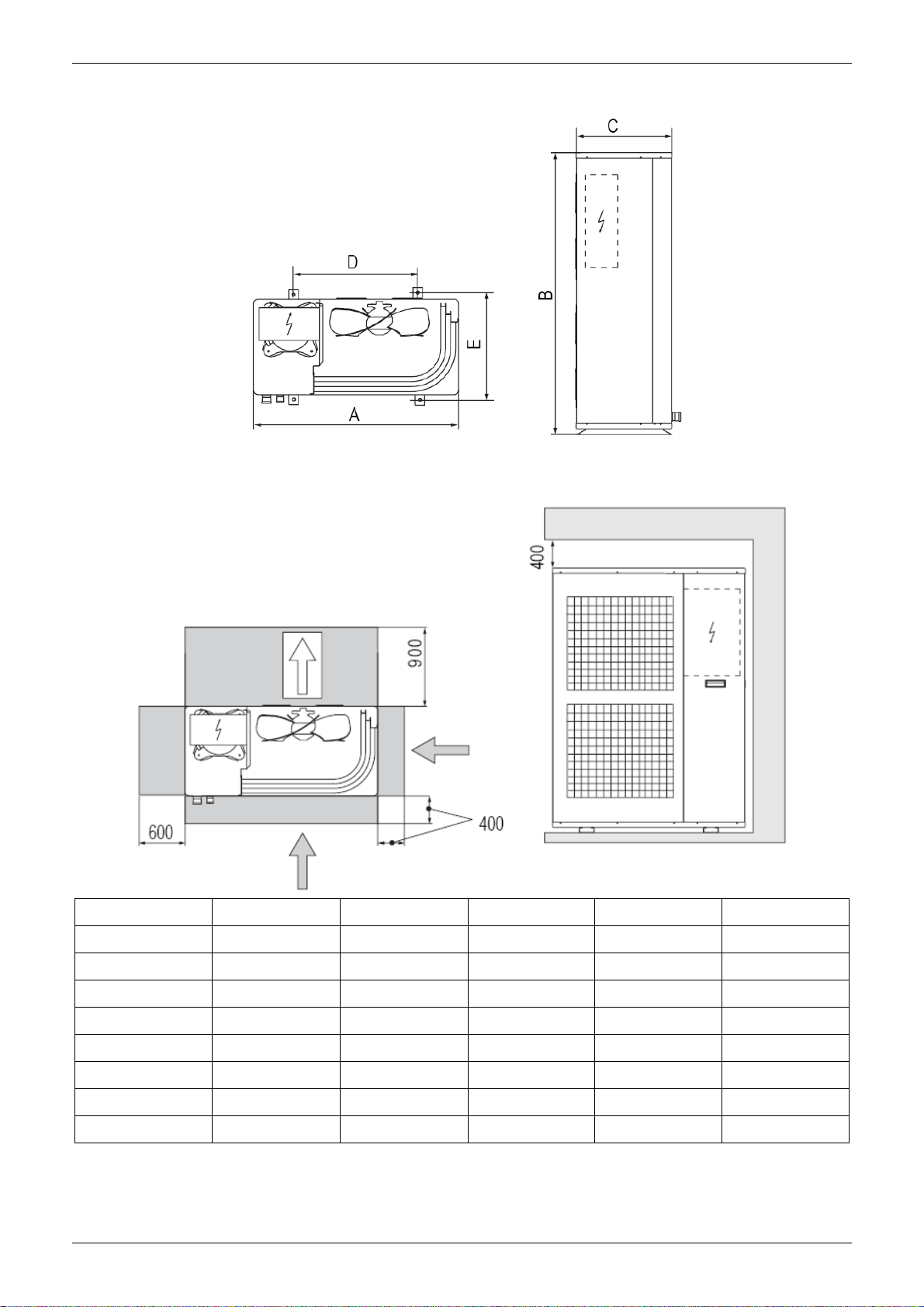
3.1 Choice of installation site
Before installing the unit, agree with the customer the site where it will be installed, taking the following
points into consideration:
- check that the fixing points are adequate to support the weight of the unit;
- pay scrupulous respect to safety distances between the unit and other equipment or structures to ensure
that air entering the unit and discharged by the fans is free to circulate.
3.2 Positioning
Before handling the unit, check the capacity of the lifting equipment used, respecting the instructions on the
packaging.
To move the unit in the horizontal, make appropriate use of a lift truck or similar, bearing in mind the weight
distribution of the unit. To lift the unit, insert tubes long enough to allow positioning of the lifting slings and
safety pins in the feet on the unit.
To avoid the slings damaging the unit, place protection between the slings and the unit. Position the unit in
the site indicated by the customer. Place either a layer of rubber (min. thickness 10 mm) or vibration damper
feet (optional) between the base and support surface. Fix the unit, making sure it is level and that there is
easy access to hydraulic and electrical components. If the site of installation is exposed to strong winds, fix
the unit adequately to the support surface using tie rods if necessary. If a heat pump unit is being installed,
make sure the condensate is drained using the drain hose supplied as standard. Prevent leaves, branches
or snow from accumulating around the unit. These could reduce the efficiency of the unit.
66 Installation
Page 69

MCAC-TSM-2008-02 Installation of Outdoor Unit
3.3 Service space
Dimension A B C D E
MGC-F05W/N1 990 966 354 624 366
MGC-F07W/N1 990 966 354 624 366
MGC-F09W/N1 940 1245 360 600 376
MGC-F10W/N1 940 1245 360 600 376
MGC-F10W/SN1 940 1245 360 600 376
MGC-F12W/SN1 1070 1249 420 698 430
MGC-F14W/SN1 1070 1249 420 698 430
MGC-F16W/SN1 1070 1249 420 698 430
Installation 67
Page 70

Hydraulic Connection MCAC-TSM-2008-02
4. Hydraulic Connection
The choice and installation of components is the responsibility of the installer who should follow good
working practice and current legislation. Before connecting the pipes, make sure they do not contain stones,
sand, rust, dross or other foreign bodies which might damage the unit. Construction of a bypass is
recommended to enable the pipes to be washed through without having to disconnect the unit (see drain
valves). The connection piping should be supported in such a way as to avoid it weighing on the unit. It is
recommended that the following devices are installed in the water circuit of the evaporator:
1. Two pressure gauges with a suitable (inlet and outlet)
2. Two vibration damper joints (inlet and outlet)
3. Two gate valves (normal inlet and calibrating in outlet)
4. A flow switch (inlet) or a differential pressure switch (inlet-outlet).
5. Two thermometers (inlet and outlet).
6. An inlet filter as close as possible to the evaporator and positioned to allow easy access for routine
maintenance.
7. An energy-saving water tank.
8. Additional pump.
9. The connecting line of flow switch, which mounted outside the unit, should be connected in series with
the pressure-difference
No Name No Name No Name
1 Pressure gauge 7 Pump 13 Temperature sensor
2 Vibration damper joint 8 Safety valve 14 Differential pressure switch
3 Gate valve 9 Air vent 15 Drain/chemical washing valve
4 Calibrating valve 10 Expansion tank 16 Plate heat exchanger
5 Flow switch 11 Mesh filter 17 Additional pump
6 Thermometer 12 Auto-water replenishing 18 Additional pump
If the installation requires a useful head higher than that obtained by installing a pump assembly and storage
tank, it is recommended that an additional pump is installed on the unit. Provided the additional pump
installed inside of unit (only model 12/14/16kW can be installed inside of unit), the pump must connected
68 Installation
Page 71

MCAC-TSM-2008-02 Hydraulic Connection
close to plate heat exchanger. Provided the pump installed outside of unit, the pump shall be connected at
water pipe’s outlet. The pump can be easily installed on the unit by removing the pump connection pipe.
Important
1) The chillers must be provided with a filling/top-up system connected to the return line and a drain cock
in the lowest part of the installation. Installations containing anti-freeze or covered by specific legislation
must be fitted with hydraulic disconnections.
2) The manufacturer is not liable for obstruction, breakage or noise resulting from the failure to install filters
or vibration dampers. Particular types of water used for filling or topping up must be treated with
appropriate treatment systems. For reference values, see the table.
PH 6-8
Electrical conductivity
Chlorine ions less than 50 ppm
Sulphuric acid ions less than 50 ppm
Total iron less than 50 ppm
Alkalinity M less than 50 ppm
Total hardness less than 50 ppm
Sulphur ions none
Ammonia ions none
Silicon ions less than 30 ppm
less than 200 mV/cm (25°C)
Filling the installation
- Before filling, check that the installation drain cock is closed.
- Open all installation and terminal air vents.
- Open the gate valves.
- Begin filling, slowly opening the water filling cock outside the unit
- When water begins to leak out of the terminal air vent valves, close them and continue filling until the
pressure gauge indicates a pressure of 1.5 bars.
Emptying the installation
- Before emptying, place the mains switch in the“off” position
- Make sure the installation fill/top-up water cock is closed
- Open the drain cock outside the unit and all the installation and terminal air vent valves.
Installation 69
Page 72

Hydraulic Connection MCAC-TSM-2008-02
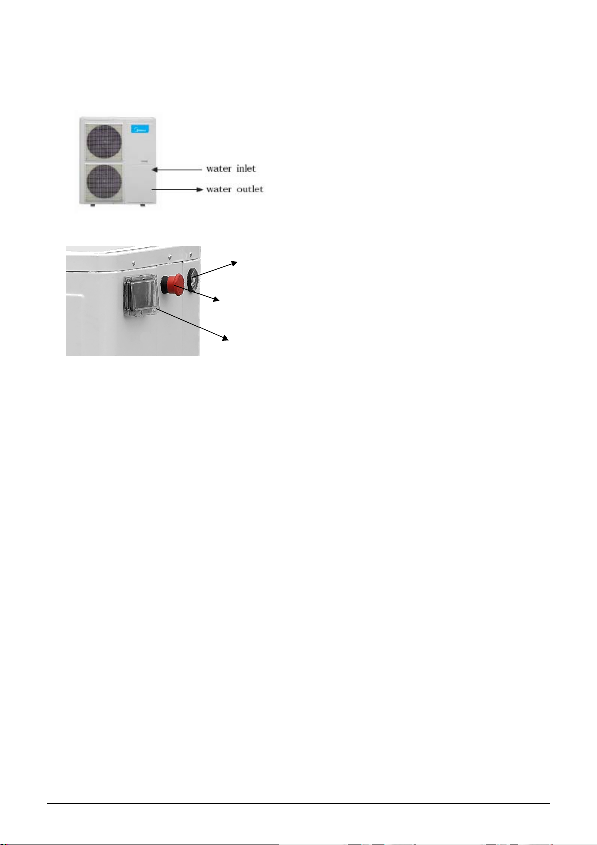
Size and position of connections
Model
MGC-F05W/N1 70 118 196 328 122 170 R1 G1/2 G1/2
MGC-F07W/N1 70 118 196 328 122 170 R1 G1/2 G1/2
MGC-F09W/N1 76 107 217 305 145 107 R5/4 G1/2 G1/2
MGC-F10W/N1 76 107 217 305 145 107 R5/4 G1/2 G1/2
MGC-F10W/SN1 76 107 217 305 145 107 R5/4 G1/2 G1/2
MGC-F12W/SN1 78 84 174 297 148 148 R5/4 G1/2 G1/2
MGC-F14W/SN1 78 84 174 297 148 148 R5/4 G1/2 G1/2
MGC-F16W/SN1 78 84 174 297 148 148 R5/4 G1/2 G1/2
A
(mm) B (mm) C (mm) D (mm)E (mm)F (mm)
Water
inlet/outlet (Ø)
Auto-water
replenishing (Ø)
Security
discharge (Ø)
Important
a) The installation must be filled to a pressure of between 1 and 2 bars.
b) It is recommended that this operation be repeated after the unit has been operating for a number of
hours. The pressure of the installation should be checked regularly and if it drops below 1 bar, the water
content should be topped-up.
c) Check the hydraulic tightness of joints.
d) If the fluid in the circuit contains anti-freeze, it should not be allowed to drain freely as it is pollutant.
e) It should be collected for possible reuse.
f) When draining after heat pump operation, take care as the water may be hot (up to 50℃).
70 Installation
Page 73

MCAC-TSM-2008-02 Electrical Connection
5. Electrical Connection
The MGC chillers leave the factory already wired, and require the installation of an omnipolar thermal
overload switch, a lockable mains disconnecting switch for the connection to the mains power supply, and
the connection of the flow switch to the corresponding terminals. All the above operations must be carried
out by qualified personnel in compliance with the legislation in force.
For all electrical work, refer to the electrical wiring diagrams in this manual. You are also recommended to
check that the characteristics of the mains electricity supply are adequate for the absorptions indicated in the
electrical characteristics table below, also bearing in mind the possible use of other equipment at the same
time.
Important
Power to the unit must be turned on only after installation work (hydraulic and electrical) has been
completed.
All electrical connections must be carried out by qualified personnel in accordance with legislation
in force in the country concerned.
Respect instructions for connecting phase, neutral and earth conductors.
The power line should be fitted upstream with a suitable device to protect against short-circuits and
leakage to earth, isolating the installation from other equipment.
Voltage must be within a tolerance of ±10% of the rated power supply voltage for the unit (for three
phase units, the unbalance between the phases must not exceed 3%).If these parameters are not
respected, contact the electricity supply company.
For electrical connections, use double insulation cable in conformity with current legislation in the
country concerned
An omnipolar thermal overload switch and a lockable mains disconnecting switch, in compliance
with the CEI-EN standards (contact opening of at least 3mm), with adequate switching and residual
current protection capacity based on the electrical data table shown below, must be installed as
near as possible to the appliance
The devices on the unit must be lockable. An efficient earth connection is obligatory. Failure to
earth the appliance absolves the manufacturer of all liability for damage.
In the case of three phase units, ensure the phases are connected correctly.
Do not use water pipes to earth the unit.
Electrical Panel
The electrical panel is located inside the unit at the top of the technical compartment where the various
components of the refrigerant circuit are also to be found.
To access the electrical panel, remove the front panel of the unit by undoing the screws.
Installation 71
Page 74

Electrical Connection MCAC-TSM-2008-02
Electrical Panel Layout
Electrical Power Connection
For the functional connection of the unit, bring the power supply cable to the electrical panel inside the unit
and connect it to terminals L-N and
respecting the (L) phase, (N) neutral and earth in the case of
single phase units (220-240V~50Hz), or L1-L2-L3 phases, N neutral and PE earth in three phase units
(380~415V-3N-50Hz).
Auxiliary Connection
All terminals referred to in the explanations below are to be found on the terminal board inside the electrical
panel and described as “installer terminals”.
Remote start up and shut down
To fit a remote on/off device, the jumper must be replaced with a switch connected to terminals 4 and 5 on
the installer terminal board. For timed operation, connect a daily or weekly timer between terminals 4 and 5.
Remote keyboard kit
The remote keyboard kit can be used to display all unit functions and access the parameters of the
electronic board from a point located at some distance from the unit itself.
72 Installation
Page 75

MCAC-TSM-2008-02 Electrical Connection
It consists of a remote control module.
To install the kit, proceed as follows:
- disconnect the power supply and then access the inside f the electrical panel;
- connect the remote control module with 3 wires to terminals 15, 16 and 17 on the installer terminal board:
connect terminal 15 to terminal Black/gnd on the module;
connect terminal 16 to terminal Blue/signal on the module;
connect terminal 17 to terminal Red/+12v on the module;
Important
To avoid interference due to magnetic fields, the use of shielded cable is recommended. The cable should
not be more than 100m long.
The Specification of Power:
Type MGC-F05W/N1 MGC-F07W/N1 MGC-F09W/N1 MGC-F10W/N1
Power 220~240-1-50 220~240-1-50 220~240-1-50 220~240-1-50
Circuit breaker/fuse (A) 25/20 30/25 40/25 40/35
Power wiring (mm2) 3×2.5 3×2.5 3×4.0 3×4.0
Ground wiring (mm2) 2.5 2.5 4.0 4.0
Outdoor /Indoor connecting wiring (mm2 ) 1.0 1.0 1.0 1.0
Type MGC-F10W/SN1 MGC-F12W/SN1 MGC-F14W/SN1 MGC-F16W/SN1
Power 380~415-3-50 380~415-3-50 380~415-3-50 380~415-3-50
Circuit breaker/fuse (A) 25/15 25/15 25/15 30/20
Power wiring (mm2) 5×2.5 5×2.5 5×2.5 5×4.0
Ground wiring (mm2) 2.5 2.5 2.5 4.0
Outdoor /Indoor connecting wiring (mm2 ) 1.0 1.0 1.0 1.0
Important
The power cord type designation is H07RN-F.
Connecting cable between indoor unit and outdoor unit shall be approved poly-chloroprene sheathed flexible
cord, type designation H07RN-F or heavier cord.
The means for disconnection from a power supply shall be incorporated in the fixed wiring and have an air
gap contact separation of at least 3mm in each active(phase) conductors.
Installation 73
Page 76

Checking and Starting Up the Unit MCAC-TSM-2008-02
6. Checking and Starting Up the Unit
6.1 Preparing for first start up
Restarting after shutting down for long periods
The chiller must be started up for the first time by the Technical Service. Before starting up the chillers, make
sure that:
- All safety conditions have been respected
- The chiller is adequately fixed to the surface it rests on
- Functional distances have been respected;
- Hydraulic connections have been carried out as indicated in the instruction manual
- The water circuit is filled and vented. When draining after heat pump operation, take care as the water
may be hot;
- The water circuit valves are open
- Electrical connections have been carried out correctly
- Voltage is within a tolerance of 10% of the rated voltage for the unit
- The unit is correctly earthed
- All electrical and hydraulic connections are tight and have been completed correctly.
Important
The unit must be started up for the first time with standard settings. Set point values may be modified only
after testing has been completed. Before starting up, power the unit for at least two hours by switching QF1
and QS1 to ON and setting the control panel “HSW7”to OFF to allow the oil in the compressor sump to heat
up.
6.2 Starting up for the first time (after two hours)
Before activating the chiller:
- Make sure the main remote switch QF1 is in the OFF position;
- Make sure the remote secondary switch SA2 is in the OFF or STANDBY position
- Make sure the remote keyboard A6 (if present) is set to OFF
To complete the electrical connections:
- Remove the inspection panel by unscrewing the five screws
74 Installation
Page 77

MCAC-TSM-2008-02 Checking and Starting Up the Unit
- Use grommet A for the electrical power cable and grommet B for the other external wires.
- Replace the inspection panel.
- Position the main switch QF1 (outside the unit) in the “ON” position.
- The “POWER” LED on the control panel “ST542” comes on to signal that voltage is present.
6.3 Activating and deactivating the unit
-Set the remote keyboard “A6” (if present) to ON.
- To ACTIVATE and DEACTIVATE the COOLING and HEATING functions, use the "ST542" control panel or
the remote keyboard "A6" if present.
During this phase, if the following indications appear on the display, follow the instructions:
Important
- E20 check water flow rate and differential pressure switch.
To access the control panel, open the door:
- remove the screw 1 and screw 2;
- lift t he door 3.
Installation 75
Page 78

Running and Maintenance MCAC-TSM-2008-02
7. Running and Maintenance
7.1 Operating characteristics
Set point in cooling
(factory set) = 10°C, Hysteresis = 3°C.
The compressor starts with water temperatures above 13°C.
The compressor shuts down with water temperatures of less than 10°C.
Set point in heating
(factory set) = 45°C, Hysteresis = 3°C.
The compressor starts with water temperatures below 42°C.
The compressor shuts down with water temperatures above 45°C.
In the event of a temporary power failure, when power returns, the mode set previously will be retained in the
memory.
Compressor start up delay
Two functions prevent the compressor from starting up too frequently
- Minimum time since last shut-down 180 seconds.
- Minimum time since last start-up 360 seconds.
Pump
The electronic board includes a pump control output. The pump starts when the assembly is powered up
and at least 120 seconds before the compressor starts up and stops 120 seconds after the assembly shuts
down. After the first 120 seconds o f pump operation when the water flow is at full speed, the water flow
alarm functions are activated (differential pressure switch and flow switch). With a pump connected to
terminals PL and PN on the installer terminal board.
Fan speed control
For correct operation of the unit with different outside temperatures, the microprocessor controls the fan
speed based on the pressure reading from the pressure probe, thus enabling heat exchange to be increased
and/or decreased, maintaining the condensing or evaporation temperature practically constant.
The fan functions independently of the compressor.
Frost prevention alarm
To prevent the water freezing and damaging the plate heat exchanger, the microprocessor shuts down the
compressor if the temperature measured by the heat exchanger outlet temperature sensor is less than 3°C.
The frost prevention temperature set point can be modified by an authorized service centre only and only
after verifying that the water circuit contains antifreeze. Tripping of this alarm shuts down the compressor but
not the pump, which remains active. To reset normal functions, the outlet water temperature must rise to
more than +15°C. Reset is manual.
Water flow alarm
The microprocessor provides for management of a water flow alarm controlled by a differential pressure
switch fitted as standard on the appliance to be installed on the water delivery piping.
This safety device may trip after the first 120 seconds of pump operation when the water flow is up to speed.
Tripping of this alarm shuts down the compressor but not the pump, which remains active. To reset normal
functions, the alarm contact must be deactivated for at least five seconds.
When electrical current exceeds to setting value and condenser temperature over than 65°C, system will
shut down, but not returns to normal operation until the condenser temperature decreased less than 52°C. If
phase sequence were detected error, please re-input power, and then the system will turn normal.
76 Installation
Page 79

MCAC-TSM-2008-02 Running and Maintenance
7.2 Routine maintenance
Never perform any cleaning operations before having disconnected the unit from the mains power supply.
Regular maintenance is fundamental to maintain the efficiency of the unit both in terms of operation and
energy consumption. The Technical Assistance Service maintenance plan must be observed, with an
annual service which includes the following operations and checks:
- Filling of the water circuit
- Presence of air bubbles in the water circuit
- Efficiency of safety devices
- Power supply voltage
- Power input
- Tightness of electrical and hydraulic connections
- Condition of the compressor contactor
- Efficiency of the plate heat exchanger heater
- Checking of operating pressure, superheating and sub cooling
- Efficiency of compressor heater
- Cleaning of finned coil (*)
- Cleaning of fan grills
- Cleaning of condensate drain pan.
(*) For“Heat pump” appliances, the checks are to be performed quarterly.
For units installed near the sea, the intervals between maintenance should be halved.
7.3 Extraordinary maintenance
Chemical washing
Chemically wash the plate heat exchanger after every 3 years of operation.
Refrigerant gas content
The chillers are filled with R410a refrigerant gas and tested in the factory. In normal conditions, there should
be no need for the Technical Assistance Service to intervene to check the refrigerant gas. However, over
time, small leaks may develop at the joints leading to loss of refrigerant and draining of the circuit, causing
the unit to function poorly. In this case, the leaks of refrigerant must be identified and repaired and the
refrigerant circuit refilled. Proceed as follows:
- Empty and dry the entire refrigerant circuit using a vacuum pump connected to the low and high
pressure tap until the vacuometer reads about 10Pa. Wait a couple of minutes and check that this value
does not rise to more than 200Pa
- Connect the refrigerant gas cylinder or a filling cylinder to the low pressure line pressure gauge
connection.
- Fill with the quantity of refrigerant gas indicated on the rating plate of the unit.
- Always check the superheating and sub cooling values. In the nominal operating conditions for the
appliance, these should be between 5 and 10°C and between 4 and 8°C respectively.
- After a couple of hours of operation, check that the liquid indicator indicates circuit dry (dry-green)
Important
In the event of partial leaks, the circuit must be completely emptied before being refilled
The R410a refrigerant must only be filled in the liquid state. Operating conditions other than nominal
conditions may produce considerably different values.
Seal testing or identification of leaks must only be carried out using R410a refrigerant gas, checking with a
suitable leak detector.
Installation 77
Page 80

Running and Maintenance MCAC-TSM-2008-02
Prohibition
1. The refrigerant circuit must not be filled with a refrigerant other than that indicated of specification.
2. The use of a different refrigerant may cause serious damage to the compressor.
3. Oxygen, acetylene or other inflammable or poisonous gases must never be used in the refrigerant
circuit as they may cause explosion or poisoning.
7.4 Shutting down for long periods
If it is previewed not to use the machine for long periods
After deactivating the chiller:
- Make sure the remote switch SA 2 is in the "Standby" position, or alternatively disconnect the unit from the
power supply.
- Make sure the remote keyboard (if present) or the ST542 is set to “OFF”.
- Position QF and QS on OFF
- Deactivate the indoor terminal units by placing the switch of each unit in the “OFF” position.
- Close the water valves.
Important
If there is a possibility that the outside temperature may drop below zero, there is the risk of freezing.
The water circuit MUST BE EMPTIED AND SHUT OFF POWER (when draining after heat pump operation
take care as the water may be hot) or antifreeze must be added in the proportion recommended by the
manufacturer.
78 Installation
Page 81

MCAC-TSM-2008-02 Running and Maintenance
Part 4
Controller
1. Standard Controller........................................................80
Installation 79
Page 82

Standard Controller MCAC-TSM-2008-02
1. Standard Controller
ST542
It is built-in with the chiller at the factory.
The front panel of the device functions as the user interface and is used to perform all operations relating to
the device.
1.1 Introduction of Keys
There are 4 keys on the front panel. Each key has:
● A “direct” action (indicated on the key).
● An “associated” function (indicated on the front panel of the device beside the key).
● A “combined” action involving two keys.
Keys and associated functions
Press and hold
[press for about
3 seconds]
[Manual defrost
activation]
[Local ON/OFF]
[Change mode]
Key Description key
UP
(UP)
DOWN
(DOWN)
Esc(ape)
Output
(Without saving
new settings)
Set
Confirm
(save new settings)
• Increases a value
• Goes to the next label
• Decreases a value
• Goes to the previous label
• Exit without saving new settings
• Go back to previous level
• Confirms value/ exit and save
new settings
• Move to next level (open folder,
subfolder, parameter, value)
• Open State Menu
Press once
(press and release)
Key
[associated function]
disp [Main display]
ALL Alarm acknowledgment
1.2 Introduction of “Programming” menu and “State” menu
Programming menu
PAr CF Ui St ……. Al Parameters
FnC dEF tA St CC EUr Functions
PASS
EU Eu00 ……. ……. ……. …….
Password
chapter (folder FnC)
“States” menu
From the states menu you can view values for each resource.
For some resources, a "dynamic" view is possible.
• For example, when declared as not present / probe not configured (see System Configuration chapter
80 Controller
See Functions
Page 83

MCAC-TSM-2008-02 Standard Controller
(folder Par/CF), parameter CF01=0), analogue input AI2 will not be displayed.
• For example the hours of functioning of compressor 2 - CP02 - not available on single compressor
machines.
Label Visibility Description Change
Ai Ai1 Ai2 Ai3 Ai4 // // Dynamic Analogue inputs //
di di1 di2 di3 di4 di5 // Dynamic Digital inputs //
AO AO1 AO2 AO3 // // // Dynamic Analogue outputs //
dO dO1 dO2 dO3 dO4 dO5 dO6 Dynamic Digital outputs //
CL HOUr dAtE yeaR Clock Yes
AL Er00 …….. …….. …….. …….. Er99 Dynamic Alarms //
SP Value // // // // // Set points(set) Yes
Sr Value // // // // // Real set point //
Hr CP01 CP02 PU01 PU02 // // Dynamic Running time(hours× 10) compressor/pumps Yes
1.3 Setting Service Parameters
LIST OF ACCESSIBLE PARAMETERS
Parameter Description Unit of measure
CnF*
CP
FAn
ALL
PUP
Fro
dFr
Machine configuration parameters value
Compressor parameters value
Fan parameters value
Alarm parameters value
Pump parameters value
Frost parameters value
Defrost parameters value
1) Local On/OFF
Device ‘ON’ -->‘OFF’
Device ‘OFF’ -->‘ON’
Controller 81
Page 84

Standard Controller MCAC-TSM-2008-02
NOTE:
The local ON/OFF function is deactivated if the device has been turned OFF remotely or if a digital input is
configured as a remote ON/OFF.
Remote on/standby and cooling / heating possibilities
Remote control of the unit can be done by a voltage free contact. Depending on the setting on the digital
controller, the unit will operate in cooling or in heating mode.
Procedure
a. Connect the cable to the appropriate terminals as shown or the wiring diagram.
b. Fix the cable with cable ties to the cable tie mountings to ensure strain relief.
NOTE:
The remote has priority and controls on/standby operation and change over operation.①
If you want to use ST542 to control cooling/heating neither the remote, you must to set the parameter ②
CF26 from “-14” to “0”.Please view parameter (folder PAr).
82 Controller
Page 85

MCAC-TSM-2008-02 Standard Controller
2) Select Operating Mode
There are three different operating modes:
• Standby mode (StbY)
• Heat mode
• Cooling mode
Instructions are provided below on how to change the operating mode.
Controller 83
Page 86

Standard Controller MCAC-TSM-2008-02
3) Select the Clock(CL)
84 Controller
Page 87

MCAC-TSM-2008-02 Standard Controller
4) Modifying a parameter
Instructions are provided below on how to change a machine parameter. By way of example, let’s look at the
CF configuration parameters folder, parameter CF26 (folder PAr/CF/CF26).
Controller 85
Page 88

Standard Controller MCAC-TSM-2008-02
5) Set the set point(SP)
By way of example, we will change the set point value in COOL mode by 12.0 degrees centigrade to12.5
degrees centigrade.
86 Controller
Page 89

MCAC-TSM-2008-02 Standard Controller
Controller 87
Page 90

Standard Controller MCAC-TSM-2008-02
6) View and Reset compressor/pump time
Example display and reset time (hours x10) for Pump 2
Press the set key from the main display
The label Ai will appear on the display. Use the UP
and DOWN keys to scroll the other labels until you find
the Hr label.
Press the set key to view the first label - which in this case
is the running time for compressor 1 (CP01)
Scroll with the UP and DOWN keys to view (if the relative
resources are present) the running time for compressor 2
(CP02) the pump running time (PU01, PU02)/Press the
set key to view the pump running time PU02.
88 Controller
Page 91

MCAC-TSM-2008-02 Standard Controller
The tens of hours of functioning are 2. (Hours expressed
in tens: 2 means 20 hours of operation).
To clear pump running time PU02, press and hold
the [set] key.
To reset the hours of functioning of pump PU02,
press and hold [set].
Note: Repeat the procedure described to reset the
hours of functioning of the other resources.
------------------------------------Press the esc key to go back to the main display.
7) Reset alarm log (folder EUr)
Press [esc + set] in the main screen.
The label ‘PAr’ will appear. Scroll with ‘UP’ and ‘DOWN’ to find the ‘FnC’ label. Press ‘set’. The label ‘dEF’ will appear. Scroll
with ‘UP’ and ‘DOWN’ to find the ‘EUr’ label.
Press the “set” key for 3 seconds [set]
Keys-combined action
Symbol [function
associated to
the combined
pressing of the keys]
Combination
Keys
The ‘YES’= label appears to indicate that the alarm log has
been deleted.
Combined pressing
of keys Press once
(press and release
[UP
(UP)
+
DOWN
(DOWN)]
[Esc+SETPOINT]
[associated function] [Menu] / Comments
[Manual reset]
See Manual alarm
acknowledgment and
reset section
[Open programming
menu]
[Programming menu]
Controller 89
Page 92

Standard Controller MCAC-TSM-2008-02
8) Manual alarm acknowledgment and reset
Alarm messages blink. How to acknowledge an alarm is explained below.
All error messages are shown in the AL folder (see state Menu)
An error message will be shown,
alternating
with the error alert and the main
display.
The ALARM LED will be
permanently on.
An error can be acknowledged
by pressing any key once.
After pressing any key, the
alarm LED will start to blink.
MANUAL RESET
To manually reset an alarm,
press the “up” and “down” keys
together [UP+DOWN]
- - - - - - - - N.B: resetting an active alarm*
will save the alarm in the AL
folder (see state Menu).
* i.e. manual reset (alarm)
90 Controller
Page 93

MCAC-TSM-2008-02 Standard Controller
The device will return to the
main display.
9) LEDs and Display
The display has 18 icons (LEDs) split into 3 categories (+ decimal point):
• Decimal point
• States and Operating Modes
• Values and Units of Measure
• Loads
Display
Values of up to 4 figures or 3 figures plus a sign can be displayed.
LED: decimal point
Values are always shown in tenths of a degree/bar.
At every change of season, make sure the operating conditions fall within the limits specified in the table of
technical data. Check that the compressor current input is less than the maximum indicated in the table of
technical data. In three-phase models, check that the noise levels of the compressor are not abnormal.
If this is the case, reverse one phase. Make sure the voltage is within the established limits and that, for
three phase units, the unbalance its and that, for three phase units, the unbalance between the phases is
less than 3%. Check that the cover is closed again following the setting procedure. Heating and cooling are
activated and deactivated via the control panel.
10) Alarm Display (AL)
Controller 91
Page 94

Standard Controller MCAC-TSM-2008-02
92 Controller
 Loading...