

Midea MGBT-F60W/RN1, MGBT-F120W/RN1, MGBT-F180W/RN1, MGBT-F250W/RN1, MGBT-D25W/RN1 Series Manual
...
MCAC-ATSM-2014-09 Aqua tempo power series tropical air-cooled scroll chiller 50Hz
Content
Part 1 System outline ........................................................................................................................ 1
1. General outline .......................................................................................................................... 3
2. Pipe connection drawing .......................................................................................................... 26
3. Refrigeration system drawing ................................................................................................... 32
4. Wiring diagram ........................................................................................................................ 36
5 Networking communication wiring diagram .............................................................................. 42
6.Exploded view .......................................................................................................................... 48
Part 2 Capacity tables and control system ........................................................................................ 74
1. Capacity tables ......................................................................................................................... 75
2 Control system .......................................................................................................................... 89
Part 3 Trouble shooting ................................................................................................................. 138
1. Malfunction & protection codes ............................................................................................. 139
2 Troubles and Solutions ............................................................................................................ 145
3 Typical malfunction solutions .................................................................................................. 147
Part 4 Installation ......................................................................................................................... 156
1. Transportation and foundation installation............................................................................. 157
2. Water system installation ...................................................................................................... 165
3. Installation of water system pipeline ...................................................................................... 168
4. Wiring installation ................................................................................................................. 178
5. Trial run ................................................................................................................................. 182
Part 5 Maintenance ...................................................................................................................... 185
1. About maintenance ............................................................................................................... 186
2. Periodical check ..................................................................................................................... 188
Part 6 Wired controller.................................................................................................................. 190
1.1 KJRM-120D/BMK-E(Standard) .............................................................................................. 191
1.2 KJR-120A/MBTE(Optional) ................................................................................................... 200
Appendix ...................................................................................................................................... 209
※ Manufacture reserves the right to discontinue, or change at any time, specifications or designs without notices and
without incurring obligations
Content 1


MCAC-ATSM-2014-09 Aqua tempo power series tropical air-cooled scroll chiller 50Hz
Part 1 System outline
Part 1 System outline ........................................................................................................................ 1
1. General outline .......................................................................................................................... 3
1.1 Nomenclature ................................................................................................................................................................ 3
1.2 Products list .................................................................................................................................................................... 3
1.3 External appearance ...................................................................................................................................................... 4
1.4 Features ......................................................................................................................................................................... 5
1.5 Capacity lineup ............................................................................................................................................................... 8
1.6 Specification: MGBT-F25W/RN1, MGBT-D25W/RN1 ..................................................................................................... 9
1.7 Specification: MGBT-F30W/RN1, MGBT-D30W/RN1 ................................................................................................... 11
1.8 Specification: MGBT-F60W/RN1, MGBT-D60W/RN1, MGBT-F120W/RN1 ................................................................... 13
1.9 Specification: MGBT-F180W/RN1, MGBT-F250W/RN1 ................................................................................................ 15
1.10 Electric Characteristics ............................................................................................................................................... 17
1.11 Outlook drawing: MGBT-F25W/RN1, MGBT-D25W/RN1, MGBT-D30W/RN1, MGBT-F30W/RN1 .............................. 18
1.12 Outlook drawing: MGBT-F60W/RN1 .......................................................................................................................... 19
1.13 Outlook drawing: MGBT-D60W/RN1.......................................................................................................................... 20
1.14 Outlook drawing: MGBT-F120W/RN1 ........................................................................................................................ 21
1.15 Outlook drawing: MGBT-F180W/RN1 ........................................................................................................................ 22
1.16 Outlook drawing: MGBT-F250W/RN1 ........................................................................................................................ 24
2. Pipe connection drawing .......................................................................................................... 26
2.1MGBT-F25W/RN1,MGBT-D25W/RN1,MGBT-F30W/RN1,MGBT-D30W/RN1 ................................................................ 26
2.2 MGBT-F60W/RN1 ......................................................................................................................................................... 27
2.3 MGBT-D60W/RN1 ........................................................................................................................................................ 28
2.4 MGBT-F120W/RN1 ....................................................................................................................................................... 29
2.5 MGBT-F180W/RN1 ....................................................................................................................................................... 30
2.6 MGBT-F250W/RN1 ....................................................................................................................................................... 31
3. Refrigeration system drawing ................................................................................................... 32
3.1 MGBT-F25W/RN1, MGBT-D25W/RN1, MGBT-F30W/RN1 ,MGBT-D30W/RN1 ............................................................. 32
3.2 MGBT-F60W/RN1 ......................................................................................................................................................... 32
3.3 MGBT-D60W/RN1 ........................................................................................................................................................ 33
3.4 MGBT-F120W/RN1 ....................................................................................................................................................... 33
3.5 MGBT-F180W/RN1 ....................................................................................................................................................... 34
3.6 MGBT-F250W/RN1 ....................................................................................................................................................... 34
4. Wiring diagram ........................................................................................................................ 36
4.1 MGBT-F25W/RN1, MGBT-D25W/RN1, MGBT-F30W/RN1, MGBT-D30W/RN1 ............................................................. 36
4.2 MGBT-F60W/RN1 ......................................................................................................................................................... 37
1

Aqua tempo power series tropical air-cooled scroll chiller 50Hz MCAC-ATSM-2014-09
4.3 MGBT-D60W/RN1 ........................................................................................................................................................ 38
4.4 MGBT-F120W/RN1 ....................................................................................................................................................... 39
4.5 MGBT-F180W/RN1 ....................................................................................................................................................... 40
4.6 MGBT-F250W/RN1 ....................................................................................................................................................... 41
5 Networking communication wiring diagram .............................................................................. 42
5.1 MGBT-F25W/RN1, MGBT-D25W/RN1, MGBT-F30W/RN1, MGBT-D30W/RN1 ............................................................. 42
5.2 MGBT-F60W/RN1 ......................................................................................................................................................... 43
5.3 MGBT-D60W/RN1 ........................................................................................................................................................ 44
5.4 MGBT-F120W/RN1 ....................................................................................................................................................... 45
5.5MGBT-F180W/RN1 ........................................................................................................................................................ 46
5.6MGBT-F250W/RN1 ........................................................................................................................................................ 47
6.Exploded view .......................................................................................................................... 48
6.1 MGBT-F25W/RN1 ......................................................................................................................................................... 48
6.2 MGBT-D25W/RN1 ........................................................................................................................................................ 50
6.3 MGBT-F30W/RN1 ......................................................................................................................................................... 53
6.4 MGBT-D30W/RN1 ........................................................................................................................................................ 55
6.5 MGBT-F60W/RN1 ......................................................................................................................................................... 58
6.6 MGBT-D60W/RN1 ........................................................................................................................................................ 61
6.7 MGBT-F120W/RN1 ....................................................................................................................................................... 65
6.8 MGBT-F180W/RN1 ....................................................................................................................................................... 68
6.9 MGBT-F250W/RN1 ....................................................................................................................................................... 70
2
MCAC-ATSM-2014-09 Aqua tempo power series tropical air-cooled scroll chiller 50Hz
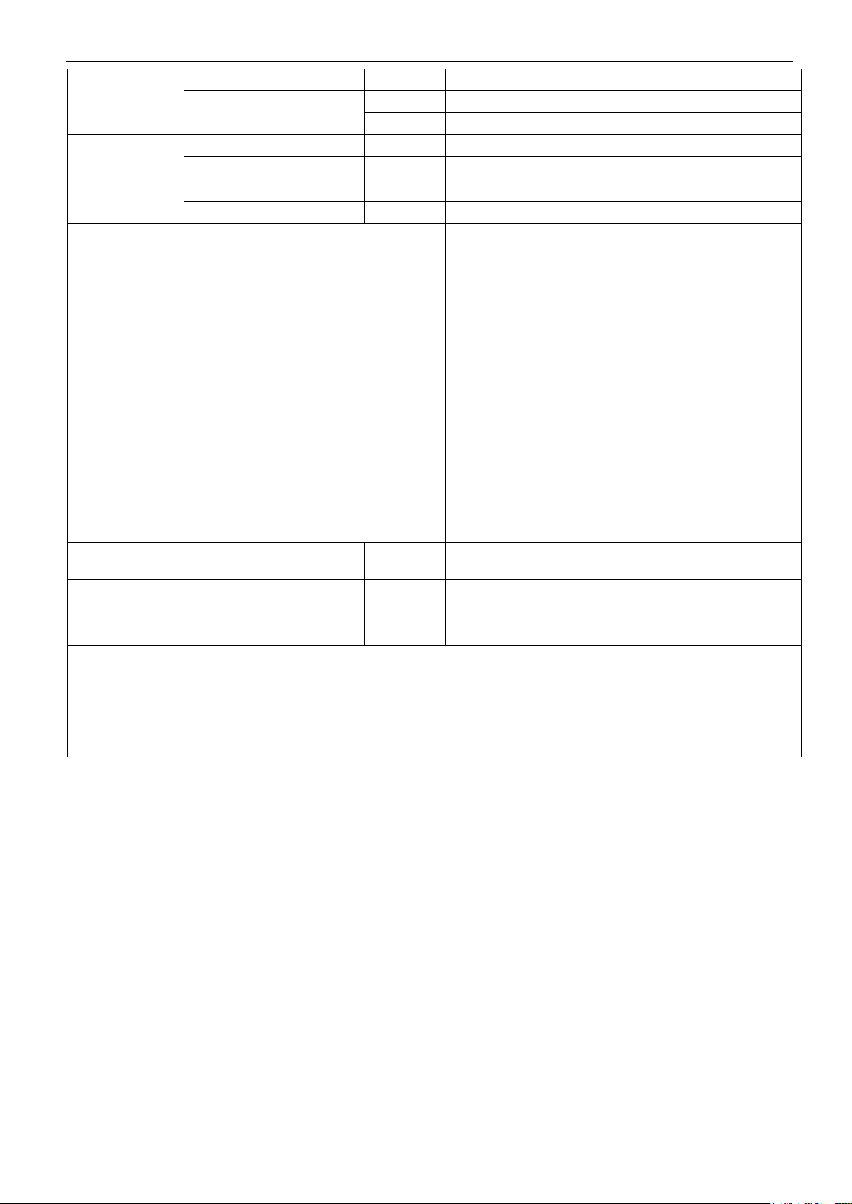
No
Model
Refrigerant
Heat exchanger type
Power supply
Wired controller
1
MGBT-F25W/RN1
R410A
Double pipe
380~415V/50Hz/3Ph
KJRM-120D/BMK-E
2
MGBT-D25W/RN1
KJRM-120D/BMK-E
3
MGBT-F30W/RN1
KJRM-120D/BMK-E
4
MGBT-D30W/RN1
KJRM-120D/BMK-E
5
MGBT-F60W/RN1
Shell and tube
KJRM-120D/BMK-E
6
MGBT-D60W/RN1
KJRM-120D/BMK-E
7
MGBT-F120W/RN1
KJRM-120D/BMK-E
8
MGBT-F180W/RN1
KJRM-120D/BMK-E
9
MGBT-F250W/RN1
KJRM-120D/BMK-E
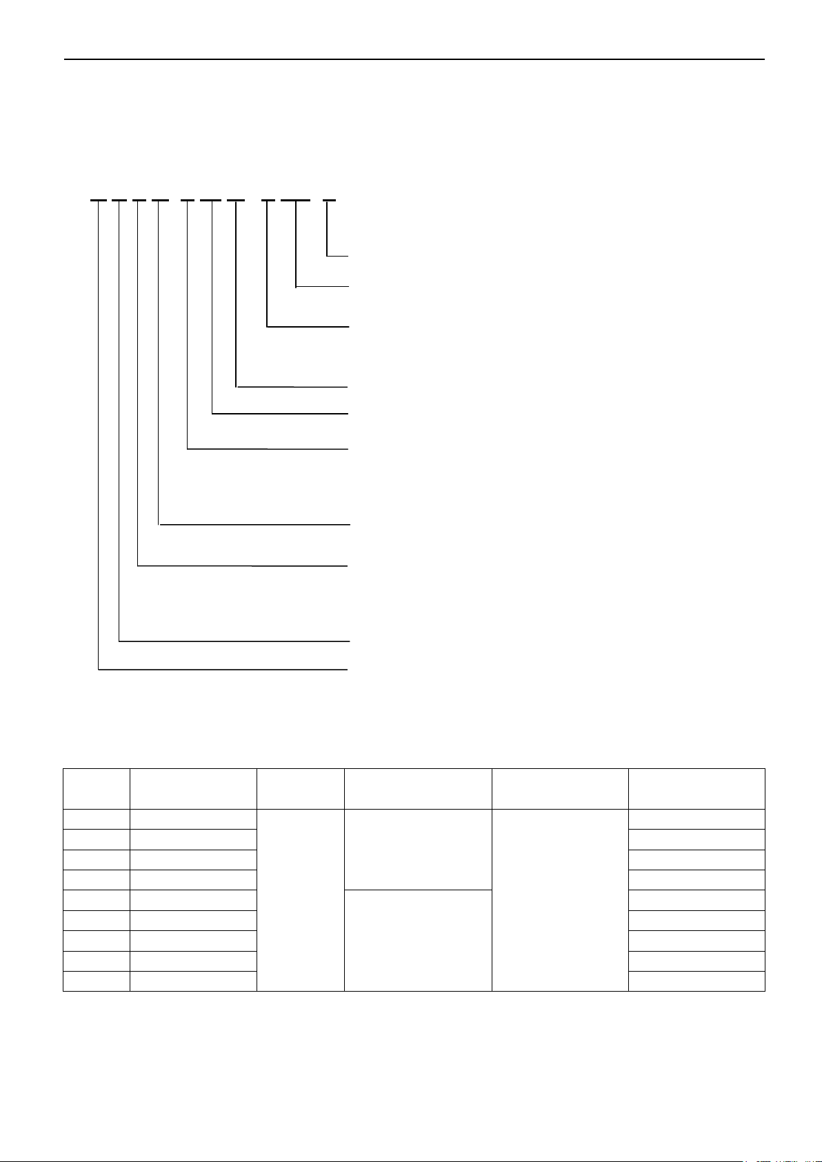
Design Serial Number
Refrigerant type
N1:R410A Omit for R22
Power Supply
R: 380~415V, 50Hz, 3N
D: 220V, 60Hz,3N
Outdoor Unit
Rated cooling capacity (kW)
The special function code
D: Digital scroll
F: Constant feed
V: Inverter system
T: T3 condition
Omit for T1 condition
The heat exchanger type
A: Plate heat exchanger
B: Tube and shell or double pipe heat exchanger
Light chiller system
Midea
1. General outline
1.1 Nomenclature
M G B T - D 30 W / R N1 - A
1.2 Products list
3
Aqua tempo power series tropical air-cooled scroll chiller 50Hz MCAC-ATSM-2014-09
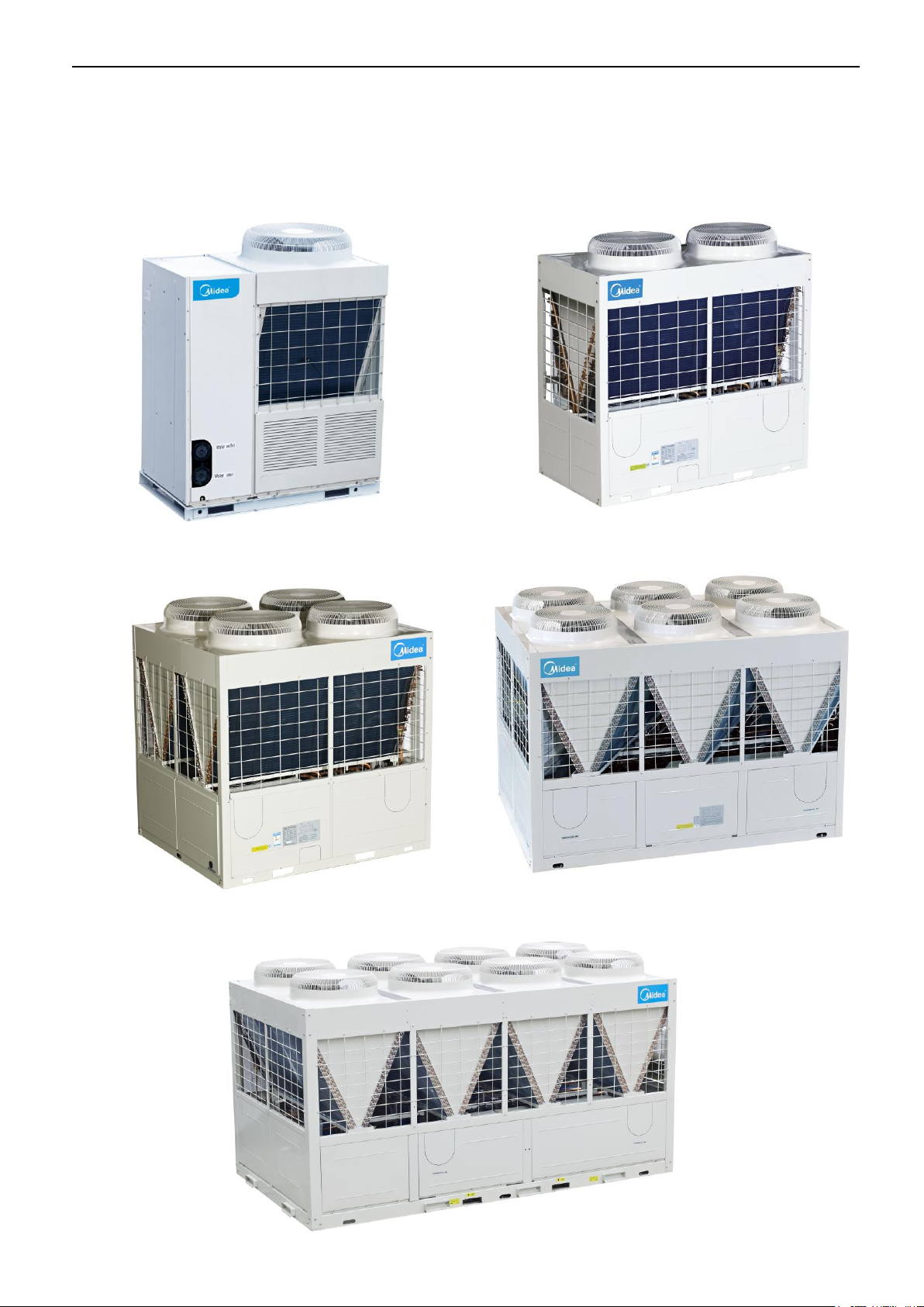
MGBT-F120W/RN1
MGBT-F60W/RN1
MGBT-D60W/RN1
MGBT-F180W/RN1
MGBT-F250W/RN1
MGBT-F25W/RN1
MGBT-D25W/RN1
MGBT-F30W/RN1
MGBT-D30W/RN1
1.3 External appearance
4
MCAC-ATSM-2014-09 Aqua tempo power series tropical air-cooled scroll chiller 50Hz
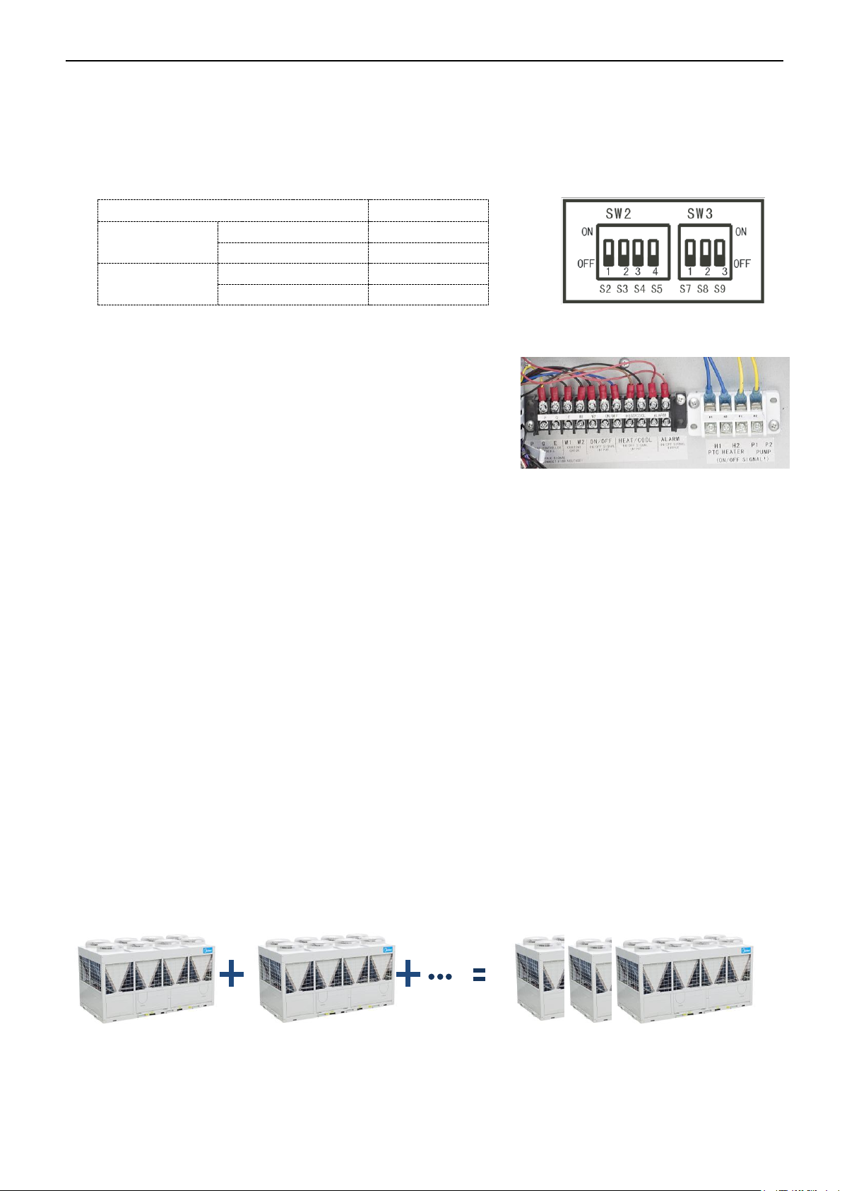
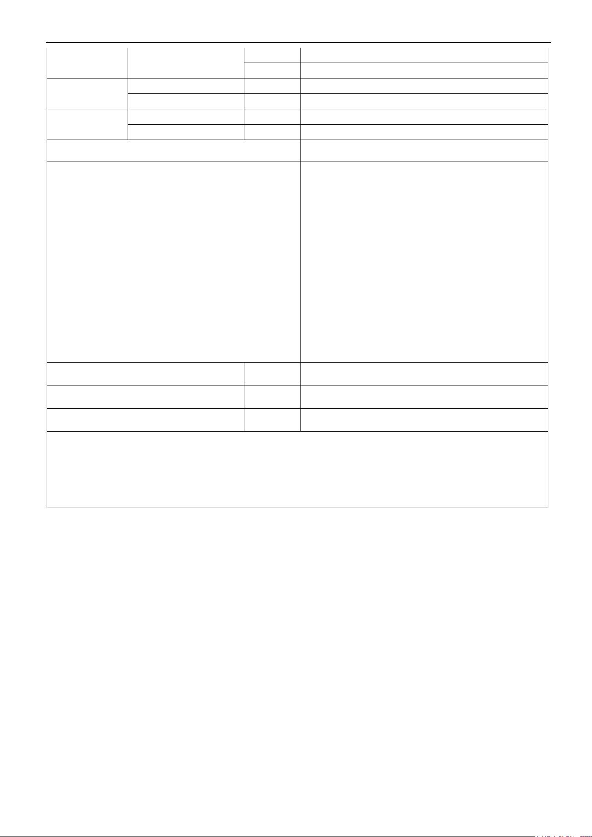
Mode
Outlet water temp.
Cooling(S5
address)
Normally(OFF)
5~17℃
Low water temp.(ON)
0~17℃
Heating(S4
address)
Normally(OFF)
40~50℃
Low water temp. (ON)
22~50℃
Max 8 units
Picture2
2000kW
250kW
250kW
1.4 Features
1). Wide range of outlet water temp. (For MGBT-D60W/RN1, MGBT-F250W/RN1)
Cooling: 5~17˚C (7˚C set in factory), 0~17˚C can be available by switch the S5 on PCB, the antifreeze must be
put into pipeline.
Heating: 40~50˚C (45˚C set in factory), 22~50˚C can be available by switch the address.
2).Humanization remote control (For MGBT-D60W/RN1, MGBT-F250W/RN1)
S7 address on PCB should be switched to ON to realize remote
control, which including: Remote ON/OFF, remote heating and
cooling mode selection, remote alarm. The customer can simply
and conveniently control the module and acquire the running
information on real time in door.
3).Digital scroll technique,new type air-cooled modular chiller system.
Capacity output is controlled depending on controlling compressor to on/off in traditional modular air-cooled
chiller system control. The precision of the control mode is not very good, and the compressor is frequently on
and off, which is very bad for the compressor’s life.
Digital scroll modular air-cooled chiller system breaks traditional design, which is inconceivably designed with
digital scroll compressor and constant scroll compressor parallel connection. The system can achieve linear
capacity output within 0.5%-100% after modules combined, the scope is widest in industry. When the system
operates at the part-load, the system can accurately adjust cooling and heating capacity output basing on
actual requirement of the indoor room.
4). Easy and fast installation
The unit adopts modular design, which can make more units connect together. The unit can combine 16
separate module(equal and less than 65kW) or 8 module(250kW).Cooling(heating) capacity can increase
step by step by 5KW per each time within 15kW-2000kW,meanwhile every separate module can operate as
main unit, also each module can be a slave unit with modules combination, more convenient for design and
installation.
The maximum combination of the system consists of 1 main unit and 15 slave units for 25kW&30kW&60kW
module,1 main unit and 7 slave units for 120kW module, 1 main unit and 4 slave units for 180kW module, 1
main unit and 7 slave units for 250kW module.
5
Aqua tempo power series tropical air-cooled scroll chiller 50Hz MCAC-ATSM-2014-09
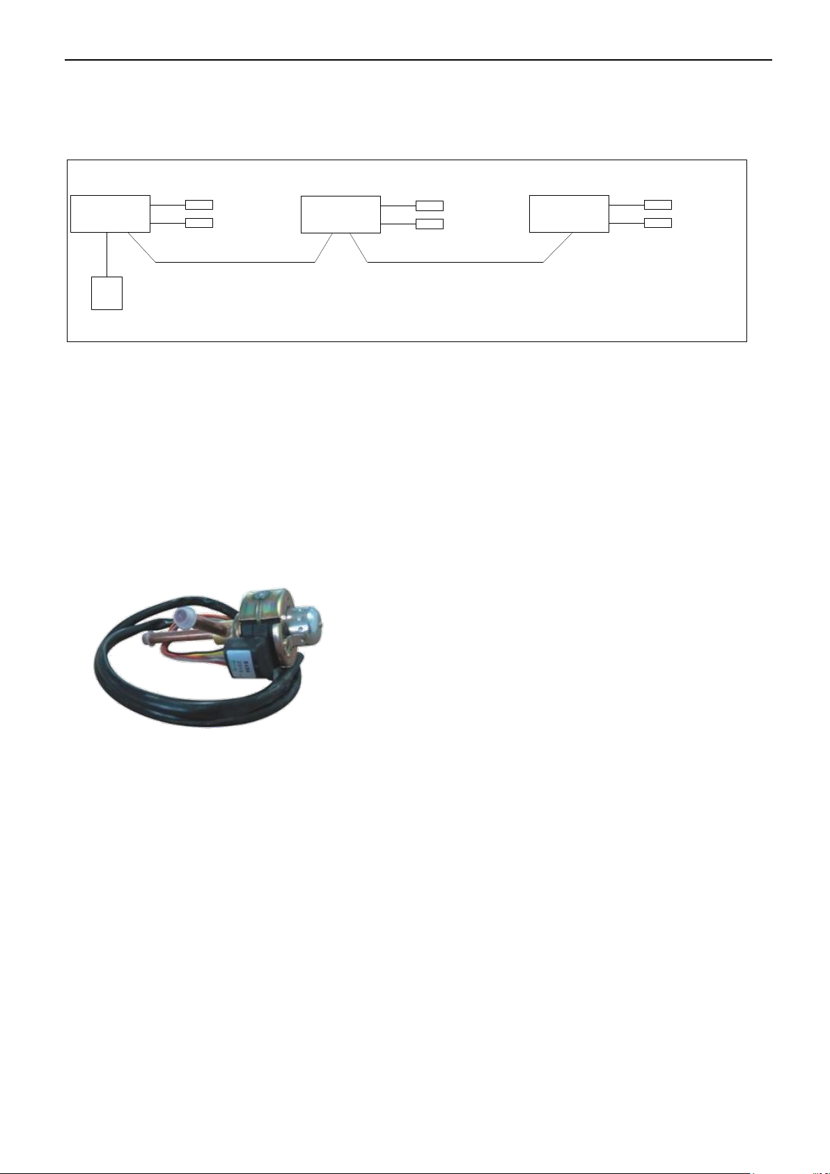
Wired controller
Three-core shielding
twisted pair
Three-core shielding
twisted pair
Water outlet temp.
Water outlet temp.
Water outlet temp.
Total water outlet temp.
(Just for master unit)
Total water outlet temp.
(Just for master unit)
Total water outlet temp.
(Just for master unit)
Easily connect between main unit and slave units.
All the units can be connected together with a wired controller in series type. Using three-core shielded
twisted wire as communication wire.
5).Environmental care
R410a— the environmental refrigerant.
Chlorine-free and environmental friendly refrigerant, zero ozone depletion potential.
High density refrigerant, therefore, less refrigerant required.
Leak-tight refrigerant circuit, Brazed refrigerant connections for increased leak-tightness.
6). Economical operation
New design adopts electronic expansion valve precise refrigerant control in wider range. Electronic
expansion valve allows operation at lower condensing pressure, the adjustment can be made fast linear
response, making the system more stable output, the indoor temp. more uniform, and enhanced human
comfortable.
7). Compact structure
The structure of air-cooled modular chiller is compact, light weight. The system adopts double-pipe or shell
and tube heat exchanger, which not only greatly enhanced the transfer performance, but also reduced the
unit weight, the lightest single module has only 380kg.
8). Back up function
6
When unit is failure
If master unit fails, all the units will stop.
If one slave unit fails, this unit will stop but the others will keep running.
When the master unit fails, any of the slave one can be set as the master unit by manual setting.
When unit is under protection
If master unit’s protection occurs, this unit will stop but the others will keep running.
If slave unit’s protection occurs, this unit will stop but the others will keep running.
( Except PE, P9 protection happen)

MCAC-ATSM-2014-09 Aqua tempo power series tropical air-cooled scroll chiller 50Hz
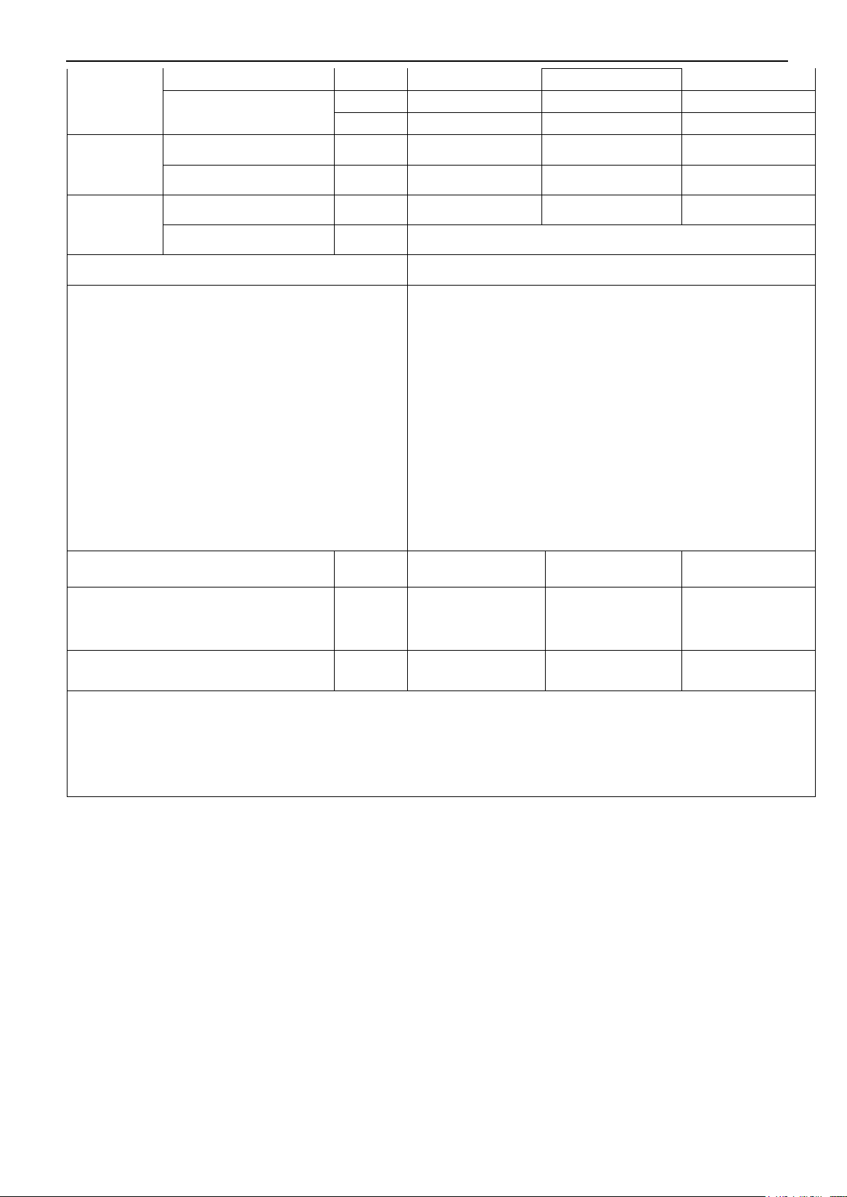
Master Slave
Master Slave
Mode
Ambient temp. range
Water outlet temp. range
Cooling
10˚C ~52˚C
5˚C ~17˚C (7˚C is default)
10˚C ~46˚C
0~17˚C(0˚C must add antifreeze)
Heating
-10˚C ~21˚C
45˚C ~50˚C (45˚C is default)
22˚C ~50˚C
9).Strong micro-computer intelligent control and monitor function.
Optimizing the design of system and using varieties of protection devices, to make the system more safe and
reliable.
10). Superior reliability
System will be more reliable with new type efficient heat exchanger.
Evaporator of 25KW and 30KW module adopt double pipe heat exchanger,evaporator of 60kW ,120kW and
180kW modules adopt shell and tube heat exchanger.
Double pipe heat exchanger Shell and tube heat exchanger
11) Applicable temp. range
7

Aqua tempo power series tropical air-cooled scroll chiller 50Hz MCAC-ATSM-2014-09
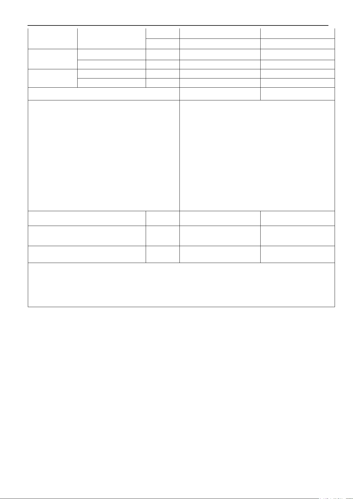
Model
Mode
Compressor
quantity
Refrigerant
Refrigeration
system
Electrical
controller no.
Maximum
combinations
Digital
Constant
MGBT-D25W/RN1
Cooling & Heating
1 1 R410A 2 1
16
MGBT-F25W/RN1
Cooling & Heating
0 2 R410A 2 1
16
MGBT-D30W/RN1
Cooling & Heating
1 1 R410A 2 1
16
MGBT-F30W/RN1
Cooling & Heating
0 2 R410A 2 1
16
MGBT-F60W/RN1
Cooling & Heating
0 2 R410A 2 1
16
MGBT-D60W/RN1
Cooling & Heating
1 2 R410A 3 1
16
MGBT-F120W/RN1
Cooling & Heating
0 4 R410A 4 2
8
MGBT-F180W/RN1
Cooling & Heating
0 6 R410A 6 3
5
MGBT-F250W/RN1
Cooling & Heating
0 8 R410A 4 2
8
-15˚C
Ambient temp. range
-10˚C
-5˚C
0˚C
5˚C
10˚C
15˚C
20˚C
25˚C
30˚C
35˚C
40˚C
45˚C
50˚C
Cooling range
10˚C
52˚C
Heating range
-10˚C
21˚C
Water outlet temp. range
5˚C
17˚C
50˚C
5˚C
17˚C
Heating range
Cooling range
45˚C
22˚C
0˚C
45˚C
50˚C
Cooling range
0˚C
17˚C
Heating range
22˚C
50˚C
Chilled outlet water temp. can be adjusted by wired controller according to customer’s requirement.
1.5 Capacity lineup
8

MCAC-ATSM-2014-09 Aqua tempo power series tropical air-cooled scroll chiller 50Hz
Model
MGBT-F25W/RN1
MGBT-D25W/RN1
Cooling Capacity (*1)
kW
28
Btu/h
95,500
Cooling Capacity (*2)
kW
24.9
Btu/h
85,000
Heating Capacity
kW
29.5
EER(*1)
kW/ kW
3.01
EER(*2)
kW/ kW
2.20
COP
kW/ kW
3.21
Power supply
V/Ph/Hz
380~415/3/50
Power supply
Manual switch
A
50
Fuse
A
36
Compressor
Type
Scroll (fixed speed)
Digital Scroll + Fixed speed
Brand
Copeland
Copeland
Model
ZP61KCE-TFD-522
ZPD61KCE-TFD-532/
ZP61KCE-TFD-522
Quantity
Pieces
2
1+1
Power input
Cooling (*1)
kW
9.3
Cooling rated current (*1) A 14.6
Cooling (*2)
kW
11.16
Cooling rated current (*2) A 17.52
Heating
kW
9.2
Heating rated current
A
14.3
Max. Input consumption
kW
12.6
12.5
Rated Current
A
19
19
Refrigerant
Type
R410A
Refrigerant control
EXV
Weight
kg
3.1×2
Condenser
(Air side)
Air side heat-exchanger type
Fin-coil
Quantity of fan motor
Pieces
1
Air flow volume
×103m3/h
12
Fan motor model
YDK400-8-YA
Fan motor rated current
A
2.95
Fan motor input
kW
0.65
Evaporator
(Water side)
Water side heat-exchanger type
Double-pipe
Water pressure drop
kPa
60
Volume
L
10
Water inlet/outlet pipeline
inside normal diameter
inch
1-1/2”
Water flow volume
m3/h
4.8
Max. Pressure
MPa
1
Evaporator volume
L
10
Water pipe connection type
Flexible joint
Dimension
Net(W×H×D)
mm
1514×1865×841
1.6 Specification: MGBT-F25W/RN1, MGBT-D25W/RN1
9
Aqua tempo power series tropical air-cooled scroll chiller 50Hz MCAC-ATSM-2014-09
inch
59.6×73.4×33.1
Packing size(W×H×D)
mm
1590×2065×995
inch
62.6×81.3×39.2
Weight
Net weight
kg
380
Gross weight
kg
400
Connection wire
Power wire
mm2×No.
10×4+6×1
Signal wire
mm2×No.
0.75×3-core with shielding
Control type
Wired controller
Safety protection device
1) Protection for over-high discharge pressure.
2) Protection for over-low suction pressure.
3) Power supply phase sequence protection.
4) Anti-freezing protection in cooling mode.
5) Anti-freezing protection in Winter.
6) Protection for compressor over current.
7) Protection for compressor overload.
8) Outlet and inlet water temp. difference protection.
9) Compressor discharge temp. protection.
10) Water flow cut-off protection.
11) Sensor malfunction protection.
12) Low-temperature protection of shell and tube heat
exchanger.
Sound level(semi-anechoic )
dB(A)
65
Operation water temp.
℃
Cooling:5~17 Heating:45~50
Ambient temp.
℃
Cooling:10~52 Heating:-10~21
Note: Specifications are based on the following conditions:
Cooling : (*1) chilled water inlet/outlet: 12˚C / 7˚C, and outdoor ambient temp. of 35°C (117℉) DB.
(*2) chilled water inlet/outlet: 12˚C / 7˚C, and outdoor ambient temp. of 46˚C(140℉) DB.
Heating : warm water inlet/outlet: 40˚C / 45˚C, and outdoor ambient temp. 7˚C DB/6°CWB.
Water side fouling factor: 0.086m2˚C /kW.
10

MCAC-ATSM-2014-09 Aqua tempo power series tropical air-cooled scroll chiller 50Hz
Model
MGBT-F30W/RN1
MGBT-D30W/RN1
Cooling Capacity (*1)
kW
30
Btu/h
102,300
Cooling Capacity (*2)
kW
25.8
Btu/h
88,030
Heating Capacity
kW
32
EER(*1)
kW/ kW
3.00
EER(*2)
kW/ kW
2.15
COP
kW/ kW
3.27
Power supply
V/Ph/Hz
380~415/3/50
Power supply
Manual switch
A
50
Fuse
A
36
Compressor
Type
Scroll (fixed speed)
Digital Scroll + Fixed speed
Brand
Copeland
Copeland
Model
ZP61KCE-TFD-522
ZPD61KCE-TFD-532/
ZP61KCE-TFD-522
Quantity
Pieces
1+1
1+1
Power input
Cooling (*1)
kW
10.0
Cooling rated current (*1)
A
16.3
Cooling (*2)
kW
12
Cooling rated current (*2) A 19.56
Heating
kW
9.8
Heating rated current
A
16.0
Max. Input consumption
kW
12.6
12.5
Rated Current
A
21.1
21.1
Refrigerant
Type
R410A
Refrigerant control
EXV
Weight
kg
3.1×2
Condenser
(Air side)
Air side heat-exchanger type
Fin-coil
Quantity of fan motor
Pieces
1
Air flow volume
×103m3/h
12
Fan motor model
YDK400-8-YA
Fan motor rated current
A
2.95
Fan motor input
kW
0.65
Evaporator
(Water side)
Water side heat-exchanger type
Double-pipe
Water pressure drop
kPa
60
Volume
L
10
Water inlet/outlet pipeline
inside normal diameter
mm
DN40
inch
1-1/2”
Water flow volume
m3/h
5.2
Max. Pressure
MPa
1
Evaporator volume
L
10
Water pipe connection type
Flexible joint
Dimension
Net(W×H×D)
mm
1514×1865×841
inch
59.6×73.4×33.1
1.7 Specification: MGBT-F30W/RN1, MGBT-D30W/RN1
11
Aqua tempo power series tropical air-cooled scroll chiller 50Hz MCAC-ATSM-2014-09
Packing (W×H×D)
mm
1590×2065×995
inch
62.6×81.3×39.2
Weight
Net weight
kg
380
Gross weight
kg
415
Connection wire
Power wire
mm2×No.
10×4+6×1
Signal wire
mm2×No.
0.75×3-core with shielding
Control type
Wired controller
Safety protection device
1) Protection for over-high discharge pressure.
2) Protection for over-low suction pressure.
3) Power supply phase sequence protection.
4) Anti-frozen protection in cooling mode.
5) Anti-frozen protection in Winter.
6) Protection for compressor over current.
7) Protection for compressor overload.
8) Outlet and inlet water temp. difference protection.
9) Compressor discharge temp. protection.
10) Water flow cut-off protection.
11) Sensor malfunction protection.
12) Low-temperature protection of shell and tube heat
exchanger.
Sound level(semi-anechoic )
dB(A)
65
Operation water temp.
℃
Cooling:5~17 Heating:45~50
Ambient temp.
℃
Cooling:10~52 Heating:-10~21
Note: Specifications are based on the following conditions:
Cooling : (*1) chilled water inlet/outlet: 12˚C / 7˚C, and outdoor ambient temp. of 35°C (117℉) DB.
(*2) chilled water inlet/outlet: 12˚C / 7˚C, and outdoor ambient temp. of 46˚C (140℉)DB
Heating : warm water inlet/outlet: 40˚C / 45˚C, and outdoor ambient temp. 7˚C DB/6°CWB.
Water side fouling factor: 0.086m2˚C /kW.
12

MCAC-ATSM-2014-09 Aqua tempo power series tropical air-cooled scroll chiller 50Hz
Model
MGBT-F60W/RN1
MGBT-D60W/RN1
MGBT-F120W/RN1
Cooling Capacity (*1)
kW
60
120
Btu/h
204,700
409,400
Cooling Capacity (*2)
kW
51.6
103.2
Btu/h
176,100
352,100
Heating Capacity
kW
64
65
128
EER(*1)
kW/ kW
3.11
3.09
3.12
EER(*2)
kW/ kW
2.20
2.22
2.23
COP
kW/ kW
3.23
3.19
3.08
Power supply
V/Ph/Hz
380~415/3/50
Power supply
Manual switch
A
100
200
Fuse
A
70
150
Compressor
Type
Scroll (fixed speed)
Digital Scroll + Fixed
speed
Scroll (fixed speed)
Brand
Copeland
Copeland
Copeland
Model
ZP137KCE-TFD-522
ZP137KCE-TFD-522
/ZPD72KCE-TFD-433
/ ZP67KCE-TFD-420
ZP137KCE-TFD-522
Quantity
Pieces 2 1+1+1
4
Power input
Cooling (*1)
kW
19.3
19.4
38.5
Cooling rated current (*1)
A
33.6
33.6
68.8
Cooling (*2)
kW
23.16
23.28
46.2
Cooling rated current (*2)
A
40.32
40.32
82.56
Heating
kW
19.8
20.4
41.5
Heating rated current
A
34.3
35.1
71.8
Max. Input consumption
kW
29.5
29
55.5
Rated Current
A
51.5
51.5
130
Refrigerant
Type
R410A
R410A
R410A
Refrigerant control
EXV+ capillary
Weight
kg
6.0×2
6.5×2
6.0×4
Condenser
(Air side)
Air side heat-exchanger type
Fin-coil
Quantity of fan motor
Pieces 2 2
4
Air flow volume
×103m3/h
24
24
48
Fan motor model
YS700-6F
YDK550-6E
YS700-6F
Fan motor rated current
A
1.8×2
4.0×2
1.8×4
Fan motor input
kW
0.9×2
0.865×2
0.9×4
Evaporator
(Water side)
Water side heat-exchanger type
Shell and tube
Shell and tube
Shell and tube
Water pressure drop
kPa
15
15
25
Volume L 42
42
64
Water inlet/outlet pipeline
inside normal diameter
mm
DN100
DN100
DN65
inch
4”
4”
2-1/2”
Water flow volume
m3/h
10.3
10.3
22.4
Max. Pressure
MPa 1 1
1
Evaporator volume
L
42
42
46
Water pipe connection type
Flexible joint
Flexible joint
Flexible joint
Dimension
Net(W×H×D)
mm
2000×1880×900
2000×1880×900
2000×1685×2090
1.8 Specification: MGBT-F60W/RN1, MGBT-D60W/RN1, MGBT-F120W/RN1
13
Aqua tempo power series tropical air-cooled scroll chiller 50Hz MCAC-ATSM-2014-09
inch
78.7×74×35.4
78.7×74×35.4
78.7×66.3×82.3
Packing (W×H×D)
mm
2090×2095×985
2090×2095×985
2090×1755×2240
inch
82.3×82.5×38.8
82.3×82.5×38.8
82.3×69×88.2
Weight
Net weight
kg
580
600
1150
Gross weight
kg
650
640
1200
Connection
wire
Power wire
mm2×No.
25×4+16 ×1
16×4+10×1
35×3+16 ×2
Signal wire
mm2×No.
0.75×3-core with shielding
Control type
Wired controller
Safety protection device
1) Protection for over-high discharge pressure.
2) Protection for over-low suction pressure.
3) Power supply phase sequence protection.
4) Anti-frozen protection in cooling mode.
5) Anti-frozen protection in Winter.
6) Protection for compressor over current.
7) Protection for compressor overload.
8) Outlet and inlet water temp. difference protection.
9) Compressor discharge temp. protection.
10) Water flow cut-off protection.
11) Sensor malfunction protection.
12) Low-temperature protection of shell and tube heat exchanger.
Sound level(semi-anechoic )
dB(A)
65
67
70
Operation water temp.
℃
Cooling:5~17
Heating:45~50
Cooling:0~17(5℃
must add antifreeze)
Heating:22~50
Cooling:5~17
Heating:45~50
Ambient temp.
℃
Cooling:10~52
Heating:-10~21
Cooling:10~52
Heating:-10~21
Cooling:10~52
Heating:-10~21
Note: Specifications are based on the following conditions:
Cooling : (*1) chilled water inlet/outlet: 12˚C / 7˚C, and outdoor ambient temp. of 35°C (117℉) DB.
(*2) chilled water inlet/outlet: 12˚C / 7˚C, and outdoor ambient temp. of 46˚C (140℉)DB
Heating : warm water inlet/outlet: 40˚C / 45˚C, and outdoor ambient temp. 7˚C DB/6°CWB.
Water side fouling factor: 0.086m2˚C /kW.
14

MCAC-ATSM-2014-09 Aqua tempo power series tropical air-cooled scroll chiller 50Hz
Model
MGBT-F180W/RN1
MGBT-F250W/RN1
Cooling Capacity (*1)
kW
180
250
Btu/h
614,100
830000
Cooling Capacity (*2)
kW
155.8
216
Btu/h
528,200
737000
Heating Capacity
kW
195
270
EER(*1)
kW/ kW
3.11
3.19
EER(*2)
kW/ kW
2.66
2.50
COP
kW/ kW
3.28
3.38
Power supply
V/Ph/Hz
380~415/3/50
380~415/3/50
Power supply
Manual switch A 300
450
Fuse
A
200
300
Compressor
Type
Scroll (fixed speed)
Scroll (fixed speed)
Brand
Copeland
Copeland
Model
ZP137KCE-TFD-522
SH120A4ALC
Quantity
Pieces 6 8
Power input
Cooling (*1)
kW
57.9
78.3
Cooling rated current (*1)
A
100.8
141.9
Cooling (*2)
kW
58.5
86.3
Cooling rated current (*2)
A
121
170.3
Heating
kW
59.4
80
Heating rated current
A
102.9
146
Max. Input consumption
kW
78.3
104.9
Rated Current A 155.1
200
Refrigerant
Type
R410A
R410A
Refrigerant control
EXV+ capillary
EXV+ capillary
Weight
kg
6.0×6
15×4
Condenser (Air
side)
Air side heat-exchanger type
Fin-coil
Fin-coil
Quantity of fan motor
Pieces 6 8
Air flow volume
×103m3/h
72
96
Fan motor model
YS700-6F/ YS700-6F-1
YS700-6F-1/YS700-6F-2
Fan motor rated current
A
1.8×6
1.8×8
Fan motor input
kW
0.9×6
0.9×8
Evaporator
(Water side)
Water side heat-exchanger type
Shell and tube
Shell and tube
Water pressure drop
kPa
30
40
Volume
L
90
131
Water inlet/outlet pipeline
inside normal diameter
mm
DN80
DN100
inch
3”
4”
Water flow volume
m3/h
31
43
Max. Pressure
MPa 1 1
Evaporator volume L 90
131
Water pipe connection type
Flexible joint
Flexible joint
Dimension
Net(W×H×D)
mm
2850×2000×2110
3800×2130×2000
inch
112.2×78.7×83.1
149.6×83.86×78.74
1.9 Specification: MGBT-F180W/RN1, MGBT-F250W/RN1
15
Aqua tempo power series tropical air-cooled scroll chiller 50Hz MCAC-ATSM-2014-09
Packing size(W×H×D)
mm
2980×2135×2260
3900×2200×2100
inch
117.3×84.1×89
153.54×86.61×82.68
Weight
Net weight
kg
1730
2450
Gross weight
kg
1780
2500
Connection wire
Power wire
mm2×No.
70×3+35×2
185×4+70×1
Signal wire
mm2×No.
0.75×3-core with shielding
0.75×3-core with shielding
Control type
Wired controller
Wired controller Wired controller
Safety protection device
1) Protection for over-high discharge pressure.
2) Protection for over-low suction pressure.
3) Power supply phase sequence protection.
4) Anti-frozen protection in cooling mode.
5) Anti-frozen protection in Winter.
6) Protection for compressor over current.
7) Protection for compressor overload.
8) Outlet and inlet water temp. difference protection.
9) Compressor discharge temp. protection.
10) Water flow cut-off protection.
11) Sensor malfunction protection.
12)Low-temp. protection of shell-and-tube heat exchanger.
Sound level(semi-anechoic )
dB(A)
74
74
Operation water temp.
℃
Cooling:5~17
Heating:45~50
Cooling:0~17(5℃ must
add antifreeze)
Heating:22~50
Ambient temp.
℃
Cooling:10~52
Heating:-10~21
Cooling:10~52
Heating:-10~21
Note: Specifications are based on the following conditions:
Cooling : (*1) chilled water inlet/outlet: 12˚C / 7˚C, and outdoor ambient temp. of 35°C (117℉) DB.
(*2) chilled water inlet/outlet: 12˚C / 7˚C, and outdoor ambient temp. of 46˚C (140℉)DB
Heating : warm water inlet/outlet: 40˚C / 45˚C, and outdoor ambient temp. 7˚C DB/6°CWB.
Water side fouling factor: 0.086m2˚C /kW.
16

MCAC-ATSM-2014-09 Aqua tempo power series tropical air-cooled scroll chiller 50Hz
Model
Outdoor Unit
Application
Power
Supply
Compressor
OFM
Hz
VOL
Ph
Min.
Max.
TOCA
MFA
LRA
RLA
Qty
KW
FLA
Qty
MGBT-F25W/RN1
50
380-415
3
342
456
25
36
64
10.9
2
0.65
2.95
1
MGBT-D25W/RN1
50
380-415
3
342
456
25
36
64/64
10.9/10.9
2
0.65
2.95
1
MGBT-F30W/RN1
50
380-415
3
342
456
25
36
64
10.9
2
0.65
2.95
1
MGBT-D30W/RN1
50
380-415
3
342
456
25
36
64/64
10.9/10.9
2
0.65
2.95
1
MGBT-F60W/RN1
50
380-415
3
342
456
52
100
118
20.7
2
0.9x2
1.8x2
2
MGBT-D60W/RN1
50
380-415
3
342
456
52
100
118/82.4/74
20.7/12.7/11.8
3
0.865x2
4.0x2
2
MGBT-F120W/RN1
50
380-415
3
342
456
90
200
118
20.7
4
0.9x4
1.8x4
4
MGBT-F180W/RN1
50
380-415
3
342
456
135
300
118
20.7
6
0.9x6
1.8x6
6
MGBT-F250W/RN1
50
380-415
3
342
456
191
300
142
20.7
8
0.9x8
1.8x8
8
Voltage imbalance between phases to be <2%.
1.10 Electric Characteristics
Remark:
TOCA: Total Over-current Amps. (A)
MFA: Max. Fuse Amps. (A)
LRA: Locked Rotor Amps. (A)
RLA: Rated Load Amps. (A)
OFM: Outdoor Fan Motor.
FLA: Full Load Amps. (A)
KW: Rated Motor Input (KW)
17
Aqua tempo power series tropical air-cooled scroll chiller 50Hz MCAC-ATSM-2014-09
Model
Unit
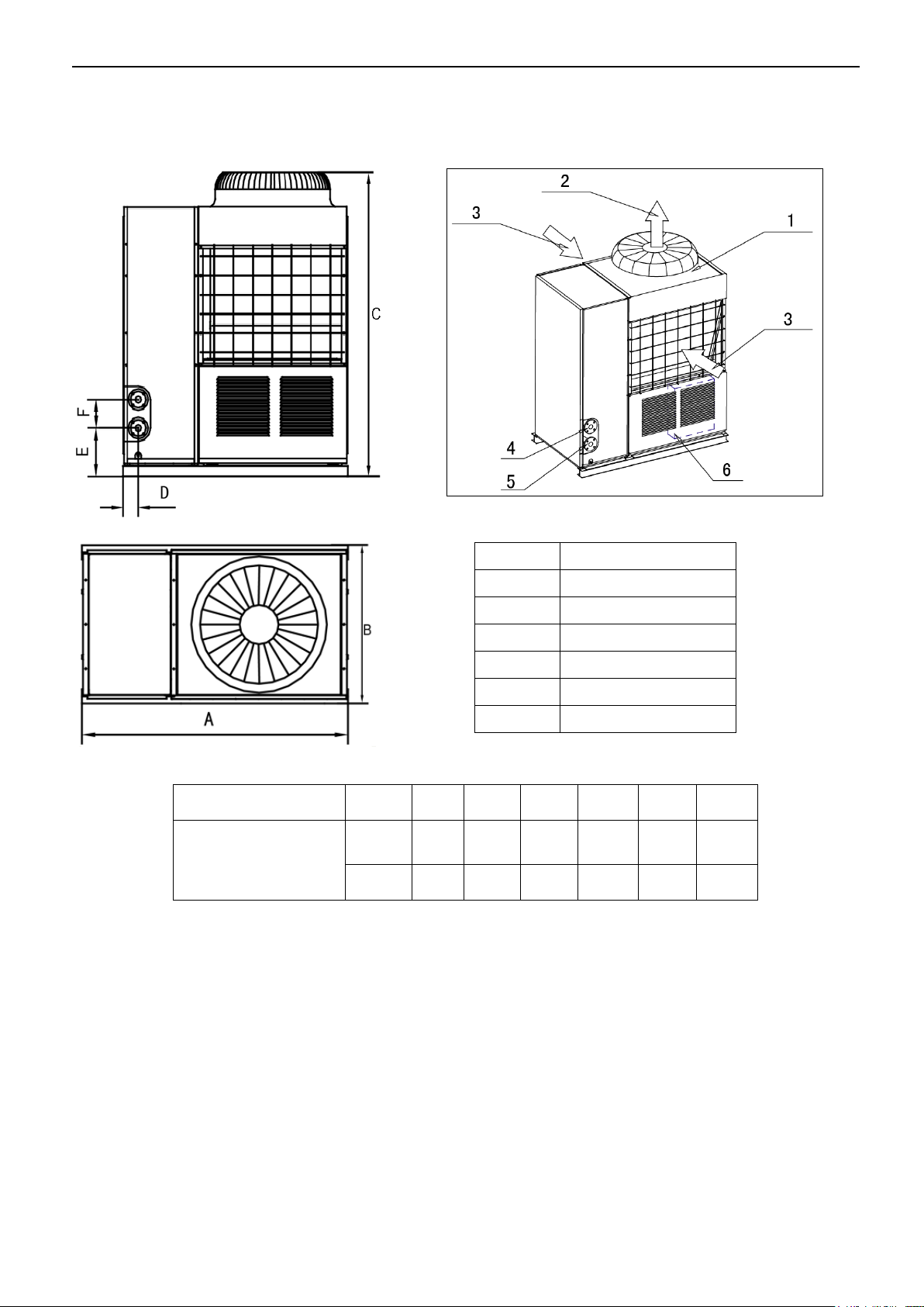
A B C D E
F
MGBT-F(D)25W/RN1
MGBT-F(D)30W/RN1
mm
1514
841
1865
115
315
172
inch
59.6
33.11
73.43
4.53
12.4
6.77
No.
Name
1
Top cover
2
Air outlet
3
Air inlet
4
Water outlet
5
Water inlet
6
Electric control box
1.11 Outlook drawing: MGBT-F25W/RN1, MGBT-D25W/RN1, MGBT-D30W/RN1, MGBT-F30W/RN1
Front view
Top view
18
MCAC-ATSM-2014-09 Aqua tempo power series tropical air-cooled scroll chiller 50Hz
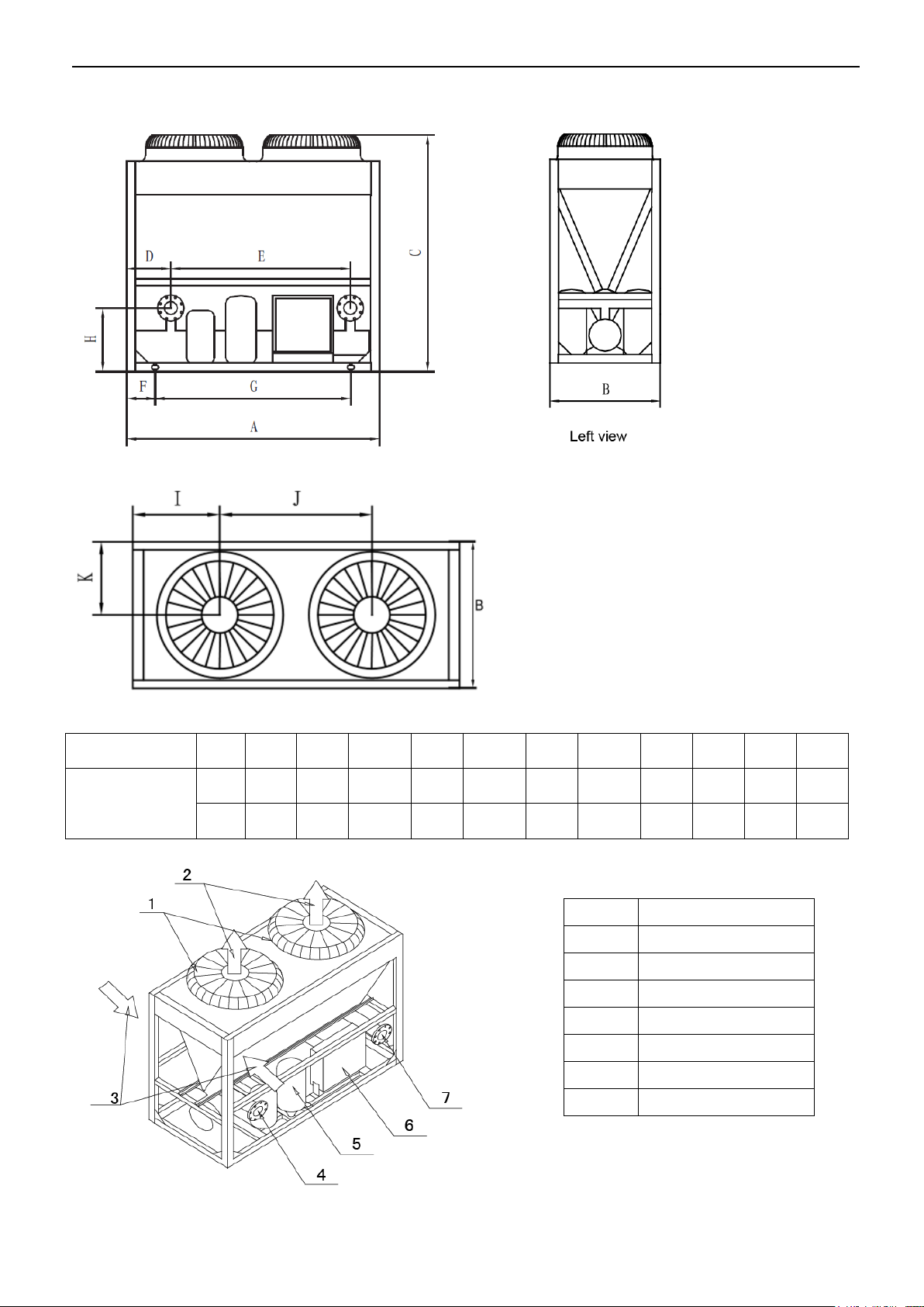
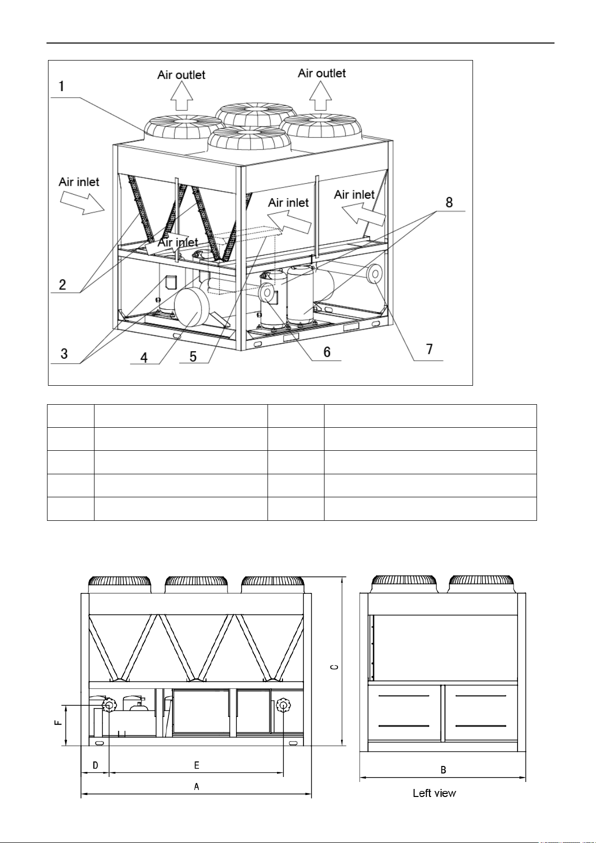
Model
Unit
A B C D E F G H I J K
MGBT-F60W/RN1
mm
2000
900
1880
350
1420
225
1500
506
530
930
450
inch
78.74
35.4
74
13.78
55.91
8.86
59.06
19.92
20.87
36.61
17.72
No.
Name
1
Top cover
2
Air outlet
3
Air inlet
4
Water outlet
5
Compressor
6
Electric control box
7
Water inlet
1.12 Outlook drawing: MGBT-F60W/RN1
Front view
Top view
19
Aqua tempo power series tropical air-cooled scroll chiller 50Hz MCAC-ATSM-2014-09
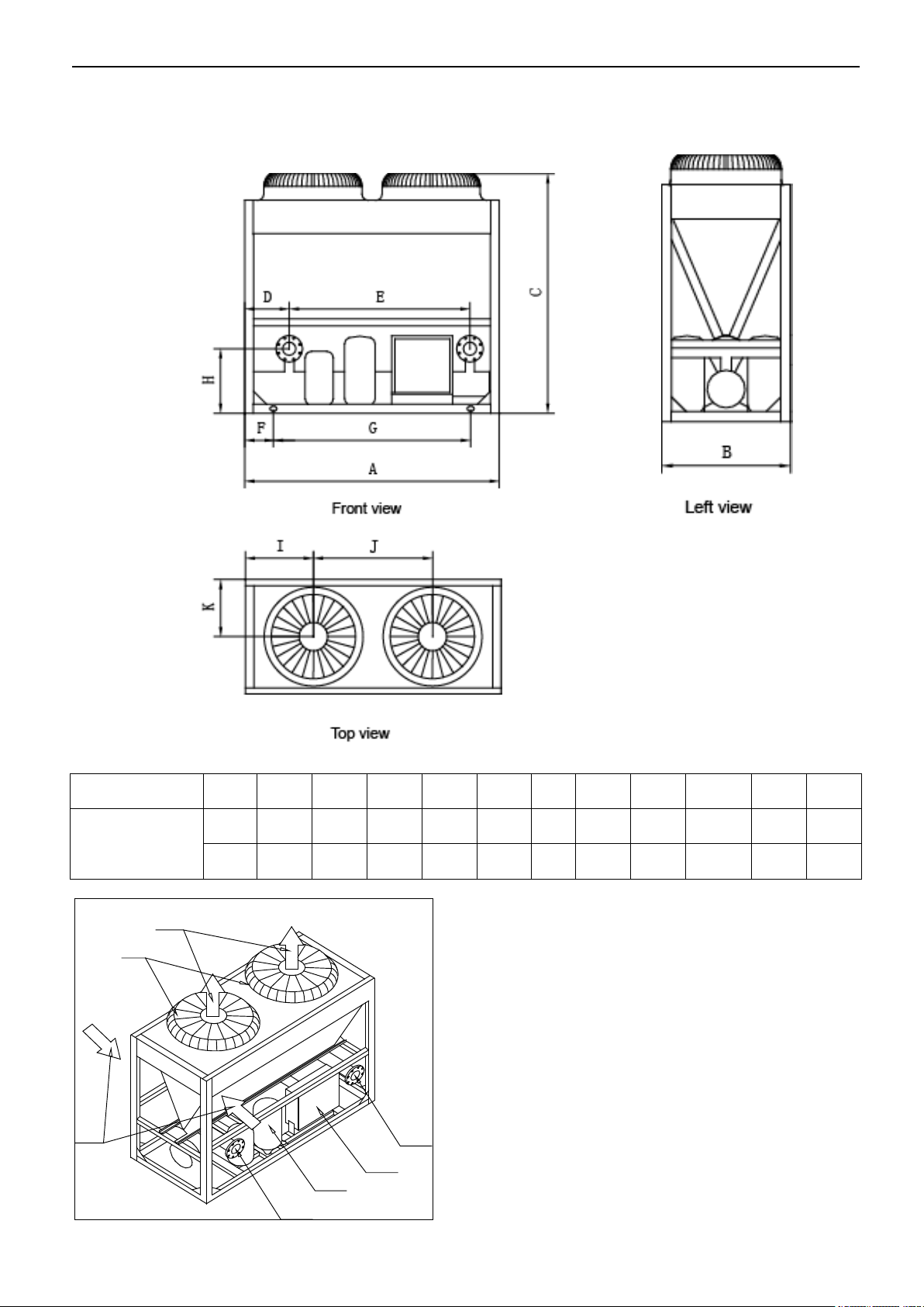
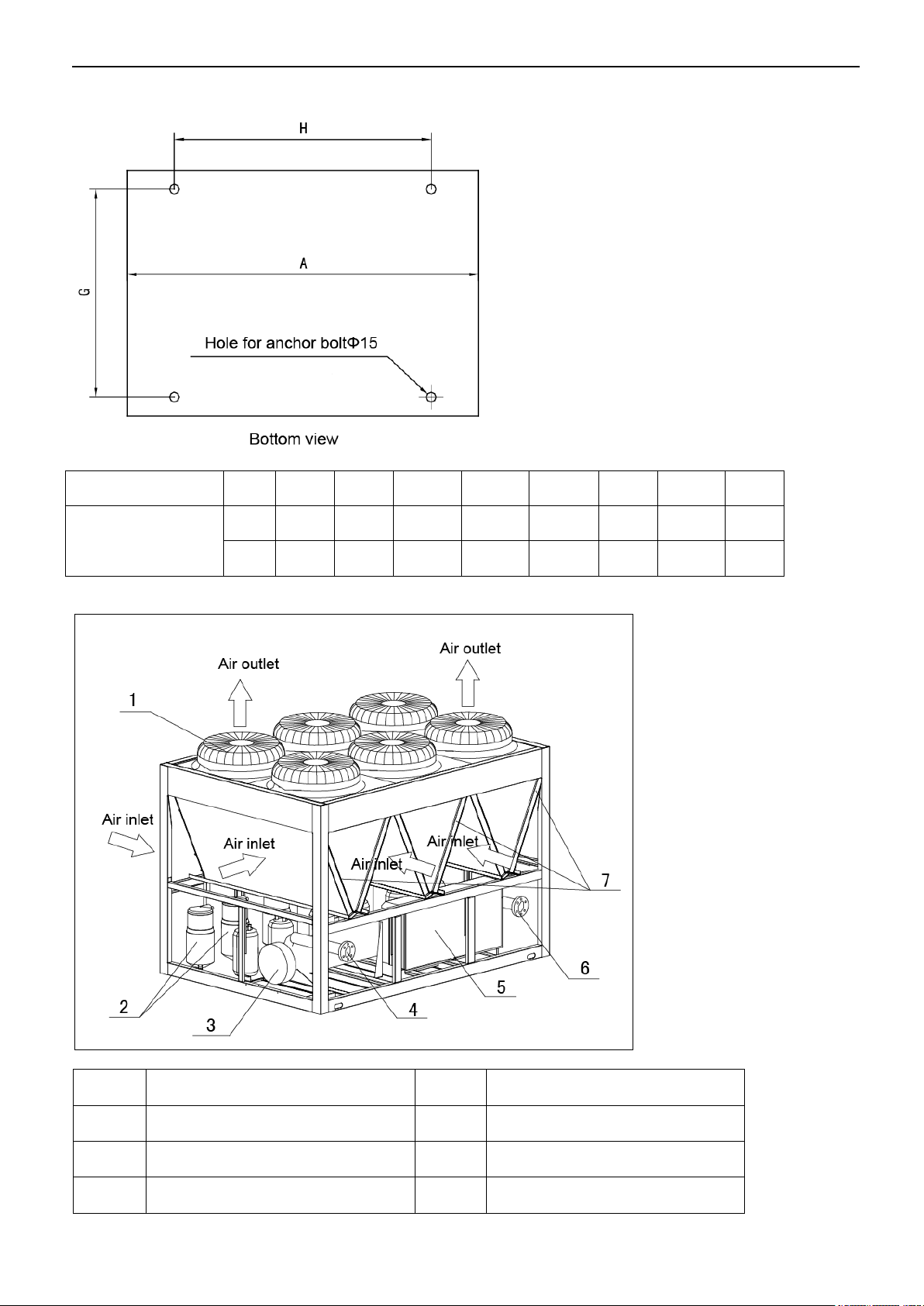
Model
unit A B C D E F G H I J
K
MGBT-D60W/RN1
mm
2000
900
1880
350
1420
225
1500
506
530
930
450
inch
78.74
35.43
74
13.78
55.9
8.86
59.05
19.92
28.87
36.61
17.72
3
1
2
4
5
6
7
1.13 Outlook drawing: MGBT-D60W/RN1
20
MCAC-ATSM-2014-09 Aqua tempo power series tropical air-cooled scroll chiller 50Hz
No.
Name
No.
Name
1
Top cover
5
Compressor
2
Air outlet
6
Electric control box
3
Air inlet
7
Water inlet
4
Water outlet
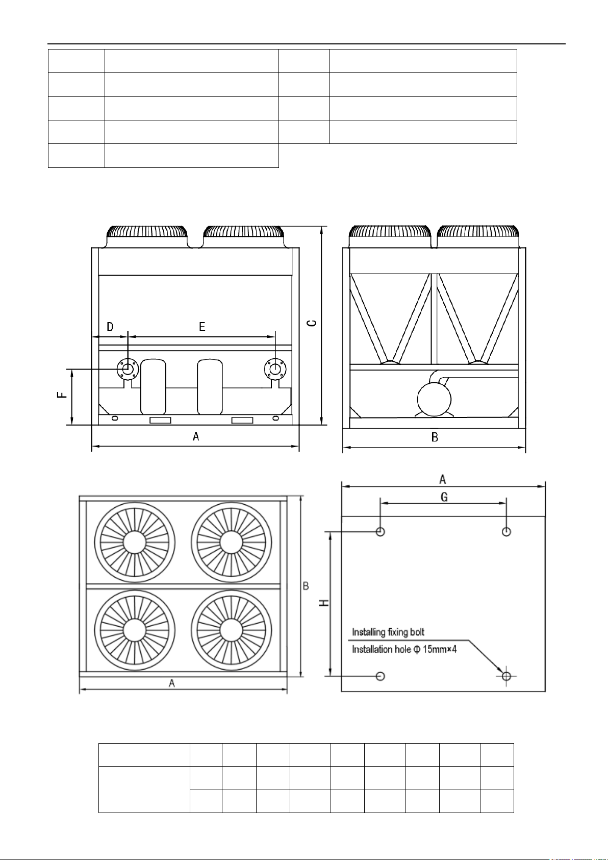
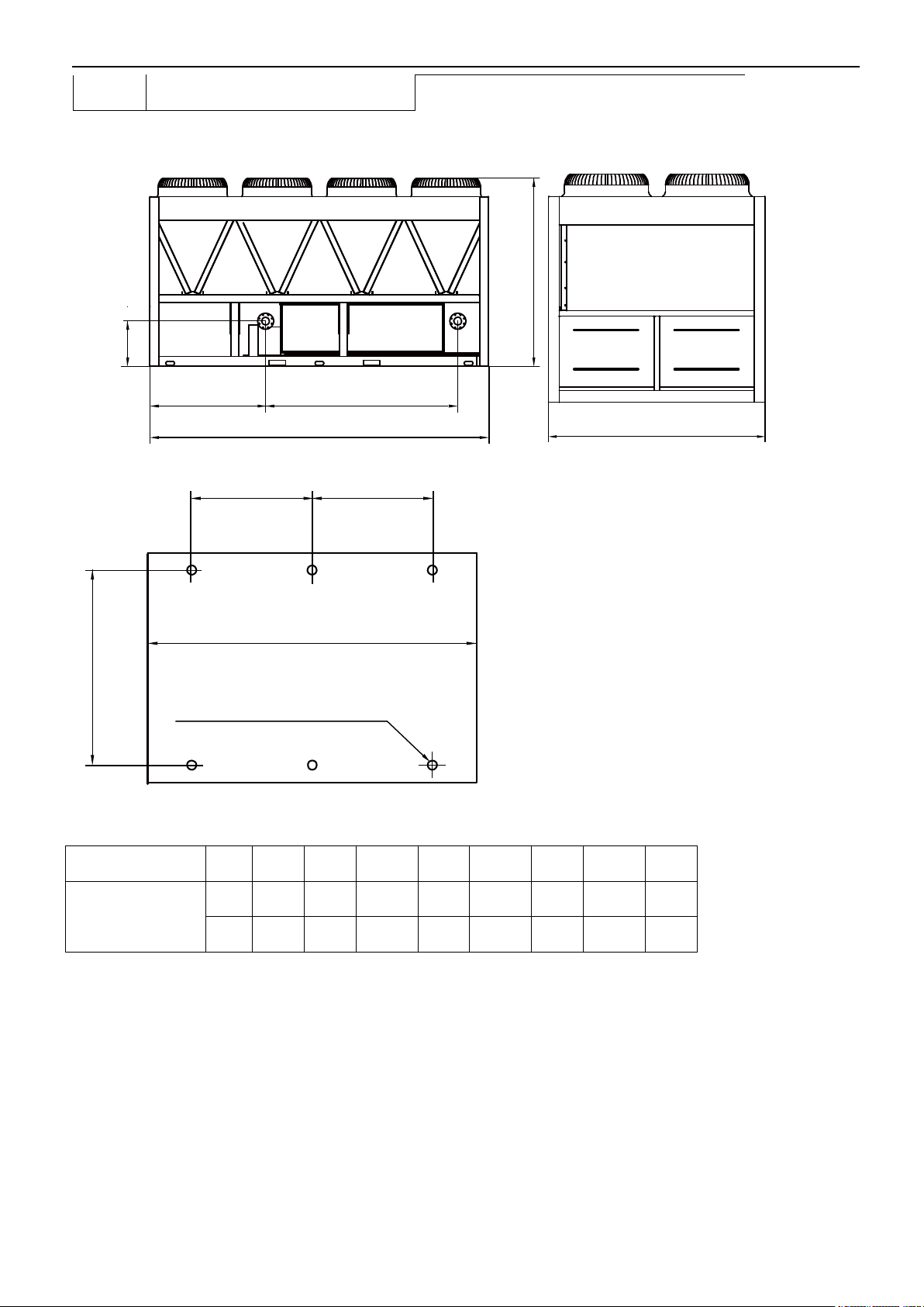
Model
Unit
A B C D E F G
H
MGBT-F120W/RN1
mm
2000
1685
2080
350
1420
506
1550
1586
inch
78.74
66.34
81.89
13.78
55.91
19.92
61.02
62.44
1.14 Outlook drawing: MGBT-F120W/RN1
Front view Side view
Top view Anchor hole
:
21
Aqua tempo power series tropical air-cooled scroll chiller 50Hz MCAC-ATSM-2014-09
No.
Name
No.
Name
1
Top cover
5
Electric control box Air inlet
2
Condenser
6
Water outlet
3
Compressor
7
Water inlet
4
Evaporator
8
Compressor
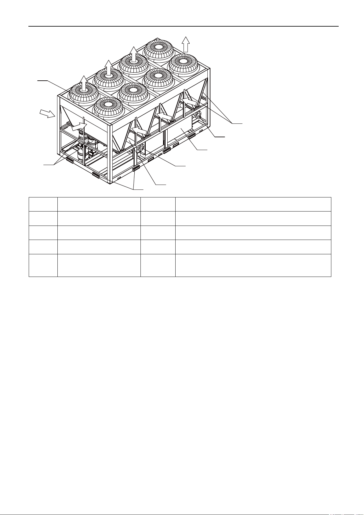
1.15 Outlook drawing: MGBT-F180W/RN1
22
MCAC-ATSM-2014-09 Aqua tempo power series tropical air-cooled scroll chiller 50Hz
Model
unit A B C D E F G H
MGBT-F180W/RN1
Mm
2850
2000
2110
3470
2156
506
1888
2388
inch
112.2
78.74
83.07
136.61
84.88
19.92
74.33
94.02
No.
Name
No.
Name
1
Top cover
5
Electric control box
2
Compressor
6
Water inlet
3
Evaporator
7
Condenser
Front view
23
Aqua tempo power series tropical air-cooled scroll chiller 50Hz MCAC-ATSM-2014-09
4
Water outlet
Front view
E
A
C
F
D
Left view
B
Bottom view
H H
G
A
Hole for anchor boltΦ15
Model
unit A B C D E F G H
MGBT-F250W/RN1
Mm
3800
2000
2130
1235
2156
573
1888
1551
inch
149.6
78.74
83.86
48.62
84.88
22.56
74.33
61.06
1.16 Outlook drawing: MGBT-F250W/RN1
24
MCAC-ATSM-2014-09 Aqua tempo power series tropical air-cooled scroll chiller 50Hz
1
Air outlet
Air outlet
Air outlet
Air outlet
Air inlet
2
8
4
5
6
7
3
A
i
r
i
n
l
e
t
A
i
r
i
n
l
e
t
A
i
r
i
n
l
e
t
A
i
r
i
n
l
e
t
No.
Name
No.
Name
1
Top cover
5
Electric control box
2
Compressor
6
Water inlet
3
Evaporator
7
Condenser
4
Water outlet
8
Transportation guard plate (Be removed off
after installation)
25
Aqua tempo power series tropical air-cooled scroll chiller 50Hz MCAC-ATSM-2014-09
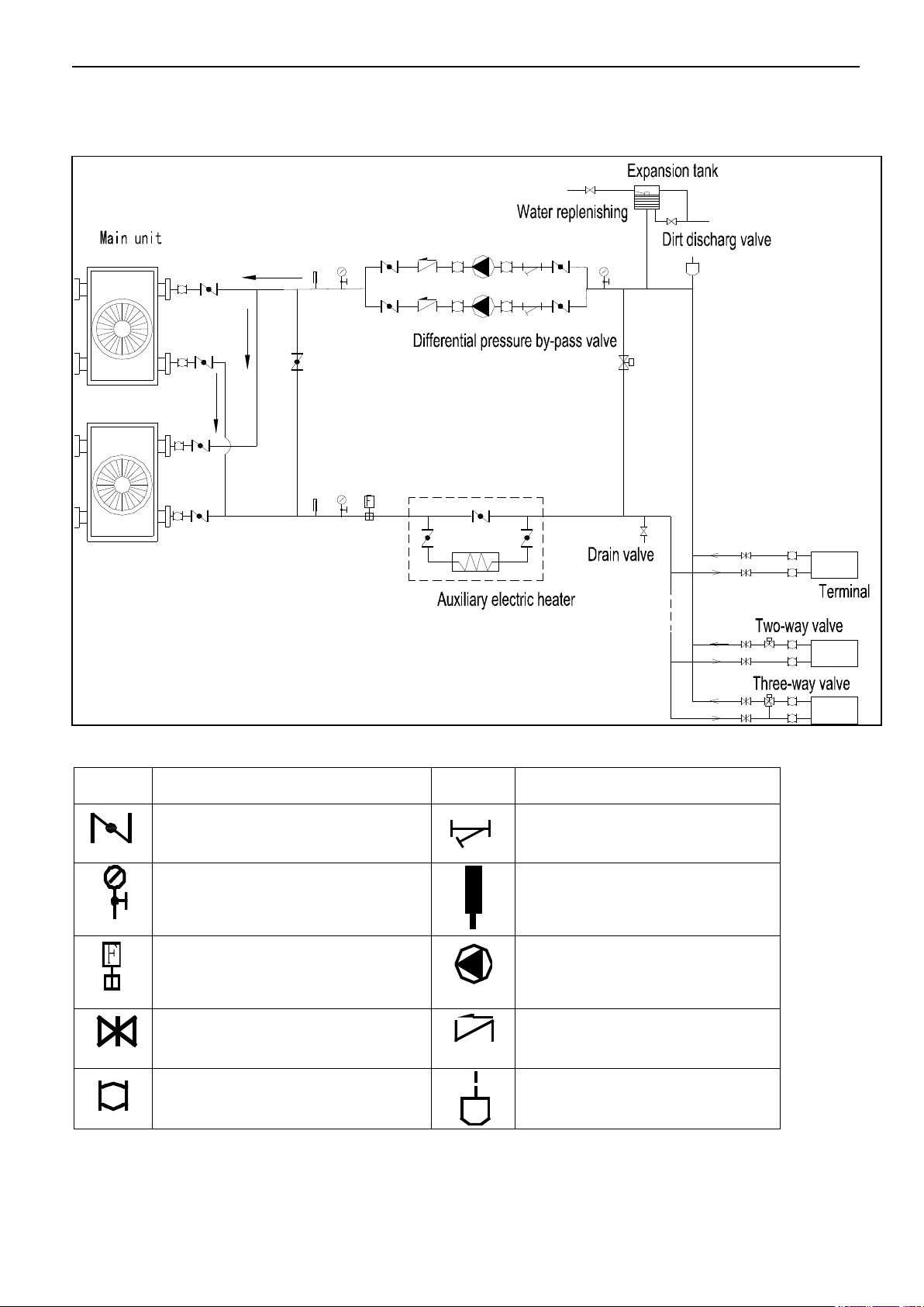
Symbol
Symbol explanation
Symbol
Symbol explanation
Stop valve
Y-shaped filter
Pressure gauge
Thermometer
Water flow switch
Circulating pump
Gate valve
Check valve
Flexible joint
Automatic discharge valve
2. Pipe connection drawing
2.1MGBT-F25W/RN1,MGBT-D25W/RN1,MGBT-F30W/RN1,MGBT-D30W/RN1
The table below describes the symbols.
26
MCAC-ATSM-2014-09 Aqua tempo power series tropical air-cooled scroll chiller 50Hz
Symbol
Symbol explanation
Symbol
Symbol explanation
Stop valve
Y-shaped filter
Pressure gauge
Thermometer
Water flow switch
Circulating pump
Gate valve
Check valve
Flexible joint
Automatic discharge valve
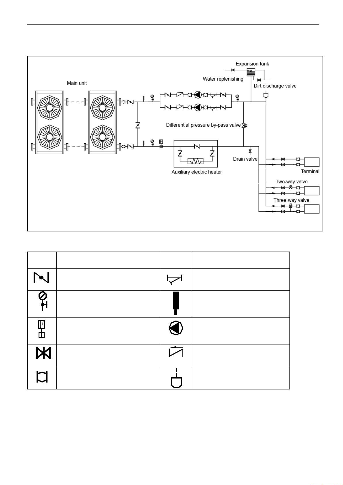
2.2 MGBT-F60W/RN1
The table below describes the symbols.
27
Aqua tempo power series tropical air-cooled scroll chiller 50Hz MCAC-ATSM-2014-09
Symbol
Symbol explanation
Symbol
Symbol explanation
Stop valve
Y-shaped filter
Pressure gauge
Thermometer
Water flow switch
Circulating pump
Gate valve
Check valve
Flexible joint
Automatic discharge valve
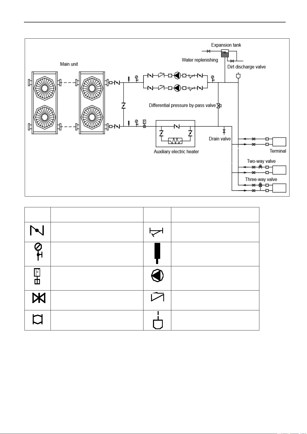
2.3 MGBT-D60W/RN1
The table below describes the symbols.
28

MCAC-ATSM-2014-09 Aqua tempo power series tropical air-cooled scroll chiller 50Hz
Symbol
Symbol explanation
Symbol
Symbol explanation
Stop valve
Y-shaped filter
Pressure gauge
Thermometer
Water flow switch
Circulating pump
Gate valve
Check valve
Flexible joint
Automatic discharge valve
2.4 MGBT-F120W/RN1
The table below describes the symbols.
29

Aqua tempo power series tropical air-cooled scroll chiller 50Hz MCAC-ATSM-2014-09
Symbol
Symbol explanation
Symbol
Symbol explanation
Stop valve
Y-shaped filter
Pressure gauge
Thermometer
Water flow switch
Circulating pump
Gate valve
Check valve
Flexible joint
Automatic discharge valve
2.5 MGBT-F180W/RN1
The table below describes the symbols.
30

MCAC-ATSM-2014-09 Aqua tempo power series tropical air-cooled scroll chiller 50Hz
Symbol
Symbol explanation
Symbol
Symbol explanation
Stop valve
Y-shaped filter
Pressure gauge
Thermometer
Water flow switch
Circulating pump
Gate valve
Check valve
Flexible joint
Automatic discharge valve
2.6 MGBT-F250W/RN1
The table below describes the symbols.
31

Aqua tempo power series tropical air-cooled scroll chiller 50Hz MCAC-ATSM-2014-09
Compressor A
Compressor B
Low pressure cylinder A
Low pressure cylinder B
4-way valve A
4-way valve B
Condenser
Evaporator
(Double-pipe heat exchanger)
Fan
Water outlet
Water inlet
EXV
EXV
Shell and tube
evaporator
Condenser
Water flow direction
Compressor B
low pressure cylinder B
4-Way valve A
Fan A
EEV
Capillary
EEV
Capillary
Fan B
4-Way valve B
Compressor A
low pressure cylinder A
3. Refrigeration system drawing
3.1 MGBT-F25W/RN1, MGBT-D25W/RN1, MGBT-F30W/RN1 ,MGBT-D30W/RN1
Each module has two compressors with one separate unit, one double-pipe evaporator for two refrigerant
systems.
3.2 MGBT-F60W/RN1
Each module has two compressors with one separate unit, one shell and tube evaporator for two refrigerant
systems.
32

MCAC-ATSM-2014-09 Aqua tempo power series tropical air-cooled scroll chiller 50Hz
Shell and tube evaporator
Condenser
Water flow direction
Compressor
B
low pressure cylinder B
4-Way valve A
Fan A
EEV
Capillary
EEV
Capillary
Fan B
4-Way valve B
Compressor
A1 digital
low pressure cylinder A
Compressor
A2
3.3 MGBT-D60W/RN1
Each module has three compressors with one separate units, one shell and tube evaporator for two
refrigerant systems.
3.4 MGBT-F120W/RN1
Each module has four compressors with two separate unit, one shell and tube evaporator for four refrigerant
systems.
33

Aqua tempo power series tropical air-cooled scroll chiller 50Hz MCAC-ATSM-2014-09
Shell and tube
evaporator
Condenser
Water flow direction
Compressor B
low pressure cylinder B
4-Way valve A
Fan A
EEV
Capillary
EEV
Capillary
Fan B
4-Way valve B
Compressor A
low pressure cylinder A
Unit 2
Unit 1
Shell and tube evaporator
Condenser
Water flow direction
Compressor B
low pressure cylinder B
4-Way valve A
Fan A
EEV
Capillary
EEV
Unit 2
Unit 3
Capillary
Fan B
4-Way valve B
Compressor A
low pressure cylinder A
Unit 1
3.5 MGBT-F180W/RN1
Each module has six compressors with three separate unit, one shell and tube evaporator for six refrigerant
systems.
3.6 MGBT-F250W/RN1
Each module has eight compressors with two separate unit, one shell and tube evaporator for four refrigerant
systems
34

MCAC-ATSM-2014-09 Aqua tempo power series tropical air-cooled scroll chiller 50Hz
Shell and tube
evaporator
Condenser
Water flow direction
Compressor B1
low pressure cylinder B
4-Way valve A
Fan A
EEV
Capillary
EEV
Capillary
Fan B
4-Way valve B
Compressor A1
low pressure cylinder A
Unit 2
Unit 1
Compressor A2
Compressor B2
35

Aqua tempo power series tropical air-cooled scroll chiller 50Hz MCAC-ATSM-2014-09
Attached Drawing (I) Electric Drawing of Main Unit and Auxiliary Unit
XP8
XP7
XS8
XS7
T
3
B
T
3
A
HEAT_A
L_PRO(2B)
H_PRO(B)
K1(B)
1 2
ON
PMV(B)
QUERY
L_PRO(2A)
H_PRO(A)
K1(A)
CN18(WHIT E)
POWER
CN20(RED)
TRANS I N
CN15(WHITE)
CN11(BLACK)
COMP(B) S.V(B )
COMP(A) S.V(A )
CN9
PUMP
CN7
HEAT
CN1(WHITE)
PMV(A)
CN2(RED)
PMV(B)
CN21
TBH2
CN3(RED)
WATER_PR O
CN5
H&L_PRO
COM(I)
COM(O)
CN6
CN8
CN10
CN12 CN13
CN14
CT1
CURRENT(A )
CT2
CURRENT(B )
PMV(A)
CN19(WHITE)
TRANS OUT
FAN _H
FAN _L
(YE LLOW)
(BLUE)
COMP B
2
1
5
21
3
6
22
4
T3
A1
A2
T2
T1
HEAT_B
RE D
H2 P 1 P 2H1
X T 3
S1
S2
T3A T3 B T 4
XT4
XT5
R
T
6
R
T
7
CN22
TBH1
T61
T62
L_PRO(1A)
L_PRO(1B)
COMP A
2
5
21
3
6
22
4
T3
A1
A2
T2
T1
FAN
( )
(U)
(V)
(W)
(U)
(V)
(W)
Y&G
POWER IN
Y & G
S1
16 -W AY DAI L SWI TCH FUNC TI O N
1
2
SW IT CH
FU NC TIO N
D I GITA L
M O DULE
N O RMAL
M O DULE
2- WA Y J UMP SWIT C H F UNC T ION
DA I L S WIT C H
AD DR ES S
R E D
W H I T E
B LU E
S2
Q
P
(E)
GRAY
7- WA Y
TE RM INA L
XT 2
4- WA Y
TE RM INA L
H E A T
P U M P
BL U EBL U EBL U E
BL U E
YE L L O W
YE L L O W
Y
E
L
L
O
W
B
L
A
C
K
(E F FEC T O N N O.0 M ODU L E)
(ON/OFF SIGNAL!)
L O W V O LT A GE S IG N AL
D O N ' T C O N N E CT H IG H V OL T AG E !
ORANGE
RED
ELE CTRI C EXPA N SIV E VALV E (B )
HIG H PRE SSUR E
PRO TEC TOR B
LOW P RESSU RE
PRO TEC TO R 2 B
PURPLE
LOW P RESSU RE
PRO TEC TO R 2A
YELLOW
HIG H P RESS URE
PRO TEC TO R A
TEM P P ROT ECTO R
SWI TCH A
IN-LET WATER TEMP. SENSOR
ANTI-FREEZIN G TEMP. SENSOR
TEM P P ROT ECTO R
SWI TCH B
LOW P RESSU RE
PRO TEC TO R 1B
LOW P RESSU RE
PRO TEC TO R 1A
RED BLACK
CONDENSER
TEMP B
CONDENSER
TEMP A
TOT AL OUT - LET
WAT ER TEM P .
UNI T O UT- LE T
WAT ER TEM P .
CR AN K
COMPRESSOR A
Y& G
BLUE
BL AC K
AC CO NTACTO R
BLACK
BLUE
RED
WH IT E
CR AN K
COMPRESSOR B
AC CO NTACTOR
BLACK
BLUE
RED
WH IT E
Y& G
Y& G
S.V(A)
4-VALVE A
S.V(B)
4-VALVE B
MIDDL E
WIRE JO IN T
MIDDL E
WIRE JO IN T
PURPLE
BLUE
B
LACK
BLACK
MIDDL E
WIRE JO IN T
XT6
WHITE
BLUE
RED
BLACK
BL U EBL U EBL U E
BL U E
YE L L O W
YE L L O W
OR A N G E
BLUE
PU R P LE
XP9
XS9
XP9
OUTDOOR TEMP SENSOR
T
4
XP10
XS10
WHITE
OUT DO OR WI RI NG DI AG RA M
GRAY
GRAY
4-WA Y TERMI NA L
XT1
W1 W2
Q
P
(E)
HIGH
N
LOW
BLACK
BALCK
BLACK
BLACK
RED
WHITE
FAN CAP
CN23(WHITE)
ON/OFF
MIDDL E
WIRE JO IN T
XT7
RED
PWM
CN17
PWM PRESSURE
RELIF VALVE
RED
RED RED
RED
BLACK
RED
BLUE
RY8RY7
10K
T-COMP SHORT
BE CO NNEC T ED TH E
COR RES PON D TE RMIN A L
4. Wiring diagram
4.1 MGBT-F25W/RN1, MGBT-D25W/RN1, MGBT-F30W/RN1, MGBT-D30W/RN1
36

MCAC-ATSM-2014-09 Aqua tempo power series tropical air-cooled scroll chiller 50Hz
Attached picture (I) Electric Drawing of Main Unit and
Auxiliary Unit
XP8
XP7
XS8
XS7
T
3
B
T
3
A
FAN B
HEAT_A
L_PRO (2B)
H_PRO (B)
K1(B )
1 2
ON
KM1
PMV(B)
QUERY
L_PRO (2A)
H_PRO (A)
K1(A )
CN18(WHITE)
POWER
CN2 0(RED)
TRANS IN
PWM
CN1 7
CN1 5(WHITE)
CN1 1(BLACK)
COMP(B) S.V(B)
COMP(A) S.V(A)
CN9
PUM P
CN7
HEA T
CN1(WHITE)
PMV(A)
CN2(RED)
PMV(B)
CN2 1
TBH 2
CN3(RED)
WATER_PRO
CN5
H&L_PRO
COM(I)
COM(O)
CN6
CN8
CN1 0
CN1 2 CN 13
CN1 4
CT1
CURRENT(A)
CT2
CURRENT(B)
PMV(A)
CN1 9(WHITE)
TRANS OUT
FAN_H
RY7
FAN_L
RY8
(YELLOW)
(BLUE)
COMP B
2
1
5
21
3
6
22
4
T3
A1
A2
T2
T1
HEAT_B
RED
H2 P1 P2H1
XT 4
S1
S2
T3A T3B T4
XT5
XT6
R
T
6
R
T
7
CN2 2
TBH 1
T61
T62
L_PRO (1A)
L_PRO (1B)
COMP A
2
5
21
3
6
22
4
T3
A1
A2
T2
T1
FAN A
KM2
(U )
(V )
(W )
(U )
(V )
(W )
Y&G
4-WA Y TERMINAL
XT1
POWER I N
Y& G
S1
16-WAY DAIL SWITCH FUNCTION
1
2
SWITCH
FUNCTION
RE SE RVE
NO RM AL
2-WAY JUMP SWITCH FUNCTION
DAIL SWITCH
ADDRESS
BLUE
WHITE
RED
RE D
WH ITE
BL UE
BL ACK
S2
(FACTORY SET TING)
4-WAY
TERMINAL
HEAT
PUMP
BLU EBLU EBLU E
BLU E
YEL LO W
YEL LO W
(EFFECT ON NO.0 MODULE)
(O N/O F F SIGNAL! )
ORANGE
RED
ELECTRI C EXPANSIVE
VA LVE(B)
HI GH P RES SUR E
PR OTE CTO R B
LO W PR E SSU R E
PR OTE CTO R 2B
PURPLE
LO W PR E SSUR E
PR OTE CTO R 2 A
YELLOW
HI GH P RESS UR E
PR OTE CTO R A
TE MP PR OTEC TOR
SW ITC H A
IN-LE T WATE R TEMP. SENSO R
ANTI-FREEZING T EMP. SEN SOR
TE MP P ROTE C TO R
SW ITC H B
LO W PR ESSU RE
PR OTE CTO R 1B
LO W PR E SSUR E
PR OTE CTO R 1 A
RED
BLACK
CONDENSER
TEMP B
CONDENSER
TEMP A
TO TAL O UT-L ET
WAT E R T EMP .
UN IT O U T-L E T
WAT E R T EMP .
RELAY
RELAY
CRANK
COMPRESSOR A
Y&G
RED
RED
WHITE
RED
RED
Y&G
BLACK
RED
WHITE
AC C O N T A C T O R
BLACK
WHITE
BLUE
RED
RED
BLUE
RED
WHITE
CRANK
COMPRESSOR B
RED
AC CONTACT O R
BLACK
WHITE
BLUE
RED
BLUE
RED
WHITE
Y&G
Y&G
S.V (A)
4-V ALV E A
S.V (B)
4-V ALV E B
MIDDL E
WIR E JOIN T
MIDDL E
WIR E JOIN T
ORANGE
PURPL E
BLUE
BLACK
BLACK(N)
BLACK
BLACK
MIDDL E
WIR E JOIN T
XT 7
RED
RED
WHITE
BLUE
RED
BLACK
BLU EBLU EBLU E
BLU E
YEL LO W
YEL LO W
ORA NG E
BLUE
PUR PL E
RED
XP9
XS9
XP9
OUTDOOR T EM P SENSO R
T
4
XP10XS10
WHITE
BLACK
BLACK(N)
RED
WHITE
BLUE
BLACK
BLACK
RED
3
2
2
2
2
BROWN
BROWN
4
2
2
BROWN
BROWN
RED
RED
BLACK(N)
OUTDOOR WIRING DI AGRAM
Q
P
(E)
GRAY
7-WAY
TERMINAL
XT2
Y
E
L
L
O
W
B
L
A
C
K
LOW VO LTAGE SIGNAL
DON'T CONNECT HIGH VOLTAGE !
G
R
A
Y
GRAY
W1 W2
Q
P
(E)
CN2 3(WHITE)
ON/OFF
B
L
U
E
R
E
D
TO NEX T
MO DULE
TO TIM E R
ON/ O F F
PR OVI DE
BY USE R
BE CON N ECTE D TH E
CO RRE SPON D TE R MIN A L
4.2 MGBT-F60W/RN1
37

Aqua tempo power series tropical air-cooled scroll chiller 50Hz MCAC-ATSM-2014-09
Attached picture (I) Electric Drawing of Main Unit and Auxiliary Unit
XP8
XP7
XS8
XS7
T
3
B
T
3
A
HEAT_A1
PMV(B)
QUER Y
CN18 (WHIT E)
POWE R
CN20(RED)
TRAN S IN
PWM
CN17
CN15(WHITE)
CN9(WHITE)
COMP .B2 COMP. A2
COMP .A1 S.V(A )
CN24
PUMP
CN16
ALAR M
CN8(WHITE )
ANTI-F REEZI NG
CN3(YELLOW )
PH_PRO
CN2( RED)
PMV( B)
COM( I)
COM(O )
CN6
CN27 CN10 CN22 CN32
CN14
PMV(A)
CN11(RED)
POWE R OUT
FANA
CN30
FANB
CN31
(Y ELLO W)
(RED)
COMP B
2
1
5
21
3
6
22
4
T3
A1
A2
T2
T1
HEAT_B
ORA NGE
H2 P1 P 2H1
XT4
S1
SW3
ICOMP- B2
XT5
XT6
RT6
R
T
7
CN23 (WHIT E)
ON/O FF
RT 4
RT 5
COMP A1
2
5
21
3
6
22
4
T3
A1
A2
T2
T1
FAN B
(U)
(V)
(W)
(U)
(V)
(W)
Y&G
4-WAY TER MINAL
XT1
P O W E R I N
Y&G
S1
16- WAY DA IL SW ITCH F UNCTIO N
DAI L SWIT CH
ADD RES S
BLUE
WHITE
RED
RED
WHI TE
BLU E
BLA CK
4-W AY
TER MIN AL
HEAT
PUMP
BLU EBLU EBLU E
BLU E
YEL LOW
YEL LOW
(EFFEC T ON NO. 0 MOD ULE)
(ON/ OFF SIGN AL! )
ELE CTRIC E XPA NSIVE
VAL VE(B)
IN -LE T W ATE R TEM P. S EN SOR
AN TI- FRE EZ ING TE MP. S ENS OR
RED BLAC K
CO ND ENS ER
TE MP B
CO NDEN SER
TE MP A
TOTAL OU T-LE T WATER TEM P.
UNIT OU T-LE T WATER TEM P.
CRA NK
COMPRESSOR A1
Y&G
ORANGE
BLACK
WHITE
BLUE
RED
RED
BLUE
RED
WHI TE
CRA NK
COMPRESSOR B
RED
AC CO NTA CT OR
BLACK
WHITE
BLUE
RED
BLUE
RED
WHI TE
Y&G
Y&G
S.V(A)
4-VALVE A
S.V(B)
4-VALVE B
MID DLE
WIR E JO INT
MID DLE
WIR E JO INT
ORA NGE
PURPLE
BLUE
MID DLE
WIR E JO INT
XT7
RED
WHITE
BLUE
RED
BLACK
BLU EBLU EBLU E
BLUE
YELL OW
YEL LOW
BLUE
PUR PLE
RED
XP9XP9
T
4
WHITE
Q
P
(E)
GRAY
7-W AY
TER MIN AL
XT2
Y
E
L
L
O
W
B
L
A
C
K
LOW VO LTAGE SI GNA L
DON 'T CON NECT HIG H VOLT AGE!
G
R
A
Y
GRAY
W1 W 2
Q
P
(E)
B
L
A
C
K
R
E
D
PRO VID E
BY U SER
AC CO NTA CT OR
CN5
H&L_ PRO
CN1( WHIIT E)
PMV( A)
CN28 (RED)
HEAT /COO L
CN4(RED)
WATER_ PRO
CN21 CN26 CN33 CN35CN34
1 2 3
ON
3 4
SW2
1 2
OFF
T3A T3B T4 ICOMP- A2ICOMP- A1 ICOMP- B1
CN7
(BLU E)
HEAT
CN12(BLACK)
COMP .B1 S.V(B )
RED
CN19(WHITE)
TRAN S OUT
L_PRO(2B )
H_PRO(B)
K1(B)
L_PRO(2A )
H_PRO(A)
CURRENT( A2)
ORANGE
RED
HIG H PR ESSU RE
PRO TEC TOR B
LOW PRE SSUR E
PRO TEC TOR 2 B
PURPLE
LOW PRE SSUR E
PRO TEC TOR 2 A
YELLOW
HIG H PR ESSU RE
PRO TEC TOR A
TEM P PR OTEC TOR
SWI TCH A2
TEM P PR OTEC TOR
SWI TCH B1
K1(A1)
TEM P PR OTEC TOR
SWI TCH A1
K1(A2)
CURRENT( B1)
CURRENT( A1)
XS9
L_PRO(1B )
L_PRO(1 A)
RED
LOW PRE SSUR E
PRO TEC TOR 1 B
PURPLE
LOW PRE SSUR E
PRO TEC TOR 1 A
MAIN BOARD
CURRENT BOARD
L2L3L4 L1
CN6
CN7
CN8
CN5
CN4
HEAT_A2
COMP A2
2
5
21
3
6
22
4
T3
A1
A2
T2
T1
(U)
(V)
(W)
CRA NK
COMPRESSOR A2
RED
BLACK
WHITE
BLUE
RED
BROWN
BLUE
RED
WHI TE
Y&G
AC CO NTA CT OR
HIGH
BLUE
HIGH
FAN A
Y&G
L3
L1
L2
PWM PRESSURE
RELIF VALVE
BROW N
LOW
BROWN
BLACKBLACK
BLUE
RED
RED
BLACK
RED
BROWN BLUE
BROWN
BROWN
BLUE
WHITE
BLACK
WHITE RED
BLACK
BLUE
S2 ON:COOL ONLY OFF:R&C
S3 ON:DIGITAL OFF:FIXED
S4 ON:H-EEPROM OFF:NORMAL
S5 ON:C-EEPROM OFF:NORMAL
S7 ON:REMOTECONTROL OFF:WIRECONTROL
S8 ON:LOW TEMP.MODE OFF:NORMAL
S9 ON:30KW OFF:65/130/200/260KW
S2 S3S4 S5 S7 S8 S9
B
R
O
W
N
R
E
D
RED
ORANGE
ORANGE
O U T D O O R WI R I N G DI A G R A M
R
E
D
B
L
U
E
SW3
1 2 3
ON
3 4
SW2
1 2
ON
S2 S3S4 S5 S7 S8 S9
SW2/SW3 FUCTION DEFINATION
ON
OFF
PRO VID E
BY U SER
DEFAULT SETTING
REMOTETURN OFF
OFF
ON/O FF
S7
ON
REMOTE FUCTIONSETTING
REMOTECOOL
ON OFF
REMOTE HEAT
ON OFF
(O N/ O FF S IG N AL ! )
4.3 MGBT-D60W/RN1
38

MCAC-ATSM-2014-09 Aqua tempo power series tropical air-cooled scroll chiller 50Hz
4.4 MGBT-F120W/RN1
39

Aqua tempo power series tropical air-cooled scroll chiller 50Hz MCAC-ATSM-2014-09
Auxiliary Unit
KM1
A
B
C
A
N
B
C
XT1
KM2
A B
C
KM3
A B
C
KM4
A
B
C
Y/G
XT3
(T 1)
(T 3)
(T 2)
(T 1)
(T 3)
(T 2)
(T 1)
(T 3)
(T 2)
(T 1)
(T 3)
(T 2)
KM5
A
B
C
KM6
A
B
C
(T 1)
(T 3)
(T 2)
(T 1)
(T 3)
(T 2)
H1
H2
P1
P2
XT9
HEATER
PUMP
XP8
XP7
XS8
XS7
T
3
-
1
B
T
3
-1A
L_PR O(1B2)
H_PRO(1B)
K1(1B)
1 2
ON
XP9
XS9
L_PR O(1A2)
H_PRO(1A)
K1(1A)
POWER
TRANS IN
CN 11( BL ACK)
CO MP( B) S.V (B )
CO MP( A) S.V( A)
H&L_P RO
COM(O )
CN 6
CN 8
CN 10
CN 12
CN 14
CT 1
CU RRE NT (A)
CT 2
CU RRE NT (B)
TRANS OUT
BL AC K
BL UE
WH IT E
RE D
S1
S2
T
U
1
CN 5
CN 19
(W HI TE)
CN 20
(R ED )
CN 18
(W HI TE )
S. V( 1A)
S. V( 1B)
KM 2
1 (MAIN)
CN 7
CN 9
HEAT
PUMP
#
L_PR O(1A1)
L_PR O(1B1)
Q
P
(E)
XP18
XP17
XS18
XS17
T
3
-
3
B
T
3
-3A
L_PR O(3B2)
H_PRO(3B)
K1(3B)
1 2
ON
XP19
XS19
CH EC K
L_PR O(3A2)
H_PRO(3A)
K1(3A)
POWER
TRANS IN
CO MP( B) S.V (B ) C OM P(A )S .V(A )
H&L_P RO
COM(O )
CN 6
CN 8
CN 12
CN 14
CT 1
CU RRE NT (A)
CT 2
CU RRE NT (B)
TRANS OUT
S1
S2
T
U
3
CN 5
S. V( 3A)
S. V( 3B)
KM 6
KM 5
3 (SLAVE)
CN 7
CN 9
HEAT
PUMP
#
L_PR O(3A1)
L_PR O(3B1)
XP13
XP12
XS13
XS12
T
3
-
2
B
T
3
-
2
A
L_PR O(2B2)
H_PRO(2B)
K1(2B)
1 2
ON
XP14
XS14
L_PR O(2A2)
H_PRO(2A)
K1(2A)
POWER
TRANS IN
CO MP( B) S.V (B )
CO MP( A) S.V( A)
H&L_PR O
COM(O )
CN 6
CN 8
CN 12
CN 14
CT 1
CU RRE NT (A)
CT 2
CU RRE NT (B)
TRANS OUT
S1
S2
T
U
2
CN 5
KM 4
KM 3
2 (SLAVE)
CN 7
CN 9
HEAT
PUMP
#
L_PR O(2A1)
L_PRO( 2B1)
TB H2- 1
TB H1- 1
TB H2- 2
TB H1- 2
TB H2- 3
TB H1- 3
RE D
RE D
RE D
RE D
T
4
-
1
XP10XS10
T
4
-
2
XP15
XS15
T
4
-
3
XP20
XS20
S1
16-WA Y DAI L SWITC H F UNCTI ON
1
2
SWITC H
FUNCTIO N
RESERV E
NORMAL
2-WA Y JUMP SW ITCH FUNCTIO N
DAIL SWITC H
ADDRES S
S2
(F AC TORY S ET TING )
RED
BLACK
POWER IN
WHITE
BLUE
Hea t1A
COMP1A
BLUE
RED
WHITE
BROWN
BLUE
RED
RED
BLACK
BROWN
BROWN
BROWN
Hea t1B
Hea t2A
Heat 2B
Hea t3A
Heat 3B
BROWN
BLUE
RED
WHITE
RED
BLUE
RED
WHITE
RED
BLUE
RED
WHITE
RED
BLUE
RED
WHITE
RED
BLUE
RED
WHITE
BROWN
BLUE
RED
BROWN
BLUE
RED
BROWN
BLUE
RED
BROWN
BLUE
RED
BROWN
BLUE
RED
COMP1B COMP2A COMP 2B COMP3A COMP3B
Y/G Y/G
Y/G Y/G Y/G
MI DDL E
WI RE J OIN T
ORANGE
RED
PURPLE
YELLOW
HI GH P RESS UR E
PR OTE CT OR 1 B
LO W PR ESSU RE
PR OTE CT OR 1 B1
LO W PR ESSU RE
PR OTE CT OR 1 A1
HIGH PRESSURE
PROTECTOR 1A
TEMP PROTECTOR
SWITCH 1A
TE MP P ROTE CT OR
SW ITC H 1B
LO W PR ESSU RE
PR OTE CT OR 1 B2
LO W PR ESSU RE
PR OTE CT OR 1 A2
TO TAL OU T-L ET
WA TER TE MP.
AN TI- FR EEZ ING
TE MP. SE NSO R 1
IN -LE T W ATE R
TE MP. SE NSO R 1
UN IT O UT -LE T
WA TER TE MP. 1
RED
BLACK
WHITE
OUTDOOR
TEMP.1
CONDENSER
TEMP.1B
CONDENSER
TEMP.1A
CH EC K
TR AN S1
BL UE
BL UE
YE LL OW
YE LL OW
BLUE
(EFFEC T ON NO. 0 MODULE)
(ON /OF F SIG N AL)
LOW VOLTAGE SIGNAL
DON'T CONNECT HIGH VOLTAGE!
GRAY
BLUE
GRAY
BLACK
YELLO W
TR AN S2
CN 19
(W HI TE)
CN 20
(R ED )
CN 18
(W HI TE )
BL AC K
BL UE
WH IT E
RE D
RE D
RE D
UN IT O UT -LE T
WA TER TE MP. 2
WHITE
OUTDOOR
TEMP.2
CONDENSER
TEMP.2B
CONDENSER
TEMP.2A
RED
BLACK
CH EC K
ORANGE
RED
PURPLE
YELLOW
HI GH P RESS UR E
PR OTE CT OR 2 B
LO W PR ESSU RE
PR OTE CT OR 2 B1
LO W PR ESSU RE
PR OTE CT OR 2 A1
HI GH P RESS UR E
PR OTE CT OR 2 A
TEMP PR OTECTOR
SWIT CH 2A
TEMP PR OTECTOR
SWITC H 2B
LO W PR ESSU RE
PR OTE CT OR 2 B2
LO W PR ESSU RE
PR OTE CT OR 2 A2
AN TI- FR EEZ ING
TE MP. SE NSO R 2
IN -LE T W ATE R
TE MP. SE NSO R 2
CN 15( WH ITE)
CN 11( BL ACK)
BLUE
OR ANG E
TR AN S3
CN 19
(W HI TE)
CN 20
(R ED )
CN 18
(W HI TE )
BL AC K
BL UE
WH IT E
RE D
UN IT O UT -LE T
WA TER TE MP. 3
WHITE
OUTDOOR
TEMP.3
CONDENSER
TEMP.3B
CONDENSER
TEMP.3A
RED
BLACK
ORANGE
RED
PURPLE
YELLOW
HI GH P RESS UR E
PR OTE CT OR 3 B
LO W PR ESS URE
PR OTE CT OR 3 B1
LO W PR ESSU RE
PR OTE CT OR 3 A1
HI GH P RESS UR E
PR OTE CT OR 3 A
TEMP PR OTECTOR
SWIT CH 3A
TEMP PR OTECTOR
SWIT CH 3B
LO W PR ESSU RE
PR OTE CT OR 3 B2
LO W PR ESSU RE
PR OTE CT OR 3 A2
AN TI- FR EEZ ING
TE MP. SE NSO R 3
IN -LE T W ATE R
TE MP. SE NSO R 3
CN 15( WH ITE)
CN 11( BL ACK)
BLUE
OR ANG E
S. V( 2A)
S. V( 2B)
Y&G
WH ITE
BL ACK
KM 1
CN 15( WH ITE)
FA N_LFA N_H
OR AN GE
WH IT E
7- WAY
TE RMI NAL
XT 8
W1 W2
Q
P
(E)
XT4
MI DDL E
WI RE J OIN T
XT5
MI DDL E
WI RE J OIN T
XT6
MI DDL E
WI RE J OIN T
XT1 1
MI DDL E
WI RE J OIN T
XT2
MI DDL E
WI RE J OIN T
XT7
MI DDL E
WI RE J OIN T
BROWN
RED
FAN3A PRO
FAN1A PRO
FAN2A PRO
PURPL E
PU RPL E
PU RPL E
RED
RED
BLUE
MI DDL E
WI RE J OI NT
XT1 0
OUTDOOR WIRING DIAGRAM
FAN3B PRO
FAN2B PRO
FAN1B PRO
BROWN
BLUE
BLUE
PURPLE
BLUE
PURPLE
PURPLE
BLACK
BLACKBLACKBLA CKBLACKBLACK
FA N_LFA N_H FA N_LFA N_H
BLA CK
3# FAN_L
1# FAN_H
1# FAN_L
2# FAN_H
2# FAN_L
3# FAN_H
BROWN
BLA CK
BLA CK
BLACK
RED
GRAY
RED
W1
CONNE CT NEXT M ODULE
W2
RED
RED/BLUE
RED/BLUE
TO T IMER
4.5 MGBT-F180W/RN1
40

MCAC-ATSM-2014-09 Aqua tempo power series tropical air-cooled scroll chiller 50Hz
Attached Drawing (I) Electric Drawing of Main Unit and Auxiliary Unit
4.6 MGBT-F250W/RN1
41

Aqua tempo power series tropical air-cooled scroll chiller 50Hz MCAC-ATSM-2014-09
Attached Drawing (II) Networking Communication Schematic of Main Unit and
Auxiliary Unit
A B
C
N
H2 P 1 P 2H1
T h e l e n gth o f w i r e
s h o u l d b e s h o rte r
t h a n 5 0 0 m
100Ω
Bl ac k
Yel lo w
Gr ay
Query
Fault
N ote s
The w ir ing d ia gram of au xiliary h e ater an d
pum p is ju st fo r re fe renc e , plea se f ol lo w t he
in st ru cti on s o f c orrespond ing a ux iliary
he ate r pr od uc ts.
Ple as e c hoose su ch ac ce s so ry a s p ow e r
wire , sw i tch of a ux iliar y h ea ter a cc or ding to
th e actu al p aram et er o f p ro du ct s a nd na ti onal
H2 P 1 P 2H1
H2 P 1 P 2H1
120Ω
RVV-300/500 4X10+1X6mm
2
RVV-300/500 4X10+1X6mm
2
RVV-300/500 4X10+1X6mm
2
POWER 380V 3N 50Hz
POWER 380V 3N~
50Hz
POWER 380V 3N~50Hz
POWER 380V 3N~50Hz
5 Networking communication wiring diagram
5.1 MGBT-F25W/RN1, MGBT-D25W/RN1, MGBT-F30W/RN1, MGBT-D30W/RN1
42

MCAC-ATSM-2014-09 Aqua tempo power series tropical air-cooled scroll chiller 50Hz
Attached picture (II) Networking Communication Schematic of Main Unit and
Auxiliary Unit
A B
C
N
H2 P 1 P 2H1
T h e leng t h o f w i re
s h oul d b e sho rte r
t h a n 500 m
1 0 0Ω
Bl ac k
Yello w
Gr ay
Query
Fault
N ote s
Th e wiri ng diag ra m o f a ux iliar y h ea te r a nd
p um p is j us t fo r r ef er en ce ,plea s e f ollo w the
instru ctio ns o f c orr es po n ding au xi liar y
he a ter pr od u cts .
Pl ea se ch o os e s uc h a cc esso ry as p ow er
wire , s witch o f a uxilia ry h e at er a c co rd in g to
th e actua l p a rame te r of p ro du ct s a nd n at ion a l
H2 P 1 P 2H1
H2
P1 P 2H 1
1 2 0Ω
5.2 MGBT-F60W/RN1
43

Aqua tempo power series tropical air-cooled scroll chiller 50Hz MCAC-ATSM-2014-09
Attached picture (II) Networking Communication Schematic of Main Unit and Auxiliary Unit
A B
C
N
Th e l e ng t h o f wi r e
sh o u ld b e s h or t er
th a n 5 00 m
10 0Ω
Blac k
Yellow
Gray
Query
Fault
Not es
The w iring d iagram o f auxil iary he ater and
pum p is jus t for ref erence , pleas e foll ow the
ins tructi ons of co rresp onding aux iliar y
hea ter p roduct s.
Ple ase ch oose su ch acc essor y as power
wir e , swi tch of au xilia ry heate r accord ing t o
the ac tual p arame ter of pro ducts a nd natio nal
12 0Ω
H2 P1 P2H1
H2 P 1 P2H1
H2 P1 P2H1
5.3 MGBT-D60W/RN1
44

MCAC-ATSM-2014-09 Aqua tempo power series tropical air-cooled scroll chiller 50Hz
Attached Drawing (II) Networking Communication Schematic of Main Unit and
Auxiliary Unit
A B
C
N
H2 P 1 P2H1
100Ω
Black
Yellow
Gray
Query
Fault
Notes
The w iring dia gram of auxiliar y heater a nd
pum p is jus t for ref erenc e ,plea se fo llow t he
ins truct ions o f correspond ing au xiliary
heat er pr oducts.
Plea se cho ose suc h accessor y as powe r
wir e , swi tch of a uxiliary heat er accordi ng to
the act ual par ameter o f produ cts and nat ional
H2 P 1 P2H1
H2 P 1 P2H1
120Ω
POWER 380-415V 3N~50Hz
POWER 380-415V 3N~50Hz
POWER 380-415V 3N~50Hz
POWER 380-415V 3N~50Hz
5.4 MGBT-F120W/RN1
45

Aqua tempo power series tropical air-cooled scroll chiller 50Hz MCAC-ATSM-2014-09
Attached Drawing (II) Networking Communication Schematic of Main Unit and
Auxiliary Unit
A B
C
N
H2 P1 P2H1
120Ω
W1
W2
H2 P 1 P 2H 1
W1
W2
H2 P 1 P2H1
W1
W2
The l e ngth o f wi r e
sho uld b e sh o rter
tha n 5 00m
100Ω
Bla ck
Yello w
Gra y
Query
Fault
Note s
The wir ing di agra m of au xil iary h eate r and
pum p is j ust f or refere nce , plea se f ollo w the
ins truc tio ns of cor resp ond ing aux ilia ry
hea ter pro duc ts.
Ple ase ch oose s uch acc esso ry as pow er
wir e , swit ch o f au xiliar y hea ter ac cordi ng t o
the ac tual pa ramet er of p rodu cts a nd na tion al
TO TI MER
ON/ OFF
BLU E
RED
BLU E
RED
BLU E
RED
5.5MGBT-F180W/RN1
46

MCAC-ATSM-2014-09 Aqua tempo power series tropical air-cooled scroll chiller 50Hz
Attached Drawing (II) Networking Communication Schematic of Main Unit and Auxiliary Unit
A B
C
N
Th e le ng t h of wi r e
sh ou ld b e sh o rt er
th an 5 00 m
Black
Yellow
Gray
Notes
The wir ing diag ram of auxil iary hea ter and
pump is j ust for ref erence , please f ollow th e
instr uction s of corr espondi ng auxil iary
heate r produc ts.
Pleas e choose such a ccesso ry as power
wire , sw itch of au xiliary h eater acc ording to
the ac tual par ameter of p roduct sa nd nation al
H2 P1 P2H 1
H2 P1
P2H1
H2 P1 P 2H1
12 0Ω
5.6MGBT-F250W/RN1
47

Aqua tempo power series tropical air-cooled scroll chiller 50Hz MCAC-ATSM-2014-09
6.Exploded view
6.1 MGBT-F25W/RN1
48

MCAC-ATSM-2014-09 Aqua tempo power series tropical air-cooled scroll chiller 50Hz
No.
Part Name
Qty
No.
Part Name
Qty
1
Net
2
24.6
Transformer
1
2
Right seal plate ass'y D of condenser
1
24.7
7-terminal Block
1
3
Tube heat exchanger
1
24.8
Wire joint,4p
1
4
Right seal plate ass'y A of condenser
1
24.9
Wire joint
1
5
Input pipe ass'y of unit B
1
24.10
Terminal block
4
5.1
Electronic expansion valve
1
24.11
Capacitor
1
6
Input pipe ass'y II of unit B
1
25
Scroll Compressor
2
7
Input pipe ass'y I of unit A
1
26
Drainage pan holder
2
7.1
Electronic expansion valve
1
27
Electronic control box door
1
8
Output pipe ass'y of unit A
1
28
Welding parts water tray
1
9
Four-way valve ass'y of unit A
1
29
Electronic control box mounting plate
2
9.1
Four-way valve set
1
30
Condenser components of unit A
1
9.2
Meter connector
3
31
Cover
1
9.3
Muffler
1
32
Ass'y C of left seal plate,condenser
1
10
Input pipe ass'y II of unit A
1
33
Condenser components of unit B
1
11
Four-way valve ass'y of unit B
1
34
Motor holder
2
11.1
Four-way valve set
1
35
Side sealed board
7
11.2
Meter connector
3
36
Clapboard supporting board
3
11.3
Muffler
1
37
Motor bracket bonding parts
1
12
Suction pipe ass'y A
1
38
Cover
2
12.1
Meter connector
1
39
Motor
1
13
Suction pipe ass'y B
1
40
Axial fan
1
13.1
Meter connector
1
41
Top cover
1
14
Support board
2
42
Middle partition plate
1
15
Cover
1
43
Top cover
1
16
Cover board
2
44
Sealed board
1
17
Temp sensor clip
6
45
Rear Cover
1
18
Sensor clamp
1
46
Front cover
1
19
The welding part of small baseplate
1
47
About clapboard
2
49

Aqua tempo power series tropical air-cooled scroll chiller 50Hz MCAC-ATSM-2014-09
No.
Part Name
Qty
No.
Part Name
Qty
20
Ass'y B of left seal plate,condenser
1
48
Wired controller
1
21
Accumulator cylinder
2
49
Total water temperature mouth components
1
22
Base
1
50
EXV solenoid
2
23
Base ass'y
1
51
Pipe temperature sensor ass'y
2
24
Electronic control box assembly of Air-cooled
module
1
52
Pipe temperature sensor ass'y
4
24.1
Welding together pieces of electronic control box
1
53
Room temp. sensor ass'y
1
24.2
Mounting plate with pieces of electrical
1
54
Discharge temperature sensor
2
24.3
30KW Air-cooled module control board
assembly
1
55
Pressure controller
2
24.4
Relay
2
56
Pressure controller
2
24.5
Contactor
2
6.2 MGBT-D25W/RN1
50

MCAC-ATSM-2014-09 Aqua tempo power series tropical air-cooled scroll chiller 50Hz
整机电路接线图
No.
Part Name
Qty
No.
Part Name
Qty
1
Net
2
26.4
Relay
2
2
Right seal plate ass'y D of condenser
1
26.5
Contactor
2
3
Tube heat exchanger
1
26.6
Transformer
1
4
Right seal plate ass'y A of condenser
1
26.7
7-terminal Block
1
5
Input pipe ass'y of unit B
1
26.8
Wire joint,4p
1
5.1
Electronic expansion valve
1
26.9
Wire joint
1
6
Input pipe ass'y II of unit B
1
26.10
Terminal block
4
7
Input pipe ass'y I of unit A
1
26.11
Capacitor
1
7.1
Electronic expansion valve
1
27
Scroll Compressor
1
8
D machines take over the assembly solenoid valve
1
28
Drainage pan holder
2
8.1
Pressure-relief-valve
1
29
Electronic control box door
1
9
Output pipe ass'y of unit A
1
30
Welding parts water tray
1
10
Four-way valve ass'y of unit A
1
31
Sensor clamp
1
10.1
Four-way valve set
1
32
Condenser components of unt A
1
10.3
Meter connector
3
33
Cover
1
10.4
Muffler
1
34
Ass'y C of left seal plate,condenser
1
11
Input pipe ass'y II of unit A
1
35
Condenser components of unit B
1
12
Four-way valve ass'y of unit B
1
36
Motor holder
2
12.1
Four-way valve set
1
37
Side sealed board
7
12.2
Meter connector
3
38
Clapboard supporting board
3
12.3
Muffler
1
39
Motor bracket bonding parts
1
13
Suction pipe ass'y A
1
40
Cover
2
13.1
Meter connector
1
41
Motor
1
14
Suction pipe ass'y of unit D
1
42
Axial fan
1
14.1
Meter connector
1
43
Top cover
1
15
Support board
2
44
Middle partition plate
1
16
Cover
1
45
Top cover
1
17
Compressor's cover
2
46
Sealed board
1
51

Aqua tempo power series tropical air-cooled scroll chiller 50Hz MCAC-ATSM-2014-09
No.
Part Name
Qty
No.
Part Name
Qty
18
Cover of screw
4
47
Rear Cover
1
19
Temp sensor clip
6
48
Front cover
1
20
The welding part of small baseplate
1
49
About clapboard
2
21
Ass'y B of left seal plate,condenser
1
50
Wired controller
1
22
Accumulator cylinder
2
51
Total water temperature mouth
components
1
23
Digital compressor
1
52
EXV solenoid
2
24
Base
1
53
Pipe temperature sensor ass'y
2
25
Base ass'y
1
54
Pipe temperature sensor ass'y
4
26
electronic control box assembly of Air-cooled
module
1
55
Room temp. sensor ass'y
1
26.1
Welding together pieces of electronic control box
1
56
Discharge temperature sensor
2
26.2
Mounting plate with pieces of electrical
1
57
Pressure controller
2
26.3
30KW Air-cooled module control board assembly
1
58
Pressure controller
2
52

MCAC-ATSM-2014-09 Aqua tempo power series tropical air-cooled scroll chiller 50Hz
6.3 MGBT-F30W/RN1
53

Aqua tempo power series tropical air-cooled scroll chiller 50Hz MCAC-ATSM-2014-09
No.
Part Name
Qty
No.
Part Name
Qty
1
Net
2
24.7
7-terminal Block
1
2
Right seal plate ass'y D of condenser
1
24.8
Wire joint,4p
1
3
Tube heat exchanger
1
24.9
Wire joint
1
4
Right seal plate ass'y A of condenser
1
24.10
Terminal block
4
5
Input pipe ass'y of unit B
1
24.11
Capacitor
1
5.1
Electronic expansion valve
1
25
Scroll Compressor
2
6
Input pipe ass'y II of unit B
1
26
Drainage pan holder
2
7
Input pipe ass'y I of unit A
1
27
Electronic control box door
1
7.1
Electronic expansion valve
1
28
Welding parts water tray
1
8
Output pipe ass'y of unit A
1
29
Electronic control box mounting plate
2
9
Four-way valve ass'y of unit A
1
30
Condenser components of unt A
1
9.1
Four-way valve set
1
31
Cover
1
9.2
Meter connector
3
32
Ass'y C of left seal plate,condenser
1
9.3
Muffler
1
33
Condenser components of unit B
1
10
Input pipe ass'y II of unit A
1
34
Motor holder
2
11
Four-way valve ass'y of unit B
1
35
Side sealed board
7
11.1
Four-way valve set
1
36
Clapboard supporting board
3
11.2
Meter connector
3
37
Motor bracket bonding parts
1
11.3
Muffler
1
38
Cover
2
12
Suction pipe ass'y A
1
39
Motor
1
12.1
Meter connector
1
40
Axial fan
1
13
Suction pipe ass'y B
1
41
Top cover
1
13.1
Meter connector
1
42
Middle partition plate
1
14
Support board
2
43
Top cover
1
15
Cover
1
44
Sealed board
1
16
Cover board
2
45
Rear Cover
1
17
Temp sensor clip
6
46
Front cover
1
18
Sensor clamp
1
47
About clapboard
2
19
The welding part of small baseplate
1
48
Wired controller
1
54

MCAC-ATSM-2014-09 Aqua tempo power series tropical air-cooled scroll chiller 50Hz
No.
Part Name
Qty
No.
Part Name
Qty
20
Ass'y B of left seal plate,condenser
1
49
Total water temperature mouth components
1
21
Accumulator cylinder
2
50
EXV solenoid
2
22
Base
1
51
Pipe temperature sensor ass'y
2
23
Base ass'y
1
52
Pipe temperature sensor ass'y
4
24
electronic control box assembly of Air-cooled
module
1
53
Room temp. sensor ass'y
1
24.1
Welding together pieces of electronic control box
1
54
Discharge temperature sensor
2
24.2
Mounting plate with pieces of electrical
1
55
Pressure controller
2
24.3
30KW Air-cooled module control board assembly
1
56
Pressure controller
2
24.4
Relay
2
57
Compressor electric heater
2
24.5
Contactor
2
58
Refrigerant
6.2
24.6
Transformer
1
6.4 MGBT-D30W/RN1
55

Aqua tempo power series tropical air-cooled scroll chiller 50Hz MCAC-ATSM-2014-09
56

MCAC-ATSM-2014-09 Aqua tempo power series tropical air-cooled scroll chiller 50Hz
No.
Part Name
Qty
No.
Part Name
Qty
1
Net
2
33
Cover
1
2
Right seal plate ass'y D of condenser
1
34
Ass'y C of left seal plate,condenser
1
3
Tube heat exchanger
1
35
Condenser components of unit B
1
4
Right seal plate ass'y A of condenser
1
36
Motor holder
2
5
Input pipe ass'y of unit B
1
37
Side sealed board
7
5.1
Electronic expansion valve
1
38
Clapboard supporting board
3
6
Input pipe ass'y II of unit B
1
39
Motor bracket bonding parts
1
7
Input pipe ass'y I of unit A
1
40
Cover
2
7.1
Electronic expansion valve
1
41
Motor
1
8
D machines take over the assembly solenoid valve
1
42
Axial fan
1
8.1
Pressure-relief-valve
1
43
Top cover
1
9
Output pipe ass'y of unit A
1
44
Middle partition plate
1
10
Four-way valve ass'y of unit A
1
45
Top cover
1
10.1
Four-way valve
1
46
Sealed board
1
10.2
Meter connector
3
47
Rear Cover
1
10.3
Muffler
1
48
Front cover
1
11
Input pipe ass'y II of unit A
1
49
About clapboard
2
12
Four-way valve ass'y of unit B
1
50
Wired controller
1
12.1
Four-way valve
1
51
Total water temperature mouth
components
1
12.2
Meter connector
3
52
EXV solenoid
2
12.3
Muffler
1
53
Pipe temperature sensor ass'y
2
13
Suction pipe ass'y A
1
54
Pipe temperature sensor ass'y
4
13.1
Meter connector
1
55
Room temp. sensor ass'y
1
14
Suction pipe ass'y of unit D
1
56
Discharge temperature sensor
2
14.1
Meter connector
1
57
Pressure controller
2
15
Support board
2
58
Pressure controller
2
16
Cover
1
32
Cover
1
57

Aqua tempo power series tropical air-cooled scroll chiller 50Hz MCAC-ATSM-2014-09
No.
Part Name
Qty
No.
Part Name
Qty
17
Compressor's cover
2
33
Ass'y C of left seal plate,condenser
1
18
Cover of screw
4
34
Condenser components of unit B
1
19
Temp sensor clip
6
35
Motor holder
2
20
The welding part of small baseplate
1
36
Side sealed board
7
21
Ass'y B of left seal plate,condenser
1
37
Clapboard supporting board
3
22
Accumulator cylinder
2
38
Motor bracket bonding parts
1
23
Digital compressor
1
39
Cover
2
24
Base
1
40
Motor
1
25
Base ass'y
1
41
Axial fan
1
26
electronic control box assembly of Air-cooled module
1
42
Top cover
1
26.1
Welding together pieces of electronic control box
1
43
Middle partition plate
1
26.2
Mounting plate with pieces of electrical
1
44
Top cover
1
26.3
30KW Air-cooled module control board assembly
1
45
Sealed board
1
26.4
Relay
2
46
Rear Cover
1
26.5
Contactor
2
47
Front cover
1
26.6
Transformer
1
48
About clapboard
2
26.7
7-terminal Block
1
49
Wired controller
1
26.8
Wire joint,4p
1
50
Total water temperature mouth
components
1
26.9
Wire joint
1
51
EEV solenoid
2
26.10
Terminal block
4
52
Pipe temperature sensor ass'y
2
26.11
Capacitor
1
53
Pipe temperature sensor ass'y
4
27
Scroll Compressor
1
54
Room temp. sensor ass'y
1
28
Drainage pan holder
2
55
Discharge temperature sensor
2
29
Electronic control box door
1
56
Pressure controller
2
30
Welding parts water tray
1
57
Pressure controller
2
31
Sensor clamp
1
58
Cover
1
32
Condenser components of unt A
1
6.5 MGBT-F60W/RN1
58

MCAC-ATSM-2014-09 Aqua tempo power series tropical air-cooled scroll chiller 50Hz
、45
59

Aqua tempo power series tropical air-cooled scroll chiller 50Hz MCAC-ATSM-2014-09
21.1
21.2
21.3
21.4
21.5
21.6
21.7
21.8
21.9
21.10
No.
Part Name
Qty
No.
Part Name
Qty
1
Condenser fixed plate ass'y of unit A
1
28
A machine back to the tube components
1
2
Condenser side board
2
29
B machine back to the tube components
1
3
A unit condenser ass'y
1
30
A unit four-way valve assembly machine
1
4
B unit condenser ass'y
1
30.1
Four-way valve kit (RoHS)
1
5
Mid horizontal support
2
30.2
Pressure controller
1
6
Fixed board
2
30.3
Pressure switch
1
7
Mid upright support
2
30.4
Meter connector
2
8
Capacitor card
2
31
B-way valve assembly
1
9
A unit evaporator input pipe ass'y
1
31.1
Four-way valve kit (RoHS)
1
10
B unit evaporator input pipe ass'y
1
31.2
Pressure controller
1
11
Cover
1
31.3
Pressure switch
1
12
Cover
1
31.4
Meter connector
2
13
Triangle reinforcement ass'y
8
32
Drainage pan ass'y
1
14
Reinforcement board
4
33
Middle partition plate
2
15
Base
1
34
Net
2
16
Compressor
2
35
Net
4
17
Cover
1
36
Top upright support
2
18
Wiring terminal fixing board
1
37
Condenser seal connector
1
19
Cover
1
38
Top cover
2
20
Cover
1
39
Axial fan
2
21
electronic control box assembly of Air-cooled module
1
40
Motor mounting plate welded
2
21.1
Air-cooled module control board components
1
41
Three-phase asynchronous motor
2
21.2
Relay
2
42
Mid horizontal support
2
21.3
AC contactor
2
43
Motor bracket ass'y
4
21.4
AC contactor
2
44
Condenser seal connector
1
21.5
Transformer
1
45
Compressor wire joint
2
21.6
7-terminal Block
1
46
Condenser fixed plate ass'y of unit B
1
21.7
Wire joint,4p
1
47
EXV solenoid coil
2
21.8
Wire joint
1
48
Discharge temperature sensor
2
21.9
Terminal block
3
49
Room temperature sensor ass'y T41
1
60

MCAC-ATSM-2014-09 Aqua tempo power series tropical air-cooled scroll chiller 50Hz
No.
Part Name
Qty
No.
Part Name
Qty
21.11
Welding together pieces of electronic control box
1
50
Pipe temp. sensor ass'y
3
22
Wire casing
0.5
51
Pipe temperature sensor ass'y
1
23
Vapor-liquid separator
2
52
Pipe temp. sensor ass'y
2
24
Shell and tube evaporator
1
53
Compressor electric heater
2
25
Cover
1
54
Earth wire
2
26
Pole
4
55
Wired controller
1
27
Electrical box door
1
56
Total water temperature mouth components
1
6.6 MGBT-D60W/RN1
61

Aqua tempo power series tropical air-cooled scroll chiller 50Hz MCAC-ATSM-2014-09
、40
62

MCAC-ATSM-2014-09 Aqua tempo power series tropical air-cooled scroll chiller 50Hz
63

Aqua tempo power series tropical air-cooled scroll chiller 50Hz MCAC-ATSM-2014-09
No.
Part Name
Qty
No.
Part Name
Qty
1
A combination of pieces of fixed plate condenser
1
27
Electrical box door
1
2
Condenser side board
2
28
A machine back to the tube components
1
3
Condenser ass'y A
1
29
A machine back to the tube ass'y
1
3.1
Condenser ass'y of A
1
30
A four-way valve assembly machine
1
4
Condenser ass'y B
1
30.1
4-way valve
1
4.1
Condenser ass'y of B
1
30.2
Pressure controller
1
5
Middle beam
2
30.3
Pressure controller
1
6
Fixed board
2
31
Four-way valve ass'y of A
1
7
Mid upright support
2
31.1
4-way valve
1
8
Pipe fixing clamp
2
31.2
Pressure controller
1
9
Evaporator input pipe ass'y
1
31.3
Pressure controller
1
9.1
Electronic expansion valve
1
32
Drainage pan ass'y
1
10
Evaporator input pipe ass'y
1
33
Middle partition plate
2
10.1
Electronic expansion valve
1
34
Net
2
11
Cover
1
35
Net
4
12
Cover
1
36
Top upright support
2
13
Triangle reinforcement ass'y
8
37
Condenser seal connector
1
14
Reinforcement board
4
38
Top cover
2
15
Base
1
39
Axial flow fan
2
16
Supporting ass'y of compressor
2
40
A unit discharging pipe ass'y
1
17
Cover
1
41
Motor
2
18
Wiring terminal fixing board
1
42
Mid horizontal support
2
19
Cover
1
43
Motor bracket ass'y
4
20
Cover
1
44
Condenser seal connector
1
21
Outdoor unit electrical box ass'y
1
45
Unload valve ass'y
1
21.1
Electrcial box welding part
1
46
Fixed plate with the condenser B
1
21.2
Outdoor main board ass'y
1
47
EEV solenoid coil
2
21.3
Contactor
2
48
Discharge temp sensor
3
21.4
Outdoor unit currrent detection ass'y
1
49
Room temp sensor ass'y T41
1
21.5
Wire joint,11p
1
50
Coil temp. sensor ass'y
2
21.6
Wire joint,4p
1
51
Temp.sensor ass'y
1
21.7
Capacitor
2
52
Coil temp sensor ass'y
3
21.9
Terminal block
3
53
Compressor electric heater
1
21.10
Wire joint
1
55
4-Ways valve solenoid
2
21.11
Transformer
1
56
Refrigerant
13
21.12
Relay
3
57
Compressor
1
21.13
AC contactor
1
58
Compressor
1
22
Wire Groove
0.5
59
Compressor
1
23
Vapor-liquid separator
2
60
Gas balance pipe of compreesor
1
24
Shell and tube evaporator
1
61
Oil balance pipe ass'y
1
25
Cover
1
62
Total water temperature mouth components
1
26
Pole
4
63
Accessory- wired controller(English)
1
64

MCAC-ATSM-2014-09 Aqua tempo power series tropical air-cooled scroll chiller 50Hz
6.7 MGBT-F120W/RN1
65

Aqua tempo power series tropical air-cooled scroll chiller 50Hz MCAC-ATSM-2014-09
No.
Part Name
Qty
No.
Part Name
Qty
1
The top beam
2
35.1
Four-way valve set
1
2
The condenser seal fittings. II
2
35.3
Meter connector
2
3
Iron nets fixed plate. II
2
36
Fixed plate
4
4
Protect net around
4
37
Pipe fixing clamp
6
5
pole
4
38
Welding parts water tray
2
6
Trough fixation plate
4
39
Condenser seal plate ass'y
2
7
Left right panel by. II
1
40
Condenser parts of unit A
2
8
Iron nets fixed board I
2
40.1
Condenser ass'y of unit A
1
9
Protect network and
4
40.2
Flute-shaped tube ass'y of unit A
1
10
In the frame beams
2
40.3
Distributor ass'y of unit A condenser
1
11
Cover
1
41
Condenser fixed plate ass'y of unit A
2
12
electronic control box assembly of Air-cooled
module
1
42
Motor bracket bonding parts
8
12.1
Welded parts of electric control box
1
43
Three-phase asynchronous motor
4
12.2
Outdoor control board ass'y
1
44
Axial fan
4
12.3
Relay
4
45
Condenser fixed plate ass'y of unit B
2
12.4
AC contactor
4
46
Unit B condenser parts
2
12.5
AC contactor
4
46.1
Condenser ass'y of unit B
1
12.6
Transformer
2
46.2
B-flute-shaped tube assemblies
1
12.7
7-terminal Block
1
46.3
Distributor ass'y of unit B condenser
1
12.8
Wire joint,4p
1
47
Evaporator connection pipe ass'y of unit
A1 of four-way valve
1
12.9
Wire joint
1
47.1
Pressure controller
1
12.10
Terminal block
6
48
Four-way valve ass'y of unit B2
1
12.11
Electrical mounting plate II
1
48.1
Four-way valve
1
13
Cover plate of electric control box
1
48.2
Pressure controller
1
14
Cover
1
48.3
Meter connector
2
15
Cover
1
49
Evaporator connection pipe ass'y of unit
B2 of four-way valve
1
16
Cover
1
49.1
Pressure controller
1
17
Welded parts of base
1
50
Suction pipe ass'y
1
18
Compressor
4
50.1
Pressure controller
1
19
Storage tank bottom II weld installation
1
51
Suction pipe ass'y
3
20
Compressor installed base II weld
1
51.1
Pressure controller
1
21
Reinforcement board
4
52
Four-way valve ass'y of unit A2
1
22
Triangle reinforcement ass'y
8
52.1
Four-way valve
1
23
Piping support-unit
2
52.2
Pressure controller
1
24
Vapor-liquid separator
4
52.3
Pressure controller
1
25
Shell and tube evaporator
1
52.4
Meter connector
2
26
Storage tank bottom I weld parts installation
1
53
I sealed connector condenser
2
66

MCAC-ATSM-2014-09 Aqua tempo power series tropical air-cooled scroll chiller 50Hz
No.
Part Name
Qty
No.
Part Name
Qty
27
Compressor installed base I weld
1
54
Roof rack beams II
1
28
Vertical beams in the frame
2
55
Top cover
4
29
I left panel
3
56
I beam roof rack
1
30
Evaporator inlet pipe ass'y of unit B2
1
57
Vertical beam roof rack
2
30.1
Electronic expansion valve
1
58
Total water temp. sensor ass'y
1
31
Inlet pipe ass'y of unit A2 evaporator
1
59
Wired controller
1
31.1
Electronic expansion valve to take over
1
60
Pipe temp. sensor ass'y
1
32
Input pipe ass'y of unit B1 evaporator
1
61
Pipe temp. sensor ass'y
4
32.1
Electronic expansion valve
1
62
Pipe temp. sensor ass'y
3
33
Input pipe ass'y of unit A1 evaporator
1
63
Pipe temp. sensor ass'y
1
33.1
Electronic expansion valve
1
64
Indoor temp. sensor ass'y T41
2
34
Four-way valve ass'y of unit B1
1
65
Pipe temp. sensor ass'y
2
34.1
Four-way valve set
1
66
Discharge temp. controller
4
34.3
Pressure controller
1
67
Electric heater of compressor
4
34.4
Meter connector
2
68
Refrigerant
26
35
Four-way valve ass'y of unit A1
1
69
Electronic expansion valve coil
4
67

Aqua tempo power series tropical air-cooled scroll chiller 50Hz MCAC-ATSM-2014-09
86
6.8 MGBT-F180W/RN1
68

MCAC-ATSM-2014-09 Aqua tempo power series tropical air-cooled scroll chiller 50Hz
No.
Part Name
Qty
No.
Part Name
Qty
1
Column
4
43.3
Meter connector
2
2
About the protective screen
4
44
Evaporator output pipe ass'y
1
3
Network Rail fixed plate II
2
44.1
Pressure controller
1
4
The middle beams
2
45
Evaporator output ass'y
1
5
Roof rack crossbar
2
45.1
Pressure controller
1
6
I sealed connector condenser
3
46
Evaporator output pipe ass'y
1
7
Vertical beam roof rack
2
46.1
Pressure controller
1
8
Condenser sealed connector II
3
47
Welded base plate
1
9
Roof rack beam welding parts
2
48
Left panel II
1
10
Top cover
6
49
Strengthened beams II
2
11
Rear Panel II
1
50
I left panel
3
12
Condenser output tube II
3
51
Panel fasteners II
8
13
In lane bridge I
2
52
Triangular reinforcement
12
14
Block I installed electronic control box
2
53
Trunking II
1
15
Block III electronic control box installed
2
54
II trunking cover
1
16
Rear Panel I
1
55
Four-way valve Ⅲ
1
17
Block II Electronic Control Box Installation
2
55.2
Pressure controller
1
18
Electronic control box cover panel B
1
55.3
Meter connector
2
19
electronic control box assembly of Air-cooled module
1
56
Condenser output transition tube(unit C)
1
19.1
Main control board ass'y
3
57
Condenser output transition tube(unit D)
1
19.2
Relay
6
58
Input pipe of evaporator ass'y(unit F)
1
19.3
AC contactor
6
59
I output tube condenser
3
19.4
AC contactor
6
60
Input pipe ass'y of evaporator(unit E)
1
19.5
Transformer
2
61
Input pipe ass'y of evaporator(unit D)
1
19.6
Transformer
1
62
Tube fixed plate Ⅳ
1
19.7
7-terminal Block
1
63
Shell and tube evaporator
1
19.8
Wire joint(4P)
1
64
Duct I
1
69

Aqua tempo power series tropical air-cooled scroll chiller 50Hz MCAC-ATSM-2014-09
No.
Part Name
Qty
No.
Part Name
Qty
19.9
Terminal block
8
65
I cover trunking
1
19.10
Terminal block
1
66
I panel fasteners
10
20
A cover board electronic control
1
67
I fixed plate tube
3
21
Seal plate condenser
6
68
Four-way valve assembly Ⅳ
3
22
Suction pipe ass'y
5
68.2
Pressure controller
1
23
Suction pipe ass'y
1
68.3
Meter connector
2
24
Condenser inlet pipe II
3
69
Vapor-liquid separator
6
25
I enter the tube condenser components
3
70
Vertical beam in the frame
2
26
Parts of unit B condenser
3
71
Front Panel
4
27
Condenser fixed plate ass'y of unit B
3
72
Strengthen the beam I
4
28
Axial fan
6
73
Network Rail fixed plate I
4
29
Three-phase asynchronous motor
5
74
Front grille
6
30
Three-phase asynchronous motor
1
75
Welded parts of installation base
6
31
Motor bracket bonding parts
12
76
Compressor
6
32
Installation base plate of condenser
12
77
Input pipe ass'y of evaporator(unit C)
1
33
Condenser fixed plate ass'y of unit A
3
78
I fixed plate throttle parts
2
34
Condenser parts of unit A
3
79
Input pipe ass'y of evaporator(unit B)
1
35
Tube fixed plate II
2
80
Input pipe ass'y of evaporator(unit A)
1
36
Welded parts of water pan
3
81
Target flow-volume controller
1
37
In lane bridge II
2
82
Total water temp. sensor ass'y
1
38
Tube fixed plate III
12
83
Pipe temp. sensor ass'y
9
39
Evaporator tube assembly output
1
84
Pipe temp. sensor ass'y
1
39.1
Pressure controller
1
85
Pipe temp. sensor ass'y
6
40
Evaporator tube assembly output
1
86
Wired controller
1
40.1
Pressure controller
1
87
Indoor temp. sensor ass'y T41
3
41
Evaporator tube assembly output
1
88
Discharge temp. controller
6
41.1
Pressure controller
1
89
Electrical heating belt compression
6
42
I four-way valve assembly
1
90
Electronic expansion valve coil
6
42.2
Pressure controller
1
91
Connection lines 1 of compressor
4
42.3
Meter connector
2
92
Connection lines 3 of compressor
2
43
Four-way valve assembly Ⅱ
1
93
Refrigerant
39
43.2
Pressure controller
1
6.9 MGBT-F250W/RN1
70

MCAC-ATSM-2014-09 Aqua tempo power series tropical air-cooled scroll chiller 50Hz
57、
71

Aqua tempo power series tropical air-cooled scroll chiller 50Hz MCAC-ATSM-2014-09
No.
Part Name
Qty
No.
Part Name
Qty
1
Triangular reinforcement
12
55
Vertical beam roof rack
2
2
Left panel II
1
56
Top cover
8
3
Vertical beam in the frame
2
58
Front panel II
1
4
Strengthened beams II
2
59
Fixed part of panel
1
5
I panel fasteners
10
60
Bottom pillar I
1
6
I left panel
3
61
Pipe support IV
1
7
Inputting pipe ass'y of A unit evaporator
1
62
Front panel I
1
7.1
Electronic expansion valve
1
63
Pipe fixing clamp
20
7.2
Strainer
2
64
Reinforcing board I
1
8
Discharging pipe ass'y
8
65
Pipe support III
1
9
Inputting pipe II of B unit evaporator
1
66
Compressor wire joint
2
10
Inputting pipe ass'y of B unit evaporator
1
67
Clamp II, pipe
9
10.1
Electronic expansion valve
1
68
Pipe support VII
8
10.2
Strainer
2
69
Electrical box ass'y of air modular
1
11
Column
4
69.1
Installation board II ass'y
1
12
Base welding parts
1
69.2
Installation board I ass'y
1
13
Base guard board
10
69.3
Electrical box welding parts
1
14
Inputting pipe ass'y of C unit evaporator
1
69.4
Current detction board ass'y of outdoor unit
2
14.1
Electronic expansion valve
1
69.5
Main board ass'y of outdoor unit
2
14.2
Strainer
2
69.6
Relay
6
15
Guard board welding parts
4
69.7
AC contactor
8
16
Four-way valve ass'y I
3
69.8
AC contactor
8
72

MCAC-ATSM-2014-09 Aqua tempo power series tropical air-cooled scroll chiller 50Hz
No.
Part Name
Qty
No.
Part Name
Qty
17
Outlet pipe ass'y I of condenser
3
69.9
Transformer
2
18
Inputting pipe ass'y of D unit evaporator
1
69.10
A Terminal Block
1
18.1
Electronic expansion valve
1
69.11
Wire joint,11p
1
18.2
Strainer
2
69.12
Wire joint, 1P
3
19
Four-way valve ass'y II
1
69.13
Wire joint,4p
1
20
Pipe support VI
1
69.14
Terminal block
7
21
Cover of wire casing III
1
70
Reinforcing board II
3
22
Wire casing III
1
71
Three-phase asynchronous motor
6
23
Installation base plate of condenser
16
72
Back support board of electric box
1
24
Outlet pipe ass'y II of condenser
1
73
Pipe support V
3
25
Wire casing I
1
74
Seal plate condenser
8
26
Cover of wire casing I
1
75
Motor
2
27
Shell-tube heat exchanger
1
76
Axial fan
8
28
Installation base welding parts of compressor
4
77
Motor bracket bonding parts
16
29
Inclined support II
1
78
Part B condenser
4
30
Pipe support I
1
79
A machine Condenser Parts
4
31
Pipe support II
2
80
Condenser fixed plate ass'y
4
32
Grille fixed board I
4
81
Condenser fixed plate ass'y
4
33
Front grille
8
82
Welding parts water tray
4
34
Fixed board II of grille
2
83
Cover II of electrical box
1
35
Compressor
8
84
Cover I of electrical box
1
36
Plastic washer
50
85
Support board of electrical box
2
37
Liquid separator
4
86
Output pipe of evaporator
1
38
Bottom column
4
87
Output pipe ass'y of evaporator(A)
1
39
Beam
2
88
Output pipe ass'y of evaporator(B)
1
40
Front Panel
5
89
Output pipe ass'y of evaporator(C)
1
41
Wire casing
1
90
Output pipe ass'y of evaporator(D)
1
42
Cover of wire casing II
1
91
Suction pipe ass'y of compressor
4
43
Fixed board of drainage
8
92
Suction pipe III
4
44
Connection parts of roof beams
4
93
Oil balance pipe ass'y I
4
45
Panel fasteners II
8
94
Reinforcing board
1
46
Inclined support I
1
95
Refrigerant
60
47
Wire support
3
96
Oil balance pipe ass'y II
4
48
Wiring bridge
3
97
Four-way valve coil
4
49
I sealed connector condenser
4
98
Compressor wire joint
4
50
Condenser sealed connector II
4
99
Electronic expansion valve coil
4
51
Network Rail fixed plate II
2
100
Total water temperature mouth components
1
52
About the protective screen
4
101
Target flow-volume controller
1
53
Upper beam
2
102
Electrical heating belt compression
8
54
Roof rack beam welding parts
3
73

Aqua tempo power series tropical air-cooled scroll chiller 50Hz MCAC-ATSM-2014-09
Part 2 Capacity tables and control system
Part 2 Capacity tables and control system ........................................................................................ 74
1. Capacity tables ......................................................................................................................... 75
1.1MGBT-F25W/RN1,MGBT-D25W/RN1
Cooling: .............................................................................................................................................................................. 75
1.2 MGBT-F30W/RN1, MGBT-D30W/RN1 ..........................................................................................................................77
1.3 MGBT-F60W/RN1 ......................................................................................................................................................... 79
1.4 MGBT-D60W/RN1 ........................................................................................................................................................ 81
1.5 MGBT-F120W/RN1....................................................................................................................................................... 83
1.6 MGBT-F180W/RN1....................................................................................................................................................... 85
1.7 MGBT-F250W/RN1....................................................................................................................................................... 87
2 Control system .......................................................................................................................... 89
2.1 MGBT-F25W/RN1, MGBT-D25W/RN1, MGBT-D30W/RN1, MGBT-F30W/RN1 ........................................................... 89
2.2 MGBT-F60W/RN1......................................................................................................................................................... 92
2.3 MGBT-D60W/RN1 ........................................................................................................................................................ 95
2.4 MGBT-F120W/RN1....................................................................................................................................................... 99
2.5 MGBT-F180W/RN1.....................................................................................................................................................103
2.6 MGBT-F250W/RN1.....................................................................................................................................................106
2.7 Remote control ..........................................................................................................................................................109
2.8 Control software ........................................................................................................................................................110
2.9 Lonworks gateway (Optional) .....................................................................................................................................130
74

MCAC-ATSM-2014-09 Aqua tempo power series tropical air-cooled scroll chiller 50Hz
Chilled water
outlet temp.
Ambient temp.(℃)
21.00
25.00
30.00
35.00
40.00
46.00
52.00
Capacity
Power
Capacity
Power
Capacity
Power
Capacity
Power
Capacity
Power
Capacity
Power
Capacity
Power
(℃)
KW
KW
KW
KW
KW
KW
KW
KW
KW
KW
KW
KW
KW
KW
5.00
31.35
8.19
29.52
8.44
27.85
8.71
26.32
8.97
24.66
9.42
22.69
9.89
20.42
10.39
6.00
32.41
8.32
30.49
8.58
28.73
8.84
27.13
9.11
25.45
9.57
23.44
10.05
21.12
10.55
7.00
33.54
8.49
31.52
8.75
29.68
9.02
28.00
9.30
26.29
9.77
24.24
10.25
21.87
10.77
8.00
34.57
8.74
32.46
9.01
30.54
9.29
28.78
9.58
27.06
10.06
24.97
10.56
22.55
11.09
9.00
35.55
8.83
33.35
9.10
31.34
9.38
29.51
9.67
27.77
10.16
25.66
10.66
23.20
11.20
10.00
36.90
8.96
34.58
9.24
32.47
9.52
30.54
9.82
28.77
10.31
26.62
10.82
24.09
11.36
11.00
37.93
9.05
35.51
9.33
33.31
9.62
31.31
9.91
29.52
10.41
27.34
10.93
24.77
11.48
12.00
38.79
9.18
36.29
9.46
34.01
9.76
31.93
10.06
30.15
10.56
27.95
11.09
25.35
11.64
13.00
39.49
9.25
36.90
9.54
34.55
9.84
32.41
10.14
30.63
10.65
28.43
11.18
25.81
11.74
14.00
40.47
9.32
37.79
9.61
35.35
9.90
33.13
10.21
31.34
10.72
29.11
11.26
26.46
11.82
15.00
40.99
9.36
38.23
9.65
35.73
9.95
33.46
10.26
31.68
10.77
29.47
11.31
26.81
11.88
1. Capacity tables
1.1MGBT-F25W/RN1,MGBT-D25W/RN1 Cooling:
Note:
The inlet/outlet water temperature difference is 5℃.
75

Heating:
Hot water
outlet temp.
Ambient temp.(℃)
-10
-6
-2 2 7
10
13
Capacity
Power
Capacity
Power
Capacity
Power
Capacity
Power
Capacity
Power
Capacity
Power
Capacity
Power
(℃)
KW
KW
KW
KW
KW
KW
KW
KW
KW
KW
KW
KW
KW
KW
39.00
18.34
5.76
22.92
6.54
26.97
7.27
29.96
7.90
32.57
8.32
36.47
8.82
41.95
9.52
41.00
17.72
5.87
22.18
6.67
26.12
7.42
29.06
8.06
31.62
8.49
35.35
8.99
40.58
9.71
42.00
17.21
5.99
21.56
6.81
25.43
7.57
28.32
8.23
30.85
8.66
34.42
9.18
39.45
9.91
43.00
16.79
6.12
21.07
6.95
24.88
7.72
27.73
8.39
30.24
8.84
33.69
9.37
38.54
10.12
44.00
16.47
6.24
20.69
7.09
24.45
7.88
27.29
8.57
29.80
9.02
33.13
9.56
37.84
10.32
45.00
16.23
6.37
20.41
7.24
24.16
8.04
26.99
8.74
29.50
9.20
32.75
9.75
37.33
10.53
46.00
15.91
6.43
20.04
7.31
23.74
8.12
26.56
8.83
29.06
9.29
32.20
9.85
36.64
10.64
47.00
15.44
6.56
19.47
7.46
23.10
8.28
25.87
9.00
28.33
9.48
31.33
10.05
35.60
10.85
48.00
14.83
6.76
18.73
7.68
22.24
8.53
24.93
9.27
27.34
9.76
30.18
10.35
34.23
11.18
49.00
14.02
7.03
17.73
7.99
21.08
8.87
23.66
9.65
25.97
10.15
28.62
10.76
32.40
11.62
50.00
13.12
7.38
16.61
8.39
19.77
9.32
22.22
10.13
24.41
10.66
26.86
11.30
30.35
12.20
Aqua tempo power series tropical air-cooled scroll chiller 50Hz MCAC-ATSM-2014-09
Note:
The inlet/outlet water temperature difference is 5℃.
76

MCAC-ATSM-2014-09 Aqua tempo power series tropical air-cooled scroll chiller 50Hz
Chilled water
outlet temp.
Ambient temp.(℃)
21.00
25.00
30.00
35.00
40.00
46.00
52.00
Capacity
Power
Capacity
Power
Capacity
Power
Capacity
Power
Capacity
Power
Capacity
Power
Capacity
Power
(℃)
KW
KW
KW
KW
KW
KW
KW
KW
KW
KW
KW
KW
KW
KW
5.00
33.59
8.81
31.63
9.08
29.84
9.36
28.20
9.65
26.42
10.13
24.31
10.64
21.88
11.17
6.00
34.72
8.94
32.66
9.22
30.79
9.51
29.07
9.80
27.27
10.29
25.11
10.80
22.63
11.34
7.00
35.93
9.13
33.77
9.41
31.80
9.70
30.00
10.00
28.17
10.50
25.97
11.03
23.43
11.58
8.00
37.04
9.40
34.78
9.69
32.72
9.99
30.84
10.30
28.99
10.82
26.76
11.36
24.16
11.92
9.00
38.09
9.49
35.73
9.79
33.58
10.09
31.62
10.40
29.75
10.92
27.49
11.47
24.85
12.04
10.00
39.53
9.63
37.05
9.93
34.79
10.24
32.73
10.56
30.83
11.08
28.52
11.64
25.81
12.22
11.00
40.63
9.73
38.05
10.03
35.69
10.34
33.54
10.66
31.63
11.19
29.29
11.75
26.54
12.34
12.00
41.56
9.87
38.88
10.18
36.44
10.49
34.22
10.82
32.30
11.36
29.94
11.92
27.16
12.52
13.00
42.31
9.95
39.54
10.26
37.02
10.58
34.73
10.90
32.82
11.45
30.46
12.02
27.65
12.62
14.00
43.36
10.02
40.48
10.33
37.87
10.65
35.49
10.98
33.58
11.53
31.19
12.10
28.35
12.71
15.00
43.92
10.07
40.97
10.38
38.29
10.70
35.85
11.03
33.95
11.58
31.57
12.16
28.73
12.77
1.2 MGBT-F30W/RN1, MGBT-D30W/RN1
Cooling:
Note:
The inlet/outlet water temperature difference is 5℃.
77

Heating:
Hot water outlet
temp.
Ambient temp.(℃)
-10
-6
-2 2 7
10
13
Capacity
Power
Capacity
Power
Capacity
Power
Capacity
Power
Capacity
Power
Capacity
Power
Capacity
Power
(℃)
KW
KW
KW
KW
KW
KW
KW
KW
KW
KW
KW
KW
KW
KW
39.00
19.89
6.13
24.86
6.97
29.25
7.74
32.50
8.42
35.33
8.86
39.57
9.39
45.50
10.14
41.00
19.22
6.26
24.06
7.11
28.34
7.90
31.52
8.59
34.30
9.04
38.34
9.58
44.02
10.35
42.00
18.67
6.38
23.39
7.26
27.58
8.06
30.72
8.76
33.46
9.22
37.34
9.78
42.79
10.56
43.00
18.22
6.52
22.86
7.40
26.98
8.23
30.08
8.94
32.80
9.41
36.54
9.98
41.81
10.77
44.00
17.86
6.65
22.44
7.55
26.53
8.39
29.61
9.12
32.32
9.60
35.94
10.18
41.04
10.99
45.00
17.60
6.78
22.14
7.71
26.21
8.57
29.28
9.31
32.00
9.80
35.52
10.39
40.49
11.22
46.00
17.26
6.85
21.74
7.79
25.76
8.65
28.81
9.40
31.52
9.90
34.92
10.49
39.74
11.33
47.00
16.75
6.99
21.12
7.94
25.06
8.82
28.06
9.59
30.73
10.10
33.99
10.70
38.61
11.56
48.00
16.09
7.20
20.31
8.18
24.13
9.09
27.05
9.88
29.66
10.40
32.74
11.02
37.13
11.90
49.00
15.21
7.49
19.23
8.51
22.87
9.45
25.67
10.27
28.17
10.81
31.05
11.46
35.15
12.38
50.00
14.23
7.86
18.02
8.93
21.45
9.92
24.10
10.79
26.48
11.36
29.13
12.04
32.92
13.00
Aqua tempo power series tropical air-cooled scroll chiller 50Hz MCAC-ATSM-2014-09
Note:
The inlet/outlet water temperature difference is 5℃.
78

MCAC-ATSM-2014-09 Aqua tempo power series tropical air-cooled scroll chiller 50Hz
Chilled water
outlet temp.
Ambient temp.(℃)
21.00
25.00
30.00
35.00
40.00
46.00
52.00
Capacity
Power
Capacity
Power
Capacity
Power
Capacity
Power
Capacity
Power
Capacity
Power
Capacity
Power
(℃)
KW
KW
KW
KW
KW
KW
KW
KW
KW
KW
KW
KW
KW
KW
5.00
67.17
17.61
63.25
18.16
59.67
18.72
56.40
19.30
52.85
20.27
48.62
21.28
43.76
22.34
6.00
69.44
17.89
65.33
18.44
61.57
19.01
58.14
19.60
54.54
20.58
50.23
21.61
45.25
22.69
7.00
71.87
18.25
67.54
18.82
63.60
19.40
60.00
20.00
56.34
21.00
51.95
22.05
46.85
23.15
8.00
74.09
18.80
69.57
19.38
65.44
19.98
61.68
20.60
57.98
21.63
53.51
22.71
48.32
23.85
9.00
76.18
18.98
71.46
19.57
67.16
20.18
63.24
20.80
59.51
21.84
54.99
22.93
49.71
24.08
10.00
79.06
19.27
74.10
19.86
69.58
20.48
65.45
21.11
61.66
22.17
57.03
23.28
51.61
24.44
11.00
81.27
19.46
76.09
20.06
71.38
20.68
67.09
21.32
63.27
22.39
58.58
23.51
53.08
24.68
12.00
83.13
19.74
77.76
20.35
72.88
20.98
68.43
21.63
64.60
22.71
59.88
23.85
54.31
25.04
13.00
84.61
19.90
79.08
20.52
74.04
21.15
69.46
21.81
65.64
22.90
60.91
24.04
55.31
25.24
14.00
86.72
20.04
80.97
20.66
75.74
21.30
70.99
21.96
67.15
23.05
62.38
24.21
56.71
25.42
15.00
87.83
20.14
81.93
20.76
76.57
21.40
71.70
22.06
67.90
23.17
63.14
24.33
57.46
25.54
1.3 MGBT-F60W/RN1
Cooling:
Note:
The inlet/outlet water temperature difference is 5℃.
79

Heating:
Hot water outlet
temp.
Ambient temp.(℃)
-10
-6
-2 2 7
10
13
Capacity
Power
Capacity
Power
Capacity
Power
Capacity
Power
Capacity
Power
Capacity
Power
Capacity
Power
(℃)
KW
KW
KW
KW
KW
KW
KW
KW
KW
KW
KW
KW
KW
KW
39.00
40.40
12.51
50.50
14.22
59.41
15.80
66.02
17.17
71.76
18.08
80.37
19.16
92.42
20.70
41.00
39.04
12.77
48.87
14.51
57.56
16.12
64.02
17.52
69.67
18.45
77.89
19.55
89.41
21.12
42.00
37.92
13.03
47.51
14.81
56.03
16.45
62.39
17.88
67.97
18.82
75.85
19.95
86.93
21.55
43.00
37.00
13.30
46.42
15.11
54.81
16.79
61.10
18.25
66.63
19.21
74.23
20.36
84.92
21.99
44.00
36.28
13.57
45.58
15.42
53.88
17.13
60.14
18.62
65.65
19.60
73.00
20.78
83.37
22.44
45.00
35.76
13.84
44.98
15.73
53.23
17.48
59.48
19.00
65.00
20.00
72.15
21.20
82.25
22.90
46.00
35.06
13.98
44.15
15.89
52.32
17.65
58.52
19.19
64.03
20.20
70.94
21.41
80.73
23.12
47.00
34.02
14.26
42.90
16.21
50.90
18.01
56.99
19.57
62.42
20.60
69.04
21.84
78.43
23.59
48.00
32.68
14.69
41.26
16.69
49.01
18.55
54.94
20.16
60.24
21.22
66.50
22.50
75.42
24.30
49.00
30.90
15.28
39.07
17.36
46.45
19.29
52.13
20.97
57.23
22.07
63.06
23.40
71.39
25.27
50.00
28.91
16.04
36.60
18.23
43.57
20.25
48.95
22.02
53.79
23.17
59.17
24.57
66.87
26.53
Aqua tempo power series tropical air-cooled scroll chiller 50Hz MCAC-ATSM-2014-09
Note:
The inlet/outlet water temperature difference is 5℃.
80

MCAC-ATSM-2014-09 Aqua tempo power series tropical air-cooled scroll chiller 50Hz
Chilled water
outlet temp.
Ambient temp.(℃)
21.00
25.00
30.00
35.00
40.00
46.00
Capacity
Power
Capacity
Power
Capacity
Power
Capacity
Power
Capacity
Power
Capacity
Power
(℃)
KW
kW
KW
kW
KW
kW
KW
kW
KW
kW
KW
kW
5.00
72.77
17.97
68.52
18.52
64.64
19.10
61.10
19.69
57.25
20.67
52.67
21.70
6.00
75.23
18.25
70.77
18.81
66.70
19.39
62.99
19.99
59.08
20.99
54.41
22.04
7.00
77.85
18.62
73.17
19.19
68.90
19.79
65.00
20.40
61.04
21.42
56.27
22.49
8.00
80.26
19.18
75.36
19.77
70.90
20.38
66.82
21.01
62.81
22.06
57.97
23.17
9.00
82.52
19.36
77.41
19.96
72.76
20.58
68.51
21.22
64.47
22.28
59.57
23.39
10.00
85.65
19.65
80.27
20.26
75.38
20.89
70.91
21.53
66.80
22.61
61.79
23.74
11.00
88.04
19.85
82.44
20.46
77.33
21.09
72.68
21.75
68.54
22.83
63.47
23.98
12.00
90.06
20.14
84.24
20.76
78.95
21.40
74.13
22.06
69.98
23.17
64.87
24.33
13.00
91.66
20.30
85.67
20.93
80.21
21.57
75.25
22.24
71.11
23.35
65.99
24.52
14.00
93.94
20.44
87.72
21.07
82.05
21.72
76.90
22.40
72.75
23.52
67.58
24.69
15.00
95.15
20.54
88.76
21.18
82.95
21.83
77.67
22.51
73.55
23.63
68.41
24.81
1.4 MGBT-D60W/RN1
Cooling
Note:
The inlet/outlet water temperature difference is 5℃.
81

Heating:
Hot water
outlet temp.
Ambient temp.(℃)
-10
-6
-2 2 7
10
13
Capacity
Power
Capacity
Power
Capacity
Power
Capacity
Power
Capacity
Power
Capacity
Power
Capacity
Power
(℃)
KW
kW
KW
kW
KW
kW
KW
kW
KW
kW
KW
kW
KW
kW
39.00
42.89
13.45
53.61
15.29
63.07
16.99
70.08
18.46
76.17
19.43
85.31
20.60
98.11
22.25
41.00
41.45
13.73
51.87
15.60
61.10
17.33
67.96
18.84
73.95
19.83
82.68
21.02
94.92
22.70
42.00
40.25
14.01
50.44
15.92
59.48
17.69
66.23
19.22
72.15
20.24
80.52
21.45
92.28
23.17
43.00
39.28
14.29
49.28
16.24
58.18
18.05
64.86
19.62
70.74
20.65
78.80
21.89
90.15
23.64
44.00
38.52
14.58
48.39
16.57
57.20
18.42
63.84
20.02
69.69
21.07
77.50
22.33
88.50
24.12
45.00
37.96
14.88
47.75
16.91
56.51
18.79
63.14
20.43
69.00
21.50
76.59
22.79
87.31
24.61
46.00
37.22
15.03
46.87
17.08
55.54
18.98
62.12
20.63
67.97
21.72
75.31
23.02
85.70
24.86
47.00
36.12
15.33
45.54
17.42
54.03
19.36
60.50
21.04
66.27
22.15
73.29
23.48
83.26
25.36
48.00
34.69
15.79
43.80
17.95
52.02
19.94
58.32
21.67
63.95
22.81
70.60
24.18
80.06
26.12
49.00
32.80
16.42
41.47
18.66
49.31
20.74
55.34
22.54
60.75
23.73
66.95
25.15
75.78
27.16
50.00
30.69
17.24
38.85
19.60
46.25
21.77
51.96
23.67
57.10
24.91
62.81
26.41
70.98
28.52
Aqua tempo power series tropical air-cooled scroll chiller 50Hz MCAC-ATSM-2014-09
Note:
The inlet/outlet water temperature difference is 5℃.
82

MCAC-ATSM-2014-09 Aqua tempo power series tropical air-cooled scroll chiller 50Hz
Chilled water
outlet temp.
Ambient temp.(℃)
21.00
25.00
30.00
35.00
40.00
46.00
52.00
Capacity
Power
Capacity
Power
Capacity
Power
Capacity
Power
Capacity
Power
Capacity
Power
Capacity
Power
(℃)
KW
KW
KW
KW
KW
KW
KW
KW
KW
KW
KW
KW
KW
KW
5.00
134.35
34.35
126.50
35.41
119.34
36.51
112.80
37.64
105.69
39.52
97.24
41.49
87.51
43.57
6.00
138.88
34.88
130.65
35.96
123.14
37.07
116.28
38.22
109.07
40.13
100.45
42.14
90.51
44.24
7.00
143.73
35.59
135.09
36.70
127.20
37.83
120.00
39.00
112.68
40.95
103.89
43.00
93.71
45.15
8.00
148.17
36.66
139.13
37.80
130.88
38.96
123.36
40.17
115.96
42.18
107.03
44.29
96.65
46.50
9.00
152.35
37.02
142.92
38.16
134.32
39.34
126.48
40.56
119.02
42.59
109.97
44.72
99.41
46.95
10.00
158.13
37.57
148.20
38.74
139.15
39.93
130.91
41.17
123.31
43.23
114.07
45.39
103.23
47.66
11.00
162.54
37.94
152.19
39.12
142.77
40.33
134.18
41.57
126.53
43.65
117.17
45.84
106.15
48.13
12.00
166.26
38.50
155.53
39.69
145.76
40.92
136.86
42.18
129.20
44.29
119.77
46.51
108.63
48.83
13.00
169.22
38.81
158.15
40.01
148.08
41.24
138.92
42.52
131.28
44.65
121.82
46.88
110.62
49.22
14.00
173.43
39.08
161.94
40.28
151.48
41.53
141.97
42.82
134.31
44.96
124.77
47.20
113.42
49.56
15.00
175.66
39.27
163.86
40.48
153.14
41.74
143.39
43.03
135.79
45.18
126.29
47.44
114.92
49.81
1.5 MGBT-F120W/RN1
Cooling:
Note:
The inlet/outlet water temperature difference is 5℃.
83

Heating:
Hot water outlet
temp.
Ambient temp.(℃)
-10
-6
-2 2 7
10
13
Capacity
Power
Capacity
Power
Capacity
Power
Capacity
Power
Capacity
Power
Capacity
Power
Capacity
Power
(℃)
KW
KW
KW
KW
KW
KW
KW
KW
KW
KW
KW
KW
KW
KW
39.00
80.80
25.03
101.00
28.44
118.83
31.60
132.03
34.35
143.51
36.16
160.73
38.33
184.85
41.39
41.00
78.09
25.54
97.73
29.02
115.11
32.25
128.05
35.05
139.33
36.89
155.77
39.11
178.83
42.24
42.00
75.83
26.06
95.03
29.61
112.06
32.90
124.79
35.77
135.93
37.65
151.70
39.91
173.85
43.10
43.00
74.00
26.59
92.85
30.22
109.62
33.58
122.21
36.50
133.27
38.42
148.46
40.72
169.84
43.98
44.00
72.57
27.13
91.17
30.83
107.76
34.26
120.27
37.24
131.30
39.20
146.01
41.55
166.74
44.88
45.00
71.52
27.69
89.96
31.46
106.46
34.96
118.95
38.00
130.00
40.00
144.30
42.40
164.50
45.79
46.00
70.12
27.97
88.31
31.78
104.63
35.31
117.04
38.38
128.05
40.40
141.88
42.82
161.46
46.25
47.00
68.05
28.52
85.81
32.41
101.79
36.02
113.99
39.15
124.85
41.21
138.08
43.68
156.86
47.17
48.00
65.36
29.38
82.52
33.39
98.01
37.10
109.88
40.32
120.48
42.44
133.01
44.99
150.83
48.59
49.00
61.80
30.56
78.13
34.72
92.90
38.58
104.27
41.93
114.46
44.14
126.13
46.79
142.78
50.53
50.00
57.82
32.08
73.19
36.46
87.14
40.51
97.90
44.03
107.59
46.35
118.35
49.13
133.73
53.06
Aqua tempo power series tropical air-cooled scroll chiller 50Hz MCAC-ATSM-2014-09
Note:
The inlet/outlet water temperature difference is 5℃.
84

MCAC-ATSM-2014-09 Aqua tempo power series tropical air-cooled scroll chiller 50Hz
Chilled water
outlet temp.
Ambient temp.(℃)
21.00
25.00
30.00
35.00
40.00
46.00
52.00
Capacity
Power
Capacity
Power
Capacity
Power
Capacity
Power
Capacity
Power
Capacity
Power
Capacity
Power
(℃)
KW
KW
KW
KW
KW
KW
KW
KW
KW
KW
KW
KW
KW
KW
5.00
201.52
51.52
189.75
53.12
179.01
54.76
169.20
56.45
158.54
59.28
145.86
62.24
131.27
65.35
6.00
208.32
52.32
195.98
53.94
184.71
55.61
174.42
57.33
163.61
60.20
150.68
63.21
135.76
66.37
7.00
215.60
53.39
202.63
55.04
190.80
56.75
180.00
58.50
169.02
61.43
155.84
64.50
140.56
67.72
8.00
222.26
54.99
208.70
56.69
196.33
58.45
185.04
60.26
173.94
63.27
160.54
66.43
144.97
69.75
9.00
228.53
55.53
214.38
57.24
201.48
59.01
189.72
60.84
178.53
63.88
164.96
67.08
149.12
70.43
10.00
237.19
56.36
222.30
58.10
208.73
59.90
196.36
61.75
184.97
64.84
171.10
68.08
154.84
71.49
11.00
243.81
56.92
228.28
58.68
214.15
60.49
201.27
62.36
189.80
65.48
175.75
68.75
159.23
72.19
12.00
249.38
57.75
233.29
59.53
218.64
61.38
205.29
63.27
193.80
66.44
179.65
69.76
162.94
73.25
13.00
253.84
58.21
237.23
60.01
222.13
61.87
208.37
63.78
196.91
66.97
182.74
70.32
165.92
73.83
14.00
260.15
58.61
242.91
60.43
227.23
62.30
212.96
64.22
201.46
67.43
187.15
70.81
170.12
74.35
15.00
263.49
58.90
245.79
60.72
229.71
62.60
215.09
64.54
203.69
67.77
189.43
71.15
172.38
74.71
1.6 MGBT-F180W/RN1
Cooling:
Note:
The inlet/outlet water temperature difference is 5℃.
85

Heating:
Hot water outlet
temp.
Ambient temp.(℃)
-10
-6
-2 2 7
10
13
Capacity
Power
Capacity
Power
Capacity
Power
Capacity
Power
Capacity
Power
Capacity
Power
Capacity
Power
(℃)
KW
KW
KW
KW
KW
KW
KW
KW
KW
KW
KW
KW
KW
KW
39.00
121.21
37.54
151.51
42.66
178.24
47.40
198.05
51.52
215.27
54.24
241.10
57.49
277.27
62.09
41.00
117.13
38.31
146.60
43.53
172.67
48.37
192.07
52.57
209.00
55.34
233.66
58.66
268.24
63.36
42.00
113.75
39.09
142.54
44.42
168.09
49.36
187.18
53.65
203.90
56.47
227.56
59.86
260.78
64.65
43.00
111.00
39.89
139.27
45.33
164.43
50.36
183.31
54.74
199.90
57.62
222.69
61.08
254.76
65.97
44.00
108.85
40.70
136.75
46.25
161.64
51.39
180.41
55.86
196.95
58.80
219.01
62.33
250.11
67.31
45.00
107.28
41.53
134.94
47.20
159.69
52.44
178.43
57.00
195.00
60.00
216.45
63.60
246.75
68.69
46.00
105.18
41.95
132.46
47.67
156.95
52.96
175.56
57.57
192.08
60.60
212.82
64.24
242.19
69.37
47.00
102.07
42.79
128.71
48.62
152.69
54.02
170.98
58.72
187.27
61.81
207.12
65.52
235.29
70.76
48.00
98.04
44.07
123.79
50.08
147.02
55.64
164.82
60.48
180.72
63.67
199.51
67.49
226.25
72.89
49.00
92.70
45.83
117.20
52.08
139.35
57.87
156.40
62.90
171.68
66.21
189.19
70.19
214.17
75.80
50.00
86.73
48.12
109.79
54.69
130.70
60.76
146.86
66.05
161.38
69.52
177.52
73.70
200.60
79.59
Aqua tempo power series tropical air-cooled scroll chiller 50Hz MCAC-ATSM-2014-09
Note:
The inlet/outlet water temperature difference is 5℃.
86

MCAC-ATSM-2014-09 Aqua tempo power series tropical air-cooled scroll chiller 50Hz
Chilled
water
outlet
temp.
Ambient temp.(℃)
21.00
25.00
30.00
35.00
40.00
46.00
52.00
Capacity
Power
Capacity
Power
Capacity
Power
Capacity
Power
Capacity
Power
Capacity
Power
Capacity
Power
(℃)
KW
kW
KW
kW
KW
kW
KW
kW
KW
kW
KW
kW
KW
kW
5.00
279.89
68.96
263.55
71.09
248.63
73.29
235.00
75.56
220.20
79.34
202.58
83.30
182.32
87.47
6.00
289.34
70.03
272.19
72.20
256.54
74.43
242.25
76.73
227.23
80.57
209.28
84.60
188.56
88.83
7.00
299.44
71.46
281.43
73.67
265.00
75.95
250.00
78.30
234.75
82.22
216.44
86.33
195.23
90.64
8.00
308.70
73.61
289.86
75.88
272.68
78.23
257.00
80.65
241.58
84.68
222.98
88.92
201.35
93.36
9.00
317.40
74.32
297.75
76.62
279.84
78.99
263.50
81.43
247.95
85.50
229.11
89.78
207.11
94.27
10.00
329.43
75.44
308.75
77.77
289.90
80.17
272.72
82.65
256.90
86.79
237.64
91.13
215.06
95.68
11.00
338.62
76.18
317.06
78.53
297.43
80.96
279.54
83.47
263.61
87.64
244.10
92.02
221.15
96.62
12.00
346.37
77.29
324.01
79.68
303.66
82.15
285.13
84.69
269.16
88.92
249.52
93.37
226.31
98.04
13.00
352.55
77.91
329.49
80.32
308.51
82.81
289.41
85.37
273.49
89.64
253.80
94.12
230.45
98.82
14.00
361.32
78.45
337.37
80.88
315.59
83.38
295.78
85.96
279.80
90.26
259.94
94.77
236.28
99.51
15.00
365.96
78.84
341.38
81.28
319.05
83.79
298.73
86.38
282.90
90.70
263.10
95.24
239.42
100.00
1.7 MGBT-F250W/RN1
Cooling:
Note:
The inlet/outlet water temperature difference is 5℃.
87

Heating
Hot
water
outlet
temp.
Ambient temp.(℃)
-10.00
-6.00
-2 2 7
10
13
Capacity
Power
Capacity
Power
Capacity
Power
Capacity
Power
Capacity
Power
Capacity
Power
Capacity
Power
(℃)
KW
kW
KW
kW
KW
kW
KW
kW
KW
kW
KW
kW
KW
kW
39.00
167.82
50.06
209.78
56.88
246.80
63.20
274.22
68.70
298.07
72.31
333.83
76.65
383.91
82.78
41.00
162.18
51.08
202.98
58.04
239.08
64.49
265.94
70.10
289.38
73.79
323.53
78.22
371.41
84.47
42.00
157.50
52.12
197.36
59.23
232.74
65.81
259.18
71.53
282.33
75.30
315.08
79.81
361.08
86.20
43.00
153.69
53.18
192.84
60.44
227.67
67.15
253.82
72.99
276.79
76.83
308.34
81.44
352.75
87.96
44.00
150.72
54.27
189.35
61.67
223.81
68.52
249.79
74.48
272.70
78.40
303.24
83.10
346.30
89.75
45.00
148.54
55.38
186.84
62.93
221.11
69.92
247.05
76.00
270.00
80.00
299.70
84.80
341.66
91.58
46.00
145.63
55.93
183.41
63.56
217.31
70.62
243.08
76.76
265.95
80.80
294.67
85.65
335.34
92.50
47.00
141.33
57.05
178.22
64.83
211.41
72.03
236.74
78.30
259.30
82.42
286.79
87.36
325.79
94.35
48.00
135.75
58.76
171.40
66.77
203.56
74.19
228.21
80.64
250.23
84.89
276.25
89.98
313.27
97.18
49.00
128.36
61.11
162.27
69.44
192.95
77.16
216.56
83.87
237.71
88.28
261.96
93.58
296.54
101.07
50.00
120.09
64.17
152.02
72.92
180.97
81.02
203.34
88.06
223.45
92.70
245.80
98.26
277.75
106.12
Aqua tempo power series tropical air-cooled scroll chiller 50Hz MCAC-ATSM-2014-09
Note:
The inlet/outlet water temperature difference is 5℃.
88

MCAC-ATSM-2014-09 Aqua tempo power series tropical air-cooled scroll chiller 50Hz
13
12
14
15
16
17
22
29
23
18
19
20
21
24
25
26
27
28
11 10 9 8 7 6 5 4 3 2 1
No
Detail information
1
Detection of current of the compressor B (protection code P5)
2
Detection of current of the compressor A (protection code P4)
Current is not detected within the initial 5 seconds after the compressor is started up. When the current of the
compressor is detected to exceed protective value set (18A), it will be shut down and re-started after 3 min.
3
T4: outdoor ambient temp. sensor (fault code E7)
T3B: pipe temp. sensor of the condenser B (fault code E6 and protection code P7)
T3A: pipe temp. sensor of the condenser A (fault code E5 and protection code P6)
1) T4: if there is one system that requires starting outdoor fans, the fans are started through electric control of the unit.
Outdoor fans set high wind, low wind two respectively, and control the unit through T4.
2) T3B and T3A: when the electric control of the modular unit detects the temp. of the outdoor pipe T3A or T3B of the
system exceeds the protective temp. 65℃, the corresponding system will be shut down. And it will be re-started up,
after the temp. drops below the recovery temp. 60℃. Another system will be not affected.
3) T4, T3B and T3A: when the temp. sensor is detected to suffer open circuit or short circuit, fault alarm will occur.
● When the main unit suffer fault of temp. sensor: the main unit and subordinate units will be shut down.
● When the subordinate unit suffer fault of temp. sensor: the unit will be shut down, but other subordinate units will not
be affected.
4
System A digital compressor exhaust temp. sensor(fault code E8, protection codeP8),Only the digital modular is
valid, and the constant speed modular are invalid.
2 Control system
2.1 MGBT-F25W/RN1, MGBT-D25W/RN1, MGBT-D30W/RN1, MGBT-F30W/RN1
89

Aqua tempo power series tropical air-cooled scroll chiller 50Hz MCAC-ATSM-2014-09
5
Unit outlet water temp. sensor (fault code E4)
Under cooling mode and heating mode, conduct adjustment according to the magnitude of unit outlet water temp..
6
Total outlet water temp. sensor (fault code E3)
Only the main unit is valid, and the subordinate units are invalid.
Under refrigerating mode and heating mode, conduct adjustment according to the magnitude of total outlet water temp..
Adjustment range: shut-down, 40%, 60%, 80% and 100%.
7
Spot check. The operating status of outdoor system can be observed through spot check, and specific display contents
are as shown in the following figure:
Normal display
Operating mode Operating capability of the compressor B Number of online units Outdoor ambient temp. Temp. of the condenser A
T61 frost-proof temp Unitoutlet water temp Unit outlet-water tempe Temp. of the condenser B
TXV openingA TXV opening B Operating current of system A Operating currentof system B The last failure
●Display contents of “operating mode”: 1. cooling; 2. heating; 4. pump; 8. Stand-by
●Display contents of “number of online units”: the main unit can display the number of online units, and the
subordinate unit displays 0.
8
Selection code of the compressor
9
10
COM (O) 485 communication port (fault code E2)
11
COM (I) 485 communication port (fault code E2)
COM (O) is interconnected with P, Q and E of COM (I), used for RS-485 communication.
1) If faults occur between the wired controller and the main unit module, all modules will be shut down.
2) If faults occur between the main unit and subordinate units, the subordinate unit module suffering communication
fault will be shut down. Less units will be detected by the wired controller, which may display EA, and in the meanwhile,
the indicator lamp of the wired controller will flash.
Restart 3 minutes later after malfunction be removed.
12
High-pressure protection of the system A and discharge temp. switch protection (protection code P0);
High-pressure protection of the system B and discharge temp. switch protection (protection code P2);
Low-pressure protection of the system A (protection code P1);
Low-pressure protection of the system B (protection code P3);
1) Constant speed compressor: connection of discharge temp. switch and high-pressure switch of the system in series.
2) Digital compressor: With dual-protection from Air Exhaust Temp. Switch and Air Exhaust Temp. Sensor. The Switch
tandem connects with the Hi-pressure switch in the system, while the Sensor enjoys an exclusive connector.
The Air Exhaust Temp. Sensor at Digital Compressor: Air exhaust temp. value (DLT) protects the compressor (Fixed
frequency compressor doesn’t inspect this port). When DLT work in normal (no air exhaust temp. sensor error, if does,
The diagram denotes
selection of digital
compressor
The diagram denotes
selection of constant
speed compressor.
Each unit has the same electric control function, and the main
unit and subordinate units can be set through address code
on the electric control board. The address code 0 # is provided
as the main unit. The priority of being the main unit is given to
the unit with digital compressor, and other addresses are
subordinate units. Only the unit is chosen as the main unit, its
electric control can activate such functions as direct
communication with the wired controller, refrigerating and
heating capability adjustment, pump control, auxiliary electric
heater control, total effluent temp. detection and water flow
switch detection.
When the address is
1,2,3……F, it serves
as the subordinate
unit 1,2,3……15.
8
9
A
B
C
D
E
F
8
7
6
5
4
3
2
1
0
0
1
2
3
4
5
6
7
8
F
E
D
C
B
A
9
8
ADDRRSS
When the
address is 0, it
serves as the
main unit.
90

MCAC-ATSM-2014-09 Aqua tempo power series tropical air-cooled scroll chiller 50Hz
will display the error code E8), three temp. areas protections will be conducted: Safety Area, Yellow Area and Red
Area. In case of DLT temp. lower than 125℃, there is no protection will perform; in case of DLT higher than 125℃, after
10 minutes continual operation, it will enter to Yellow Area, the capacity output from the digital compressor will
decrease to 40%, once the temp. reduce to 100℃, it will go back to the Safety Area, and compressor stop down, error
be released, system will restart after 3 minutes .
13
Water inlet temp sensorT62 (TBH2) (fault code EF)
14
Frost-proof sensorT61 (TBH1) (fault code Eb)
15
Water flow detection (fault code of the main unit E0) is only valid for the main unit but invalid for subordinate units.
1) Main unit: if abnormal water flow occurs for the first and second time, the main unit board will display fault code E9. If
abnormal water flow occurs the third time, the main unit board will display fault code E0 (off-power recovery is needed),
and the wired controller will display fault code E0 (fault is displayed only after 3 detection).
2) Subordinate unit: (Joint this terminal with short-connective wires,water flow detection will not be done).
16
Electronic expansion valve of the system B
17
Electronic expansion valve of the system A
Electronic expansion valve is used to control refrigerant flow under different operating modes and different loads.
18
Auxiliary electric heater
Attention: the control port value of auxiliary electric heater actually detected is ON/OFF but not 220-240V control power
supply, so special attention should be paid when installing the auxiliary electric heater.
Attention!
Under heating mode, when the main unit board detects total water outlet temp. to be lower than 45℃, the switch will be
closed, and the auxiliary electric heater will begin to work; when the total water outlet temp. is higher than 50℃, the
switch will be opened, and the auxiliary electric heater will stop working.
19
PUMP.
Attention: the control port value of the pump actually detected is ON/OFF but not 220-240V control power supply, so
special attention should be paid when installing the pump.
1) After receiving start-up instruction, the pump will be started up instantly, and will maintain start-up state always in the
process of operation.
2) In case of refrigerating or heating shutdown, the pump will be shut down 2 minutes after all modules stop operating.
3) In case of shutdown under the pump mode, the pump can be directly shut down.
20
Compressor of the system B;
Zero line;
Four-way valve of the system B;
Zero line.
21
Digital pipe.
1) In case of stand-by, the address of the module is displayed;
2) In case of normal operation, 10. is displayed (10 is followed by dot).
3) In case of fault or protection, fault code or protection code is displayed.
22
Compressor of the system A;
Zero line;
Four-way valve of the system A;
Zero line.
23
Outdoor fan high wind , controlled by T4.
24
Outdoor fan low wind, controlled by T4.
25
PMW , For the main unit's ability to adjust the digital compressor .( Only the digital modular is valid)
26
Input of transformer, 220-240V AC current. (only valid for the main unit)
27
Input of three-phase four-wire power supply (fault code E1)
Three phases L1, L2 and L3 of power supply should exist simultaneously, and the difference of phase angle should be
120º among them. If the conditions are not met, fault of phase sequence or phase lack may occur, and fault code will be
displayed. When the power supply returns to normal condition, fault is removed. Attention: phase lace and phase
dislocation of power supply are detected only in the early period after the power supply is connected, and they are not
detected while the unit is in operation.
In case of phase sequence error, please switchover to the two of L1, L2 orL3 power cable.
28
Output of transformer
29
ON/OFF control interface
Faults
When the main unit suffers faults, the main unit stops operating, and all other units also stop running. When
the subordinate unit suffers faults, only the unit stops operating, and other units are not affected.
Protection
When the main unit is under protection, only the unit stops operating, and other units keep running.
When the subordinate unit is under protection, only the unit stops operating, and other units are not affected..
91

Aqua tempo power series tropical air-cooled scroll chiller 50Hz MCAC-ATSM-2014-09
13
11 10 9 8 7 6 5 4 3 2 1
19
20 21 22
23
24 25 26
12
14
15
16
27
28
29
17
18
13
No
Detail information
1
Detection of current of the compressor B (protection code P5)
2
Detection of current of the compressor A (protection code P4)
Current is not detected within the initial 5 seconds after the compressor is started up. When the current of the
compressor is detected to exceed protective value set (33A for constant speed compressor), it will be shut down and
re-started after 3 min.
3
T4: outdoor ambient temp. sensor (fault code E7)
T3B: pipe temp. sensor of the condenser B (fault code E6 and protection code P7)
T3A: pipe temp. sensor of the condenser A (fault code E5 and protection code P6)
1) T4: if there is one system that requires starting outdoor fans, the fans are started through electric control of the unit.
Start outdoor fan A only, start A and B gears, and control the unit through T4.
2) T3B and T3A: when the electric control of the modular unit detects the temp. of the outdoor pipe T3A or T3B of the
system exceeds the protective temp. 65。C, the corresponding system will be shut down. And it will be re-started up,
after the temp. drops below the recovery temp. 60。C. Another system will be not affected.
3) T4, T3B and T3A: when the temp. sensor is detected to suffer open circuit or short circuit, fault alarm will occur.
● When the main unit suffer fault of temp. sensor: the main unit and subordinate units will be shut down.
● When the subordinate unit suffer fault of temp. sensor: the unit will be shut down, but other subordinate units will not
be affected.
4
(reserved)
5
Unit outlet water temp. sensor (fault code E4)
Under refrigeration mode and heating mode, conduct adjustment according to the magnitude of unit outlet water temp..
Adjustment range of constant speed capability: ON and OFF.
6
Total outlet water temp. sensor (fault code E3)
Only the main unit is valid, and the subordinate units are invalid.
Under refrigerating mode and heating mode, conduct adjustment according to the magnitude of total outlet water temp..
Adjustment range: Load, stabilize, unload, Emergency Stop.
2.2 MGBT-F60W/RN1
92

MCAC-ATSM-2014-09 Aqua tempo power series tropical air-cooled scroll chiller 50Hz
7
Spot check. The operating status of outdoor system can be observed through spot check, and specific display contents
are as shown in the following figure:
Normal display
Operating mode Operating capability of the compressor B Number of online units Outdoorambienttemp. Temp. of the condenserA
T61 frost-proof temp Unit outlet water temp Unit outlet-water tempe Temp. of the condenser B
TXV openingA TXV opening B Operating current of system A Operating current of system B The last failure
●Display contents of “operating mode”: 1. cooling; 2. heating; 4. pump; 8. Stand-by
● Display contents of “number of online units”: the main unit can display the number of online units, and the
subordinate unit displays 0.
8
Selection code of the compressor
9
10
COM (O) 485 communication port (fault code E2)
11
COM (I) 485 communication port (fault code E2)
COM (O) is interconnected with P, Q and E of COM (I), used for RS-485 communication.
1) If faults occur between the wired controller and the main unit module, all modules will be shut down.
2) If faults occur between the main unit and subordinate units, the subordinate unit module suffering communication
fault will be shut down. Less units will be detected by the wired controller, which may display EA, and in the meanwhile,
the indicator lamp of the wired controller will flash.
Restart 3 minutes later after malfunction be removed.
12
High-pressure protection of the system A and discharge temp. switch protection (protection code P0);
High-pressure protection of the system B and discharge temp. switch protection (protection code P2);
Low-pressure protection of the system A (protection code P1);
Low-pressure protection of the system B (protection code P3);
Constant speed compressor: connection of discharge temp. switch and high-pressure switch of the system in series.
13
Inlet water temp. sensor T62 (TBH2) (fault code EF)
14
Shell and tube low-temp. ant-freeze sensor T61 (TBH1) (fault code Eb)
15
Water flow detection (fault code of the main unit E0) is only valid for the main unit but invalid for subordinate units.
1) Main unit: if abnormal water flow occurs for the first and second time, the main unit board will display fault code E9. If
abnormal water flow occurs the third time, the main unit board will display fault code E0 (off-power recovery is needed),
and the wired controller will display fault code E0 (fault is displayed only after 3 detection).
2) Subordinate unit: (water flow detection will not be done).
16
(reserved port)
17
Electronic expansion valve of the system B
Reserved DIP switch
state
The diagram denotes
selection of constant
speed compressor
Each unit has the same electric control function, and the main
unit and slave units can be set through address code on the
electric control board. The address code 0 # is provided as the
main unit. The priority of being the main unit is given to the
unit with digital compressor, and other addresses are slave
units. Only the unit is chosen as the main unit, its electric
control can activate such functions as direct communication
with the wired controller, refrigerating and heating capability
adjustment, pump control, auxiliary electric heater control,
total effluent temperature detection and water flow switch
detection.
When the address is
1,2,3……F, it serves
as the subordinate
unit 1,2,3……15.
8
9
A
B
C
D
E
F
8
7
6
5
4
3
2
1
0
0
1
2
3
4
5
6
7
8
F
E
D
C
B
A
9
8
ADDRRSS
When the
address is 0, it
serves as the
main unit.
93

Aqua tempo power series tropical air-cooled scroll chiller 50Hz MCAC-ATSM-2014-09
18
Electronic expansion valve of the system A
Electronic expansion valve is used to control refrigerant flow under different operating modes and different loads.
19
Auxiliary electric heater
Attention: the control port value of auxiliary electric heater actually detected is ON/OFF but not 220-230V control power
supply, so special attention should be paid when installing the auxiliary electric heater.
Attention!
Under heating mode, when the main unit board detects total water outlet temp. to be lower than 45℃, the switch will be
closed, and the auxiliary electric heater will begin to work; when the total water outlet temp. is higher than 50℃, the
switch will be opened, and the auxiliary electric heater will stop working.
20
PUMP.
Attention: the control port value of the pump actually detected is ON/OFF but not 220-230V control power supply, so
special attention should be paid when installing the pump.
1) After receiving start-up instruction, the pump will be started up instantly, and will maintain start-up state always in the
process of operation.
2) In case of refrigerating or heating shutdown, the pump will be shut down 2 minutes after all modules stop operating.
3) In case of shutdown under the pump mode, the pump can be directly shut down.
21
Compressor of the system B;
Neutral wire;
Four-way valve of the system B;
Neutral wire.
22
Numerical code tube.
1) In case of stand-by, the address of the module is displayed;
2) In case of normal operation, 10. is displayed (10 is followed by dot).
3) In case of fault or protection, fault code or protection code is displayed.
23
Compressor of the system A;
Neutral wire;
Four-way valve of the system A;
Neutral wire.
24
Outdoor fan A, controlled by T4.
25
Outdoor fan B, controlled by T4.
26
(reserved port)
27
Input of transformer, 220-230V AC current. (only valid for the main unit)
28
Input of three-phase four-wire power supply (fault code E1)
Three phases A, B and C of power supply should exist simultaneously, and the difference of phase angle should be
120º among them. If the conditions are not met, fault of phase sequence or phase lack may occur, and fault code will be
displayed. When the power supply returns to normal condition, fault is removed. Attention: phase lace and phase
dislocation of power supply are detected only in the early period after the power supply is connected, and they are not
detected while the unit is in operation.
29
Output of transformer
Faults
When the main unit suffers faults, the main unit stops operating, and all other units also stop running. When
the subordinate unit suffers faults, only the unit stops operating, and other units are not affected.
Protection
When the main unit is under protection, only the unit stops operating, and other units keep running.
When the subordinate unit is under protection, only the unit stops operating, and other units are not affected.
94

MCAC-ATSM-2014-09 Aqua tempo power series tropical air-cooled scroll chiller 50Hz
No.
Detail information
1
Detection of current of the compressor A1 (protection code P4)
2
Detection of current of the compressor B1 (protection code P5)
Current is not detected within the initial 5 seconds after the compressor is started up. When the current of the compressor is
detected to exceed protective value set (33A for constant speed compressor), it will be shut down and re-started after 3 min.
3
T4: outdoor ambient temp. sensor (fault code E7)
T3B: pipe temp. sensor of the condenser B (fault code E6 and protection code P7)
T3A: pipe temp. sensor of the condenser A (fault code E5 and protection code P6)
1) T4: if there is one system that requires starting outdoor fans, the fans are started through electric control of the unit. Start
outdoor fan A only, start A and B gears, and control the unit through T4.
2) T3B and T3A: when the electric control of the modular unit detects the temp. of the outdoor pipe T3A or T3B of the system
exceeds the protective temp. 65。C, the corresponding system will be shut down. And it will be re-started up, after the temp.
drops below the recovery temp. 60。C. Another system will be not affected.
3) T4, T3B and T3A: when the temp. sensor is detected to suffer open circuit or short circuit, fault alarm will occur.
● When the main unit suffer fault of temp. sensor: the main unit and subordinate units will be shut down.
● When the subordinate unit suffer fault of temp. sensor: the unit will be shut down, but other subordinate units will not be
affected.
4
Detection of current of the compressor A2 (protection code P4)
5
Unit outlet water temp. sensor (fault code E4)
Under refrigeration mode and heating mode, conduct adjustment according to the magnitude of unit outlet water temp..
2.3 MGBT-D60W/RN1
95

Aqua tempo power series tropical air-cooled scroll chiller 50Hz MCAC-ATSM-2014-09
Adjustment range of constant speed capability: ON and OFF. Adjustment range of constant speed capability: ON and OFF.
6
Total outlet water temp. sensor (fault code E3)
Only the main unit is valid, and the subordinate units are invalid.
Under refrigerating mode and heating mode, conduct adjustment according to the magnitude of total outlet watertemp..
Adjustment range: Load, stabilize, unload, Emergency Stop.
7
Spot check. The operating status of outdoor system can be observed through spot check, and specific display contents are
as shown in the following figure:
Normal display
Operating mode Operating capability of the compressor B Number of online units Outdoor ambient temp. Temp. of the condenserA
T61 frost-proof temp Unit outlet water temp Unit outlet-water tempe Temp. of the condenser B
TXV opening A TXV opening B Operating current of systemA Operating current of system B The last failure
● Display contents of “operating mode”: 1. cooling; 2. heating; 4. pump; 8. Stand-by
● Display contents of “number of online units”: the main unit can display the number of online units, and the slave unit
displays 0.
8
Factory setting
9
10
COM (O) 485 communication port (fault code E2)
11
COM (I) 485 communication port (fault code E2)
COM (O) is interconnected with P, Q and E of COM (I), used for RS-485 communication.
1) If faults occur between the wired controller and the main unit module, all modules will be shut down.
2) If faults occur between the main unit and subordinate units, the subordinate unit module suffering communication fault will
be shut down. Less units will be detected by the wired controller, which may display EA, and in the meanwhile, the indicator
lamp of the wired controller will flash, restart 3 minutes later after malfunction be removed.
8
9
A
B C D E F
8
7
6 5 4
3 2 1
0
0 1 2 3 4
5
6
7
8 F E
D
C B A
9
8 A DD R R S S
When the address
is 1,2,3……
F
, it
serves as the
subordinate unit
1,2,3……15.
When the
address is 0, it
serves as the
main unit.
Each unit has the same electric control function, and
the main unit and slave units can be set through
address code on the electric control board. The
address code 0 # is provided as the main unit. The
priority of being the main unit is given to the unit with
digital compressor, and other addresses are slave
units. Only the unit is chosen as the main unit, its
electric control can activate such functions as direct
communication with the wired controller, refrigerating
and heating capability adjustment, pump control,
auxiliary electric heater control, total effluent
temperature detection and water flow switch
detection.
96

MCAC-ATSM-2014-09 Aqua tempo power series tropical air-cooled scroll chiller 50Hz
12
High-pressure protection of the system A and discharge temp. switch protection (protection code P0);
High-pressure protection of the system B and discharge temp. switch protection (protection code P2);
Low-pressure protection of the system A (protection code P1);
Low-pressure protection of the system B (protection code P3);
Constant speed compressor: connection of discharge temp. switch and high-pressure switch of the system in series.
13
Inlet water temp. sensor (fault code EF)
14
Shell and tube low-temp. ant-freeze sensor (fault code Eb)
15
Water flow detection (fault code of the main unit E0) is only valid for the main unit but invalid for subordinate units.
1) Main unit: if abnormal water flow occurs for the first and second time, the main unit board will display fault code E9. If
abnormal water flow occurs the third time, the main unit board will display fault code E0 (off-power recovery is needed), and
the wired controller will display fault code E0 (fault is displayed only after 3 detection).
2) Subordinate unit: (water flow detection will not be done).
16
Power phase detection(fault code E8)
17
Electronic expansion valve of the system B
18
Electronic expansion valve of the system A
Electronic expansion valve is used to control refrigerant flow under different operating modes and different loads.
19
Auxiliary electric heater
Attention: the control port value of auxiliary electric heater actually detected is ON/OFF but not 220-230V control power
supply, so special attention should be paid when installing the auxiliary electric heater.
Attention!
Under heating mode, when the main unit board detects total water outlet temp. to be lower than 45℃, the switch will be
closed, and the auxiliary electric heater will begin to work; when the total water outlet temp. is higher than 50℃, the switch will
be opened, and the auxiliary electric heater will stop working.
20
PUMP.
Attention: the control port value of the pump actually detected is ON/OFF but not 220-230V control power supply, so special
attention should be paid when installing the pump.
1) After receiving start-up instruction, the pump will be started up instantly, and will maintain start-up state always in the
process of operation.
2) In case of refrigerating or heating shutdown, the pump will be shut down 2 minutes after all modules stop operating.
3) In case of shutdown under the pump mode, the pump can be directly shut down.
21
One compressor of the system B(B1);
Neutral wire;
Four-way valve of the system B;
Neutral wire.
22
Numerical code tube.
1) In case of stand-by, the address of the module is displayed;
2) In case of normal operation, 10. is displayed (10 is followed by dot).
3) In case of fault or protection, fault code or protection code is displayed.
23
One compressor of the system A(A1);
Neutral wire;
Four-way valve of the system A;
Neutral wire.
24
Outdoor fan A, controlled by T4.
25
Outdoor fan A, controlled by T4.
26
PWM pressure relif valve control(for digital compressor)
27
Input of transformer, 220-230V AC current. (only valid for the main unit)
28
Input of three-phase four-wire power supply (fault code E1)
97

Aqua tempo power series tropical air-cooled scroll chiller 50Hz MCAC-ATSM-2014-09
Three phases A, B and C of power supply should exist simultaneously, and the difference of phase angle should be 120º
among them. If the conditions are not met, fault of phase sequence or phase lack may occur, and fault code will be displayed.
When the power supply returns to normal condition, fault is removed. Attention: phase lace and phase dislocation of power
supply are detected only in the early period after the power supply is connected, and they are not detected while the unit is in
operation.
29
Output of transformer
30
Output of transformer
31
One compressor of the system B(B2);
Neutral wire;
One compressor of the system A(A2) ;
Neutral wire.
32
The alarm signal output of the unit(ON/OFF signal)
33
Anti-freezing pressure protection of the system A(protection code Pc)
Anti-freezing pressure protection of the system B(protection code Pd)
34
Remote control port(ON/OFF signal, effect on NO.0 unit)
1、Dial the code S7 in the main control board to the “ON” position and enter to the remote control mode
(the wired controller is invalid)
2、If the port is closed, the unit is turned on, else, the unit is turned off.
35
Remote mode control port(ON/OFF signal effect on NO.0 unit)
1、Dial the code S7 in the main control board to the “ON” position and enter to the remote control mode
(the wired controller is invalid)
2、First, the ON/OFF port is closed. Second, if this port is closed, the unit enters the heating mode, else, the unit enters
the cooling mode.
CAUTION
1. Faults
When the main unit suffers faults, the main unit stops operating, and all other units also stop running;
When the subordinate unit suffers faults, only the unit stops operating, and other units are not affected.
2. Protection
When the main unit is under protection, only the unit stops operating, and other units keep running;
When the subordinate unit is under protection, only the unit stops operating, and other units are not affected.
98
 Loading...