

Page 1

MCAC-UTSM-2008-11 Contents
Part 1 General Information ..................................................................................................... 1
Part 2 Outdoor Unit ................................................................................................................. 4
Part 3 Installation .................................................................................................................. 45
※The specifications, designs, and information in this book are subject to change without notice for
product improvement.
Contents i
Page 2

MCAC-UTSM-2008-11 General Information
Part 1
General Information
1. Model Names of Outdoor Units.................................. 2
2. External Appearance .................................................. 2
3. Nomenclature ............................................................. 3
4. Features ...................................................................... 3
General Information 1
Page 3
Model Names of Outdoor Units MCAC-UTSM-2008-11
1. Model Names of Outdoor Units
Model Refrigerant Capacity (kW) Power Supply (V-ph-Hz)
MGA-D10/N1 R410A 10 220-240, 1, 50
MGA-D12/N1 R410A 12 220-240, 1, 50
MGA-D14/SN1 R410A 14 380-415, 3, 50
MGA-D16/SN1 R410A 16 380-415, 3, 50
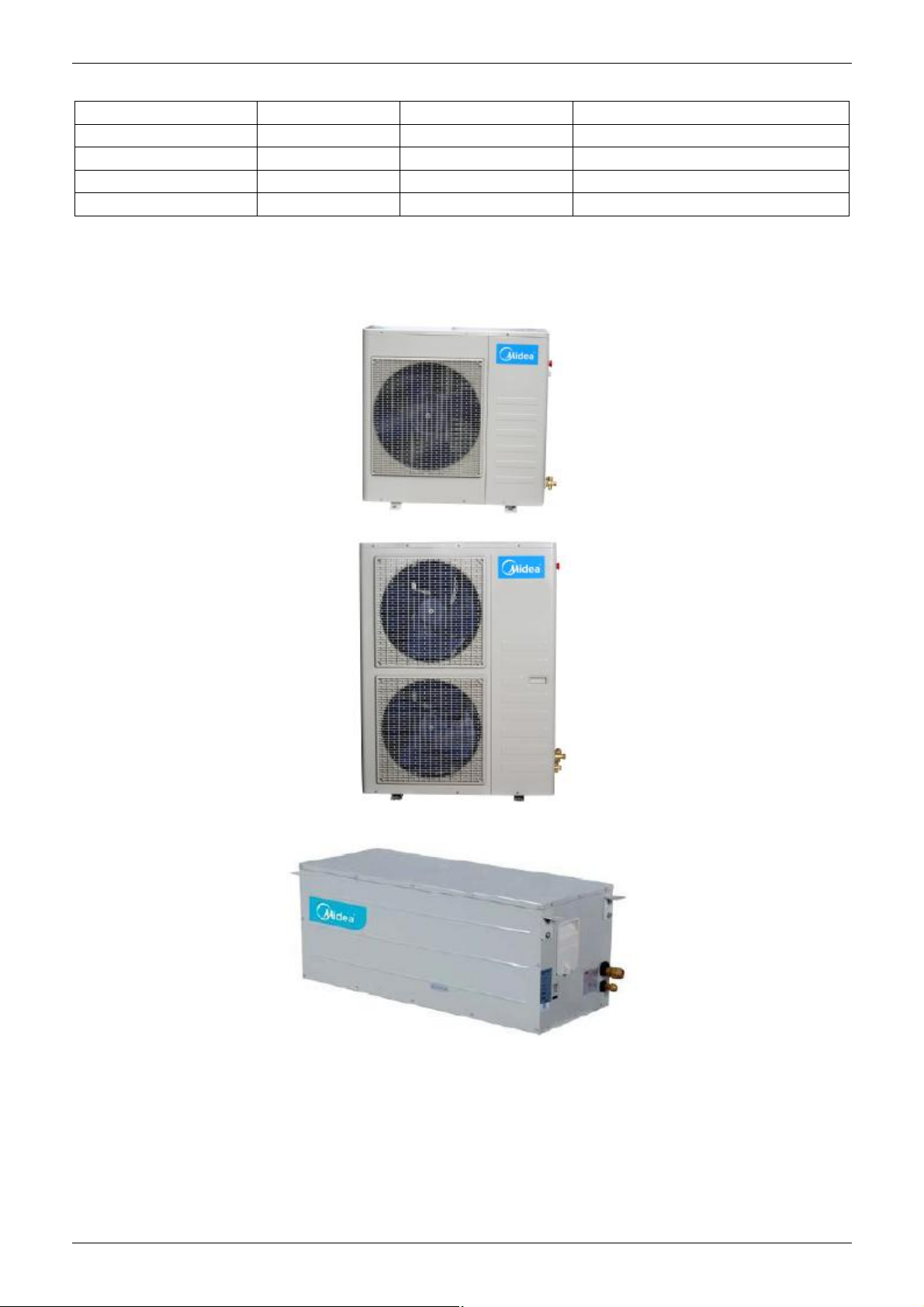
2. External Appearance
2.1 Outdoor Unit
MGA-D10/N1
MGA-D12/N1 MGA-D14/SN1 MGA-D16/SN1
2.2 Water Pump Box
2 General Information
Page 4

MCAC-UTSM-2008-11 Nomenclature
3. Nomenclature
Outdoor Unit:
- D 14 / S N1
Refrigerant
N1 R410A
Power Supply
S: 380-415V, 50Hz, 3ph
--: 220-240V, 50Hz, 1ph
Capacity(14kW)
D: Digital Scroll Type
Midea Chiller
4. Features
1. R410A environment friendly refrigerant.
2. Energy saving and reliable: Adopting Copeland digital scroll compressor, which can adjust the capacity
output and satisfy the capacity demands in different working conditions.
3. With remote on-off port and malfunction alarming output port on the main board.
4. Convenient and simple installation: With international popular split design, the pump box can be installed
inside the room and its outdoor unit is compact and light.
5. Flexible and convenient control: New wired controller with the Auto-restart functions of adjusting outlet
water temperature and power failure memory, etc..
6. The system doesn’t have EMC problem.
7. Built-in with emergency switch: Switch off the unit manually in any emergency case.
8. An AC contactor interface is added on the outdoor unit to connect with the auxiliary electric heater, which
can improve the capacity output in heating mode of low temperature.
9. One chiller can connect with more than 1 wired controller, it’s convenient to maintain and use.
General Information 3
Page 5

Outdoor Unit MCAC-UTSM-2008-11
Part 2
Outdoor Unit
1. Specifications ............................................................. 5
2. Dimensions ................................................................. 7
3. Service Space ............................................................. 8
4. Piping Diagram ........................................................... 9
5. Wiring Diagrams ....................................................... 10
6. Electric Characteristics ............................................ 12
7. Capacity Tables ........................................................ 12
8. Operation Limits ....................................................... 20
9. Hydraulic Performance ............................................ 21
10. Sound Levels .......................................................... 22
11. Exploded View ........................................................ 23
12. Troubleshooting ..................................................... 31
4 Outdoor Unit
Page 6
MCAC-UTSM-2008-11 Specifications
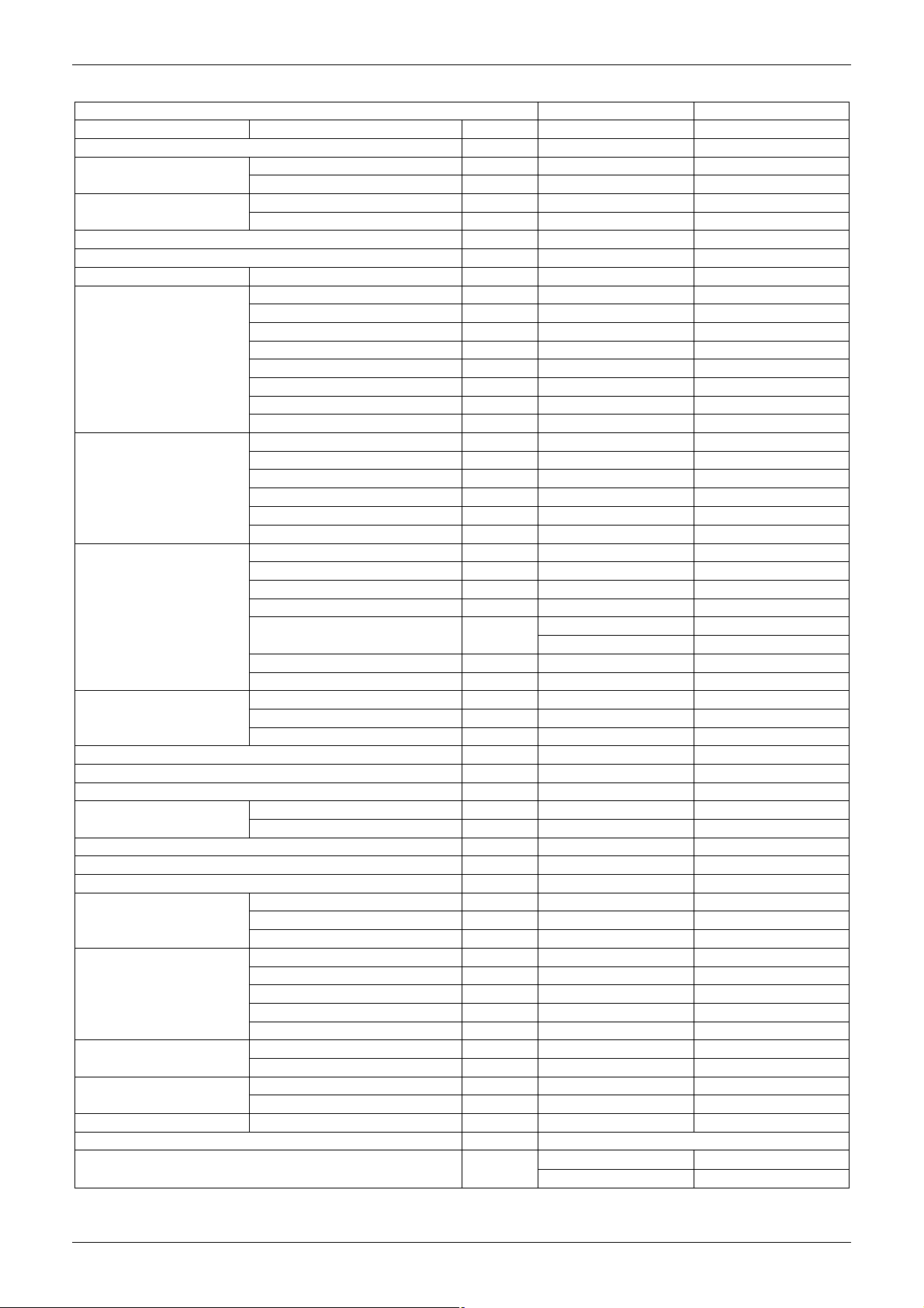
1. Specifications
Model MGA-D10/N1 MGA-D12/N1
Code 220090400050 220090400030
Power supply V-Ph-Hz
Cooling
Heating
Max. input consumption W 5430 5615
Max. input current A 27.4 28.2
Starting current A 124 130
Compressor
Outdoor fan motor
Outdoor coil
Water pump
Rated water flow m3/h 1.80 2.06
Max. air flow m3/h 4500 5800
Throttle Capillary Capillary
Noise level (sound
pressure)
Minimum water flow m3/h 0.9 1.03
The max. and min. water inlet pressure bar 5.0/0.5 5.0/0.5
The volume of expansion tank L 3 3
Outdoor unit
Water pump box
Refrigerant
Refrigerant pipe diameter
Pipe diameter Water inlet/outlet mm DN32 DN32
Control Wired controller KJR-08B/BE
Ambient temperature
Capacity kW 10 12
Input W 3912 3978
Capacity kW 13.6 14.3
Input W 4216 4164
Model ZPD61KCE-PFZ-532 ZPD61KCE-PFZ-532
Type Digital Scroll Digital Scroll
Brand Copeland Copeland
Rated current (RLA) A 31.4 31.4
Locked rotor Amp (LRA) A 147 147
Thermal protector Inner Inner
Capacitor uF 80uF/440V 80uF/440V
Refrigerant oil ml POE OIL, 1892 POE OIL, 1892
Model YDK250-6E YDK100-6A(×2)
Type AC motor AC motor
Brand Welling Welling
Input (Hi/Lo) W 307/194 185/120(×2)
Capacitor uF 10uF±5% 450V 5uF/450V
Speed (Hi/Lo) r/min 740/530 860/610
Number of rows 2 2
Tube pitch(a)x row pitch(b) mm 25.4×22 25.4×22
Fin spacing mm 1.7 1.5
Fin type Hydrophilic aluminium Hydrophilic aluminium
Tube outside dia. and type mm
Coil length x height x width mm 863×915×44 888×1220×44
Number of circuits 4 7
Type LDPB2-30(S) LDPB2-30(S)
Input W 420 420
Pumping head m 22 20
Outdoor unit dB(A) 57 60
Water pump box dB(A) 38.4 38.9
Dimension (W×H×D) mm 990×966×340 940×1250×340
Packing (W×H×D) mm 1120×1100×440 1058×1380×435
Net/ Gross weight kg 109/115 122/128
Model CE-SBX/N1-01 CE-SBX/N1-01A
Code 220095700030 220095700010
Dimension (W×H×D) mm 905×370×366 905×370×366
Packing (W×H×D) mm 1057×439×436 1057×439×436
Net/ Gross weight kg 52/57 54/59
Type R410A R410A
Charged volume g 2700 3600
Liquid side mm Φ9.5 Φ9.5
Gas side mm Φ19 Φ19
℃
220-240, 1, 50 220-240, 1, 50
Φ9.53 Φ9.53
inner grooved tube inner grooved tube
Cooling: 10℃~43℃ Cooling: 10℃~43℃
Heating: -15℃~24℃ Heating: -15℃~24℃
Outdoor Unit 5
Page 7
Specifications MCAC-UTSM-2008-11
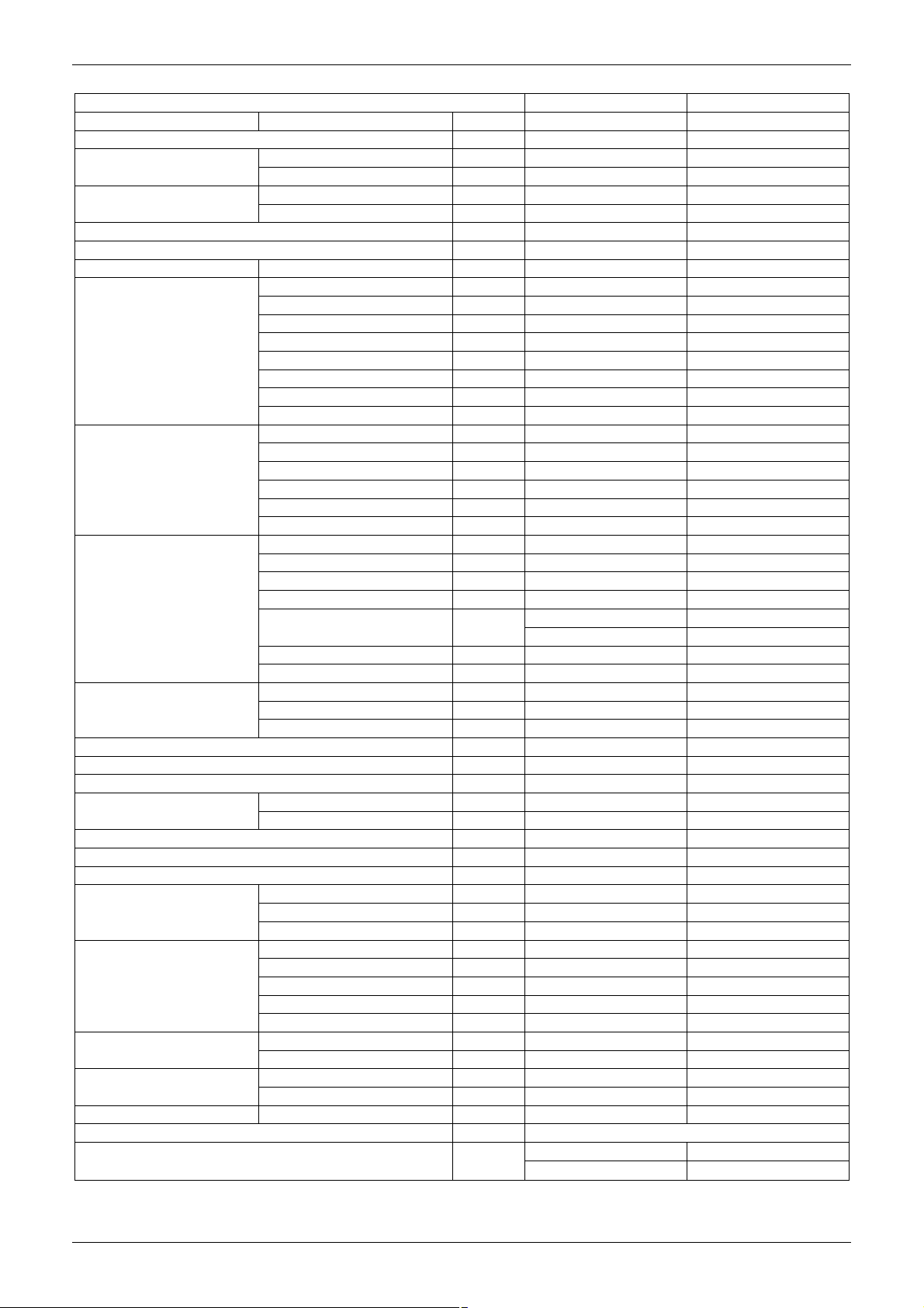
Model MGA-D14/SN1 MGA-D16/SN1
Code 220090400020 220090400040
Power supply V-Ph-Hz
Cooling
Heating
Max. input consumption W 6533 6573
Max. input current A 11.7 11.5
Starting current A 60 64
Compressor
Outdoor fan motor
Outdoor coil
Water pump
Rated water flow m3/h 2.4 2.58
Max. air flow m3/h 5600 5600
Throttle Capillary Capillary
Noise level (sound
pressure)
Minimum water flow m3/h 1.2 1.29
The max. and min. water inlet pressure bar 5.0/0.5 5.0/0.5
The volume of expansion tank L 3 3
Outdoor unit
Water pump box
Refrigerant
Refrigerant pipe diameter
Pipe diameter Water inlet/outlet mm DN32 DN32
Control Wired controller KJR-08B/BE
Ambient temperature ℃
Capacity kW 14 16
Input W 4453 4904
Capacity kW 16 17
Input W 4828 4943
Model ZPD72KCE-TFD-532 ZPD72KCE-TFD-532
Type Digital Scroll Digital Scroll
Brand Copeland Copeland
Rated current (RLA) A 9.8 9.8
Locked rotor Amp (LRA) A 82.4 82.4
Thermal protector Inner Inner
Capacitor uF / /
Refrigerant oil ml 3MAF POE, 1893 3MAF POE, 1893
Model YDK100-6A(×2) YDK100-6A(×2)
Type AC motor AC motor
Brand Welling Welling
Input (Hi/Lo) W 185/120(×2) 185/120(×2)
Capacitor uF 5uF/450V 5uF/450V
Speed (Hi/Lo) r/min 860/610 860/610
Number of rows 2.5 3
Tube pitch(a)x row pitch(b) mm 25.4×22 25.4×22
Fin spacing mm 1.5 1.5
Fin type Hydrophilic aluminium Hydrophilic aluminium
Tube outside dia. and type mm
Coil length x height x width mm 775×1220×66 875×1220×66
Number of circuits 12 8
Type LDPB2-30(S) LDPB2-30(S)
Input W 420 420
Pumping head m 18 17
Outdoor unit dB(A) 60 60
Water pump box dB(A) 41.2 37.8
Dimension (W×H×D) mm 940×1250×340 940×1250×340
Packing (W×H×D) mm 1058×1380×435 1058×1380×435
Net/ Gross weight kg 123/130 126/133
Model CE-SBX/SN1-01 CE-SBX/SN1-01A
Code 220095700000 220095700020
Dimension (W×H×D) mm 905×370×366 905×370×366
Packing (W×H×D) mm 1057×439×436 1057×439×436
Net/ Gross weight kg 54/59 55/60
Type R410A R410A
Charged volume g 4100 4400
Liquid side mm Φ9.5 Φ9.5
Gas side mm Φ19 Φ19
380-415, 3, 50 380-415, 3, 50
Φ9.53 Φ9.53
inner grooved tube inner grooved tube
Cooling: 10℃~43℃ Cooling: 10℃~43℃
Heating: -15℃~24℃ Heating: -15℃~24℃
6 Outdoor Unit
Page 8
MCAC-UTSM-2008-11 Dimensions
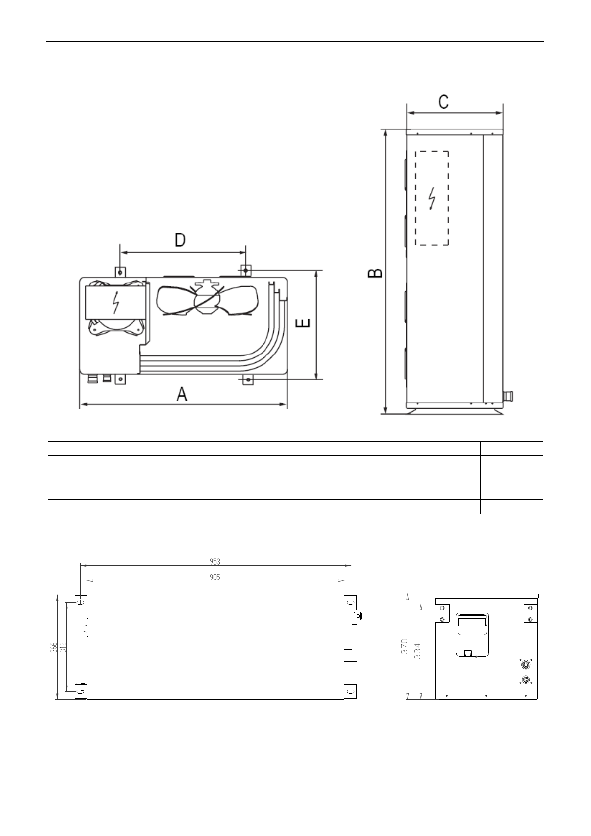
2. Dimensions
2.1 Outdoor Unit
Dimensions A B C D E
MGA-D10/N1 990 966 340 624 366
MGA-D12/N1 940 1250 340 600 376
MGA-D14/SN1 940 1250 340 600 376
MGA-D16/SN1 940 1250 340 600 376
2.2 Water Pump Box
Unit: mm
Outdoor Unit 7
Page 9

Service Space MCAC-UTSM-2008-11
3. Service Space
8 Outdoor Unit
Page 10
MCAC-UTSM-2008-11 Piping Diagram
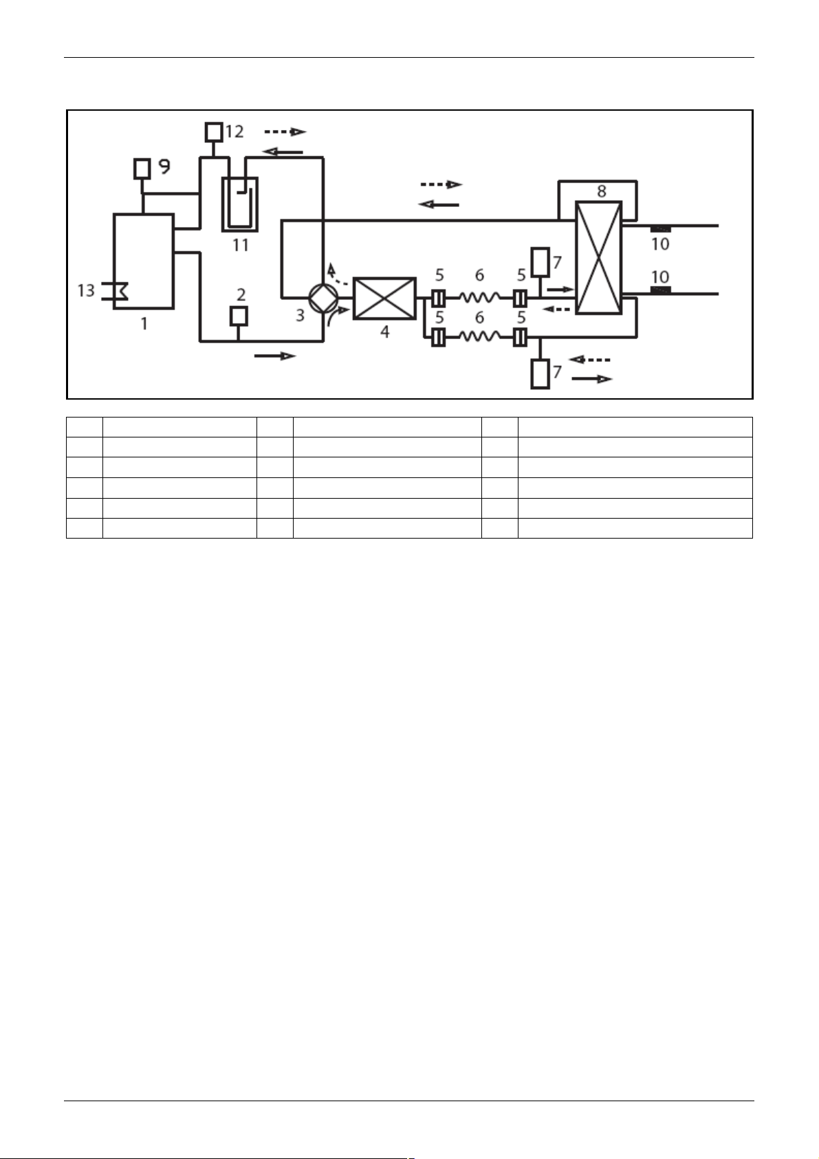
4. Piping Diagram
Remark:
No Name No Name No Name
1 Compressor 6 Capillary 11 Liquid receiver
2 High pressure switch 7 Liquid receiver 12 Low pressure switch
3 4 -way valve 8 Plate heat exchanger 13 Crank heater
4 Condenser 9 PWM valve
5 Filter 10 Water temperature sensor
Outdoor Unit 9
Page 11
Wiring Diagrams MCAC-UTSM-2008-11
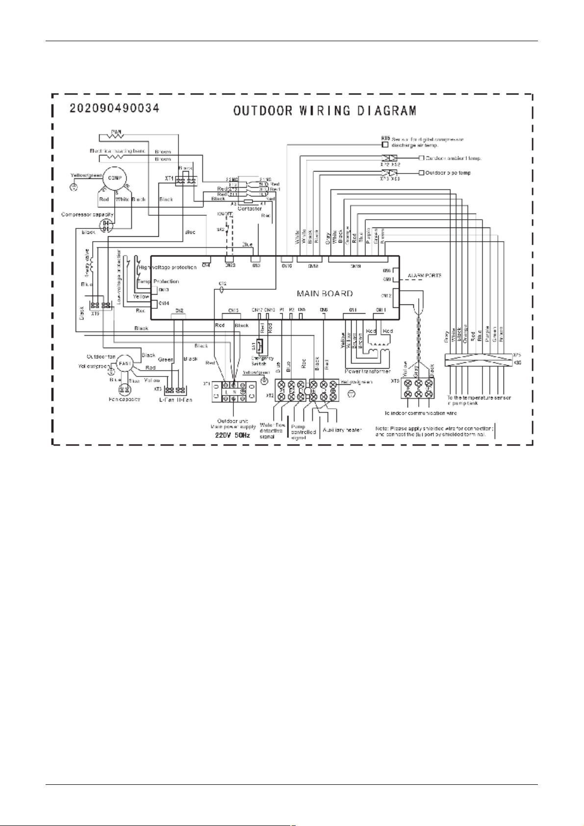
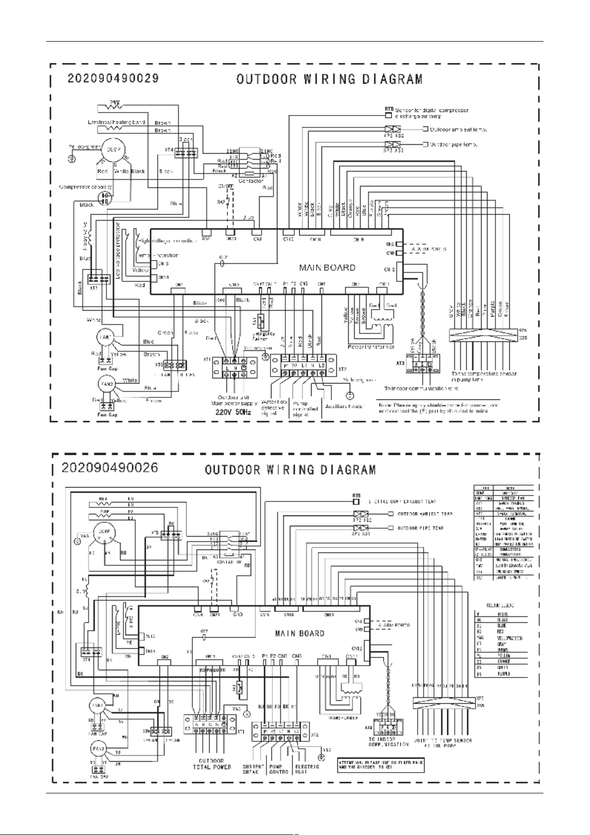
5. Wiring Diagrams
5.1 MGA-D10/N1
10 Outdoor Unit
Page 12
MCAC-UTSM-2008-11 Wiring Diagrams
5.2 MGA-D12/N1
5.3 MGA-D14/SN1 MGA-D16/SN1
Outdoor Unit 11
Page 13
Electric Characteristics MCAC-UTSM-2008-11
3
3
3
3
3
6. Electric Characteristics
Rated values Fuses
Mod.
kW
10 220-240-1-50 5.0 23.2 147 0.3 1.4 0.5 2.2 5.8 26.8 7.54 34.8 45A
12 220-240-1-50 5.0 23.2 147 0.37 1.6 0.5 2.2 5.8 27 7.63 35.1 45A
14 380-415-3-50 5.75 9.8 82.4 0.37 1.6 0.5 2.2 6.62 13.6 8.6 17.7 25A
16 380-415-3-50 5.75 9.8 82.4 0.37 1.6 0.5 2.2 6.62 13.6 8.6 17.7 25A
Remark:
F.L.I. Power input
F.L.A. Current input
L.R.A. Compressor start-up current
(1) Outside air temperature 35℃-Water temperature at evaporator 12/7℃
(2) Values refer to the lower rated voltage(50Hz). These values are used to judge the protection switch size and the thickness
Electrical
Power supply
(V-ph-Hz)
of the power supply cable.
Compressors Fan/fans Pump Total
F.L.I. F.L.A. L.R.A. F.L.I. F.L.A. F.L.I. F.L.A. F.L.I. F.L.A. F.L.I. F.L.A.
(kW) (A) (A) (kW) (A) (kW) (A) (kW) (A) (kW) (A)
Max.
values(2)
Glass
5×20mm
250V
Fuse 1
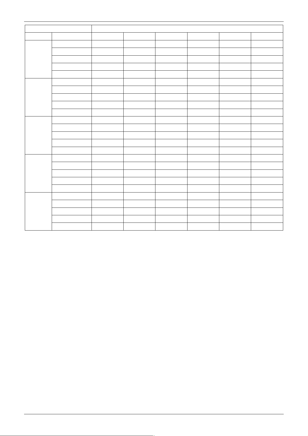
7. Capacity Tables
7.1 Cooling capacity
Model MGA-D10/N1
Ta. (°C) Tw (°C)
Pf (kW)
Pa (kW)
25
30
35
40
43
Remark:
Ta: outside air temperature (°C)
Tw : evaporator water outlet temperature (°C)
Pat (kW)
Qev (m
△Pev (kPa)
Pf (kW)
Pa (kW)
Pat (kW)
Qev (m
△Pev (kPa)
Pf (kW)
Pa (kW)
Pat (kW)
Qev (m
△Pev (kPa)
Pf (kW)
Pa (kW)
Pat (kW)
Qev (m
△Pev (kPa)
Pf (kW)
Pa (kW)
Pat (kW)
Qev (m
△Pev (kPa)
/h)
/h)
/h)
/h)
/h)
Pf: cooling capacity (kW)
Pa: compressor power input (kW)
Pat: total power input (kW)
Qev: evaporator water flow (m3/h)
Pev: evaporator△ pressure drop (kPa)
5 6 7 8 9 10
10.9 11.2 11.5 11.8 12.1 12.4
3.3 3.3 3.4 3.4 3.4 3.5
4.1 4.1 4.2 4.2 4.2 4.3
1.9 1.9 2.0 2.0 2.1 2.2
47.3 47.6 50.0 50.3 54.0 57.0
10.4 10.8 11.1 11.5 11.8 12.1
2.9 2.9 3.0 3.1 3.1 3.1
3.4 3.4 3.5 3.6 3.6 3.6
1.8 1.8 1.9 2.0 2.0 2.0
44.7 45.6 47.7 49.8 50.4 50.9
9.9 10.2 10.5 10.7 11.0 11.3
3.3 3.3 3.4 3.4 3.5 3.5
3.8 3.8 3.9 3.9 4.0 4.0
1.7 1.7 1.8 1.9 1.9 2.0
40.5 41.3 45.0 48.0 48.6 51.0
9.4 9.7 10.0 10.3 10.6 11.0
3.6 3.6 3.7 3.7 3.8 3.8
4.1 4.1 4.2 4.2 4.3 4.3
1.6 1.6 1.7 1.7 1.8 1.8
36.0 36.6 40.8 41.4 45.5 45.8
9.0 9.3 9.5 9.8 10.0 10.3
3.8 3.8 3.9 3.9 4.0 4.0
4.3 4.3 4.4 4.4 4.5 4.5
1.5 1.6 1.6 1.7 1.7 1.8
31.5 35.7 36.6 40.5 41.3 46.5
12 Outdoor Unit
Page 14
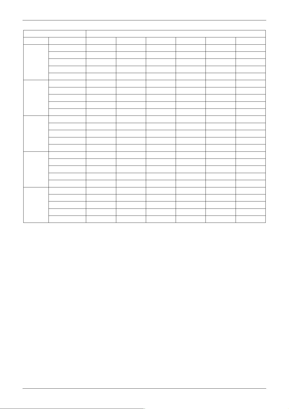
MCAC-UTSM-2008-11 Capacity Tables
3
3
3
3
3
Model MGA-D12/N1
Ta. (°C) Tw (°C)
Pf (kW)
Pa (kW)
25
Pat (kW)
Qev (m
△Pev (kPa)
Pf (kW)
Pa (kW)
30
Pat (kW)
Qev (m
△Pev (kPa)
Pf (kW)
Pa (kW)
35
Pat (kW)
Qev (m
△Pev (kPa)
Pf (kW)
Pa (kW)
40
Pat (kW)
Qev (m
△Pev (kPa)
Pf (kW)
Pa (kW)
43
Pat (kW)
Qev (m
△Pev (kPa)
/h)
/h)
/h)
/h)
/h)
5 6 7 8 9 10
12.4 12.7 13.0 13.3 13.6 13.9
3.5 3.5 3.5 3.6 3.6 3.6
4.1 4.1 4.1 4.2 4.2 4.2
2.2 2.2 2.3 2.3 2.3 2.4
46.6 47.8 49.6 51.8 54.6 60.0
11.9 12.2 12.5 12.8 13.1 13.4
3.8 3.8 3.8 3.9 3.9 3.9
4.4 4.4 4.4 4.5 4.5 4.5
2.0 2.1 2.1 2.2 2.2 2.3
37.0 37.1 40.6 43.2 46.1 48.0
11.4 11.7 12.0 12.3 12.6 12.9
4.2 4.2 4.2 4.3 4.3 4.3
4.8 4.8 4.8 4.9 4.9 4.9
2.0 2.0 2.1 2.1 2.2 2.2
33.8 37.1 40.6 43.2 46.1 48.0
10.9 11.2 11.5 11.8 12.1 12.4
4.5 4.5 4.5 4.6 4.6 4.6
5.1 5.1 5.1 5.2 5.2 5.2
1.9 2.0 2.0 2.0 2.1 2.1
32.3 35.0 36.3 38.4 41.0 45.1
10.5 10.8 11.1 11.4 11.7 12.0
4.7 4.7 4.7 4.8 4.8 4.8
5.3 5.3 5.3 5.4 5.4 5.4
1.8 1.9 1.9 2.0 2.0 2.0
28.0 30.1 33.8 37.4 38.6 40.5
Remark:
Ta: outside air temperature (°C )
Tw : evaporator water outlet temperature (°C)
Pf: cooling capacity (kW)
Pa: compressor power input (kW)
Pat: total power input (kW)
Qev: evaporator water flow (m3/h)
Pev: evaporator△ pressure drop (kPa)
Outdoor Unit 13
Page 15
Capacity Tables MCAC-UTSM-2008-11
Model MGA-D14/SN1
Ta. (°C) Tw (°C) 5 6 7 8 9 10
Pf (kW) 14.8 15.1 15.4 15.7 16.1 16.4
Pa (kW) 3.6 3.6 3.6 3.7 3.7 3.7
25
30
35
40
43
Remark:
Ta: outside air temperature (°C )
Tw : evaporator water outlet temperature (°C)
Pf: cooling capacity (kW)
Pa: compressor power input (kW)
Pat: total power input (kW)
Qev: evaporator water flow (m3/h)
Pev: evaporator△ pressure drop (kPa)
Pat (kW) 4.1 4.1 4.1 4.2 4.2 4.2
Qev (m3/h) 2.6 2.6 2.7 2.7 2.8 2.8
△Pev (kPa) 49.3 50.0 51.7 53.0 56.1 57.8
Pf (kW) 14.1 14.4 14.7 15.0 15.3 15.6
Pa (kW) 4.1 4.1 4.1 4.2 4.2 4.2
Pat (kW) 4.6 4.6 4.7 4.7 4.7 4.7
Qev (m3/h) 2.4 2.5 2.5 2.6 2.6 2.7
△Pev (kPa)
Pf (kW) 13.4 13.7 14.0 14.3 14.6 14.9
Pa (kW) 4.6 4.6 4.6 4.7 4.7 4.7
Pat (kW) 5.1 5.1 5.1 5.2 5.2 5.2
Qev (m3/h) 2.3 2.4 2.4 2.5 2.5 2.5
△Pev (kPa) 40.8 43.5 44.2 46.9 47.8 48.3
Pf (kW) 12.5 12.8 13.1 13.4 13.7 14.0
Pa (kW) 5.1 5.1 5.1 5.2 5.2 5.2
Pat (kW) 5.6 5.6 5.6 5.7 5.7 5.7
Qev (m3/h) 2.2 2.2 2.3 2.3 2.4 2.4
△Pev (kPa) 33.3 34.5 36.7 39.8 43.7 44.9
Pf (kW) 12.0 12.3 12.6 12.9 13.2 13.5
Pa (kW) 5.5 5.5 5.5 5.6 5.6 5.6
Pat (kW) 6.0 6.0 6.0 6.1 6.1 6.1
Qev (m3/h) 2.1 2.1 2.2 2.2 2.3 2.3
△Pev (kPa) 30.6 32.5 35.2 36.2 39.1 40.5
43.9 47.9 48.3 49.1 50.2 52.7
14 Outdoor Unit
Page 16
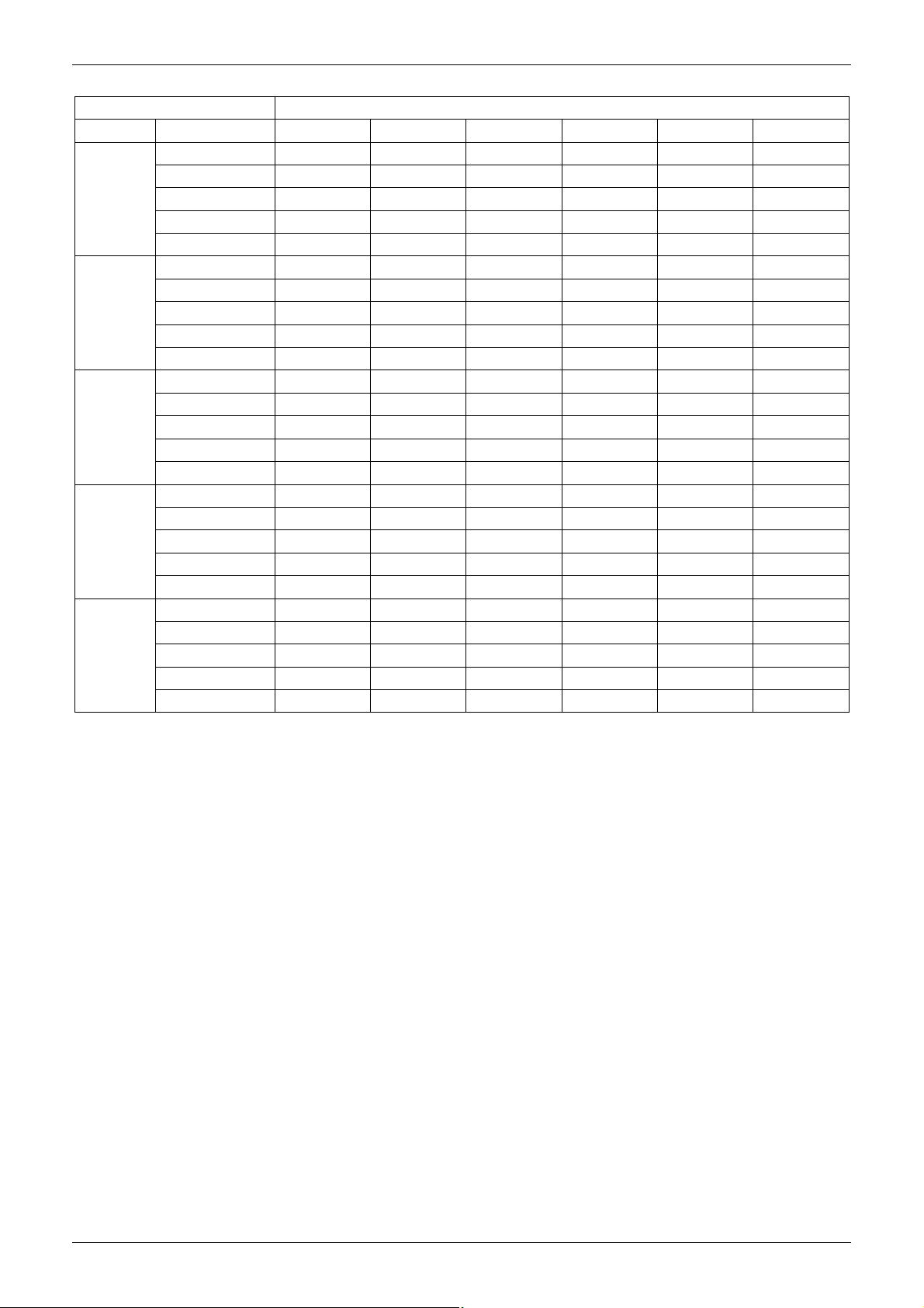
MCAC-UTSM-2008-11 Capacity Tables
3
3
3
3
3
Model MGA-D16/SN1
Ta. (°C)
Tw (°C)
Pf (kW)
Pa (kW)
25
Pat (kW)
Qev (m
/h)
△Pev (kPa)
Pf (kW)
Pa (kW)
30
Pat (kW)
Qev (m
/h)
△Pev (kPa)
Pf (kW)
Pa (kW)
35
Pat (kW)
Qev (m
/h)
△Pev (kPa)
Pf (kW)
Pa (kW)
40
Pat (kW)
Qev (m
/h)
△Pev (kPa)
Pf (kW)
Pa (kW)
43
Pat (kW)
Qev (m
/h)
△Pev (kPa)
Remark:
Ta: outside air temperature (°C )
Tw : evaporator water outlet temperature (°C)
Pf: cooling capacity (kW)
Pa: compressor power input (kW)
Pat: total power input (kW)
Qev: evaporator water flow (m3/h)
Pev: evaporator△ pressure drop (kPa)
5 6 7 8 9 10
15.5 15.7 16.0 16.3 16.5 16.8
3.9 3.9 3.9 4.0 4.0 4.0
4.7 4.7 4.7 4.8 4.8 4.8
2.7 2.7 2.8 2.8 2.9 2.9
54.9 57.6 59.4 62.1 65.2 67.7
14.9 15.2 15.5 15.8 16.1 16.4
4.4 4.4 4.4 4.5 4.5 4.5
5.2 5.2 5.2 5.4 5.4 5.4
2.6 2.6 2.7 2.7 2.8 2.8
51.0 52.9 50.9 54.7 59.9 63.0
14.4 14.7 15.0 15.3 15.6 15.9
4.9 4.9 4.9 5.0 5.0 5.0
5.7 5.7 5.7 5.8 5.8 5.8
2.6 2.6 2.7 2.7 2.8 2.8
50.8 53.1 55.8 58.1 61.2 63.2
13.9 14.2 14.5 14.8 15.1 15.2
5.3 5.3 5.3 5.4 5.4 5.4
6.1 6.1 6.1 6.2 6.2 6.2
2.5 2.5 2.6 2.6 2.7 2.7
46.8 49.1 51.5 53.1 55.8 59.4
13.5 13.8 14.1 14.4 14.7 14.8
5.7 5.7 5.7 5.8 5.8 5.8
6.5 6.5 6.5 6.6 6.6 6.6
2.4 2.4 2.5 2.5 2.6 2.6
41.4 44.3 47.0 49.1 51.5 59.4
Outdoor Unit 15
Page 17
Capacity Tables MCAC-UTSM-2008-11
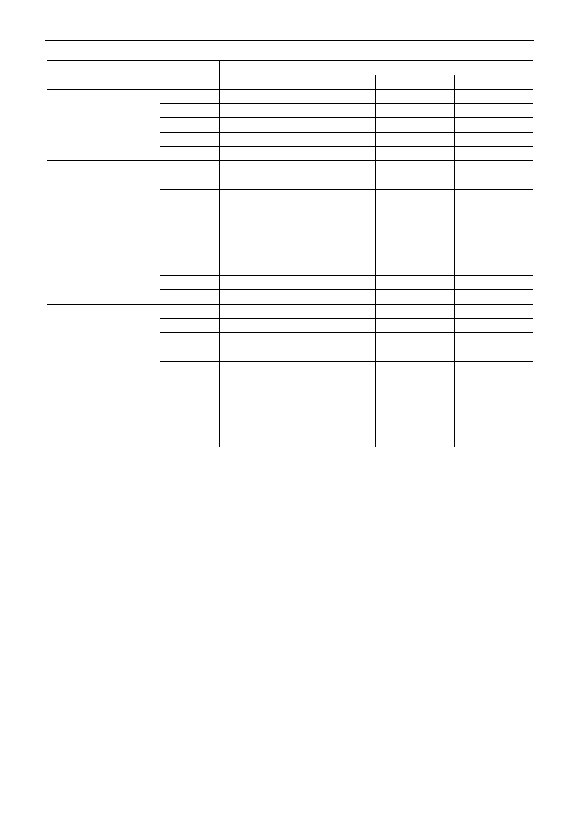
7.2 Heating capacity
Model MGA-D10/N1
Ta. U.R.87% (°C) Tw (°C) 35 40 45 50
Pt (kW) 8.3 8.3 8.3 —
Pa (kW) 3.6 3.9 4.2 —
-5
0
7
10
15
Remark:
Ta: outside air temperature (°C )
Tw : evaporator water outlet temperature (°C)
Pt: heating capacity (kW)
Pa: compressor power input (kW)
Pat: total power input (kW)
Qc: condenser water flow (m3/h)
ΔPc: evaporator pressure drop (kPa)
— : conditions outside of operating limits
Pat (kW) 4.4 4.7 5.0 —
Qc (m3/h) 1.5 1.5 1.5 —
Pc (kPa)△ 29.4 28.4 27.0 —
Pt (kW) 9.4 9.4 9.4 9.2
Pa (kW) 3.7 4.0 4.3 4.5
Pat (kW) 4.5 4.8 5.1 5.3
Qc (m3/h) 1.8 1.8 1.8 1.8
Pc (kPa)△ 27.5 25.6 24.8 23.2
Pt (kW) 13.2 13.1 13.0 12.9
Pa (kW) 3.8 4.1 4.4 4.7
Pat (kW) 4.6 4.9 5.2 5.5
Qc (m3/h) 2.2 2.2 2.2 2.2
Pc (kPa)△ 37.2 35.8 34.5 33.1
Pt (kW) 12.3 12.2 12.1 12.0
Pa (kW) 3.9 4.2 4.5 4.8
Pat (kW) 4.7 5.0 5.3 5.1
Qc (m3/h) 2.3 2.3 2.3 2.3
Pc (kPa)△ 40.5 40.0 39.2 38.8
Pt (kW) 13.8 13.7 13.6 13.5
Pa (kW) 4.0 4.3 4.6 4.9
Pat (kW) 4.8 5.1 5.4 5.7
Qc (m3/h) 2.4 2.4 2.3 2.3
Pc (kPa)△ 45.8 45.1 43.6 42.9
16 Outdoor Unit
Page 18
MCAC-UTSM-2008-11 Capacity Tables
Model MGA-D12/N1
Ta. U.R.87% (°C) Tw (°C)
Pt (kW) 11.0 10.9 10.8 —
Pa (kW) 3.7 4.0 4.3 —
-5
0
7
10
15
Remark:
Ta: outside air temperature (°C )
Tw : evaporator water outlet temperature (°C)
Pt: heating capacity (kW)
Pa: compressor power input (kW)
Pat: total power input (kW)
Qc: condenser water flow (m3/h)
ΔPc: evaporator pressure drop (kPa)
— : conditions outside of operating limits
Pat (kW) 4.5 4.8 5.1 —
Qc (m3/h) 1.7 1.7 1.7 —
Pc (kPa)△
Pt (kW) 12.2 12.1 12.0 11.9
Pa (kW) 3.8 4.1 4.4 4.6
Pat (kW) 4.6 4.9 5.2 5.4
Qc (m3/h) 2.0 2.0 2.0 2.0
Pc (kPa)△
Pt (kW) 14.2 14.1 14.0 13.9
Pa (kW) 3.9 4.2 4.5 4.8
Pat (kW) 4.7 5.0 5.3 5.6
Qc (m3/h) 2.4 2.4 2.4 2.4
Pc (kPa)△
Pt (kW) 15.2 15.1 15.0 14.9
Pa (kW) 4.0 4.3 4.6 4.9
Pat (kW) 4.8 5.1 5.4 5.7
Qc (m3/h) 2.5 2.5 2.5 2.5
Pc (kPa)△
Pt (kW) 16.7 16.6 16.5 16.4
Pa (kW) 4.1 4.4 4.7 5.0
Pat (kW) 4.9 5.2 5.5 5.8
Qc (m3/h) 2.8 2.8 2.8 2.8
Pc (kPa)△
35 40 45 50
41.6 41.0 40.3 —
33.0 32.6 32.1 31.8
44.0 43.6 43.1 42.8
38.0 37.6 37.2 37.0
45.0 44.8 44.6 44.2
Outdoor Unit 17
Page 19

Capacity Tables MCAC-UTSM-2008-11
Model MGA-D14/SN1
Ta. U.R.87% (°C) Tw (°C)
Pt (kW) 10.4 10.5 10.6 —
Pa (kW) 4.0 4.4 4.9 —
-5
0
7
10
15
Remark:
Ta: outside air temperature (°C )
Tw : evaporator water outlet temperature (°C)
Pt: heating capacity (kW)
Pa: compressor power input (kW)
Pat: total power input (kW)
Qc: condenser water flow (m3/h)
ΔPc: evaporator pressure drop (kPa)
— : conditions outside of operating limits
Pat (kW) 4.8 5.2 5.7 —
Qc (m3/h) 1.9 1.9 1.9 —
Pc (kPa)△
Pt (kW) 13.1 13.0 13.0 12.9
Pa (kW) 4.0 4.4 4.9 5.4
Pat (kW) 4.8 5.2 5.7 6.1
Qc (m3/h) 2.3 2.3 2.3 2.3
Pc (kPa)△
Pt (kW) 16.2 16.1 16.0 15.9
Pa (kW) 4.1 4.5 5.0 5.5
Pat (kW) 4.9 5.3 5.8 6.3
Qc (m3/h) 2.8 2.8 2.8 2.8
Pc (kPa)△
Pt (kW) 17.6 17.5 17.4 17.4
Pa (kW) 4.2 4.6 5.1 5.6
Pat (kW) 5.0 5.4 5.9 6.4
Qc (m3/h) 3.1 3.1 3.1 3.1
Pc (kPa)△
Pt (kW) 19.8 19.7 19.6 19.4
Pa (kW) 4.3 4.7 5.2 5.7
Pat (kW) 5.1 5.5 6.0 6.5
Qc (m3/h) 3.5 3.5 3.5 3.5
Pc (kPa)△
35 40 45 50
25.8 27.2 27.0 —
21.1 21.1 21.0 21.0
31.2 31.1 31.0 31.0
36.4 36.2 36.0 35.9
45.4 45.2 45.0 44.9
18 Outdoor Unit
Page 20

MCAC-UTSM-2008-11 Capacity Tables
Model MGA-D16/SN1
Ta. U.R.87% (°C) Tw (°C)
Pt (kW) 11.5 11.4 11.3 —
Pa (kW) 4.1 4.5 5.0 —
-5
0
7
10
15
Remark:
Ta: outside air temperature (°C )
Tw : evaporator water outlet temperature (°C)
Pt: heating capacity (kW)
Pa: compressor power input (kW)
Pat: total power input (kW)
Qc: condenser water flow (m3/h)
ΔPc: evaporator pressure drop (kPa)
— : conditions outside of operating limits
Pat (kW) 4.9 5.3 5.8 —
Qc (m3/h) 2.0 2.0 2.0 —
Pc (kPa)△
Pt (kW) 14.2 14.1 14.0 13.9
Pa (kW) 4.2 4.6 5.1 5.6
Pat (kW) 5.0 5.4 5.1 5.6
Qc (m3/h) 5.0 5.4 5.9 6.4
Pc (kPa)△
Pt (kW) 17.2 17.1 17.0 16.9
Pa (kW) 4.3 4.7 5.2 5.7
Pat (kW) 5.1 5.5 6.0 6.5
Qc (m3/h) 2.9 2.9 2.9 2.9
Pc (kPa)△
Pt (kW) 18.7 18.6 18.5 18.4
Pa (kW) 4.4 4.8 5.3 5.8
Pat (kW) 5.2 5.6 6.1 6.6
Qc (m3/h) 3.2 3.2 3.2 3.2
Pc (kPa)△
Pt (kW) 21.0 20.9 20.8 20.7
Pa (kW) 4.5 4.9 5.4 5.9
Pat (kW) 5.3 5.7 6.2 6.7
Qc (m3/h) 3.6 3.6 3.6 3.6
Pc (kPa)△
35 40 45 50
25.0 25.0 24.8 —
20.2 20.1 20.0 19.9
30.2 30.1 30.0 30.0
35.4 35.2 35.0 34.8
46.2 45.6 45.0 44.4
Outdoor Unit 19
Page 21

Operation Limits MCAC-UTSM-2008-11
8. Operation Limits
Cooling operation
Heating operation
Outdoor temperature: 10℃~43℃
Water temperature: 4℃-20℃
Outdoor temperature: 4℃~24℃ (-15℃~24 , when charge enough antifreeze)℃
Water temperature: 30℃-50℃
8.1 Ethylene Glycol Solutions
Water and ethylene glycol solutions used as a thermal vector in the place of water reduce the performance
of the unit. Multiply the performance figures by the values given in the following table.
Freezing point (°C)
0 -5 -10 -15 -20 -25
Percentage of ethylene glycol in weight
0 12% 20% 28% 35% 40%
cPf 1 0.98 0.97 0.965 0.96 0.955
cQ 1 1.02 1.04 1.075 1.11 1.14
cdp 1 1.07 1.11 1.18 1.22 1.24
cPf: correction factor refrigerating capacity
cQ: correction factor flow rate
cdp: correction factor pressure drop
Note:
1. During winter leaving the unit unused, please drain water out completely from unit if no antifreeze were
charged into pipeline, or keep power on (at standby or off status) and ensure that water is contained
inside of unit.
2. When ambient temperature is lower than 5, running cooling mode must be charged antifreeze. Refer to ℃
upper parameters for the charged volume.
8.2 Fouling Factors
The performance data given refer to conditions with clean evaporator plates (fouling factor=1). For different
fouling factors, multiply the figures in the performance tables by the coefficient given in the following table.
Fouling factors Evaporator
(m2°C/W) f1 fk1 fx1
-5
4.4×10
0.86×10⁻⁴ 0.96 0.99 0.99
1.72×10⁻⁴ 0.93 0.98 0.98
f1 capacity correction factor
fk1 compressor power input correction factor
fx1 total power input correction factor
- - -
20 Outdoor Unit
Page 22

MCAC-UTSM-2008-11 Hydraulic Performance
8.3 Quantity of Water in Installation
Model MGA-D10/N1 MGA-D12/N1 MGA-D14/SN1 MGA-D16/SN1
Minimum water volume (L) 43 50 60 68
If the total water volume in the system is less than the value in the table above, the additional water tank is
necessary in order to avoid the compressor On/Off frequency.
The minimum size of the water tank is calculated as:
Size of additional water tank(L)=Minimum water volume (L) –Actual water volume(L)
9. Hydraulic Performance
9.1 Pump head curves(*)
Note:
(*) To obtain the useful head of the installation, subtract the pressure drop of the plate heat exchanger.
9.2 Heat exchanger pressure drop (water side)
Model
10kW
Water flow
Pressure drop kPa 26 29 33 37 42 46 50
m 3 / h 0.8 1.0 1.2 1.4 1.6 1.8 2.0
l/sec 0.222 0.278 0.333 0.389 0.444 0.500 0.556
Model Water flow
12 kW
14 kW kPa 28 31 36 40 43 46 50 54
16 kW kPa 26 29 32 37 41 45 49 52
Pressure drop
m 3 / h 1.2 1.4 1.6 1.8 2.0 2.2 2.4 2.6
l/sec 0.333 0.389 0.444 0.500 0.556 0.611 0.667 0.722
kPa 35 39 44 47 50 53 58
Outdoor Unit 21
Page 23

Sound Levels MCAC-UTSM-2008-11
10. Sound Levels
10kW 12/14/16kW
Microphone
H
1.0m
Note: H= 0.5 × height of outdoor unit Note: The point A is in the middle of the whole outdoor
panel.
Model Noise level dB(A)
MGA-D10/N1 57
MGA-D12/N1 60
MGA-D14/SN1 60
MGA-D16/SN1 60
22 Outdoor Unit
Page 24

MCAC-UTSM-2008-11 Exploded View
11. Exploded View
11.1 MGA-D10/N1
Matched water pump box- CE-SBX/N1-01
Outdoor Unit 23
Page 25

Exploded View MCAC-UTSM-2008-11
MGA
-
D10/N1
No.
Part Name
Quantity
No. Part Name
Quantity
CE-SBX/N1
-
01
No. Part Name
Quan
tity No. Part Name
Quantity
1 Top cover ass'y 1 7.25 Wire joint 1
2 Rear Supporter 1 7.26 Compressor capacitor 1
3 Condenser ass'y 1 7.27 Wire clamp 1
4 High pressure valve ass'y 1 8 Separator 1
4.1 Low pressure valve 1 9 Big handle 1
5 Partition board ass'y 1 10 Front right clapboard ass'y 1
6 Rear right clapboard ass'y 1 11 Valve plate 1
7 E-part box ass'y 1 12 Compressor 1
7.1 485 communication wire 1 13 Branch pipe ass'y 1
7.2 Transformer 1 14 Compressor electric heater 1
7.3 Cable 1 15 Base ass'y 1
7.4 Damp 1 16 Suction pipe ass'y 1
7.5 Electric installation board 1 16.1 Pressure controller 1
7.6 Capacitor 1 17 Solenoid valve ass'y 1
7.7 Capacitor installation board 1 17.1 Pressure-relief-valve 1
7.8 Capacitor clamp 1 18 4-way valve ass'y 1
7.9 Capacitor clamp 1 18.1 Solenoid 1
7.10 Wire clamp 1 18.2 4-way valve 1
7.11 Terminal board 1 18.3 Low pressure valve 1
7.12 Urgency switch 1 18.4 Pressure controller 1
7.13 AC contactor 1 19 Axial flow fan 1
7.14 Wire joint ass'y 1 20 Motor 1
7.15 Wire joint 1 21 Motor bracket ass'y 1
7.16 Wire joint 1 22 Grille 1
7.17 Wire joint 3 23 Front panel 1
7.18 Wire joint 1 24 Wire controller 1
7.19 Wire joint 1 25 Left holder 1
7.20 Surge suppresser 1 26 Temp sensor 1
7.21 Caution label 1 27 Pipe temp sensor ass'y 1
7.22 Power supply wire 1 28 Discharge temp sensor ass'y 1
7.23 Main control board ass'y 1 29 Discharge temp sensor 1
7.24 Outdoor communication cable 1
Water pump box
1 Up covering plate 1 18.2 Branch pipe 2
2 Water-inlet pipe ass'y 1 18.3 Screw 1
2.1 Pipe joint 1 18.4 Elbow pipe 1
2.2 Elbow pipe 1 18.5 Inner joint 1
3 Hook 4 19 Water charge valve 1
4 Pipe clamp I 1 20 Rear clapboard 2
5 Front clapboard 1 21 Input pipe ass'y 1
6 Pipe clamp II 1 21.1 Pipe joint 1
7 Right cover ass'y 1 21.2 Copper nut 1
8 Capacitor clamp 1 22 Water-outlet pipe ass'y 1
9 Water-inlet pipe supporter 2 22.1 Water-outlet pipe ass'y I 1
10 Input pipe ass'y 1 22.2 Drain pipe adapter 1
10.1 Accumulator tank 1 23 Water-outlet pipe ass'y II 1
11 Water-inlet pipe ass'y 1 23.1 Elbow pipe 1
11.1 outer joint 1 23.2 Water-outlet pipe II 1
11.2 Pipe joint 1 23.3 Pipe joint 1
11.3 Water-inlet pipe ass'y I 1 24 Pump 1
12 Base 1 25 Water-outlet pipe ass'y I 1
13 Expansion vessel 1 25.1 Pipe joint 3
14 Heat-exchanger plate ass'y 1 25.2 Elbow pipe 2
14.1 Plate Heat-exchanger 1 26 Installation bracket 1
14.2 Elbow pipe 1 27 Big handle 1
14.3 Pipe joint 1 28 Left clapboard ass'y 1
14.4 Pipe hoop 1 29 Safety valve 1
14.5 Pipe joint 1 30 Discharge valve 1
14.6 Copper nut 1 31 Water-outlet pipe III 1
15 Target flow-volume controller 1 32 Input pipe ass'y 1
16 Clamp 1 32.1 Accumulator tank 1
17 Water charge pipe 1 33 Temp. sensor ass'y 1
18 Water-inlet pipe ass'y II 1 34 Wire joint, 5p 1
18.1 Pipe joint 3
24 Outdoor Unit
Page 26

MCAC-UTSM-2008-11 Exploded View
11.2 MGA-D12/N1
Matched water pump box- CE-SBX/N1-01A
Outdoor Unit 25
Page 27

Exploded View MCAC-UTSM-2008-11
MGA
-
D12/N1
No. Part Name
Quantity
No. Part Name
Quantity
CE-SBX/N1
-
01A
No. Part Name
Quantity
No. Part Name
Quantity
1 Top cover ass'y 1 11 4-way valve ass'y 1
2 Accumulator cylinder 1 11.1 4-way valve 1
3 Condenser ass'y 1 11.2 4-Ways valve solenoid 1
4 Valve plate 1 11.3 Low pressure valve 1
5 Front clapboard ass'y 1 12 Compressor 1
6 E-part box ass'y 1 13 Base 1
6.1 AC contactor 1 14 Compressor electric heater 1
6.2 Surge suppresser 1 15 Discharge pipe ass'y 1
6.3 Capacitor clamp 1 15.1 Pressure controller 1
6.4 Compressor capacitor 1 16 Suction pipe ass'y 1
6.5 Main control board ass'y 1 16.1 Pressure controller 1
6.6 Transformer 1 16.2 Pressure-relief-valve 1
6.7 Wire joint 1 17 Partition board ass'y 1
6.8 Motor capacitor 2 18 Grille 2
6.9 Wire joint, 3p 1 19 Motor 2
6.10 Wire joint 1 20 Wire controller 1
6.11 Electric installation board ass'y 1 21 Axial flow fan 2
6.12 Cable 1 22 Motor bracket ass'y 1
6.13 Power supply wire 1 23 Rear support board I 1
6.14 Wire joint 3 24 Rear net clip 1
6.15 Wire joint 1 25 Front panel 1
6.16 Wire joint 1 26 Discharge temp sensor ass'y 1
7 Urgency switch 1 27 Temp sensor ass'y 1
8 Rear clapboard ass'y 1 28 Room temp sensor ass'y 1
9 Handle 2 29 Discharge temp sensor 1
10 High pressure valve ass'y 1 30 Fixing ring 1
10.1 Low pressure valve 1 31 Rear support board II 1
Water pump box
1 Up covering plate 1 18.2 Branch pipe 2
2 Water-inlet pipe ass'y 1 18.3 Screw 1
2.1 Pipe joint 1 18.4 Elbow pipe 1
2.2 Elbow pipe 1 18.5 Inner joint 1
3 Hook 4 19 Water charge valve 1
4 Pipe clamp I 1 20 Rear clapboard 2
5 Front clapboard 1 21 Input pipe ass'y 1
6 Pipe clamp II 1 21.1 Pipe joint 1
7 Right cover ass'y 1 21.2 Copper nut 1
8 Capacitor clamp 1 22 Water-outlet pipe ass'y 1
9 Water-inlet pipe supporter 2 22.1 Water-outlet pipe ass'y I 1
10 Input pipe ass'y 1 22.2 Drain pipe adapter 1
10.1 Accumulator tank 1 23 Water-outlet pipe ass'y II 1
11 Water-inlet pipe ass'y 1 23.1 Elbow pipe 1
11.1 outer joint 1 23.2 Water-outlet pipe II 1
11.2 Pipe joint 1 23.3 Pipe joint 1
11.3 Water-inlet pipe ass'y I 1 24 Pump 1
12 Base 1 25 Water-outlet pipe ass'y I 1
13 Expansion vessel 1 25.1 Pipe joint 3
14 Heat-exchanger plate ass'y 1 25.2 Elbow pipe 2
14.1 Plate Heat-exchanger 1 26 Installation bracket 1
14.2 Elbow pipe 1 27 Big handle 1
14.3 Pipe joint 1 28 Left clapboard ass'y 1
14.4 Pipe hoop 1 29 Safety valve 1
14.5 Pipe joint 1 30 Discharge valve 1
14.6 Copper nut 1 31 Water-outlet pipe III 1
15 Target flow-volume controller 1 32 Input pipe ass'y 1
16 Clamp 1 32.1 Accumulator tank 1
17 Water charge pipe 1 33 Temp. sensor ass'y 1
18 Water-inlet pipe ass'y II 1 34 Wire joint, 5p 1
18.1 Pipe joint 3
26 Outdoor Unit
Page 28

MCAC-UTSM-2008-11 Exploded View
11.3 MGA-D14/SN1
Matched water pump box- CE-SBX/SN1-01
Outdoor Unit 27
Page 29

Exploded View MCAC-UTSM-2008-11
MGA-D14/SN1
No. Part Name Quantity No. Part Name Quantity
1 Top cover ass'y 1 11.1 4-way valve 1
2 Accumulator cylinder 1 11.2 4-Ways valve solenoid 1
3 Condenser ass'y 1 11.3 Low pressure valve 1
4 Valve plate 1 12 Compressor 1
5 Front clapboard ass'y 1 13 Base 1
6 E-part box ass'y 1 14 Compressor electric heater 1
6.1 AC contactor 1 15 Discharge pipe ass'y 1
6.2 Surge suppresser 1 15.1 Pressure controller 1
6.3 Main control board ass'y 1 16 Suction pipe ass'y 1
6.4 Transformer 1 16.1 Pressure controller 1
6.5 Wire joint 1 16.2 Pressure-relief-valve 1
6.6 Motor capacitor 2 17 Motor bracket ass'y 1
6.7 Wire joint, 3p 1 18 Grille 2
6.8 Wire joint 1 19 Motor 2
6.9 Electric installation board ass'y 1 20 Wire controller 1
6.10 Cable 1 21 Axial flow fan 2
6.11 Outdoor communication cable 1 22 Motor bracket ass'y 1
6.12 Wire joint 3 23 Rear support board I 1
6.13 Wire joint 1 24 Rear net clip 1
6.14 Wire joint, 5p 1 25 Front panel 1
7 Urgency switch 1 26 Discharge temp sensor ass'y 1
8 Rear clapboard ass'y 1 27 Temp sensor ass'y 1
9 Handle 2 28 Discharge temp sensor 1
10 High pressure valve ass'y 1 29 Room temp sensor ass'y 1
10.1 Low pressure valve 1 30 Fixing ring 1
11 4-way valve ass'y 1 31 Rear support board II 1
Water pump box CE-SBX/SN1-01
No. Part Name Quantity No. Part Name Quantity
1 Up covering plate 1 18.2 Branch pipe 2
2 Water-inlet pipe ass'y 1 18.3 Screw 1
2.1 Pipe joint 1 18.4 Elbow pipe 1
2.2 Elbow pipe 1 18.5 Inner joint 1
3 Hook 4 19 Water charge valve 1
4 Pipe clamp I 1 20 Rear clapboard 2
5 Front clapboard 1 21 Input pipe ass'y 1
6 Pipe clamp II 1 21.1 Pipe joint 1
7 Right cover ass'y 1 21.2 Copper nut 1
8 Capacitor clamp 1 22 Water-outlet pipe ass'y 1
9 Water-inlet pipe supporter 2 22.1 Water-outlet pipe ass'y I 1
10 Input pipe ass'y 1 22.2 Drain pipe adapter 1
10.1 Accumulator tank 1 23 Water-outlet pipe ass'y II 1
11 Water-inlet pipe ass'y 1 23.1 Elbow pipe 1
11.1 outer joint 1 23.2 Water-outlet pipe II 1
11.2 Pipe joint 1 23.3 Pipe joint 1
11.3 Water-inlet pipe ass'y I 1 24 Pump 1
12 Base 1 25 Water-outlet pipe ass'y I 1
13 Expansion vessel 1 25.1 Pipe joint 3
14 Heat-exchanger plate ass'y 1 25.2 Elbow pipe 2
14.1 Plate Heat-exchanger 1 26 Installation bracket 1
14.2 Elbow pipe 1 27 Big handle 1
14.3 Pipe joint 1 28 Left clapboard ass'y 1
14.4 Pipe hoop 1 29 Safety valve 1
14.5 Pipe joint 1 30 Discharge valve 1
14.6 Copper nut 1 31 Water-outlet pipe III 1
15 Target flow-volume controller 1 32 Input pipe ass'y 1
16 Clamp 1 32.1 Accumulator tank 1
17 Water charge pipe 1 33 Temp. sensor ass'y 1
18 Water-inlet pipe ass'y II 1 34 Wire joint, 5p 1
18.1 Pipe joint 3
28 Outdoor Unit
Page 30

MCAC-UTSM-2008-11 Exploded View
11.4 MGA-D16/SN1
Matched water pump box- CE-SBX/SN1-01A
Outdoor Unit 29
Page 31

Exploded View MCAC-UTSM-2008-11
CE-SBX/SN1
-
01A
No. Part Name Quantity No. Part Name Quantity
1 Top cover ass'y 1 11.1 4-way valve 1
2 Accumulator cylinder 1 11.2 4-Ways valve solenoid 1
3 Condenser ass'y 1 11.3 Low pressure valve 1
4 Valve plate 1 12 Compressor 1
5 Front clapboard ass'y 1 13 Base 1
6 E-part box ass'y 1 14 Compressor electric heater 1
6.1 AC contactor 1 15 Discharge pipe ass'y 1
6.2 Surge suppresser 1 15.1 Pressure controller 1
6.3 Main control board ass'y 1 16 Suction pipe ass'y 1
6.4 Transformer 1 16.1 Pressure controller 1
6.5 Wire joint 1 16.2 Pressure-relief-valve 1
6.6 Motor capacitor 2 17 Motor bracket ass'y 1
6.7 Wire joint, 3p 1 18 Grille 2
6.8 Wire joint 1 19 Motor 2
6.9 Electric installation board ass'y 1 20 Wire controller 1
6.10 Cable 1 21 Axial flow fan 2
6.11 Outdoor communication cable 1 22 Motor bracket ass'y 1
6.12 Wire joint 3 23 Rear support board I 1
6.13 Wire joint 1 24 Rear net clip 1
6.14 Wire joint, 5p 1 25 Front panel 1
7 Urgency switch 1 26 Discharge temp sensor ass'y 1
8 Rear clapboard ass'y 1 27 Temp sensor ass'y 1
9 Handle 2 28 Discharge temp sensor 1
10 High pressure valve ass'y 1 29 Room temp sensor ass'y 1
10.1 Low pressure valve 1 30 Fixing ring 1
11 4-way valve ass'y 1 31 Rear support board II 1
Water pump box
No. Part Name Quantity No. Part Name Quantity
1 Up covering plate 1 18.2 Branch pipe 2
2 Water-inlet pipe ass'y 1 18.3 Screw 1
2.1 Pipe joint 1 18.4 Elbow pipe 1
2.2 Elbow pipe 1 18.5 Inner joint 1
3 Hook 4 19 Water charge valve 1
4 Pipe clamp I 1 20 Rear clapboard 2
5 Front clapboard 1 21 Input pipe ass'y 1
6 Pipe clamp II 1 21.1 Pipe joint 1
7 Right cover ass'y 1 21.2 Copper nut 1
8 Capacitor clamp 1 22 Water-outlet pipe ass'y 1
9 Water-inlet pipe supporter 2 22.1 Water-outlet pipe ass'y I 1
10 Input pipe ass'y 1 22.2 Drain pipe adapter 1
10.1 Accumulator tank 1 23 Water-outlet pipe ass'y II 1
11 Water-inlet pipe ass'y 1 23.1 Elbow pipe 1
11.1 outer joint 1 23.2 Water-outlet pipe II 1
11.2 Pipe joint 1 23.3 Pipe joint 1
11.3 Water-inlet pipe ass'y I 1 24 Pump 1
12 Base 1 25 Water-outlet pipe ass'y I 1
13 Expansion vessel 1 25.1 Pipe joint 3
14 Heat-exchanger plate ass'y 1 25.2 Elbow pipe 2
14.1 Plate Heat-exchanger 1 26 Installation bracket 1
14.2 Elbow pipe 1 27 Big handle 1
14.3 Pipe joint 1 28 Left clapboard ass'y 1
14.4 Pipe hoop 1 29 Safety valve 1
14.5 Pipe joint 1 30 Discharge valve 1
14.6 Copper nut 1 31 Water-outlet pipe III 1
15 Target flow-volume controller 1 32 Input pipe ass'y 1
16 Clamp 1 32.1 Accumulator tank 1
17 Water charge pipe 1 33 Temp. sensor ass'y 1
18 Water-inlet pipe ass'y II 1 34 Wire joint, 5p 1
18.1 Pipe joint 3
30 Outdoor Unit
Page 32

MCAC-UTSM-2008-11 Troubleshooting
12. Troubleshooting
12.1 Troubles Cause and Solution
Troubles Causes Solution
1. Voltage is out of operation
Water pump doesn’t work
Water pump works while
compressor not
Temp. of chilled or hot water
abnormal
Compressor can’t run
automatically after stop
range.
2. Water flow in the water pump
box is abnormal
1. Open-circuit of compressor
connector
2. Open-circuit of compressor
wiring
1. Improper adjustment to water
valve
2. Overload Change to a bigger capacity chiller.
1. Heating in summer Change the mode into cooling mode.
2. Cooling in winter Change the mode into heating mode.
12.2 Malfunction Code
Code Malfunction Code Malfunction
E0 Water flow test malfunction P0 Current protection
E1 Phase sequence malfunction P1 High pressure protection
E2
E3
E4
E5
E6
E7
E8
E9
In-outdoor unit communication checking
channel is abnormal
Backwater temperature sensor checking
channel is abnormal
Outdoor environment temperature sensor
checking channel is abnormal
Outlet water temperature sensor checking
channel is abnormal
Condenser temperature sensor checking
channel is abnormal
Plate heat exchanger temperature sensor
1 checking channel is abnormal
Plate heat exchanger temperature sensor
2 checking channel is abnormal
Digital scroll compressor discharge
temperature sensor is abnormal
(thermostat display E4)
P2 Low pressure protection
P3 Discharge air temperature protection
P4 Inlet–outlet water temperature difference protection
P5 Condenser high temperature protection
P6 Plate heat exchanger low temperature protection
Pb System anti-frozen protection
P8
Check wiring and circuit
Check whether the water system is blocked with
sundries. Clean the filter and refill water.
Check the cable connection.
Check the cable connection.
Adjust the water valve.
Inlet temperature protection (three times in one hour and
system should be powered on again) At this time, the
wired controller displays P4
Outdoor Unit 31
Page 33

Troubleshooting MCAC-UTSM-2008-11
insufficient
E0: Water flow test malfunction
LED indicates E0
Judge 1: The water pump gets faulty.
No
Judge 2: Water flow switch gets faulty.
No
Judge 3: Check whether the water system is blocked.
The ︳T
inlet water
– T
outlet water
︳>10℃
No
Yes
Check the water pump, and repair or replace it
if necessary.
Yes
Check the water flow switch, and repair or
replace it if necessary.
Yes
Check the water system and clean the filter.
Judge 4: There is air left in the water system.
Yes
Exhaust the air.
No
Judge 5: Check whether the circulation water is
Yes
Check the water system and make
adjustment.
32 Outdoor Unit
Page 34

MCAC-UTSM-2008-11 Troubleshooting
lack of phase
E1: Phase sequence malfunction
LED indicates E1
Judge 1: Check whether the phase order of 3-phase
power supply is incorrect
Yes
No
Yes
Judge 2: Check whether the 3-phase power supply is
E2: In-outdoor unit communication checking channel is abnormal
Judge 1: Check whether the signal wires of P, Q, (E)
Judge 2: Check whether the wired controller and
LED indicates E2
Yes
are wrong connected.
No
No
outdoor unit are all powered on
Yes
Replace the PCB
Swap the power lines of any two phases.
Check the power supply and power cable
Connect them well
Put on the power
Outdoor Unit 33
Page 35

Troubleshooting MCAC-UTSM-2008-11
E3: Backwater temperature sensor checking channel is abnormal
LED indicates E3
Judge 1: Check whether the wiring of backwater
temperature sensor is break off
Yes
Connect the wiring well
No
Judge 2: Check whether the backwater temperature
sensor is broken: see whether the resistance of
backwater temperature sensor is wrong refer to the
Annex 1
Yes
Replace the backwater temperature sensor
No
Replace the PCB
E4: Outdoor environment temperature sensor checking channel is abnormal
LED indicates E4
Judge 1: Check whether the wiring of outdoor
environment temperature sensor is break off
Yes
Connect the wiring well
No
Judge 2: Check whether the outdoor environment
temperature sensor is broken: see whether the
resistance of outdoor environment temperature
sensor is wrong refer to the Annex 1
Yes
Replace the outdoor environment temperature
sensor
No
Replace the PCB
34 Outdoor Unit
Page 36

MCAC-UTSM-2008-11 Troubleshooting
E5: Outlet water temperature sensor checking channel is abnormal
LED indicates E5
Judge 1: Check whether the wiring of outlet water
temperature sensor is break off
Yes
Connect the wiring well
No
Judge 2: Check whether the outlet water temperature
sensor is broken: see whether the resistance of outlet
water temperature sensor is wrong refer to the
Annex 1
Yes
Replace the outlet water temperature sensor
No
Replace the PCB
E6: Condenser temperature sensor checking channel is abnormal
LED indicates E6
Judge 1: Check whether the wiring of condenser
temperature sensor is break off
Yes
Connect the wiring well
No
Judge 2: Check whether the condenser temperature
sensor is broken: see whether the resistance of
condenser temperature sensor is wrong refer to the
Annex 1
Yes
Replace the condenser temperature sensor
No
Replace the PCB
Outdoor Unit 35
Page 37

Troubleshooting MCAC-UTSM-2008-11
E7: Plate heat exchanger temperature sensor 1 checking channel is abnormal
LED indicates E7
Judge 1: Check whether the wiring of plate heat
exchanger temperature sensor 1 is break off
Yes
Connect the wiring well
No
Judge 2: Check whether the plate heat exchanger
temperature sensor 1 is broken: see whether the
resistance of plate heat exchanger temperature
sensor is wrong refer to the Annex 1
Yes
Replace the plate heat exchanger
temperature sensor 1
No
Replace the PCB
E8: Plate heat exchanger temperature sensor 2 checking channel is abnormal
LED indicates E8
Judge 1: Check whether the wiring of plate heat
exchanger temperature sensor 2 is break off
Yes
Connect the wiring well
No
Judge 2: Check whether the plate heat exchanger
temperature sensor 2 is broken: see whether the
resistance of plate heat exchanger temperature
sensor is wrong refer to the Annex 1
Yes
Replace the plate heat exchanger
temperature sensor 2
No
Replace the PCB
36 Outdoor Unit
Page 38

MCAC-UTSM-2008-11 Troubleshooting
too high.
too
little
E9: Digital scroll compressor discharge temperature sensor is abnormal (thermostat display E4)
LED indicates E9
Judge 1: Check whether air outlet is blocked by
sundries.
Yes
Clear the sundries to ensure smooth air
exhaust.
Judge 2: Check whether the condenser coil fin
gets dirty
No
Yes
Clean the condenser.
No
Judge 3: Check whether the ambient temperature is
Yes
Add sunshade facilities.
No
Judge 4: Check whether the condenser fan is
abnormal
Yes
Check the outdoor fan.
No
Judge 5: Check whether the refrigerant is charged
Yes
Recharge the refrigerant
Outdoor Unit 37
Page 39

Troubleshooting MCAC-UTSM-2008-11
too much (the high pressure> 3.8MPa)
exhaust
.
dirty
too high.
abnormal
P0: Current protection
LED indicates P0
Judge 1: Check whether the compressor motor gets
faulty.
Yes
Check the compressor, and repair or replace it
if necessary.
No
Judge 2: Check whether the refrigerant is charged
Yes
Reduce the refrigerant
No
Judge 3: Check whether air outlet is blocked by
sundries.
Yes
Clear the sundries to ensure smooth air
Judge 4: Check whether the condenser coil fin gets
No
Yes
Clean the condenser.
No
Judge 5: Check whether the ambient temperature is
Yes
Add sunshade facilities.
No
Judge 6: Check whether the condenser fan is
Yes
Check the outdoor fan.
No
Judge 7: Check whether the power voltage is too low,
For 1 phase unit: power voltage <198V; for 3 phase
unit: <342V
Yes
Check and repair the power supply.
38 Outdoor Unit
Page 40

MCAC-UTSM-2008-11 Troubleshooting
temperature is too high
ventilation
Yes
No
P1: High pressure protection
LED indicates P1
High pressure protection
Judge 1: Whether the wiring between the high
pressure switch and main control board is connected
well and correctly
No
Connect it well
Judge 2: Whether the high pressure switch is broken
Validate: Short connect the high pressure switch
socket, check whether the system can run normally
Yes
Replace high pressure switch
Judge 3: Whether the air exhaust temperature
controller gets faulty
No
Yes
Replace air exhaust temperature controller
Check whether the refrigerant system is ok
Judge 4: Check whether the outdoor ambient
Yes
Stop the unit
Judge 5: Check whether the outdoor unit is bad
No
Yes
Make the outdoor unit ventilate well
Judge 6: Check whether the heat exchanger is dirty
No
Yes
Clean the heat exchanger
Judge 6: Check whether the refrigerant pipe is
blocked
No
Yes
Drop refrigerant, then use the high pressure
nitrogen or refrigerant to blow pipe,
vacuumize and add the refrigerant again
Outdoor Unit 39
No
Replace outdoor main board
Page 41

Troubleshooting MCAC-UTSM-2008-11
P2: Low pressure protection
LED indicates P2
Low pressure protection
Judge 1: The wiring between the low pressure switch
and main control board is connected well or correctly
No
Connect it well
Yes
Judge 2: Whether the low pressure switch is broken
Validate: Short connect the low pressure switch
socket, check whether the system can run normally
Yes
Replace low pressure switch
No
Check whether the refrigerant system is ok
Judge 3: Check whether the outdoor ambient
temperature is too low
No
Judge 4: The refrigerant of the system is leakage
Validate: Connect the pressure gauge to the gauge
joint of the system, check whether the pressure is
lower than 0.15MPa
No
Judge 5: The refrigerant pipe is blocked
Yes
Yes
Leak hunting: charge nitrogen or refrigerant to
the system, if the leakage is serious, there will
be distinct gas leakage “cici” sound; if the
leakage is little, use the suds(mixture of water
and abluent is also ok, if it can make bubble)
or electronic leak detector.
Drop refrigerant, then use the high pressure
nitrogen or refrigerant to blow pipe,
vacuumize and add the refrigerant again
No
Replace outdoor main board
40 Outdoor Unit
Page 42

MCAC-UTSM-2008-11 Troubleshooting
is bad.
pipe gets dirty.
P3: Discharge air temperature protection
Refer to the E9 to solve the problem
P4: Inlet–outlet water temperature difference protection
LED indicates P4
Judge 1: Check whether inlet–outlet water
temperature-sensitive kits gets faulty.
Yes
Replace the temperature-sensitive kits
No
Judge 2: Check whether the sequence of the four
temperature-sensitive kits in the water pump is wrong
connected.
Yes
Fix it well
No
Judge 3: Check whether the water flow is too small
(Q<0.6×Q
rated
).
Yes
Adjust the water flow
P5: Condenser high temperature protection
Judge 1: Check whether outdoor ambient
temperature is too high. compressor motor gets
faulty.
Yes
Add sunshade facilities.
Judge 2: Check whether the outdoor unit’s ventilation
No
Yes
Check if there are sundries blocking the
ventilation and clear them to make good
ventilation
No
Judge 3: Check whether the outdoor condenser coil
Yes
Clean the condenser.
Outdoor Unit 41
Page 43

Troubleshooting MCAC-UTSM-2008-11
insufficient
insufficient
P6: Plate heat exchanger low temperature protection
LED indicates P6
Judge 1: Check whether the temperature-sensitive kit
at the plate heat exchanger side gets faulty
Yes
Replace the temperature-sensitive kit
No
Judge 2: The heat exchange of water side is
Yes
Clean the water side heat exchanger or pipe
Judge 3: Check whether the circulation water is
No
Yes
Refill water periodically
No
Judge 4: Check whether the FCU are not started.
Yes
Start the FCU
42 Outdoor Unit
Page 44

MCAC-UTSM-2008-11 Troubleshooting
(Q<0.6
Q
rated
).
Pb: System anti-frozen protection
P8: Inlet temperature protection (three times in one hour and system should be powered on again) At this
time, the wired controller displays P4
-----Refer to the P4 to solve the problem
Judge 1: Check whether the circulation water is
Judge 2: Check whether the plate heat exchanger
Judge 4: Check whether the ambient temperature is
LED indicates Pb
insufficient:
×
No
temperature sensor is abnormal
No
too low (in cooling mode).
Yes
Yes
Yes
Check the water system and make
adjustment.
Replace the temperature sensor.
Adjust outdoor fan and increase the outdoor
air flow.
Outdoor Unit 43
Page 45

Troubleshooting MCAC-UTSM-2008-11
Annex 1
Unit: ℃--K Room temperature sensor \Pipe temperature sensor Table
-20 115.266 20 12.6431 60 2.35774 100 0.62973
-19 108.146 21 12.0561 61 2.27249 101 0.61148
-18 101.517 22 11.5 62 2.19073 102 0.59386
-17 96.3423 23 10.9731 63 2.11241 103 0.57683
-16 89.5865 24 10.4736 64 2.03732 104 0.56038
-15 84.219 25 10 65 1.96532 105 0.54448
-14 79.311 26 9.55074 66 1.89627 106 0.52912
-13 74.536 27 9.12445 67 1.83003 107 0.51426
-12 70.1698 28 8.71983 68 1.76647 108 0.49989
-11 66.0898 29 8.33566 69 1.70547 109 0.486
-10 62.2756 30 7.97078 70 1.64691 110 0.47256
-9 58.7079 31 7.62411 71 1.59068 111 0.45957
-8 56.3694 32 7.29464 72 1.53668 112 0.44699
-7 52.2438 33 6.98142 73 1.48481 113 0.43482
-6 49.3161 34 6.68355 74 1.43498 114 0.42304
-5 46.5725 35 6.40021 75 1.38703 115 0.41164
-4 44 36 6.13059 76 1.34105 116 0.4006
-3 41.5878 37 5.87359 77 1.29078 117 0.38991
-2 39.8239 38 5.62961 78 1.25423 118 0.37956
-1 37.1988 39 5.39689 79 1.2133 119 0.36954
0 35.2024 40 5.17519 80 1.17393 120 0.35982
1 33.3269 41 4.96392 81 1.13604 121 0.35042
2 31.5635 42 4.76253 82 1.09958 122 0.3413
3 29.9058 43 4.5705 83 1.06448 123 0.33246
4 28.3459 44 4.38736 84 1.03069 124 0.3239
5 26.8778 45 4.21263 85 0.99815 125 0.31559
6 25.4954 46 4.04589 86 0.96681 126 0.30754
7 24.1932 47 3.88673 87 0.93662 127 0.29974
8 22.5662 48 3.73476 88 0.90753 128 0.29216
9 21.8094 49 3.58962 89 0.8795 129 0.28482
10 20.7184 50 3.45097 90 0.85248 130 0.2777
11 19.6891 51 3.31847 91 0.82643 131 0.27078
12 18.7177 52 3.19183 92 0.80132 132 0.26408
13 17.8005 53 3.07075 93 0.77709 133 0.25757
14 16.9341 54 2.95896 94 0.75373 134 0.25125
15 16.1156 55 2.84421 95 0.73119 135 0.24512
16 15.3418 56 2.73823 96 0.70944 136 0.23916
17 14.6181 57 2.63682 97 0.68844 137 0.23338
18 13.918 58 2.53973 98 0.66818 138 0.22776
19 13.2631 59 2.44677 99 0.64862 139 0.22231
44 Outdoor Unit
Page 46

MCAC-UTSM-2008-11 Installation
Part 3
Installation
1. General Information ................................................. 46
2. Description of Standard Unit ................................... 47
3. Installation ............................................................... 49
4. Hydraulic Connection .............................................. 54
5. Electrical Connection .............................................. 56
6. Auxiliary Electric Heater Installation ...................... 58
7. Maintenance............................................................. 59
Installation 45
Page 47

General Information MCAC-UTSM-2008-11
1. General Information
General warning
1. These units have been designed to chill and heat water and must be used in applications compatible with
their performance characteristics; these appliances are designed for residential or similar applications.
2. Incorrect installation, regulation and maintenance or improper use absolves the manufacturer from all
liability, whether contractual or otherwise, for damage to people, animals or things. Only those
applications specifically indicated in this list are permitted.
3. Read this manual carefully. All work must be carried out by qualified personnel in conformity with
legislation in force in the country concerned.
4. The guarantee is invalidated if the above instructions are not respected and if the unit is started up for the
first time without the presence of personnel authorized by the Company (where specified in the supply
contract) who should draw up a “start-up” report.
5. The documentation supplied with the unit must be consigned to the owner who should keep it carefully for
future consultation in the event of maintenance or service.
6. All repair or maintenance work must be carried out by the Company’s Technical Service or qualified
personnel following the instructions in this manual. The air-conditioner must under no circumstances be
modified or tampered with as this may create situations of risk. Failure to observe this condition absolves
the manufacturer of all liability for resulting damage.
Fundamental safety rules
Prohibition
This appliance is not intended for use by persons (including children) with reduced physical, sensory
or mental capabilities, or lack of experience and knowledge, unless they have been given supervision
or instruction concerning use of the appliance by a person responsible for their safety.
Do not touch the unit with bare feet or with wet or damp parts of the body.
Do not carry out cleaning operations without first disconnecting the system from the electricity supply.
Do not modify safety or regulation devices without authorization and instructions from the manufacture.
Do not pull, detach or twist the electrical cables coming from the unit , even when disconnected from the
mains electricity supply.
Do not open doors or panels providing access to the internal parts of the unit without first ensuring that the
mains switch is in the off position.
Do not introduce pointed objects through the air intake and outlet grills.
Do not dispose of, abandon or leave within reach of children packaging materials (cardboard, staples, plastic
bags, etc.) as they may represent a hazard.
1. The chiller appliances are supplied without the main switch. The power supply to the unit must be
disconnected using a suitable main switch that must be supplied and installed by the installer.
2. Respect safety distances between the unit and other equipment or structures. Guarantee adequate
space for access to the unit for maintenance and/or service operations;
Power supply: the cross section of the electrical cables must be adequate for the power of the unit and the
power supply voltage must correspond with the value indicated on the respective units. All units must be
earthed in conformity with legislation in force in the country concerned.
3. Hydraulic connections should be carried out as indicated in the instructions to guarantee correct operation
of the unit. Empty the water circuit or add glycol if the unit is not used during the winter. Handle the unit
with the utmost care to avoid damage.
46 Installation
Page 48

MCAC-UTSM-2008-11 Description of Standard Unit
2. Description of Standard Unit
These air cooled reverse-cycle chillers with axial-flow fans operate with refrigerant fluid and are suitable for
outdoor installation. They are factory tested and on site installation is limited to water and electrical
connections.
Structure:
Panels and base are made from galvanized steel plate painted with epoxy powder to ensure total resistance
to atmospheric agents. Condensate collection pan as standard.
Compressors:
Digital scroll compressor with crankcase heater and thermal cut-out.
Evaporator:
AISI 316 stainless steel plate type evaporator complete with electric heater and differential pressure switch.
Casing lined with anti-condensate closed cell neoprene cladding.
Pump:
The units feature a pump with the moving parts in contact with the water made from corrosion resistant
materials, extra wear ring on the impeller, built-in capacitor for high starting torque and automatic venting of
impeller chamber.
Pump assembly:
Pump assembly with expansion tank, auto water replenishing assembly, pump.
Condensing coil:
Made from copper tubes and high surface area aluminum fins. Condensing coil protection grills as standard.
Fans:
Axial-flow fans. Six-pole electric motor with built-in thermal cut-out. Housed in aerodynamic tubes with
accident prevention grill. Device for operation with low outside air temperatures: continuous fan rotation
speed control via condensing temperatures transducer.
Power and control electrical panel:
Power and control electrical panel constructed in accordance with IEC 204-1/EN60335-2-40, complete with
compressor contactor. Control via “HSW7” control panel.
Emergency stop pushbuttons:
In case system crisis is occur (e.g: Compressor out of control ), press the emergency stop pushbuttons at
once, and turn it clockwise, until crisis is removed.
Optional accessories:
- Removable metal mesh filter.
- Remote keyboard kit.
The above accessories are optional. Consult the relative documentation for assembly instructions and
technical data.
Installation 47
Page 49

Description of Standard Unit MCAC-UTSM-2008-11
Outdoor Unit
10kW
12 14 16kW
Water pump box
48 Installation
Page 50

MCAC-UTSM-2008-11 Installation
3. Installation
3.1 Choice of installation site
Before installing the unit, agree with the customer the site where it will be installed, taking the following
points into consideration:
- check that the fixing points are adequate to support the weight of the unit;
- pay scrupulous respect to safety distances between the unit and other equipment or structures to ensure
that air entering the unit and discharged by the fans is free to circulate.
3.2 Positioning
Before handling the unit, check the capacity of the lifting equipment used, respecting the instructions on the
packaging. To move the unit in the horizontal, make appropriate use of a lift truck or similar, bearing in mind
the weight distribution of the unit. To lift the unit, insert tubes long enough to allow positioning of the lifting
slings and safety pins in the feet on the unit.
To avoid the slings damaging the unit, place protection between the slings and the unit. Position the unit in
the site indicated by the customer. Place either a layer of rubber (min. thickness 10 mm) or vibration damper
feet (optional) between the base and support surface. Fix the unit, making sure it is level and that there is
easy access to hydraulic and electrical components. If the site of installation is exposed to strong winds, fix
the unit adequately to the support surface using tie rods if necessary. If a heat pump unit is being installed,
make sure the condensate is drained using the drain hose supplied as standard. Prevent leaves, branches
or snow from accumulating around the unit. These could reduce the efficiency of the unit.
3.3 Installation of outdoor unit
3.3.1 Installation space
1) At least 600mm distance should be left between outdoor units:
2) Distance between foot screws is shown below:
Installation 49
Page 51

Installation MCAC-UTSM-2008-11
3.3.2 Refrigerant Piping
Note:
1. Refrigerant piping connection is on the right side of outdoor unit.
2. The piping connects to refrigerant piping connection.
3. Install the refrigerant piping towards left, right or back.
4. Refer to system identifiers in valve installation board for corresponding connections of indoor units.
a. Choose the sizes of refrigerant piping: φ9.5+φ19
b. Connection: refer to connection of refrigerant piping
c. Length and height drop permitted of refrigerant piping
Maximum length of piping (L) 10m
Maximum height drop
(Height drop between water pump box and outdoor unit H)
Outdoor unit (up) 5m
Outdoor unit (down) 5m
d. Remove dirt or water in the piping
● Make sure there is no any dirt or water in the piping before connecting it to the outdoor unit.
● Please clean the piping with high-pressure nitrogen rather than refrigerant of outdoor unit.
e. Vacuuming with vacuum pump
● Please vacuum with vacuum pump.
● Vacuuming should be done from the gas side.
f. Open all valves
g. Refrigerant volume to be added
Calculate the volume according to the diameter and the length of the liquid side piping between
outdoor unit and water pump box. The refrigerant volume to be added is based on the following table:
Piping on liquid side Method Refrigerant volume to be added
<5m Use refrigerant in outdoor unit —
≥5m Use vacuum pump or refrigerant box 60g/m× (length of piping -5m)
Expel the air
1. Flaring
Cut a pipe with a pipe cutter.
Insert a flare nut into a pipe and flare the pipe.
2. Fasten the nuts
Put the connecting tubing at the proper position, wrench the nuts with hands then fasten it with a wrench.
50 Installation
Page 52

MCAC-UTSM-2008-11 Installation
Caution
Too large torque will harm the bell-mouth and too small will cause leakage. Please determine the torque
according to the table below:
Pipe gauge Tightening torque
Φ6.4
Φ9.5
Φ12.7
Φ15.9
Φ19.1
15~16N.m
(153~163kgf.cm)
25~26N.m
(255~265kgf.cm)
35~36N.m
(357~367kgf.cm)
45~47N.m
(459~480kgf.cm)
65~67N.m
(663~684kgf.cm)
Flare dimension A
Min (mm) Max
8.3 8.7
12.0 12.4
15.4 15.8
18.6 19.0
22.9 23.3
Flare shape
3. How to expel the air
A. Expel the air with refrigerant in outdoor unit: connect the wiring between water pump box and outdoor unit,
refer to the example below:
1. Totally fasten the joint nut of stop valve B and nut C and D.
2. Loosen the joint nut of stop valve A a little.
3. For 3~5m s piping, turn the valve rod of B anticlockwise to 45°for about 6~7seconds. After the air is
expelled from A, fasten the joint nut of stop valve A. (Refer to former page for the torque)
4. Totally open the valve rods of stop valve A and B.
5. Totally fasten the valve bonnet.
B. Expel the air with vacuum pump (following procedures are for all the Lo-stop valve)
1. Connect the charging hose of the manifold valve with the charging inlet of the Lo-stop valve. (All the
Hi-stop valves should be closed)
2. Connect the connection of charge hose with vacuum pump.
3. Totally open the Lo-lever of the manifold valve.
4. Turn on the vacuum pump. First loosen the joint nut of Lo-stop valve a little to check whether the air
comes in (the noise of vacuum pump changes and the indicator of multi-meter turns to be above 0). Then
fasten the joint nut.
Installation 51
Page 53

Installation MCAC-UTSM-2008-11
5. After vacuuming, close the Lo-lever of manifold valve and turn off vacuum pump. When doing vacuuming
for more than 15 minutes, please confirm that the indicator of multi-meter points to-1.0X10⁵Pa(-76cmHg)
6. Totally open the Hi-stop valve and Lo-stop valve.
7. Remove the charge hose from the charging inlet of Lo-stop valve.
8. Fasten the valve bonnets on Hi-stop valve, Lo-stop valve and on the charging inlet of Lo-stop valve.
C. Expel air with refrigerant container
1. Connect the charge hose of refrigerant container with charging inlet of Lo-stop valve.
2. Fasten the joint nuts C, D and the joint nut of stop valve A.
3. Loosen the joint nut of stop valve B a little.
4. Open the valve of refrigerant container, after the refrigerant air is expelled from joint nut on Hi-stop valve
side for 10~15 seconds, fasten the joint nut of stop valve B.
5. Remove the charge hose from the connection of Lo-stop valve and push the air valve core with a screw
driver to discharge the refrigerant from piping until there is no noise. Then put back the air valve core at
once in case the air goes into the system.
6. Remove the valve bonnet and totally open the stop valve B on high-pressure side and the valve rod on
low-pressure side of the outdoor unit, then fasten the valve bonnet.
7. Make sure to fasten the valve bonnets of both Hi-stop valve and Lo-stop valve.
3.4 Installation of water pump box
3.4.1 Installation location
Please keep away from the following places:
● Such places where the temperature is high, water pump box can be installed outdoors. In other places,
please install it indoors, such as washroom and the places that prevents it from water.
● There is combustible gas leakage.
● There is much salty ingredients.
● There is caustic gas such sulfide in the air. (The copper tubes and welding parts will be rusted and
damaged, causing refrigerant to leak.)
● There is mineral oil, cooking oil or gasoline. (This may cause damage to plastic parts, looseness of
components and leakage.
● A place that is too weak to bear the weight of water pump box.
● There is equipment that produces electromagnetic wave. (It will disturb the controlling system of air
conditioner.)
3.4.2 Install the refrigerant piping
Check whether the height drop between water pump container and outdoor unit, the length of refrigerant
piping, and the quantity of the bends meet the following requirements:
The Max. Height drop 5m (if longer than 5m, outdoor unit should be above the water pump container.); The
length of refrigerant piping shorter than 10m;
The quantity of bends fewer than 15.
● Do not let air, dust, moisture or other impurities fall in the piping system during installation.
● Fix the outdoor unit and water pump box before installing the refrigerant piping.
● The refrigerant piping should not be installed until you check that the H-stop valve and Lo-stop valve or
outdoor unit have been closed.
52 Installation
Page 54

MCAC-UTSM-2008-11 Installation
3.4.3 The procedures for connecting pipe
1) Connect the water inlets and water outlets of water pump box and indoor unit with soft connection and
charge water into the pipe to check whether there is leakage. Then connect the outdoor unit piping. Bend
the piping carefully and do not damage them.
2) The stop valve of the outdoor unit should be closed absolutely (as original state). Every time you connect
it, remove the nut of stop valve then connect the flaring pipe immediately (with 5 minutes). Before
connecting, use refrigerant to expel the air in the pipe.
3) Connect the Hi-stop valve and Lo-stop valve of A and B system in outdoor unit to water pump box with
piping. Make sure that the connection of both outdoor unit and water pump box should be corresponding.
4) The flexible pipe should be used on water pump side. (The bending angle should not exceed 90°. The
bending part is preferably in the middle of the pipe, the bigger the bending radius, the better it is. Do not
bend the pipe more than 3 times.)
5) Bending the connecting pipe of thin wall.
● Cut out a desired concave at the bending part of the insulating pipe.
● To avoid distortion or damage, please bend the pipe at its biggest radius.
● Use bender to get a pipe with small radius.
Note: Make sure to use insulation material for the copper tube which you purchase by yourself.
Installation 53
Page 55

Hydraulic Connection MCAC-UTSM-2008-11
4. Hydraulic Connection
The choice and installation of components is the responsibility of the installer who should follow good
working practice and current legislation. Before connecting the pipes, make sure they do not contain stones,
sand, rust, dross or other foreign bodies which might damage the unit. Construction of a bypass is
recommended to enable the pipes to be washed through without having to disconnect the unit (see drain
valves). The connection piping should be supported in such a way as to avoid it weighing on the unit. It is
recommended that the following devices are installed in the water circuit of the evaporator: A hydraulic
safety valve shall be mounted in water system, which should open constantly.
1. Two pressure gauges with a suitable scale (inlet and outlet).
2. Two vibration damper joints (inlet and outlet).
3. Two gate valves (normal inlet and calibrating in outlet)
4. A flow switch (inlet) or a differential pressure switch (inlet-outlet).
5. Two thermometers (inlet and outlet).
6. An inlet filter as close as possible to the evaporator and positioned to allow easy access for routine
maintenance.
7. An energy-saving water tank.
8. Additional pump.
1) The chillers must be provided with a filling/top-up system connected to the return line and a drain cock in
the lowest part of the installation. Installations containing anti-freeze or covered by specific legislation
must be fitted with hydraulic disconnections.
2) The manufacturer is not liable for obstruction, breakage or noise resulting from the failure to install filters
or vibration dampers. Particular types of water used for filling or topping up must be treated with
appropriate treatment systems. For reference values, see the table.
P H 6-8
Electrical conductivity less than 200 mV/cm (25°C )
Chlorine ions less than 50 ppm
Sulphuric acid ions less than 50 ppm
Total iron less than 0.3 ppm
Alkalinity M less than 50 ppm
Total hardness less than 50 ppm
Sulphur ions none
Ammonia ions none
Silicon ions less than 30ppm
54 Installation
Page 56

MCAC-UTSM-2008-11 Hydraulic Connection
Filling the installation
- Before filling, check that the installation drain cock is closed.
- Open all installation and terminal air vents.
- Open the gate valves.
- Begin filling, slowly opening the water filling cock outside the unit
- When water begins to leak out of the terminal air vent valves, close them and continue filling until the
pressure gauge indicates a pressure of 1.5 bars.
Emptying the installation
- Before emptying, place the mains switch in the “off” position
- Make sure the installation fill/top-up water cock is closed
- Open the drain cock outside the unit and all the installation and terminal air vent valves.
Size and position of connections
Model MGA-D10/N1 MGA-D12/N1 MGA-D14/SN1 MGA-D16/SN1
Water inlet/outlet (Ø) R5/4” R5/4” R5/4” R5/4”
Auto-water replenishing(Ø) R1/2” R1/2” R1/2” R1/2”
Security discharge(Ø) G1/2” G1/2” G1/2” G1/2”
Mesh filter (Ø ) R5/4” R5/4” R5/4” R5/4”
Air vent (Ø ) G3/8” G3/8” G3/8” G3/8”
a) The installation must be filled to a pressure of between 1 and 2 bars.
b) It is recommended that this operation be repeated after the unit has been operating for a number of hours.
The pressure of the installation should be checked regularly and if it drops below 1 bar, the water content
should be topped-up.
c) Check the hydraulic tightness of joints.
d) If the fluid in the circuit contains anti-freeze, it should not be allowed to drain freely as it is pollutant. It
should be collected for possible reuse. When draining after heat pump operation, take care as the water
may be hot (up to 50℃).
Installation 55
Page 57

Electrical Connection MCAC-UTSM-2008-11
5. Electrical Connection
5.1 Notice
The split mini chillers leave the factory already wired, and require the installation of an omnipolar thermal
overload switch, a lockable mains disconnecting switch for the connection to the mains power supply , and
the connection of the flow switch to the corresponding terminals. All the above operations must be carried
out by qualified personnel in compliance with the legislation in force.
For all electrical work, refer to the electrical wiring diagrams in this manual. You are also recommended to
check that the characteristics of the mains electricity supply are adequate for the absorptions indicated in the
electrical characteristics table below, also bearing in mind the possible use of other equipment at the same
time.
☆ Power to the unit must be turned on only after installation work (hydraulic and electrical) has been
completed.
☆ All electrical connections must be carried out by qualified personnel in accordance with legislation in
force in the country concerned.
☆ Respect instructions for connecting phase, neutral and earth conductors.
☆ The power line should be fitted upstream with a suitable device to protect against short-circuits and
leakage to earth, isolating the installation from other equipment.
☆ Voltage must be within a tolerance of ±10% of the rated power supply voltage for the unit (for three
phase units, the unbalance between the phases must not exceed 3%). If these parameters are not
respected, contact the electricity supply company.
☆ For electrical connections, use double insulation cable in conformity with current legislation in the country
concerned.
☆ An omnipolar thermal overload switch and a lockable mains disconnecting switch, in compliance with
the CEI-EN standards (contact opening of at least 3mm), with adequate switching and residual current
protection capacity based on the electrical data table shown below, must be installed as near as possible
to the appliance.
☆ The appliance shall be installed in accordance with national wiring regulations.
☆ The power cord technical data type and connection diagram should be list in the user manual. Th e
power cord type designation is H07RN-F.
☆ An all-pole disconnection device which has at least 3mm separation distance in all pole and a residual
current device(RCD)with the rating of above 10mA shall be incorporated in the fixed wiring according to
the national rule.
☆ Do not use water pipes to earth the unit.
5.2 Electrical Panel
The electrical panel is located inside the unit at the top of the technical compartment where the
variouscomponents of the refrigerant circuit are also to be found. To access the electrical panel, remove the
front panel of the unit by undoing the screws.
56 Installation
Page 58

MCAC-UTSM-2008-11 Electrical Connection
Electrical Panel Layout
No Name No Name No Name
1 Power control board 4 Terminal board 7 Transformer
2 Fan capacitor 5 Emergency switch
3 Compressor capacitor 6 Compressor contactor
5.3 Outdoor unit wiring specifications
Model Name Quantity
10/12kW Overall power cord 1 RVV-300/500 3×6.0mm2 For outdoor unit
14/16kW Overall power cord 1 RVV-450/750 5×4.0 mm2 For outdoor unit
Water-flow controlling wire 1 AWG24(7-core shielded wire)
10/12/14/16kW
Temp. Sensor signal wire
(shielded wire)
Water pump power cord 1 RVV-300/500 3×1.0 mm2
Auxiliary heater controlling
wire
Controlling wire for
Central & wire controller
1 RVV-300/500 3×1.0 mm2
1 RVV-300/500 3×1.0 mm2
1
RVVP-300/300 2×0.5 mm2
(2-core shielded wire)
Specifications
(for reference)
(purchased by customers)
Between outdoor unit and
water pump box
Between outdoor unit and
auxiliary heater
Between outdoor unit and
water pump box
Between outdoor unit and
auxiliary heater
Between outdoor unit and
central& wire controller
shorter than 120m.
Notes
Installation 57
Page 59

Auxiliary Electric Heater Installation MCAC-UTSM-2008-11
6. Auxiliary Electric Heater Installation
58 Installation
Page 60

MCAC-UTSM-2008-11 Maintenance
7. Maintenance
7.1 Shut down for long periods
If it is previewed not to use the machine for long periods, after deactivating the chiller:
● Make sure the remote switch SA1 is in the "OFF" position, or alternatively disconnect the unit from the
power supply.
● Make sure the remote keyboard (if present) is set to “OFF”.
● Position QF and QS on OFF
● Deactivate the indoor terminal units by placing the switch of each unit in the “OFF” position.
● Close the water valves.
Note:
If there is a possibility that the outside temperature may drop below zero, there is the risk of freezing. The
water circuit must be emptied and shut off power(when draining after heat pump operation take care as the
water may be hot) or antifreeze must be added in the proportion recommended by the manufacture.
7.2 Routine maintenance
Never perform any cleaning operations before having disconnected the unit from the mains power supply. If
the supply cord is damaged, it must be replaced by the manufacturer or its service agent or a similarly
qualified person in order to avoid a hazard.
Regular maintenance is fundamental to maintain the efficiency of the unit both in terms of operation and
energy consumption. The Technical Assistance Service maintenance plan must be observed, with an
annual service which includes the following operations and checks:
● Filling of the water circuit.
● Presence of air bubbles in the water circuit.
● Efficiency of safety devices.
● Power supply voltage.
● Power input.
● Tightness of electrical and hydraulic connections.
● Condition of the compressor contactor.
● Efficiency of the plate heat exchanger heater.
● Checking of operating pressure, superheating and subcooling.
● Efficiency of compressor heater.
● Cleaning of finned coil (*).
● Cleaning of fan grills.
● Cleaning of condensate drain pan (if installed).
(*) for “Heat pump” appliances, the checks are to be performed quarterly.
● For units installed near the sea, the intervals between maintenance should be halved.
7.3 Extraordinary maintenance
Never perform any cleaning operations before having disconnected the unit from the mains power supply.
7.3.1 Chemical washing
You are recommended to chemically wash the plate heat exchanger after every 3 years of operation.
7.3.2 Refrigerant gas content
The chillers are filled R410A refrigerant gas and tested in the factory. In normal conditions, there should be
no need for the Technical Assistance Service to intervene to check the refrigerant gas. However, over time,
small leaks may develop at the joints leading to loss of refrigerant and draining of the circuit, causing the unit
to function poorly. In this case, the leaks of refrigerant circuit refilled. Proceed as follows:
● Empty and dry the entire refrigerant circuit using a vacuum pump connected to the low and high pressure
tap until the vacuometer reads about 10Pa. Wait a couple of minutes and check that this value does not
rise to more than 200Pa.
Installation 59
Page 61

Maintenance MCAC-UTSM-2008-11
● Connect the refrigerant gas cylinder or a filling cylinder to the low pressure line pressure gauge
connection.
● Fill with the quantity of refrigerant gas indicated on the rating plate of the unit.
● Always check the superheating and subcooling values. In the nominal operating conditions for the
appliance, these should be between 5 and 10°C and between 4 and 8°C respectively.
● After a couple of hours of operation, check that the liquid indicator indicates circuit dry (dry-green)
Note:
1) In the event of partial leaks, the circuit must be completely emptied before being refilled
The R410A refrigerant must only be filled in the liquid state.
Operating conditions other than nominal conditions may produce considerably different values, Seal testing
or identification of leaks must only be carried out using R410A refrigerant gas, checking with a suitable leak
detector.
2) The use of a different refrigerant or oils may cause serious damage to the compressor.
Oxygen, acetylene or other inflammable or poisonous gas must never be used in the refrigerant circuit as
they may cause explosion or poisoning.
7.3.3 Disposal
Do not dispose this product as unsorted municipal waste. Collection of such waste separately for special
treatment is necessary. Do not dispose of electrical appliances as unsorted municipal waste, use separate
collection systems available. If electrical appliances are disposed of in landfills or dumps, hazardous
substances can leak into the groundwater and get into the food chain, damaging your health and well-being,
60 Installation
 Loading...