

Page 1
145x210mm FS40-10N(CB) K
ELECTRIC FAN
English
Bahasa Melayu
中文
3
2
1
0
Page 2
145x210mm
CAUTION
Read Rules for Safe Operation and Instructions Carefully.
WARNING
1. If the supply cord is damaged, it must be replaced by manufacturer
or its service agent or a similarly qualified person in order to avoid
a hazard.
2. Indoor use only.
3. To protect against the risk of electrical shock, do not immerse the
unit, cord or plug in water or other liquid.
4. This appliance is not intended for use by persons (including
children) with reduced physical, sensory or mental capabilities, or
lack of experience and knowledge, unless they have been given
supervision or instruction concerning use of the appliance by a
person responsible for their safety. Young children should be
supervised to ensure that they do not play with the appliance.
5. When the appliance is not in use and before cleaning, unplug the
appliance from the outlet.
6. Keep electrical appliances out of reach from Children or infirm
persons. Do not let them use the appliances without supervision.
7. When the fan was assembled, the rotor blade guard shall not be
taken off anymore
- Prior cleaning unplug the fan
- The rotor guard shall not be dissembled/opened to clean the
rotor blades.
- Wipe the fan enclosure and rotor blade guard with a slightly
damp cloth.
RULES FOR SAFE OPERATION
1. Never insert fingers, pencils, or any other object through the grille when fan is
running.
2. Disconnect fan when moving from one location to another.
3. Be sure fan is on a stable surface when operating to avoid overturning.
4. DO NOT use fan in window, rain may create electrical hazard.
5. Indoor use only.
1
Page 3
145x210mm
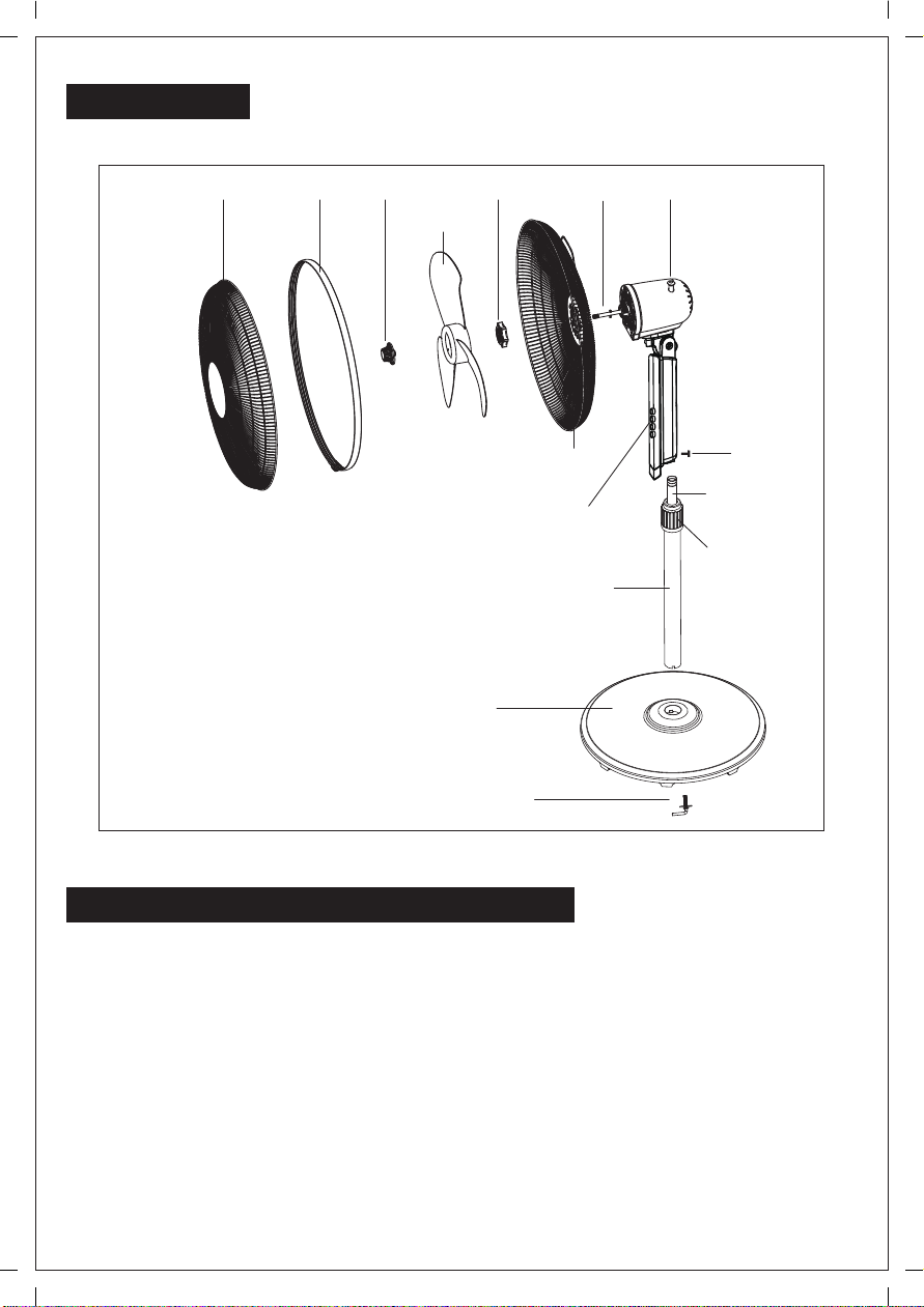
PARTS NAME
Front guard
Note: All the pictures in this manual are for
explanation purpose only. Any discrepancy
between the real object and the illustration
in the drawing shall be subject to the real
subject.
Spinner Clutch knob
Plastic nut Motor shaftCirclip
Blade
Extension pole
Chassis
“7”finger screw
Rear guard
Internal pole
Piano keys
Height
adjustment
ring
Screw
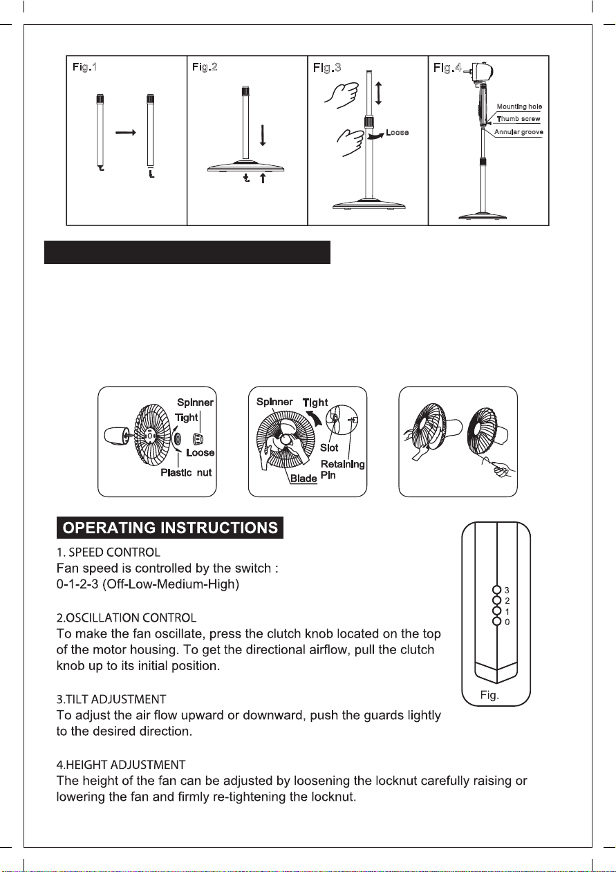
ASSEMBLY OF CHASIS & COLUMN UNIT
1. Unscrew the “7” finger screw from the Extension Pole. (Fig.1)
2. Insert the extension pole in the chassis and tighten the “7” Finger screw. (Fig.2)
3. From the extension pole loosen the height adjustment ring and adjust the internal
pipe to the desired height. (Note: If you can’t find the internal pole, it slides inside
the extension pole. You can pull it out from the extension pole.) (Fig.3)
4. To attach the head unit to the extension pole, loosen the thumb screw on the
bottom of the head unit. Place the head unit on the extension pole and tighten the
thumb screw in alignment with the groove on the internal pole. (Fig.4)
CAUTION: Height adjustment ring must be fully fastened before the assembly of
the motor section to the extension pole.
2
Page 4
145x210mm
Fig.1 Fig.2
F
ig.3
Loo
ig.4
F
Mounting hole
Thumb screw
se
Annular groove
GUARD & FAN BLADE ASSEMBLY
1. Unscrew the spinner clockwise (or take the spinner out from the bag) and the
plastic nut counter clockwise to remove both of them. Fix the rear guard to the
motor then tighten the plastic nut again. (Fig. 5)
2. Insert the blade into shaft, and make sure the rotor shaft pin is fitted into groove
of the blade. Turn the spinner counter clockwise to tighten the blade. (Fig. 6)
3. Fix the front guard and the rear guard with circlip and then tighten the fan guard
locking screw and nut. (Fig. 7)
Fig.5 Fig.6 Fig.7
3
8
Page 5

145x210mm
MAINTENANCE INSTRUCTION
The fan requires little maintenance. Do not try to fix it by yourself. Refer it to qualified
service personnel if service is needed.
1. Before cleaning and assembling, fan must be unplugged.
2. To ensure adequate air circulation to the motor, keep vents at the rear of the
motor free of dust. Do not disassemble the fan to remove dust.
3. Please wipe the exterior parts with a soft cloth soaking a mild detergent.
4. Do not use any abrasive detergent or solvents to avoid scratching the surface.
Do not use any of the following as a cleaner: gasoline, thinner, bending.
5. Do not allow water or any other liquid into the motor housing or interior parts.
CLEANING
1. Be sure to unplug from the electrical supply source before cleaning.
2. Plastic parts should be cleaned with a soft cloth moisten with mild soap.
Thoroughly remove soap film with dry cloth.
4
Page 6

145x210mm
PERHATIAN
Sila baca arahan-arahan keselamatan pengendalian dan penggunaan
dengan teliti.
AMARAN
1. Sekiranya kord kuasa sudah rosak, ia mesti diganti oleh pengilang atau
ejen perkhidmatannya atau orang berkelayakan yang seumpamanya bagi
mengelakkan sebarang kemalangan.
2. Hanya untuk kegunaan di dalam rumah.
3. Untuk menghindari risiko berlakunya kejutan elektrik, jangan
rendamkan unit ini, kord atau plagnya di dalam air atau cecair yang lain.
4. Perkakas ini bukan direka untuk digunakan oleh individu (termasuk kanak kanak) yang kurang upaya fizikal, deria atau mental, atau kurang
pengalaman dan pengetahuan melainkan pengawasan atau arahan
penggunaan perkakas ini telah diberi oleh orang yang bertanggungjawab
ke atas keselamatan mereka. Kanak-kanak hendaklah diawasi bagi
memastikan mereka tidak mempermainkan perkakas ini.
5. Jauhkan peralatan elektrik daripada dicapai oleh kanak-kanak atau orang
kurang upaya. Jangan biarkan mereka menggunakan kipas ini tanpa
pengawasan.
6. Setelah kipas ini dipasang, penghadang pemutar bilah tidak boleh
ditanggalkan sama sekali.
- Tanggalkan plag kipas sebelum kerja pembersihan dijalankan.
- Penghadang pemutar tidak boleh ditanggal/dibuka bagi mencuci bilah
pemutar.
- Lap penutup kipas dan penghadang pemutar bilih dengan kain yang
sedikit basah.
ARAHAN KESELAMATAN PENGENDALIAN
1. Jangan masukkan jari, pensil, atau apa-apa objek lain menerusi
penghadang ketika kipas ini berpusing.
2. Tanggalkan plag sebelum kipas ini dipindah dari satu tempat ke tempat
lain.
3. Pastikan kipas ini diletakkan pada permukaan yang stabil ketika
beroperasi bagi mengelakkan ia daripada terbalik.
4. Jangan letakkan kipas ini di tepi tingkap kerana air hujan mungkin
menimbulkan kebahayaan.
5. Hanya untuk kegunaan di dalam rumah.
5
Page 7

145x210mm
NAMA-NAMA BAHAGIAN
Penghadang
hadapan
Nota: Semua gambarajah dalam buku panduan
ini hanya untuk tujuan penjelasan. Sebarang
perbezaan di antara objek sebenar dengan
ilustrasi dalam lukisan hendaklah tertakluk
kepada subjek sebenar.
Pengetat Tombol
Lingkaran
penghadang
Nat plastik Aci Motor
Bilah Kipas
Penghadang
belakang
Butang piano
Tiang penyambung
Tapak
Skru berbentuk “7”
Skru
Tiang dalaman
Gelang pelaras
ketinggian
PEMASANGAN TAPAK DAN TIANG
1. Longgarkan skru berbentuk “7” pada tiang penyambung (Gambarajah 1).
2. Sisipkan tiang penyambung ke dalam tapak dan ketatkan skru berbentuk “7”
(Gambarajah 2).
3. Longgarkan gelang pelaras pada tiang penyambung dan laraskan paip dalaman
kepada ketinggian yang dikehendaki (Nota: jika anda tidak terjumpa paip dalaman,
ia mungkin tergelongsor ke dalam tiang penyambung. Anda boleh tarik ia keluar
dari tiang penyambung) (Gambarajah 3).
4. Untuk pasangkan unit motor pada tiang penyambung, longgarkan skru ibu jari
pada pangkal unit motor. Letakkan unit motor di atas tiang penyambung dan
ketatkan skru ibu jari sehingga sepadan dengan alur pada paip dalaman
(Gambarajah 4).
Amaran: Gelang pelaras mesti diketatkan dengan teguh sebelum bahagian motor
dipasangkan pada tiang penyambung.
6
Page 8

145x210mm
Gambarajah 1 Gambarajah 2 Gambarajah 3
Longgarkan
Gambarajah 4
Lubang pemasangan
Skru ibu jari
Alur gegelang
PEMASANGAN PENGHADANG DAN BILAH KIPAS
1. Longgarkan pengetat mengikut arah ikut jam (atau keluarkan pengetat dari beg)
dan nat plastik mengikut arah lawan jam masing-masing. Pasangkan penghadang
belakang pada unit motor dan ketatkan semula nat plastik (Gambarajah 5).
2. Masukkan bilah ke dalam aci, pastikan pin aci rotor dipadankan ke dalam alur
bilah. Putar pengetat mengikut arah lawan jam untuk ketatkan bilah.
(Gambarajah 6).
3. Pasangkan penghadang hadapan dan penghadang belakang dengan lingkaran
penghadang, lepas itu tekan klip untuk ketatkan kedua-dua penghadang
(Gambarajah 7).
Pengetat
Ketat
Pengetat
Ketat
Longgar
Nat plastik
Gambarajah 5 Gambarajah 6 Gambarajah 7
Alur
Pin penyumbat
Bilah
ARAHAN PENGENDALIAN
1. Kawalan kelajuan
Kelajuan kipas boleh dikawal dengan suis:
0—1—2 –3 (Berhenti — Rendah – Sederhana – Tinggi)
2. Kawalan ayuan
Tekan ke bawah atau tarik ke atas tombol ayunan di atas unit
motor bagi membolehkan kipas berayun atau berhenti berayun.
Untuk dapatkan aliran angin pada arah tertentu, tarik tombol ke
atas kepada kedudukan asalnya.
3. Pelarasan kecondongan
Untuk melaraskan aliran angin sama ada secara ke atas atau ke
bawah, tolak penghadang sehingga dapatkan arah yang dikehendaki.
4. Pelarasan ketinggian
Ketinggian kipas boleh diselaras dengan longgarkan gelang pelaras ketinggian
untuk tinggikan atau turunkan tiang penyambung, lepas itu ketatkan gelang pada
ketinggian yang dikehendaki.
7
Gambarajah 8
Page 9

145x210mm
ARAHAN PENYELENGGARAAN
Kipas ini hanya memerlukan penyelenggaraan yang sedikit. Jangan cuba membaiki
kipas ini dengan sendiri. Sila rujuk kepada juruteknik bertauliah jika perlu.
1. Tanggalkan plag sebelum langkah pembersihan dan pemasangan dijalankan.
2. Pastikan bahagian motor mempunyai pengaliran udara yang baik. Pastikan laluan
angin masuk pada belakang penutup motor bebas daripada habuk. Jangan
membuka kipas ini bagi membuang habuk.
3. Lap bahagian luar dengan kain lembut dan bahan pencuci yang lembut.
4. Jangan gunakan apa-apa bahan pencuci atau pelarut yang kasar dan kuat bagi
mengelakkan permukaannya menjadi rosak dan bercalar. Jangan gunakan
mana-mana satu daripada berikutnya sebagai bahan pencuci: gasoline, pencair.
5. Jangan biarkan air atau apa-apa cecair lain mengalir ke dalam penutup motor
atau bahagian dalaman.
PEMBERSIHAN
1. Pastikan plag ditanggalkan dari bekalan elektrik sebelum pembersihan dijalankan.
2. Bahagian plastik hendaklah dibersihkan dengan kain lembut yang dibasahi
dengan sabun yang sederhana. Lapkan lapisan sabun dengan sepenuhnya
menggunakan kain kering.
8
Page 10

145x210mm
前网罩 网箍 后网罩 摇头抽钮电机轴风叶 网罩索母
风叶索母
底盘
电机
紧固螺钉
琴键开关
内立柱管
外接头
外立柱管
注:安装时请以实物为准,图解仅供参考。
“7”字螺栓
一、扇体部分
1.从包装纸箱中取出底盘和内外立柱管总成,拧下立柱管底部的七字形螺栓。(如图一所示)
2.将立柱管底部对准底盘中心槽,按图拧紧七字形螺栓并拧紧。(如图二所示)
3.旋松外接头,将内立柱管调整到适当高度(注意,如果没有发现内立柱管,内立柱管应该滑落到
外立柱管里面,可以从外立柱管内拔出来),旋紧外接头。(如图三所示)
4.旋松机身底部紧固螺钉,将机身部分套在内立柱管上,使螺钉对正内立柱管顶部的环形凹槽,然
后拧紧紧固螺钉。(如图四所示)
9
Page 11

145x210mm
图一 图二
图三 图四
二、网罩和风叶部分装配
1.装后网罩:
。
从电机轴前端旋下风叶索母和网罩索母,然后装上后网罩,再装回网罩索母并且旋紧
(如图五所示)
2.装风叶:
先将风叶后面的凹槽卡在电机轴的限位销上,然后逆时针旋紧风叶索母。(如图六所示)
3.装前网罩:
装前网罩时,先把网罩的装饰环摆正,适当地旋松网箍上的螺钉,然后将前网罩与后网罩对齐,使
后网罩的外环扣在网箍内槽中,然后拧紧网箍上的螺钉即可。(装前网罩方式如图七所示;网箍
结构如图八所示)
螺钉
图五 图六 图七 图八
螺钉
10
Page 12

145x210mm
一、风扇运转
按动琴键开关,可以开停风扇和选择风速。
0---停止 1---低速 2---中速 3---高速
二、左右摇头
需要风扇摇头送风时,应把摇头抽钮向下按。如果需要定向送风,只要把摇头抽钮向上提起即可。
三、高度调节
旋松外接头,将内立柱管调整到适当高度,旋紧外接头。(如图三所示)
四、俯仰送风
调节风扇向上或向下送风时,可轻提或轻按机头或网罩部分进行调整。
注意事项
11
Page 13

145x210mm
保养方法
12
 Loading...