

Page 1

MICROWAVE OVEN
MODEL:
AG930AZJ-P00C
( 220V50Hz)
9 00W
SERVICE MANUAL
CAUTION
BEFORE SERVICING THE UNIT,READTHE SAFETY PRECAUTIONS IN THIS
MANUAL
Page 2

SAFETY PRECAUTIONS
This device is to be serviced only by properly qualified service personnel.
Consult the service manual for proper service procedures to assure continued safety operatio n and for precautions to
be taken to avoid possible exposure to excessive microwave energy.
PRECAUTIONS TO BE OBSERVED BEFORE AND
DURING SERVICING TO AVOID POSSIBLE
EXPOSURE TO EXCESSIVE MICROWAVE ENERGY
A) Do not operate or allow the oven to be operated with the door open.
B) Make the following safety checks on all ovens to be serviced before activating the magnetron or other
microwave source, and make repairs as necessary; (1) interlock operation, (2) pr oper door closing, (3)
seal and sealing surfaces (arcing, wear, and other damage), (4) dam age to or loosening of hinges and
latches, (5) evidence of dropping or abuse.
C) Before turning on microwave power for any service test or inspection within the microwave gene rating
compartments, check the magnetron, wave guide or transmission line, and cavity for proper alignment,
integrity, and connections.
D) Any defective or misadjusted components in the interlock, monitor, door seal, and microwave generation
and transmission systems shall be repaired, replaced, or adjusted by procedures described in this manual
before the oven is released to the owner.
E) A microwave leakage check should be performed on each oven prior to release to the owner.
CAUTION
MICROWAVE RADIATION
DO NOT BECOME EXPOSED TO RADIATION FROM THE MICROWAVE GENERATOR
OR OTHER PARTS CONDUCTING MICROWAVE ENERGY.
Page 3

TABLE OF CONTENTS
(page)
SAFETY PRECAUTIONS------------------------------------
CAUTIONS------------------------------------------------------------------------------------------------1-1
THE HEATING PRINCIPLE OF MICROWAVE--------------------------------------------------2-1
INSTALLATIONS----------------------------------------------------------------------------------------3-1
OPERATING INSTRUCTIONS----------------------------------------------------------------------4-1
SCHEMATIC DIAGRAM--------------------------------------------------------------------------4-1
CIRCUIT DESCRIPTION-------------------------------------------------------------------------4-2
SERVICE INFORMATION-----------------------------------------------------------------------------5-1
TOOLS AND MEASURING INSTRUMENTS------------------------------------------------5-1
MICROWAVE LEAKAGE TEST----------------------------------------------------------------5-2
MEASUREMENT OF MICROWAVE POWER OUTPUT---------------------------------5-3
TROUBLE SHOOTING PROCEDURES------------------------------------------------------5-4
COMMON BREAKDOWN AND MEANS OF REPAIRING-------------------------------5-8
---------------------Inside front cover
I M PORTA N T T H I NG S TO DO P R IO R TO CR I T IC A L PA R T S E RV I CING -------------------------5-9
SAFETY CHECKS AND TESTS AFTER SERVING--------------------------------------5-10
EXPLODED VIEW---------------------------------------------------------------------------------------6-1
REPLACEMENT PARTS LIST-----------------------------------------------------------------------6-1
Page 4
CAUTIONS
Unlike other appliances, the microwave oven
is
high-voltage and high-current equipment.
Though it is free from danger in ordinary use,
extreme care should be taken during repair.
• DO NOT operate on a 2-wire extension cord during
repair and use.
• NEVER TOUCH any oven components or wiring during
operation.
• BEFORE TOUCHING any parts of the oven, always
remove the power plug from the outlet.
• For about 30 seconds after the oven stops, an electric
charge remains in the high voltage capacitor. When
replacing or checking, you must discharge the high
voltage capacitor by shorting across the two terminals
with an insulated screwdriver.
• Remove your watches whenever working close to or
replacing the Magnetron.
• DO NOT touch any parts of the control panel circuit. A
resulting static electric discharge may damage this
P.C.B.
• NEVER operate the oven with no load.
• NEVER injure the door seal and front plate of the oven
cavity.
• NEVER put iron tools on the magnetron.
• NEVER put anything into the latch hole and the
interlock switches area.`
1-1
MICROWAVE RADIATION
Personnel should not be exposed to the
microwave energy which may radiate from the
magnetron or other microwave generating
device if it is improperly used or connection.
All input and output microwave connections,
waveguide, flange and gasket must be secure
never operate the device without a microwave
energy absorbing load attached.
Never look into an open waveguide or antenna
while the device is energized.
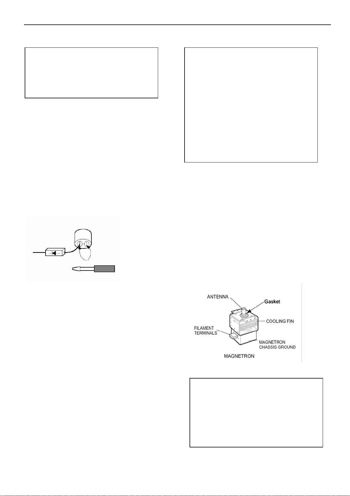
• Proper operation of the microwave oven
requires that
the magnetron be assembled to the waveguide
and
cavity. Never operate the magnetron unless it is
properly installed.
• Be sure that the magnetron gasket is
properly
installed around the dome of the tube
whenever
installing the magnetron.
THE OVEN IS TO BE SERVICED
ONLY
BY PROPERLY QUALIFIED SERVICE
PERSONNEL.
Page 5

THE HEATING PRINCIPLE OF MICROWAVE
Microwave is one kind of radio wave whose wave length is very short, frequency is very high. Therefore, it is called ultrahigh
frequency electromagnetic wave. Microwave can heat food mainly r esult in the mutual affect of the food in the microwave field and
microwave field itself.
Under the affect of microwave field, the thermal effect mechanism produced from the mutual affect of the microwave and the food
includes two aspects: One is Dielectric loss of polar molecule, the other is conductive loss of ion.
Usually, food is constitute of organism (plant and animal).The organism is formed by all kinds of polar water molecule, polar
protein molecule, and all sorts of salt ion. The center of gravity of the positive and negative charge in the molecule is not c oincide.
In normal condition, the molecule is in irregular order due to its thermal action, thus the food do not appear polarity (FIG.11a).Under the action of outer electric field, the positive end of the polar molecule tre nd to the negative electric field, the negative
end of polar molecule trend to the positive electric field, and somewhat arrange in order through the direction of the electric
field(FIG.1-1c).This phenomenon usually be called “TORQUE POLARITY”. When the outer electric field apply for the opposit e
polarity, the polar molecule then arrange an opposite direction order accordingly (FIG.1-1b).If the direction of the outer electric field
changed repeatedly, the polar molecule would repeatedly sway accordingly. During the swaying, it understands that the polar
molecule would produce heat due to somewhat similar friction among them.
When the electric field is applied for ultrahigh frequent microwave field from the outside, its direction would chang e tens billion
times per second, so do the molecule. This kind of molecule swaying producing similar frictional heat from the interference and
block of the action strength among the molecule, and changed to microscopic microwave heating. Microwave heating not only
concerned the nature of the matter itself, but also closely connected with the electric field strength and frequency. When the
frequency is low, the molecule swaying rate and the acute degree of the mutual friction among the molecule is low, and would
produce much heat. When the frequency is too high, as the swing of the polar molecule is with rotating inertia, it made the swing
do not in line with the changing rhythm of the electric field because of the friction drag, thus, actually lowed the polar molecule
swaying speed. The friction dragging degree is concerning a bout the ma gneto electric wave frequency, polar molecule shape, and
the matter’s sticky degree. To different matter’s molecule, there are different special frequency zone. Those ado absorb microwave
energy from these zone are most capable to turn microwave energy to heat energy.
Apart from the above said action, there is another action which is electric ion under t he action of microwave field, act fiercely
accompanied with the acceleration of electric field. The positive ion transfer to the negative polarity of the field while the negative
ion do opposite. Accompanying with the changing electric field, the electric ion changing according ly. During the transferring, heat
produced with the crash among the ion. This kind of action take the main effect to those microwave heating of high salt molecule.
No matter it is the polar molecule swaying or the ion transferring, they both are turning the microwave energy which the heatin g
matter got from the microwave field to hear energy. From the analysis of theory, we can draw such a conclusion that the power
which a unit of volume matter absorbed from the microwave field as the following formula:
Pa=K·E· F·Er·tgδ
Pa Stands for the power the heated matter absorbed from the microwave field.
K Stands for a constant
E Stand for microwave field strength
F Stands for the microwave frequency.
Er Stands for relative dielectric constant of the heated matter.
tgδStands for loss angle tangent of the heated matter
2-1
Page 6

INSTALLATIONS
BEFORE YOU BEGIN, READ THE FOLLOWING INSTRUCTIONS COMPLETELY
INSTALLING
1. Empty the microwave oven and clean inside it with
a soft, damp cloth. Check for damage such as
misaligned door, damage around the door or dents
inside the cavity or on the exterior.
2. Put the oven on a counter, table, or shelf that is
strong enough to hold the oven and the food and
utensils you put in it. (The control panel side of the
oven is the heavy side. Use care when handling.)
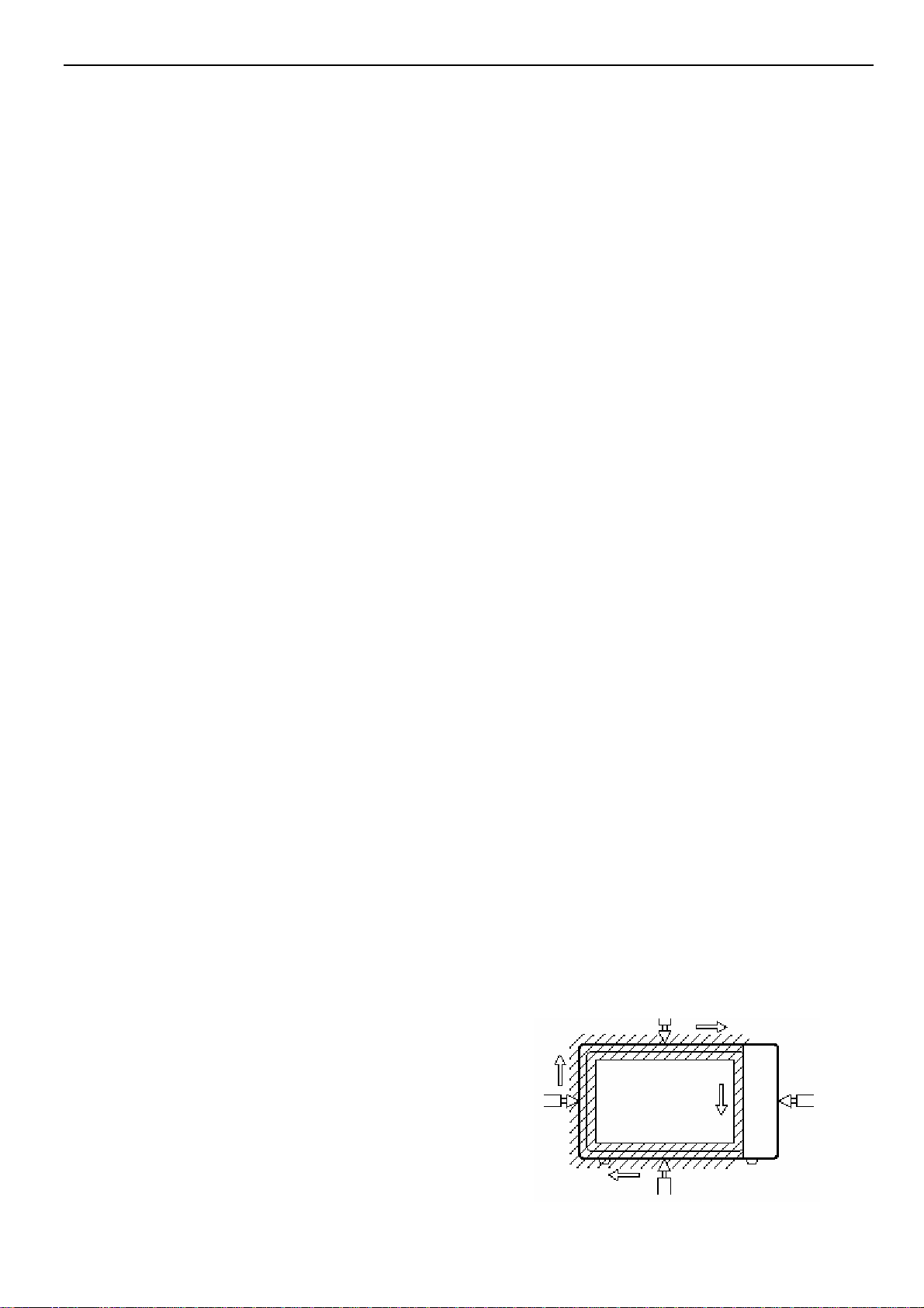
3. Do not block the vent and the air intake openings.
Blocking vent or air intake openings can cause
damage to the oven and poor cooking results.
Make sure the microwave oven legs are in place to
ensure proper air flow.
4. The oven should not be installed in any area where
heat and steam are generated, because they may
damage the electronic or mechanical parts of the
unit.
Do not install the oven next to a conventional
surface unit or above a conventional wall oven.
5. Use microwave oven in an ambient temperature
less than 104°F(40°C).
6. Place the microwave oven on a sturdy and flat
surface at least 10 cm(4 inches) from the wall.
7. Place the microwave oven as far away as possible
from TV, RADIO, COMPUTER, etc., to prevent
interference.
EARTHING INSTRUCTIONS
This microwave oven is designed to be used in a fully
earthed condition.
It is imperative, therefore, to make sure it is properly
earthed before servicing
WARNING-
THIS APPLIANCE
MUST BE EARTHED
IMPORTANT
The wires in this mains lead are colored in
accordance with the following code:
Green-and-yellow: Earth
Blue: Neutral
Brown: Live
As the colors of the wires in the mains lead of this
appliance may not correspond with the colored
markings identifying the terminals in your plug,
proceed as follows.
The wire which is colored green-and-yellow must be
connected to the terminal in the plug which is marked
with the letter E or by the earth symbol (
colored green or green-and-yellow.
The wire which is colored blue must be connected to
the terminal in the plug which is marked with the letter
N or colored black.
The wire which is colored brown must be connected
to the terminal in the plug which is marked with the
letter L or colored red.
) or
3-1
Page 7

SCHEMATIC DIAGRAM
Page 8

CIRCUIT DESCRIPTION
GENERAL DETAILS
• The low voltage transformer supplies the necessary
voltage to the micom controller when power cord is
plugged in.
• When the door is closed, the primary switch is ON, the
secondary switch is ON, and the monitor switch opens
(contact COM and NO).
WHEN SELECTING COOKING POWER
LEVEL AND TIME
• The micom controller memorizes the function you set.
• The time you set appears in the display window.
• Each indicator light turns on to indicate that the stage
has been set.
WHEN TOUCHING THE START PAD
• The coil of the relay is energized by the micom
controller.
• Power input is supplied to the high voltage transformer
through the fuse to the primary switch and relay 2.
• Turntable rotates.
FUSE
L
N
MICOM CONTROLLER
• The fan motor rotates and cools the magnetron by
blowing the air (coming from the intake on the
baseplate)
• The air is also directed into the oven to exhaust the
vapor in the oven through the upper plate.
• Cooking time starts counting down.
• 3.2 volts AC is generated from the filament winding of
the high voltage transformer. This 3.2 volts is applied
to the magnetron to heat the magnetron filament
through two noise preventing choke coils.
• A high voltage of approximately 2100 volts AC is
generated in the secondary of the high voltage
transformer which is increased by the action of the high
voltage diode and charging of the high voltage
capacitor.
• The negative 4,000 Volts DC is applied to the filament
of the magnetron.
WHEN THE OVEN IS SET AT ANY LEVEL
EXCEPT MAXIMUM.
• The micom controller controls the ON-OFF time of relay
2 by the applied signal to vary the average output
PRIMARY
SWITCH
RELAY 2
MONITOR
SWITCH
TRANS-
FORMER
SECONDARY
SWITCH
power of microwave oven as POWER LEVEL.
WHEN THE DOOR IS OPENED DURING
COOKING
• Both the primary switch and relay 2 are cut off primary
winding voltage of the high voltage transformer.
• ON-OFF of relay 2 is coupled electrically with opening
and closing of the secondary switch.
• When the door is opened, the secondary switch is
opened and when the door is closed, the secondary
switch is closed.
• The cooking time stops counting down.
• Relay stops functioning.
• As the door is opened, if the contact of primary switch
and relay 2 and/or secondary switch fails to open, the
fuse opens due to the large current surge caused by
the monitor switch activation, which in turn stops
magnetron oscillation.
FUSE
L
N
MICOM CONTROLLER
PRIMARY
SWITCH
RELAY 2
MONITOR
SWITCH
FORMER
SECONDARY
SWITCH
TRANS-
WHEN TOUCHING THE START KEY
WITH THE GRILL COOKING FUNCTION
SELECTED
• The contacts of the primary switch and the secondary
switch close the circuit.
• A.C.voltage is applied to the grill heater through grill
thermostat as shown by the solid line.
GRILL
THERMOSTAT
L
L
G -Y
N
E
N
• Turntable rotates.
• The fan motor rotates.
• The air is also directed into the oven to exhaust the
vapor in the oven through the base plate and upper
plate.
TOP HEATER RELAY
GRILL
HEATER
4-2
Page 9
SERVICE INFORMATION
TOOLS AND MEASURING INSTRUMENTS
NECESSARY TOOLS
Tools normally used for TV servicing are sufficient.
Standard tools are listed below.
• Diagonal pliers
• Long nose pliers
• Phillips screwdriver
• Flat blade screwdriver
• Wrench (size 5mm)
• Nutdriver (size 5mm)
• Adjustable wrench
• Soldering iron
• Solder
• Vinyl insulation tape
• Polishing cloth
MICROWAVE LEAKAGE TEST
CAUTIONS
• Be sure to check microwave leakage prior to
servicing the oven if the oven is operative prior to
servicing.
• The service personnel should inform the
manufacture importer, or assembler of any certified
oven unit found to have a microwave emission
2
level in excess of 5 mW/cm
unit found to have excessive emission levels at no cost
to the owner and should ascertain the cause of the
excessive leakage. The service personnel should
instruct the owner not to use the unit until the oven has
been brought into compliance.
• If the oven operates with the door open, the service
personnel should:
- Tell the user not to operate the oven.
- Contact the manufacturer.
• The service personnel should check all surface and
vent openings for microwave leakage.
• Check for microwave leakage after every servicing. The
power density of the microwave radiation leakage
emitted by the microwave oven should not exceed
2
5 mW/cm
to assure safety for operating personnel from radiation
leakage.
. Always start measuring of an unknown field
and should repair any
5-1
NECESSARY MEASURING
INSTRUMENTS
• TESTER(VOLTS-DC, AC., Ohmmeter)
• Microwave survey meter
- Holaday HI-1710(A)
- Narda 8100
8200
• Inch scale
• 600 cc non conductive material beaker (glass or
plastic), inside diameter: approx. 8.5 cm(3
• Cylindrical and made of borosilicate glass vessel.
max. thickness: 3 mm
outside diameter: approx. 190mm
height: approx. 90mm
• Glass thermometer: 100°C or 212°F (1 deg scale)
1/2 in.)
MEASURING MICROWAVE ENERGY
LEAKAGE
• Pour 275±15 cc of 20±5°C(68±9°F) water in a
beaker
which is graduated to 600 cc, and place the beaker
on the center of the turntable.
• Set the energy leakage monitor to 2,450 MHz and
use it following the manufacturer's recommended
test procedure to assure correct result.
• When measuring the leakage, always use the 2-
inch (5 cm) spacer supplied with the probe.
• Operate the oven at its maximum output.
• Measure the microwave radiation using and
electromagnetic radiation monitor by holding the
probe perpendicular to the surface being measured
Move probe along shaded area
Probe scanning speed: Less than 2.5 cm/sec
Page 10

MEASUREMENT WITH OUTER CASE
REMOVED
• When you replace the magnetron, measure for
microwave energy leakage before the outer case is
installed and after all necessary components are
replaced or adjusted.
Special care should be taken in measuring the
following parts.
- Around the magnetron
- The waveguide
WARNING : AVOID CONTACTING ANY
(Magnetron, H.V. Transformer,
H.V. Capacitor, H.V. Cable Ass’y,
H.V. Fuse)
HIGH VOLTAGE PARTS
MEASUREMENT WITH A FULLY
ASSEMBLED OVEN
• After all components, including the outer case, are fully
assembled, measure for microwave energy leakage
around the door viewing window, the exhaust opening,
and air inlet openings.
• Microwave energy leakage must not exceed the values
prescribed below.
NOTE: Leakage with the outer case removed less than
2
3 mW/cm
oven (Before the latch switch (primary) is
interrupted) with the door in a slightly opened
position-less than 1 mW/cm
. Leakage for a fully assembled
2
NOTES WHEN MEASURING
• Do not exceed meter full scale deflection.
• The test probe must be removed no faster than
1 inch/sec (2.5 cm/sec) along the shaded area,
otherwise a false reading may result.
• The test probe must be held with the grip portion of
the
handle.
A false reading may result if the operator's hand is
between the handle and the probe.
• When testing near a corner of the door, keep the
probe
perpendicular to the surface making sure the probe
horizontally along the oven surface, this may possibly
cause probe damage.
RECORD KEEPING AND NOTIFICATION
AFTER MEASUREMENT
• After adjustment and repair of any microwave energy
interruption or microwave energy blocking device,
record the measured values for future reference. Also
enter the information on the service invoice.
• The microwave energy leakage should not be more
2
than 1.0 mW/cm
good condition, functioning properly and genuine
replacement parts which are listed in this manual have
been used.
• At least once a year, have the electromagnetic energy
leakage monitor checked for calibration by its
. after determining that all parts are in
5-2
Page 11

MEASUREMENT OF MICROWAVE POWER OUTPUT
• Microwave power output measurement is made with
the microwave oven supplied at its rated voltage and
operated at its maximum microwave power setting with
a load of (1000±5) g of potable water.
• The water is contained in a cylindrical borosilicate glass
vessel having a maximum material thickness of 3 mm
and an outside diameter of approximately 190mm.
• The oven and the empty vessel are at ambient
temperature prior to the start of the test.
• The initial temperature (T1) of the water is (10±2)°C It
is measured immediately before the water is added to
the vessel. After addition of the water to the vessel,
the load is immediately placed on the center of the
turntable which is in the lowest position and the
microwave power switched on.
• The time T for the temperature of the water to rise by a
value . T of (10±2)°K is measured, where T is the time
in seconds and .T is the temperature rise. The initial
and final water temperatures are selected so that the
maximum difference between the final water
temperature and the ambient temperature is 2°K.
• The microwave power output P in watts is
calculated
approximately from the following formula :
P=4187 x (△T)/T
is measured while the microwave generator is
operating at full power. Magnetron filament heat-up
time is not included. (about 3 sec)
• The water is stirred to equalize temperature
throughout
the vessel, prior to measuring the final water
temperature.
• Stirring devices and measuring instruments are
selected in order to minimize addition or removal of
heat.
5-3
Page 12

TROUBLE SHOOTING PROCEDURES
Before overhauling a microwave oven, you should judge the breakdown and the cause correctly, then you can repair it with
corresponding ways. The overhauling must be proceed in order, any hasty conclusion is not recommendable, otherwise
overworking would be done when repair. The microwave oven may occur compound breakdown due to all kinds of different
reasons, thus, when overhaul, they all should be taken into consideration. Special attention must be given to the microwave
leakage and the electric insulation when examine because they may do harmful to the repairing staff.
Ⅰ.MEANS OF THE BREAKDOWN EXAMINING
How to examine a microwave oven with breakdown? A better means which demonstrated in practical operating are through
inspecting and listening. On the basis of large amounts of perceptual knowledge, you can judge and analysis the breakdown
quickly and correctly.
1. Inspection.
Inspect whether the oven shape is disordered and where is the disordered position, if any. It is normal if the outer case
disordered a little, but abnormal if the oven, the door disordered, the door hook broken, the door crooked, or there are too
much looseness between the door and the oven after the door is closed.
2. Listening.
Listening to the voice of the oven operating and the noise of the fan after it conducted. Minor “wen wen” noise, cycling “kala”
noise and “shishi” noise should be consider as normal. But it is abnormal if the following noise occurred:
(1) Sound “wenwen” noise.
(2) Long time “shishi” noise.
(3) Strike voice like “pipa pipa”.
Ⅱ.SPOT EXAMINING STEPS OF THE MICROWAVE OVEN.
1. Examine the microwave insulating resistance.
Measure the insulating resistance with a multi meter or a mega ohmmeter. The value should not less than 2 mega ohm.
Otherwise, part examination should be taken at once. Such as checking whether the motor, the thermal cutout, the
transformer or the capacitor are electricity leaking.
2. Examination of the resistance value of the microwave oven.
Close the door, set the time (the oven is at operating condition but the power plug haven’t been pl ugged in), measure the t wo
feet(L-N)of the power plug with Rx1 grade of a multimeter, the resistance value should be about 22 ohm.
If open circuit occurred, then you must check whether the 10 A fuse is broken、the primary winding of the transformer is open
circuit、the thermal cutout is open circuit or not, you must check whether the interlock device is put through or all the plugs
are connected well. If short circuit occurred, you should check whether the primar y winding of the power transformer is shortcircuited or part short-circuited.
3. Examination of microwave leakage
Measure the microwave leakage with a microwave leakage Measure. Place a graduat e of 275ml water at the middle of the
glass tray of the oven (FIG.5-1). Close the door, power set high, time set to 3 minutes, press the starting button to operate the
oven. After rectified the microwave leakage measure, measure around the door crack, those hole position of the window and
the air vent at four sides of the oven with the probe of the measure. When meas ure, the moving speed of the probe should
not exceed 2.5cm per second, and the measuring direction should be the same with the outing direction of the microwave
leakage (FIG.5-2).
When measuring, the ultimate value of microwave leakage of all the measured position should not exceed 1.0 mili watt/cm
or should be considered as abnormal.
FIG.5-1
275ml
Glass tray
FIG.5-2
5-4
2
,
Page 13

4. Examine when the oven at operating, but the food can’t be heated
Pull out the power plug, take off the outer case, discharge the capacitor, measure the resistance value of the primary winding and
the secondary winding of the transformer with a multi meter (FIG.5-3 and FIG.5-4). The resistance value of the primary winding
should be about 2.2 ohm, the secondary winding should be about 13 0 ohm, otherwise, it indicates the transformer has broken,
and should be replaced by a new one.
If the transformer is normal, then the high voltage capacitor should be checked. Pull out the connecting plug of the capacitor,
and measure it with Rx1 grade of a multi meter, the two rod of the multi meter connect the two polarity of the capacitor. When
they just connected, the reading of the multi meter should be zero, then enlarge to nine mega ohm slo wly. Change the rod to
different polarity, the reading repeat from zero to 9 mega ohm (FIG.5-5),it means the capacitor is normal. If the indicator of the
multi meter can’t point out from zero to 9 mega ohm, it indicates the high voltage capacitor has broken, and should be
replaced by a new one.
If it is normal between the two pole of the capacitor, then the insulation between the capacitor pole and the cabinet (FIG.5-6)
should be checked.
If the resistance value between the capacitor pole and the cabinet is “∞”,the capacitor is normal. Then c heck the earth of the
magnetron’s two filament to see whether they are short-circuited (FIG.5-7).If they are short-circuited and the filament strikes
the shell of the magnetron, it indicates the magnetron has broken, and should be replaced by a new, same model one.
If there is no problem with the magnetron, check the high voltage diode then. Measure the diode with Rx10k grade of a multi
meter, the “-” rod end of the multi meter connect the cathode of diode, the “+ “ rod end of the multi meter connect the anode of
the diode(FIG.5-8).The multi meter reading should be about 150 thousand ohm. Then change the rod to different
electrode(FIG.5-9), the reading should be “∞”.If the reading is very small, and near to short circuit, it indicates the high
voltage diode has been punctured, and should be replaced by a ne w one.
If high voltage diode is also normal, then test the pilot switch(FIG.5-10). Pull out the two plugs of the switch, Measure it with
the Rx1 grade of a multi meter, the two rod connect the plug of the switch, the resistance value should be “∞”.Then press
down the pilot switch with a screwdriver, if the reading of the multi meter pointed to zero, it indicates the pilot switch has
broken, and should replace it with a new, same model one.
FIG5-5
FIG.5-7
FIG5-6
FIG.5-8
5-5
Page 14

Ⅲ.REPAIRING METHOD OF SEVERAL BREAKDOWN
1. Repair when there occurred large amounts microwave leakage. There are many factors, which may cau se microwave l eaking.
Following mentioned may be the main cause of microwave leakage:
(1) The door deformed, the hinge loosed or damaged that caused the door can not close tightly.
(2) The door pressing cover or the embed piece damaged or come off.
(3) Obvious damage or uneven of the oven.
(4) There are filth between the door and the oven.
(5) The door and the oven are serious loosed after the door closed.
(6) The crack of the door shielding net cover.
Before repairing, check whether the above listed point are existed, if not, you can start the microwave oven. Place a
graduate of about 275ml water at the middle of the glass tray, close the door, time set at 3 minutes, power at high,
makes the oven operating in normal. Rectify the microwave leakage measure, measure the amount of the microwave
leakage around the oven with its probe. If there are places which the leakage exceed the standard requirement, then
repair them accordingly. If the leakage amount exceed 1.0 mW/cm
take down the outer case, adjust the screws of the hinge to less the gap bet ween the door and the ove n. Then measur e
again, the leakage amount should less than 1.0 mW/cm
some allowance.
If the leakage occurred at the right door crack, adjust the screws that fix the interlock holder and the hook. If the leaka g e
is on the larger side at the right-above of the oven, then adjust the upper screw. Loosen out the screw, push the door
close to the oven to hook the door hook with the plastic parts, then tighten the screw again. If the leakage is larger at
the right-below, then adjust the lower screw. Loosen the screw, push the door close to the oven to hook the door hook
with the switch holder tightly, then tighten the screw again, and open and close the door repeatedly to check whether the
door can operate flexibly, whether the hook and the switch are in their normal position. If it is not in position, then adjust
the door hook and the switch holder the loose between the door and the oven, then measure the leakage with
microwave leakage measure again.
If there still exist microwave leakage, measure near the magnetron with the pr obe of the micro wave leakage m easure. If
the leakage is larger, the oven should be turned off and check whether the 2 or 4 screws which fix the magnetron have
been loosed, if loosed, twist them tightly with socket wrench. If the screws are fixedly, then the magnetron should be
take down to check the copper filament weaved washer of the magnetron has been placed well or whether the wave
guide housing coupling has been oxidized or have lacquer on it. If do have, scrape the oxi dized layer or the lacquer off,
when fix the magnetron, the copper filament weaved washer must be placed well, the screws must be twist tightly. Then
turn on the oven and measure again until it complies with the re quirement. If the microwave leakage is larger at those
hole position of the window board, the oven should be tur ned off to inspect whether there are crack among them. If
several holes formed a crack, it would enlarge the microwave leakage. If that is the case, it indicates the door has
broken, and should be replaced with a new door.
FIG.5-9
2
at the left door crack, then pull out the power plug,
2
. Generally, it should be controlled below 0.8 mill watt/cm2 with
5-6
FIG5.10
Page 15

2. Means of repair when the oven can heat, but the turntable glass can’t move
Firstly, check whether the turntable holder is placed correctly. If it is correct, then pull out the power plug and take down the
turntable combination, measure the resistance value of the turntable motor with Rx1k grade of a multi meter If it is opencircuited, it indicates the turntable motor has broken, and should be replaced by a ne w, same model one. If the resistance
value is between 15-22k,it indicates the turntable motor is normal, then check the connecting shaft weave. If the plastic that
the shaft insert in has broken, a new shaft weave should replace it.
3. Repair when the oven can heat, but the lamp is not on.
Pull out the power plug, take down the outer case and discharge the capacitor.
Pull out the two terminal plugs of the lamp, measure the two plugs of the lamp with the Rx100 grade of a multi meter. If it is
open-circuited, it indicates the lamp has broken, and should be replaced b y a same model one.
4. Means of repair when the oven stop working after several minutes operating
The phenomenon indicated the thermal cutout is playing its protective role, and you should check whether the fan is working
in normal. Turn off the oven, pull out the power plug, take down the outer case, discharge the capacitor, then turn the fan with
hand to see whether it is moving flexibly. If not, it indicates that the oil bearing of the fan motor has run off the oil, and should
take down the fan combination to repair the motor. Loosen the two screws which fix the bearing out the shaft and the bearing,
and rinse them with kerosene (ATTENTION: The bearing can only be wiped with a silk which moistened with kerosene rather
than be washed in the kerosene because there are felt on it. If the felt are soaked with kerosene, then the engi ne oil can not
be sucked up.).After the bearing being cleaned, the felt should be refueled full y with engi ne oil(for when the oven is operating,
the engine oil empty into the oil bearing slowl y).Fix the bearing cover with two screws, turn the fan around till it can move
flexibly. Than install them to the oven, and plug in the two terminal plugs.
If the fan can move flexibly, then the winding of the fan motor should be examin ed. Measure the winding with Rx100 grade of
a multi meter, if it is open-circuited, it indicates the winding of the fan motor has broken, and should be replaced by a new,
same model one.
5-7
Page 16

MOTOR TEST PROCEDURE
COMPONENTS TEST PROCEDURE RESULTS
Fan Motor
(Wire leads removed)
Turntable Motor
(Wire leads removed)
Measure the resistance.
(Ohm-meter scale:R×100)
Measure the resistance.
(Ohm-meter scale:R×1000)
Normal:Approx. 47Ω
Abnormal:
∞ or Several Ω
Normal:Approx. 3.2kΩ
Abnormal:
∞ or Several Ω
NOTE:
z A MICROWAVE LEAKGE TEST MUST ALWAYS BE PERFORM ED WHEN THE UNIT IS
SERVICED FOR ANY REASON.
z MAKE SURE THE WIRE LEADS ARE IN THE CORRECT POSITION.
z WHEN REMOVING THE WIRE LEADS FROM THE PARTS,BE SURE TO GRASP THE
CONNECTOR ,NOT THE WIRES.
5-8
Page 17

COMMON BREAKDOWN AND MEANS OF REPAIRING
PHENOMENON CAUSE REPAIRING MEANS
1.When starting the
oven, the lamp is not on,
the turntable tray can’t
rotate and the food can’t
be heated
2.When starting the
oven, the lamp is on, the
turntable rotating, the fan
cycling but the food can’t
be heated.
3.The food can be
heated, but the lamp is
not on.
4.The food can be
heated but the turntable
tray is not rotating.
5.The oven can heat
within 2-3 minutes, but
can not heat from the
fourth minutes.
6.When starting the
oven, it can’t heat, and
with “wenwen” noise
7.The oven can heat,but
with sound “shishi” noise
8.Large amount of
microwave leakage
9.The door can’t open 1. After long time using, the wear and the rust-
10.The door release
button fall off
11.Electricity leaking The earthing insulation resistances of all the
1. fuse broken
2. The primary and secondary winding of the
transformer are short-circuited.
3. The earthing or the polarity of the capacitor is
punctured.
4. The pilot switch can’t cut off.
5. The interlock switch hasn’t closed.
6. The power plug and the socket are not in good
connection.
7. The door hook broken.
1. The primary and secondary winding, the
filament of the transformer are open-circuited.
2. The magnetron filament is open-circuited, the
magnetic steel of the magnetron broken or the
magnetron is air leaking.
3. Time and power distributor broken..
4. The plugs of the magnetron of the capacitor
loosed.
1. The lamp broken.
2. The plug fall off.
1. The turntable motor broken
2. The plug fall off
3. Connecting shaft weave broken
1. The winding of the fan motor in open-circuited.
2. The fan falls off
3. The plug of the fan motor falls off
4. The turntable shaft is griped with the motor
bearing.
5. The cooling vent blocked
The high voltage diode was punctured Change a new diode
The iron core of the transformer loosed Change a new transformer
1. The door deformed
2. The door metal net cracked
3. The gap of the door crack is too large
4. The welding point of the oven fall off
5. The screws which fix the magnetron loosed
6. The wave guide connection oxidized
7. The magnetron copper f ilament washer is too
thin cause the wave guide opening not in good
earth.
eaten enlarged the gap of the door shaft and
the shaft hole, thus cause the door crooked.
2. The door hook broken
Wore aged after long time operating Overhaul it or renew it
motors or the transformer are less than 2 mega
ohm.
1. Change a new fuse.
2. Change a new
transformer.
3. Change a new capacitor.
4. Change a new pilot
switch.
5. Change a new interlock
switch.
6. Adjust the connection or
replace it by a new one.
7. Change a new book.
1. Change a new
transformer.
2. Change the magnetron.
3. Change the time power
distributor or the microswitch.
4. Fix them.
1. Change a new lamp
2. Insert the plug again
1. Change the turntable
motor
2. Insert the plug securely
3. Change the weave
1. Change the fan motor
2. Change the fan
3. Insert the plug
4. Overhauling them
5. Repairing it
1. Mend the door
2. Change the door
3. Adjust the gap
4. Change the oven
5. Tighten the screws
6. Scrape the oxidized and
tighten the screws
7. Thick the copper filament
washer
1. Adjust the hi nge to rectify
the position of the door.
2. Change the hook
Test where is the leaking
place, then repair it or
change those damaged
components.
5-9
Page 18

IMPORTANT THINGS TO DO PRIOR TO CRITICAL PART
The following instructions are CRITICAL to the owner’s safety. Be sure to follow all the instructions. Contact the
manufacturer of distributor if you have any question.
1.1 If the oven is operative prior to servicing a Microwave Leakage Test (Microwave Emission Check) should be
performed prior to servicing the oven.
1.2 in the event that any microwave oven found to have microwave emission level in excess of 1 mW/cm
following procedures should be followed:
a. Inform the distributor, importer, or manufacture the finding. Record it in the logbooks well.
b. Repair the unit at no cost to the owner.
c. Investigate the oven and ascertain the cause of the excessive leakage.
d. Hold the oven in your facility and instruct the owner not to use the unit until the oven has been brought into
compliance.
1.3 In the event that the oven operates with the door open. The following procedures should be followed:
a. Tell the user not to operate the oven.
b. Hold the oven in your facility until it is investigated and repaired.
c. Contact the manufacturer immediately.
2. Interlock Assembly Replacement and Adjustment
2.1 If you suspect defective primary, secondary or monitor interlock switches, use your ohmmeter(digital or analog
type the check the electrical continuity.
2.2 Make sure the power cord is pulled out and the high-voltage capacitor is discharged before the electrical
continuity check.
2.3 Set the ohmmeter to “Low Resistance” range and connect both leads (alligator clips) to the switch terminals.
2.4 Open the door and notice the meter reading. The primar y or secondar y inte rlock s witch should sho w an “infinite”
resistance when the door is open. Replace it when it is defective. T he monitor interlock should show a “zero or
near zero” resistance when the door is open. When the door is closed, the readings will be opposite.
2.5 If the oven has been received inoperative due to the failure of the monitored safety(primary and/or secondar y)
interlock(s),you should replace all of the monitored safety interlock switched and the moni tor switch.
3. Door and Hinge Replacement and Adjustment
3.1 Pull the power cord from the outlet. Check the door for warped or damaged areas. Check the h inges for broken
or worn areas. Check other areas such as cracked from glass, broken door latched, worn/cracked viewing
screen and etc.
3.2 After determining the door assembly should be replaced, check the parts list for the correct part number. All oven
door components must be ordered directly from the manufacturer or its authorized distributor.
4. Magnetron Replacement
4.1 Check for the presence of the wire mesh gasket before installation.
4.2 Conduct a Microwave Leakage Test at the magnetron area prior to installing the top cover.
SERVICING
5-10
2
.The
Page 19

SAFETY CHECKS AND TESTS AFTER SERVING
Constructional Checks
If mechanical or electrical(electronic) parts have been replaced be sure to follow the following steps.
1.1 Check for correct wiring, adequate mechanical decrements of parts, and firm connectors.
1.2 Check for adequate grounding.
1.3 Check the following items before turning the oven ON.
1) Proper door closing, seal/choke surfaces, and hinges.
2) No outer case damage.
3) Proper interlock and monitor operations.
Insulation Resistance Test
If the low voltage power supply has been repaired, use a 500 V Mega ohmmeter to measure the resistance between the
primary(Line and Neutral)of the power plug and oper ator accessible metal parts. The resistance should be no less than 2 Mega
Ohms. Repair the oven again when necessary.
5-11
Page 20

+12V
BUZ1
R1
3.3k
D
TR1
8050
此主板上留有一个10pin的插座J1,用以和按键板相连.
J1
10
9
8
1K
7
1K
6
C
CON10
B
A
1K
5
2K
4
2K
3
2K
2
2K
1
VCC
R31
20K
R32
2K
C12
C11
471
471
1 2 3 4 5 6 78
7654321
C101
R103
EE16
T100
IC101
PC817
IC102
PC817
R33
20R
10
1
2
IN
4
R29
3K3
R30
3K3
VCC
R35
10K
102,1KV
D106
12V
UF4002
UF4002
D107
TR2
8050
TR3
8050
DOOR1
E102
470uF,25V
R108
20K
R109
1K
E103
470uF,25V
R104
560R
D11
4148
D10
C103
102
R105
270R
4148
Z100
1N5229B,4.3V
9
83
5V
67
23
1
4
R28
20K
D12
L100
4.7uH,0.3A
J
J
+12
@250mA
R106
VCC
4K7
@250mA
E104
220uF,16V
输出电压调节:5V高减少R106,5V低加
R106。
大
但必须保证
ZERO
RLY1
GRILL
RLY2
MICRO
Z100工作在额定条件。
4148
N
R40
1K
C17
TR4
8050
4148
D13
Title
A3
Date: 18-Sep-2012 Sheet of
File: D:\MyData\
RLY3
J
MOTOR
4.7K
Number RevisionSize
桌面\临时文件夹\AGXEEZ~ 1.DDBDrawn By:
TR7
8550
R42
E100
L101
2.2mH,0.1A
C16
0.1uF
R41
4.7K
4.7uF,400V
R107
3K9
R36
10K
TR6
8550
E101
4.7uF,400V
8
7
2
VCC
D100
CN100
microwave
GRILL
lamp/FAN
5
3
线绕电阻
RX
1
22R,2W
VH5-3
D3
4148
D4
烧烤型/非烧烤型的区别:
4148
烧烤型不装R27,仅装烧烤部分电路(包括R28).
1.
非烧烤型只装R27,包括R28在内的烧烤部分电路不安装.
2.
D5
4148
LED5
LED-4
LED-3 R244K7
LED-2
LED-1
R39
VCC
1K
LED share kathode
(共阴极数码管)
LED: 5X8
R3
BUZZER
4.7K
R2
2K
键输出
R7
键输出
R8
键输出
R9
键输入3
R10
键输入2
R11
键输入1
R12
键输入0
R13
C7
C6
471C8471C9471
471
VCC
C13
CSA1
4MHz
15P
R34
10K
R38
1K
C14
15P
100K
R55
5
131211
abcdefgdp
R14
R15
330
330
IC1
15
LED-D/PH1
16
LED-D/PD2
17
LED-D/PD3
18
LED-D/PB0
19
LED-D/PB1
20
LED-D/PB2
21
LED-D/PB3
22
VDD
23
OSCI/PC0
24
OSCO/PC1
25
BUZZER
TONE/PF0
26
T2/PF1
27
PF2
28
DOOR
PF3
SH69P26-28PIN
4
R16
330
SINO SH69P26
3
987
R17
R18
330
330
PH0/LED-D
PD1/LED-C
PD0/LED-C
PA3/LED-C
PA2/LED-C
PA1/LED-C
PA0/LED-C
PC3/RESER
PE0/CMPO
PE1/CMPN
PE2/CMP1
PE3/CMP2
PC2/T0
2
1
LED1
D1
6
10
4148
R19
R20
R21
D2
4148
330
330
330
14
13
12
11
10
9
8
7
C15
GND
0.1uF
6
RESET
5
4
3
2
1
ZERO
D101
1N4007
1N4007
D103
D104
1N4007
1N4007
R224K7
SWE1
R234K7
SWD1
SWC1
R254K7
SWB1
R264K7
SWA1
R101
C100
100K
102,1KV
R102
100K
R100
100R
D102
1N4007
5
IC100
LNK364
D
S
4
FB
S
3
4
BP
S
S
C102
104
1
RY
1
220K,1W
2 3
VCC
R27
10K
2K
DOOR
C10
471
R43
R37
220
10K
10uF/16V
8
D
C
B
+12
A
V1.0A
Page 21

54321
6
D
C
B
SW1(微波)
SW2(烧烤/组合)
SW3(热风对流)
SW4(解冻)
SW5(时钟/预约)
编码开关
B1
SW6(暂停/取消)
SW7(开始/+30秒)
SW_CONDER
J2
1
2
3
4
5
6
7
8
9
10
CON10
七键一旋按键板标准原理图说明:
1. 按键:七个
2. 编码开关:一个
3. 排线:一组(九根或十根)
九针(或十根)的排线连接插针:焊接到按键板上
4.
5. 十针的插头,用以连接到主板上(请注意:主板上的为10 PIN的插座)
PCB
布板注意:
1.
主板上与按键板之间的连接插座为10PIN,且10脚在上(为GND).
主板上的连接插座凹槽朝外,若凹槽朝里,则按键板使用异向排线与主板连接
2.
3.按键板上的排线第10根线在上,为GND连接线.
D
C
B
A
1 2 3 4 56
Title
Number RevisionSize
B
Date: 18-Sep-2012 Sheet of
File: D:\MyData\
桌面\临时文件夹\按键板~1.DDBDrawn By:
A
Page 22

AG930AZJ
Page 23

E
02
E
04
E
02
WIRE
HEA
T
E
R
E
02
温控器连接线
E
E
04
02
WIRE
HEA
温控器连接线
W
IRE
THERM
滤波板连接线
T
ER_
T
HER
M
OST
OST
A
T_FIL
T
E
AG930AZJ-P00C
A
Page 24

Model :AG930AZJ-P00C/MD930GXE
Material code
Part name
(English)
Description
(English)
Qty. position
251200200368
H.V.Transfor
220V/50Hz
H.V.Transfor
1 MIDEA
Magnetron
2M219J-E522
900W
Outer Cover
T=0.5
PCM white
RoHS Bottom
00500013)
RoHS
315mm 1260g
30mm
T-T Ring
Φ15mm
H.V.Transfor
mer
mer MD-
901CMR-1
YLE
1 E05
261200202090
251200100068 Magnetron
261502637100 Outer Cover
251502610243 Outer Cover
251501400079 Bottom Plate
H.V.Transfor
mer
mer 220V
50Hz 900W
MD-901CMR-
A28L PCM
color plate
outer cover
T=0.5 with
blue easy-to-
tear film and
packge
stuff(ref.2515
Plate,
E25L/E28L
SGCC T=0.7
with packge
stuff(ref.2521
1 E05
1 E01
1 Z24
1 Z24
1 B01
262100500002 Turntable
262200200017
T-T Ring
Ass'y
Turntable
Ass'y
Φ222mm
1 T04
1 T03
Page 25

261200600350 Fan Motor
Fan Motor
MDT-10CEF
25120060014
8
251200600161 Fan Motor
Fan Motor 220-
240V 50Hz
MDT-10CEF
1 W03
261200600690 Fan Motor
Fan Motor 220-
240V 50Hz
MDT-10CEF
1 W03
RoHS fan
60 pcs/ctn, 10
layers
4A(BTTB) 220-
RoHS
stuff
RoHS
packge stuff
RoHS Fan
stuff
Switch
Support A28L
PBT
263600500006 Lamp
Lamp
240V25W T25
(MD )
1 E13
261300900400 Fan
261200300080
Turntable
Motor
WLB2 YZ-
E6120-M02K
blade with
packge stuff
Turntable
Motor MDS-
240V50Hz60
Hz CL.B
EKXINTE
1 W03
1 W02
1 T01
261501500301
261202807130 Harness
251300800011 Fan Support
261301301600
Capacitor
Clamp
Switch
Support
Capacitor
Clamp C23L
SGCC T=0.5
with packge
Harness
EG031A-
P00E-H2
(1569) with
Support
HG23L PP
with packge
1 Z01
1 L05
1 W01
1 L01
Page 26

263600500007 Lamp
Lamp
240V25W T25
(
MD
1 E13
253600503976 Lamp
Lamp
240V25W T25
KEI
1 E13
RoHS Control
Panel
Control Panel
PENDING
ARTWORK
RoHS Power
black
Upper
Plate
Upper
Plate
Quartz
Supporter
Quartz
Supporter
RoHSConnect
(3122)
Grill Tube
Connector
Grill Tube
Connector
RoHS Grill
Bracket
RoHS Dial
Knob
187*2 HG23L
PENDING
ARTWORK
RoHS Lower
roplating
)
251300201833 Control Panel
251505900248
251200701304 H.V.Capacitor H.V.Capacitor 1 E06
251200701657 H.V.Capacitor H.V.Capacitor 1 E06
256201000383 Power Cord
261502701300
251501000005
251202700230 Connector
Dec.
Insulating
FOR YOUR
Cord H05RN-
F
3*1.00mm^2
Insulating
or 120mm
1 C01
1 C02
1 E16
1 G09
1 G06
1 E04+E21
251202701535
256511700634 Grill Bracket
251301600165 Dial Knob
251200410024 Quartz Tube
251304900206
256502500868 Lower Hinge
Control
Window
RoHS Quartz
Tube SH-
50C2511
110V/500W
FOR YOUR
Hinge
assembly
apply to new
Platform,elect
1 E04+E21
1 *
1 C10
2 G02
1 C14
1 B03
Page 27

262100100003 Mica Plate
Mica Plate, ref
AG930AZJ炉门组
件
Button Row
A30L ZJ
RoHS
H.V.Diode
CL01-12 12KV
FUXIN with
cover
261200900030 H.V.Diode
12KV 350mA
CL01-12
1 E07
251200900954 H.V.Diode
12KV 350mA
T3512
1 E07
Harness
magnetron
251203301548 H.V.Fuse
H.V.Fuse GERF-
800mA
SONGSHAN
1 E28
261203300080 H.V.Fuse
H.V.Fuse
800mA 5KV
721
1 E28
Fuse
50V10A )
RoHS Fuse
Better
RoHS
250V KSD201
187#
RoHS
250V KSD90
RoHS
250V KSD1
Door Ass'y Door Ass'y 1 *
25210011001
6 , 500
pcs/box
1 A01
251301910012 Button Row
251200900861 H.V.Diode
251202701048 Harness
350mA 187
中环
between filter
and
Ⅱ
1 C20
1 E07
1 E02
261201200030 Fuse
251201200025 Fuse
251201300630
251201300691
261201300720
Thermostat
90
Thermostat
90
Thermostat
90
T10AH250(2
T10AH250
φ5*20mm
Thermostat
90/80 10A
Thermostat
90/80 10A
Thermostat
90/80 10A
1 E11
1
1 E30
1 E30
1 E30
E11
Page 28

251201300033
250V KSD201
RoHS
250V KSD1
RoHS Metal
0.5mm
RoHS
Interlock
16A 250V
T105 187
Interlock
Switch
RoHS
Interlock
250V T105 LF-
10-02
Interlock
Switch
RoHS
Interlock
250V T125 HK-
14
RoHS Monitor
Switch, KW3A-
RoHS Monitor
250V T105 LF-
251201300064
Thermostat
150
Thermostat
150
RoHS
Thermostat
150 /90 10A
187#Vertical
RoHS
Thermostat
150 /90 10A
250V KSD150
1 E37
1 E37
251201300042
261503202100 Air Guide
251201600002
261201600080
261201600180
Thermostat
150
Interlock
Switch
Thermostat
150 /90 10A
Air Guide
A28L SGCC
Switch KW3A-
10T-t OPEN
Switch 16A
Switch 16A
1 E37
1 W04
2 L03
2 L03
2 L03
251201600003
261201600070
Monitor
Switch
Monitor
Switch
10Z-t, 16A
250V
T105,187
terminal
Switch, 16A
10-02
1 L04
1 L04
Page 29

261201600160
RoHS Monitor
RoHS Wire
Binder white
RoHS Cavity
93*96.5
Interlock
28L
RoHS T-T
7130140008
RoHS Air
7130790001
RoHS Foot
black PPT30
251500100325 Cavity 1 A00
Packing Pad
*I
Packing Pad
A28L
RoHS Filter
MDFLT25A
Pressure
3.5±1MM
Capacitor
15mm
Monitor
Switch
Switch, 16A
250V T125
HK-14
1 L04
252000600000 Wire Binder
252200400440
261301101000
252200100008 T-T Driver
252200700003
256302002770 Foot
Cavity Lamp
Cover
Interlock
Lever
Air Guide
Sponge
Lamp Cover
A28L PET
T=0.1
Lever
E25L/A23L/A
Driver HG23L
PPS
Guide
Sponge, 17L
apply to new
platform,
2 *
1 Z15
1 L02
1 T02
1 *
4 B02
251920000516
256400300033 Filter
262011
262001 Capacitor
Pressure
Capacitor
Capacitor,CT
7
222M/250VA
C length
0.1uF/275VA
C X2,
distance
1 *
1 E10
2 C2、C3
1 C1
Page 30

266004
T18*12*8
Fuse Seat
3.5±1MM
Base
187
3.5±1MM
N)、L(OUT)、N(OUT)
±5%, distance
PCB
h 58*width 40
258601000069 Scrow Ass'y Scrow Ass'y 1 *
ROHS screw
diameter 4.1
Power cord
rear plate*1
tt motor-tt
support*1
268005 Fuse Seat
265001 Base Line
Sieve
Inducrance
,QACC-1
Φ1.0,
18Ts,1.7-
6.5mH
,1KHZ
0.1V
length:8.5±1
5×9.5, with
φ5*20 fuse,
foot length
Line,125mm
AWM 1015
18AWG
yellow and
green wire,
length
1 FILTER
2 FUSE
1 GND
269004
261003
264020 PCB
257012500002 screw gasket
Connection-
Peg
Carbon
Resistor
Connection-
Peg
4.8*0.5mm,
length
Carbon
Resistor
510K/1/2W
15mm length
4±1MM
MDFLT25A,F
R-1/94V0,
thickness
1.6mm,lengt
gasket
4
1 R1
1 *
1
grounding-
257012800001 Screw
RoHSScrew
ST4*8PBHC
1
motor
Page 31
H.V
base plate*4;
Fan
support*2
Thermostat-
support*1
Fan support-
plate*1;switch
plate*2
ourter
plate-cavity*3
257012800003 Screw
ROHS Screw
5#
CT4*8TBHC
17
tranformer-
H.V
Diode-capac
itor
clamp-base
plate*1;
Power cord
grounding-
rear
plate*1;upper
hinge ass'y-
cavity*2;
Upper
Insulating
Plate-
cavity*2;
magnetron-
magnetron
support*3;lo
wer hinge
ass'y-
cavity*2;Air
guide*1;filter
257012800016 Screw
257012800009 Screw
257012800027 Screw
257012800032 Screw
RoHS Screw
4*25TWBHC
OHS Screw
ST3*10PWTH
C (
ROHS Screw
ST4*12PWBH
C
ROHS Screw
26# 4*10TDB
2
3
4
8
motor-Fan
magnetron*2;
Filter-Fan
rear
plate*1COntro
l panel-front
support-front
cover-base
plate*3;ourter
cover-rear
plate*2;base
Page 32

261400125760 PCB
AGLEEZG03-K-CKD
electrolytical
RoHS
electrolytical
electrolytical
electrolytical
RoHS
5.0mm
electrolytical
RoHS
electrolytical
5.0mm)
RoHS plug
W_CKD
ROHS high-
ROHS
N_DIP
263001200022
253001200195
253001200197
capacitance
capacitance
capacitance
capacitance
E_4u7_400_D
10H15_M_10
5_CKD(feet
distance
ROHS
Electrolytical
capacitance
E_470u_25_D
8H14_M_105_
CKD, 5.0mm
Electrolytical
capacitance
E_220u_16_D
6.3H11_M_10
5_CKD,
1 C18
2 E100,E101
2 E102,E103
1 E104
263001200036
253005500206 plug
263001000018
263005000024 optocoupler
capacitance
high-voltage
porcelain
capacitor
capacitance
E_10u_50_D5
H11_M_105(f
eet distance
CN_VH-
5A_B3P7.92_
voltage
porcelain
capacitor
C_102_1KV_
Y5P_M_F5.0_
CKD(feet
distance5.0m
optocoupler
IC_817C_4PI
1 C17
1 CN100
2 C100,C101
2 IC101,IC102
Page 33

263005000022 optocoupler IC101,IC102
263005000025 IC
ROHS
N_8PIN_DIP
Switch
X_230V-50Hz-
CKD
ROHS color
7uH K T52
ROHS color
2mH K T52
ROHS metal
_J
ROHS carbon
ROHS plug
W CKD
ROHS plug
W
RoHS Buzzer
2K_立_CKD
263005200033 transformer
263005300001
263005300002
color wheel
inductors
color wheel
inductors
IC_LNK364P
Transformer
T_DZ16003-
wheel
inductors
L_LGA0410-
4R7KT52E_4.
wheel
inductors
L_LGA0410-
222KT52E_2.
1 IC100
1 T100
1 L100
1 L101
263000100004
263000200001
253005500205 plug
263005500068 plug
metal oxide
film resistors
wire-wound
resistors
oxide film
resistors
RY_220K_1W
film resistor
RX_22R_2W_
J
for door
socket,CN_V
H-
2A_B2P3.96_
for connector
socket
CN_XH-
3A_B3P2.54_
1 RY
1 RX
1 DOOR1
1 CON10
253005900218 Buzzer
BUZ_2020P_
1 BUZ1
Page 34

253005100075 Relay
RoHS Relay
DC_H
ROHS Relay
C_H
RLY_ZW_JZC-
ROHS Crystal
chip SH69P26
AG(M)XEEZB-
RoHS
41 CKD
RoHS Ultra
41 CKD(T52)
RLY_ZW_JQ
X-
78F_T85_12V
1 RLY1(GRILL)
253005100002 Relay
253005100003 Relay
263003000511 Digital tube
253005400233
Crystal
oscillator
RLY_SC_302
WP-1AH-
C_T85_12VD
ROHS Relay
40F_T85_12V
DC_H
Digital tube
MDA-
3482AHG_CK
D 45*35*21.5
red/green
oscillator
OSC_4M_2_3
0PPM_CKD
1
1
1 LED1
1 CSA1
RLY2(MICRO
)
RLY4(MOTO
R)
251402200958
253002000204
263002000015
sinle-chip
microcompute
rs
Rectification
diode
Ultra Fast
Recovery
Rectifier
ROHS empty
chip with
program of
06-R-V1.4B
Rectification
diode
D_1N4007_1
KV_DO-
Fast
Recovery
RectifierD_UF
4002_1A_100
V_D0-
1 IC1
5 D100-D104
2 D106,D107
Page 35

263002200009 Zener diode
ROHS Zener
35_CKD(T52)
ROHS Switch
O-35_CKD
RoHS Smt
KD
RoHS Smt
KD
RoHS Smt
_J_CKD
RoHS Smt
KD
ROHS Smt
/8W_J_CKD
ROHS Smt
D
RoHS Smt
_1/10W_J
263002000005 Switch diode
253001100179 Smt CAP
diodeZ_4V3_1
/2W_B_DO-
diode
D_1N4148_15
0mA_100V_D
CAP
C_0805_471_
50_X7R_K_C
1 Z100
1 D12
7 C6~C12
253001100178 Smt CAP
253001100246 Smt CAP
253001100182 Smt CAP
253000400043 Smt Resistor
253000400040 Smt Resistor
CAP
C_0805_104_
50_Y5V_Z_C
CAPC_0805_
15P_50_NPO
CAP
C_0805_103_
50_X7R_K_C
Resistor
R_1206_0R_1
ROHS Smt
Resistor
R_0805_0R_1
/10W_J_CKD
3
2 C13, C14
1 C103
5
1 JR3
C15,C16,C10
2
JR1,JR2,JR4
~JR6
253000400041 Smt Resistor
253000400036 Smt Resistor
Resistor
R_0805_202_
1/10W_J_CK
Resistor
R_0805_330R
3 R2 ,R32,R33
9
R14~R21,R1
05
Page 36

253000400042 Smt Resistor
ROHS Smt
D
ROHS Smt
1/10W_J
ROHS Smt
D
ROHS Smt
D
ROHS Smt
D
ROHS Smt
D
RoHS Smt
D
ROHS Smt
_1/10W_J
RoHS Smt
1/10W_J
RoHS Smt
D
Resistor
R_0805_332_
1/10W_J_CK
3 R1,R29,R30
253000400035 Smt Resistor
253000400046 Smt Resistor
253000400044 Smt Resistor
253000400045 Smt Resistor
253000400047 Smt Resistor
Resistor
R_0805_220_
Resistor
R_0805_472_
1/10W_J_CK
Resistor
R_0805_103_
1/10W_J_CK
Resistor
R_0805_203_
1/10W_J_CK
Resistor
R_0805_102_
1/10W_J_CK
1 R43
R3,R22~R26
9
4 R34~R37
3
12
,R41,R42,R10
6
R28,R31,R10
9
R7~R13,R38
~R40,R104,
R110
253000400102 Smt Resistor
253000400097 Smt Resistor
263000400028 Smt Resistor
263000400024 Smt Resistor
Resistor
R_0805_104_
1/10W_J_CK
Resistor
R_0805_100R
Resistor
R_0805_20R_
Resistor
R_0805_392_
1/10W_J_CK
2 R102,R111
1 R101
1 R103
1 R107
Page 37

263002300004 Smt Diode
RoHS Smt
(塑封)
ROHS SMT
23_CKD
ROHS SMT
23_CKD
ROHS jumper
mm
ROHS jumper
m
ROHS jumper
mm
ROHS jumper
m
PCB
AG(M)XEEZG-
1 ZD V1.0
ROHS
D
KEY BOARD
Diode
D_1N4148W_
150mA_100V
_SOD-123
3 D10,D11,D13
253002400048 SMT Triode
253002400050 SMT Triode
253006100058 jumper
253006100056 jumper
253006100083 jumper
Triode
Q_S8550M-
D_SOT-
Triode
Q_S8550M-
D_SOT-
J_Cu-
Sn_D0.6_7.5
J_Cu-
Sn_D0.6_10m
J_Cu-
Sn_D0.6_12.5
4
2 TR6,TR7
6 J1-J5,J16
8 J6-J13
3 J14,J17,J18
TR1,TR2,TR3
,TR4
253006100077 jumper
263006000821 PCB
263005500096
connecting
curve
J_Cu-
Sn_D0.6_15m
03-K-CKD
152*65.5
1.6mm CEM-
connecting
curve
CP_XH_JC25
_26AWG_10P
100_80_S_CK
1 J15
1 PCB
1 CON10
Page 38

253005700085 Coding Switch
RoHS Coding
2_26.5_CKD
ROHS Tact
5.0mm)
PCB PCBKEY-
KB V1.0
263005600003 Tact Switch
263006000227 PCB
Switch
B_EC16P24L
20F12V-
Switch
KEY_6X6X5_
180±40gf_CK
D(feet
distance
ZJ-R
146*68.5
1.6mm FR-1
1 B1
7 SW1-SW7
1 KEY-ZJ
 Loading...