

Page 1
3 phase, 380-415V, 50Hz
MDV-V120W/DRN1
MDV-V140W/DRN1
MDV-V160W/DRN1
MDV-V180W/DRN1
Model:
Technical Service Manual
Mini VRF
Page 2

MCAC-VTSM-2016-10 R410A All DC Inverter Mini VRF
Contents
Part 1 General Information ................................................................................. 1
Part 2 Specifications & Performance ............................................................... 10
Part 3 Installation .............................................................................................. 54
Part 4 Troubleshooting ..................................................................................... 70
Page 3

R410A All DC Inverter Mini VRF MCAC-VTSM-2016-10
Page 4

MCAC-VTSM-2016-10 R410A All DC Inverter Mini VRF
General Information 1
Part 1 General Information
1. Product Lineup ..................................................................................... 2
2. Nomenclature ........................................................................................ 3
3. Features................................................................................................. 4
4. Indoor Units Lineup .............................................................................. 8
Page 5
R410A All DC Inverter Mini VRF MCAC-VTSM-2016-10
2 General Information
1. Product Lineup
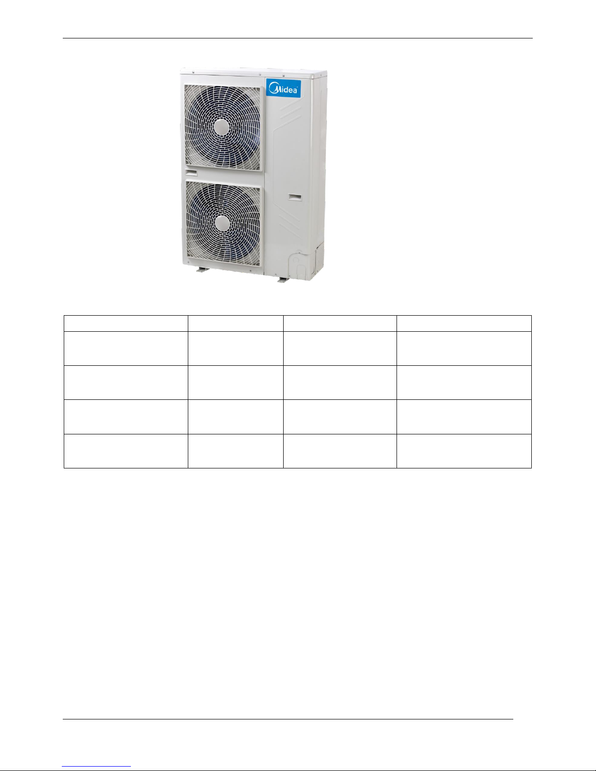
Outdoor Units
Model name
Dimension body(mm)
Net/Gross weight (kg)
Power supply
MDV-V120W/DRN1
Width: 900
Height: 1327
Depth:400
95/106
380-415V-3ph~ 50Hz
MDV-V140W/DRN1
Width: 900
Height: 1327
Depth:400
95/106
380-415V-3ph~ 50Hz
MDV-V160W/DRN1
Width: 900
Height: 1327
Depth:400
102/113
380-415V-3ph~ 50Hz
MDV-V180W/DRN1
Width: 900
Height: 1327
Depth:400
107/118
380-415V-3ph~ 50Hz
Page 6

MCAC-VTSM-2016-10 R410A All DC Inverter Mini VRF
General Information 3
2. Nomenclature
MDV-V120W/DRN1
Refrigerant
N1: R410A
Power Supply
-- 220~240V, 50Hz, 1ph
R 380~415V, 50Hz, 3ph
Outdoor unit
Cooling Capacity (×100W )
Midea VRF
Inverter
DC Inverter
Page 7
R410A All DC Inverter Mini VRF MCAC-VTSM-2016-10
4 General Information
3. Features
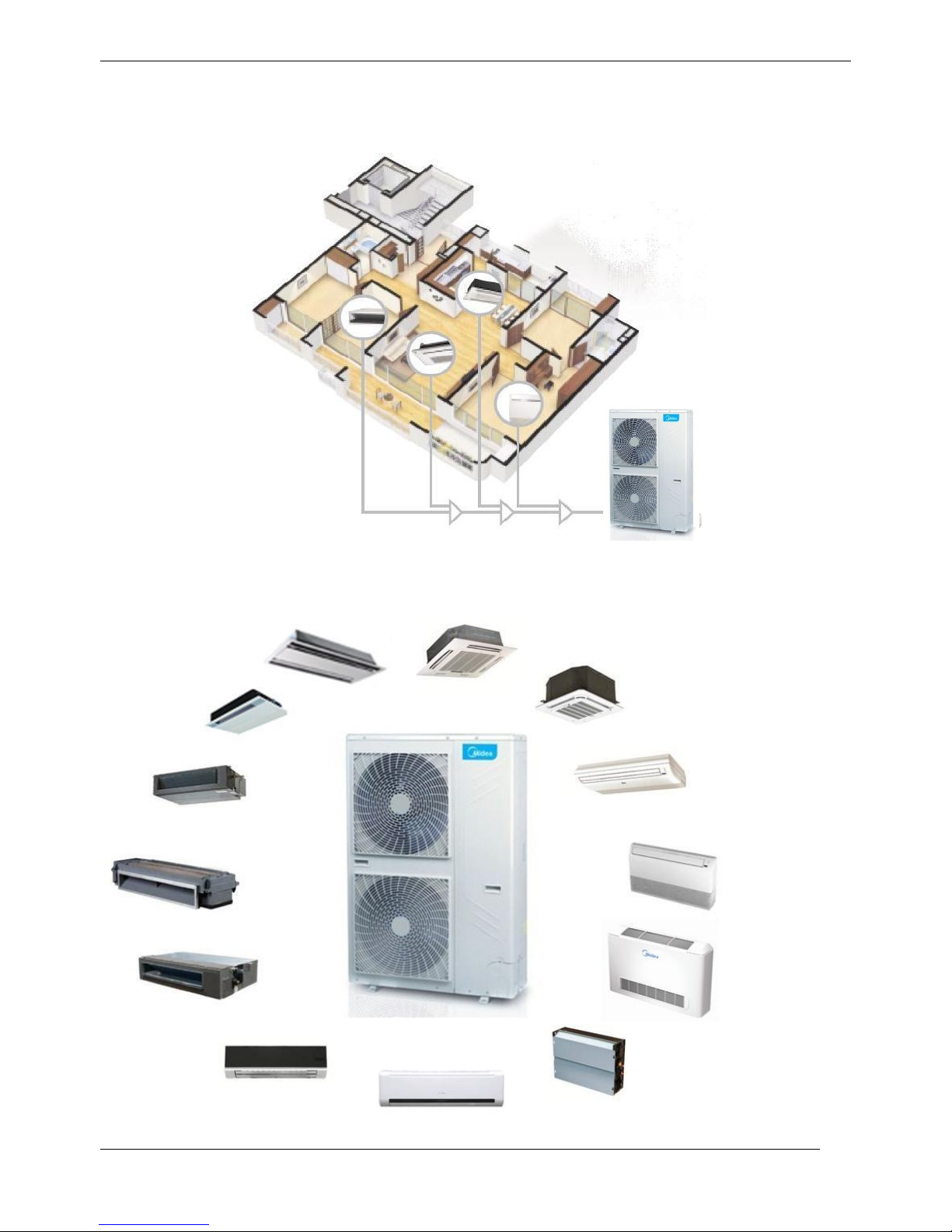
3.1 Wide application
The All DC Inverter Mini VRF system is a highly efficient solution for small commercial buildings requiring
heating and cooling of up to 9 zones with one outdoor unit. Such as villa, restaurant, school etc.
Midea offers various indoor units, more than 100 models of 15 types. Capacity ranges are from 1.5kW to 16
kW. It is all compliance with residential and light commercial place. Our systems can be operated up to 130%
of capacity which allows any system to be designed to the customers’ and applications’ needs.
Page 8
MCAC-VTSM-2016-10 R410A All DC Inverter Mini VRF
General Information 5
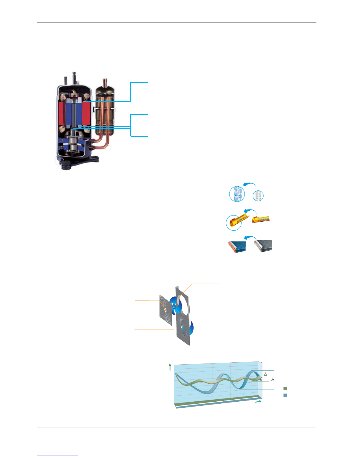
Compressor
(Twin Rotary) structure
3.2 High efficient DC inverter compressor
All DC inverter Mini VRF adopts highly intelligent inverter-driven compressor. This advanced technology
enables the output of the outdoor unit to be modulated by the real heat load demands..
This advanced system ensures precise temperature regulation and highly efficient energy usage, making a
significant contribution to the limiting the impact on the environment.
3.3 High performance heat exchanger
The new designed window fins enlarge the heat-exchanging area ,
which decrease the air resistance, save more power and enhance heat
exchange performance.
Hydrophilic film fins and inner-threaded copper pipes optimize heat
exchange efficiency.
3.4 Low-operating sound design
Optimally design fan shape and new designed discharge air grille and air deflector, making higher air volume
and lower operation sound.
3.5 Quick warm-up & cool-down design and less temperature fluctuation
Utilizing the inverter compressor benefits,
the system can reach All load quickly and
shorten warm-up or cool-down time for an
immediate comfortable air solution.
Less temperature fluctuation will create a
better living environment.
New fan
Air deflector
New grille
Highly Efficient DC Motor:
- Creative motor core design
- High density neodymium magnet
- Concentrated type stator
-Wider operating frequency range
Better balance and Extremely Low Vibration:
- Twin eccentric cams
- 2 balance weights
Highly Stable Moving Parts:
- Optimal material matching rollers and vanes
-Optimize compressor drive technology
- Highly robust bearings
-Compact structure
Fluctuation of room temperature
Cooling operation
2
1
Temp.
Time
Notn-inverter
Inverter
New design Original design
High efficiency inner-thread pipe,
enhance heat transfer.
Page 9
R410A All DC Inverter Mini VRF MCAC-VTSM-2016-10
6 General Information
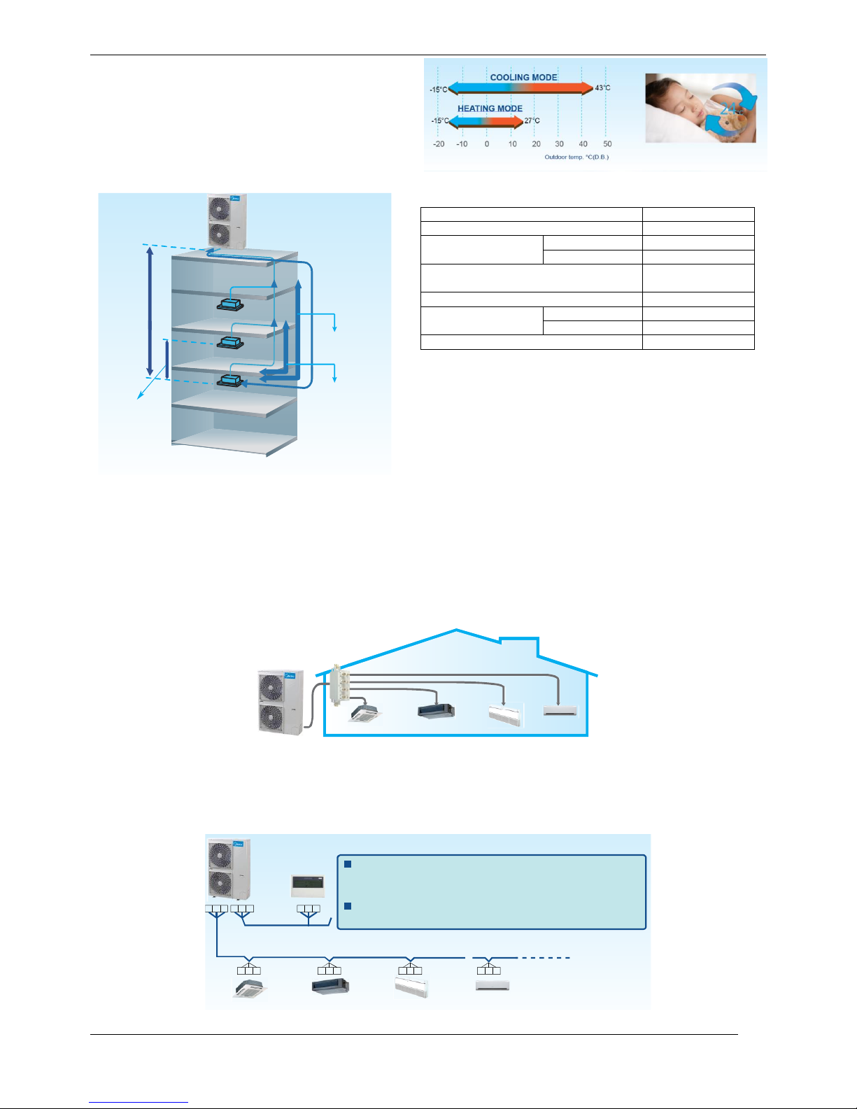
3.6 Wide operation temperature range
No matter in extremely cold winter when outdoor
temperature gets as low as -15°C or in hot summer
when temperature is up to 43°C, the Mini VRF
system will keep stable performance.
3.7 Flexible piping design
3.8 Flexible indoor unit’s connection
Mini VRF with intelligent control gives you independent zoning control with maximum flexibility.
A single outdoor unit supports up to nine indoor units, freeing up considerable space outside. Use your
backyard more wisely with much more space available created by less number of outdoor units.
Max. 6 indoor units for a 12kW outdoor unit installation
Max. 6 indoor units for a 14kW outdoor unit installation
Max. 7 indoor units for a 16kW outdoor unit installation
Max. 9 indoor units for a 18kW outdoor unit installation
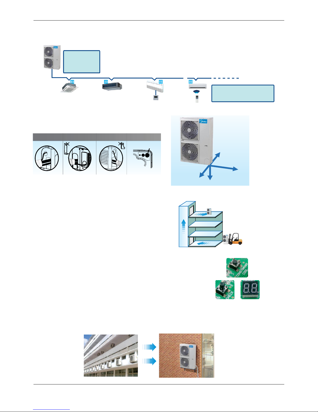
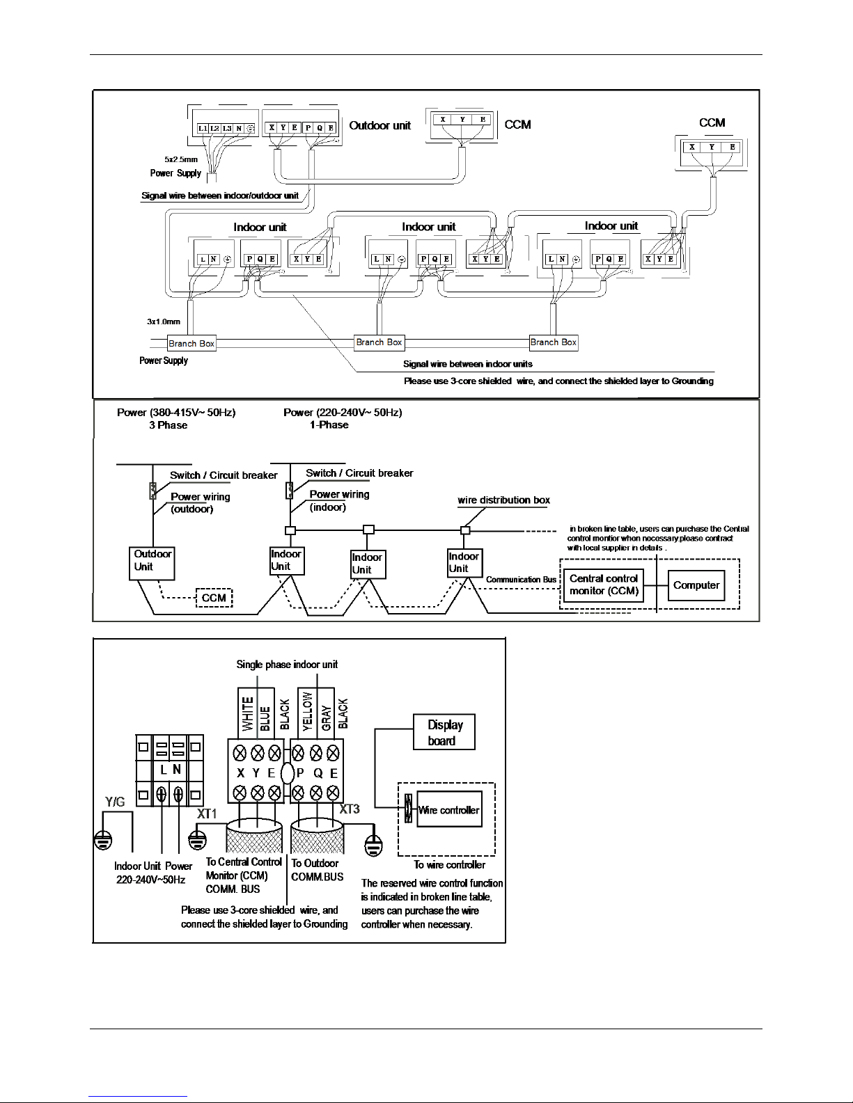
3.9 Simple signal line connection
Installation is much easier as the communication wiring between indoor & outdoor units can be shared.
It’s easy for the user to retrofit the existing system with a centralized control by simply connecting to outdoor
units.
PQE & XYE, just only one group of communication wire of PQE,
achieved both of communication for indoor & outdoor unit and
network.
Reversible communication, central controller can be connected
from indoor side or outdoor side as you wish.
P Q E
P Q E P Q E P Q E P Q E
X Y E X Y E
Piping Length
Permitted Value
Total piping length (Actual)
100m
Longest piping
length
Actual
60m
Equivalent
70m
The first branch joint to the
farthest IDU
20m
The IDU to the nearest branch pipe
15m
Level difference
between ODU~IDU
ODU up
30m
ODU down
20m
Level difference between IDU~IDU
8m
Longest
piping length
Level
difference
between
IDU~ODU
The IDU to the
nearest branch
pipe
The first branch
joint to the farthest
indoor unit
Level differece
between IDU~IDU
Page 10
MCAC-VTSM-2016-10 R410A All DC Inverter Mini VRF
General Information 7
3.10 Auto address setting function
The addresses of indoor units can be set automatically by outdoor unit.
Wired controller and wireless controller can enquire and modify the address of each indoor unit.
3.11 Easy piping connection
Offering four directions to connect pipes and wirings
to meet various installation requests.
3.12 Easy installation
The Mini VRF can be transported by elevator which makes
installation dramatically easy, and effectively reduces time
and labor thanks to the small size.
3.13 Easy maintenance
Forced cooling button makes outdoor unit run in cooling mode at
any condition, so it is very easy for you to charge refrigerant to the
system when it needs to be done. The self-diagnosis function
detects malfunctions in major locations in the system and displays
the type of malfunction and location. This allows service and maintenance
to be performed more efficiently.
3.14 Space saving
The Mini VRF units are more compact, resulting in significant savings in installation space. It is particularly
suitable for small offices, villas, shops, etc.
Outdoor unit can
distribute address
for indoor unit
automatically
Shield signal wire
Wired and wireless controller
can enquire and modify address
of each IDU.
Right side
Upper side
Back side
Front side
Bottom side
Front side
Back side
Right side Bottom side
Fat pipe
Easy to transport
Page 11
R410A All DC Inverter Mini VRF MCAC-VTSM-2016-10
8 General Information
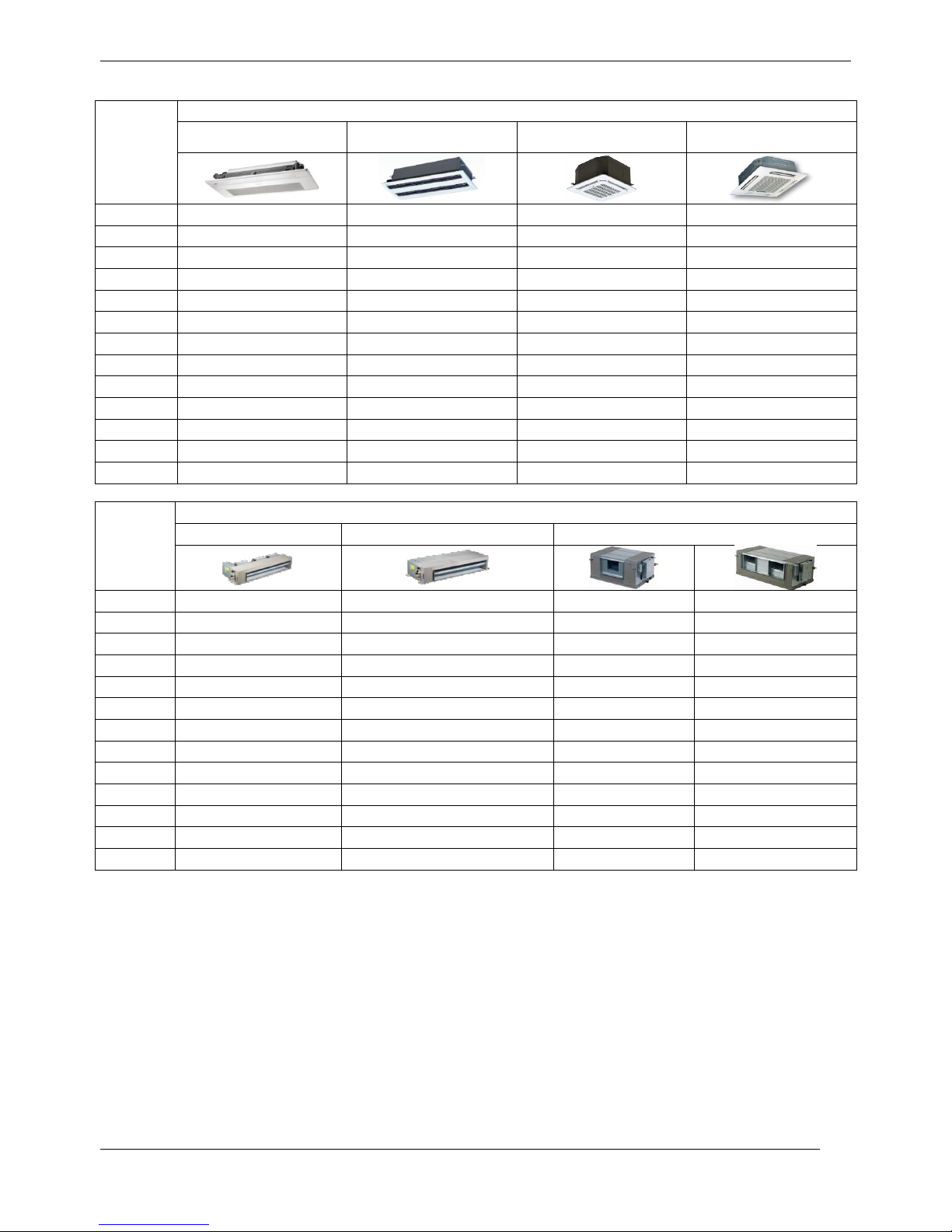
4. Indoor Units Lineup
Capacity
(×100W)
Cassette unit
One-way cassette
Two-way cassette
Compact four-way
cassette
Four-way cassette
15
●
18
●
22
● ● ●
28
● ● ●
●
36
● ● ●
●
45
● ● ●
●
56
●
● ●
71
●
● ●
80
●
90
●
100
●
112
●
140
●
Capacity
(×100W)
Duct unit
Low static pressure duct
Medium static pressure duct
High static pressure duct
15
●
18
●
22
●
●
28
●
●
36
●
●
45
●
●
56
●
●
71
● ● ●
80
●
●
90
●
●
112
●
●
140
●
●
160
●
Page 12
MCAC-VTSM-2016-10 R410A All DC Inverter Mini VRF
General Information 9
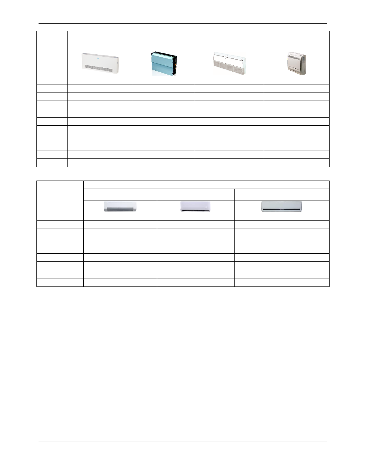
Indoor units lineup
Capacity
(×100W)
Floor-standing/Ceiling & Floor/Console
Floor standing (exposed)
Floor standing
(concealed)
Ceiling & floor
console
22
●
● ●
28
●
● ●
36
● ● ●
●
45
● ● ●
●
56
● ● ●
71
● ● ●
80
● ● ●
90
●
112
●
140
●
160
●
Capacity
(×100W)
Wall mounted
Wall mounted
(S panel)
Wall mounted
(M panel)
Wall mounted
(R panel)
15
●
22
●
●
28
●
●
36
●
●
45
●
●
56
●
●
71
●
●
80
●
●
90
●
●
Note: If ODU connect only one IDU, the capacity of IDU should be not more than ODU.
If ODU connect more than one IDU, the capacity of each IDU should be not more than 8kW for refrigerant uniform distribution.
Due to continuous improvement, specifications are subject to change without prior notice.
Page 13

R410A All DC Inverter Mini VRF MCAC-VTSM-2016-10
10 Specifications&Performance
Part 2 Outdoor Units
1. Specifications ...................................................................................... 11
2. Dimensions ......................................................................................... 14
3. Service Space ..................................................................................... 15
4. Piping Diagrams ................................................................................. 16
5. Wiring Diagrams ................................................................................. 17
6. Field Wiring ......................................................................................... 19
7. Capacity Tables .................................................................................. 20
8. Electric Characteristics ...................................................................... 52
9. Sound Levels ...................................................................................... 53
10. Operation Limits ............................................................................... 53
Page 14
MCAC-VTSM-2016-10 R410A All DC Inverter Mini VRF
Specifications&Performance 11
1. Specifications
Sale Model
MDV-V120W/DRN1
MDV-V140W/DRN1
Power supply
V-Ph-Hz
380-415V-3N~50Hz
380-415V-3N~50Hz
Cooling
Capacity
kW
12.3
14.0
Input
kW
3.25
3.95
EER
kW/ kW
3.78
3.54
Heating
Capacity
kW
13.2
15.4
Input
kW
3.47
4.16
COP
kW/ kW
3.80
3.7
Compressor
Model
TNB306FPNMC
TNB306FPNMC
Type
Rotary
Rotary
Brand
MITSUBISHI
MITSUBISHI
Capacity
Btu/h
33720
33720
Input
W
3010
3010
Rated current(RLA)
A
9.3
9.3
Crankcase W 27
27
Refrigerant oil
ml
FV50S 870+630ml
FV50S 870+630ml
Outdoor fan
motor
Model
WZDK100-38G
WZDK100-38G
Type
DC motor
DC motor
Brand
Panasonic
Panasonic
Insulation class
E E
Safe class
IP23
IP23
Input
W
2 x 100
2 x 100
Output W 2 x 85
2 x 85
Rated current A 2 x 0.9
2 x 0.9
Capacitor
uF / /
Speed
r/min
800
800
Outdoor fan
Material
ASG20
ASG20
Type
Axial fan
Axial fan
Diameter
mm
508
508
Height
mm
170
170
Outdoor coil
Number of rows
2 2
Tube pitch(a)x row
pitch(b)
mm
22 x 19.05
22 x 19.05
Fin spacing
mm
1.6
1.6
Tube outside dia.and type
mm
Ф7.94
Ф7.94
Inner groove tube
Inner groove tube
Coil length x height
mm
1276 x 870
1276 x 870
Number of circuits
7 7
Outdoor air flow
m3/h
6000
6000
Outdoor sound level(sound pressure level )
dB(A)
57
57
Outdoor Unit
Dimension(W x H x D)
mm
900 x 1327 x 400
900 x 1327 x 400
Packing (W x H x D)
mm
1030 x 1456 x 435
1030 x 1456 x 435
Net/Gross weight
kg
95/106
95/106
Refrigerant
Type
R410A
R410A
Charged volume
g
3300
3900
Page 15
R410A All DC Inverter Mini VRF MCAC-VTSM-2016-10
12 Specifications&Performance
Throttle type
Electronic expansion valve
Design pressure
MPa
4.4/2.6
Refrigerant
piping
Liquid side/ Gas side
mm
Ф9.53/Ф15.9
Ф9.53/Ф15.9
Max. refrigerant pipe length
m
100
100
Max. difference in level
m 8 8
Connection
wiring
Power wiring
mm2
5 core x2.5
5 core x2.5
Signal wiring
mm2
3 core shielded wire x
0.75
3 core shielded wire x
0.75
Ambient temp
℃
(Cooling -15~43)
(Heating -15~27)
(Cooling -15~43)
(Heating -15~27)
Sale Model
MDV-V160W/DRN1
MDV-V180W/DRN1
Power supply
V-Ph-Hz
380-415V-3N~50Hz
380-415V-3N~50Hz
Cooling
Capacity
kW
15.5
17.5
Input
kW
4.52
5.3
EER
kW/ kW
3.43
3.3
Heating
Capacity
kW
17.0
19.0
Input
kW
4.77
5.0
COP
kW/ kW
3.56
3.8
Compressor
Model
LNB42FSAMC
LNB42FSAMC
Type
Rotary
Rotary
Brand
MITSUBISHI
MITSUBISHI
Capacity
Btu/h
47700
47700
Input
W
4240
4270
Rated
current(RLA)
A
12
12
Crankcase
W
25
25
Refrigerant oil
ml
FV50S 1400ml
FV50S 1400ml
Outdoor fan
motor
Model
WZDK100-38G
WZDK100-38G
Type
DC motor
DC motor
Brand
Panasonic
Panasonic
Insulation class
E
E
Safe class
IP23
IP23
Input
W
2 x 100
2 x 100
Output
W
2 x 85
2 x 85
Rated current
A
2 x 0.9
2 x 0.9
Capacitor
uF
/
/
Speed
r/min
800
800
Outdoor fan
Material
ASG20
ASG20
Outdoor fan
Type
Axial fan
Axial fan
Diameter
mm
508
508
Height
mm
170
170
Outdoor coil
Number of rows
2
2.5
Tube pitch(a)x
row pitch(b)
mm
22 x 19.05
22 x 19.05
Fin spacing
mm
1.6
1.6
Tube outside
dia.and type
mm
Ф7.94
Ф7.94
Inner groove tube
Inner groove tube
Page 16
MCAC-VTSM-2016-10 R410A All DC Inverter Mini VRF
Specifications&Performance 13
Notes:
1. The cooling conditions: indoor temp.: 27℃DB (80.6℉), 19℃WB (66.2℉) outdoor temp.: 35℃DB (95℉), 24℃WB (75.2℉)
equivalent pipe length: 5m drop length: 0m.
2. The heating conditions: indoor temp.: 20℃DB (68℉), 15℃WB (59℉) outdoor temp.: 7℃DB (44.6℉), 6℃WB (42.8℉)
equivalent pipe length: 5m drop length: 0m.
3. Sound level: Anechoic chamber conversion value, measured at a point 1 m in front of the unit at a height of *m(1.2m for
120~180 model). During actual operation, these values are normally somewhat higher as a result of ambient conditions.
4. The aboved datas may be changed without notice for future improvement on quality and performance.
Coil length x
height
mm
1276 x 870
1276 x 870
Number of
circuits
7
12
Outdoor air flow
m3/h
6000
6800
Outndoor sound level(sound
pressure level )
dB(A)
57
59
Outdoor unit
Dimension
(W x H x D)
mm
900 x 1327 x 400
900 x 1327 x 400
Packing
(W x H x D)
mm
1030 x 1456 x 435
1030 x 1456 x 435
Net/Gross weight
kg
102/113
107/118
Refrigerant
Type
R410A
R410A
Charged volume
g
3900
4500
Throttle type
Electronic expansion valve
Design pressure
MPa
4.4/2.6
4.4/2.6
Refrigerant
piping
Liquid side/ Gas
side
mm
Ф9.53/Ф19.1
Ф9.53/Ф19.1
Max. refrigerant
pipe length
m
100
100
Max. difference in
level
m 8 8
Connection
wiring
Power wiring
mm2
5 core x2.5
5 core x2.5
Signal wiring
mm2
3 core shielded wire x 0.75
3 core shielded wire x 0.75
Ambient temp
℃
(Cooling -15~43)
(Heating -15~27)
(Cooling -15~43)
(Heating -15~27)
Page 17
R410A All DC Inverter Mini VRF MCAC-VTSM-2016-10
14 Specifications&Performance
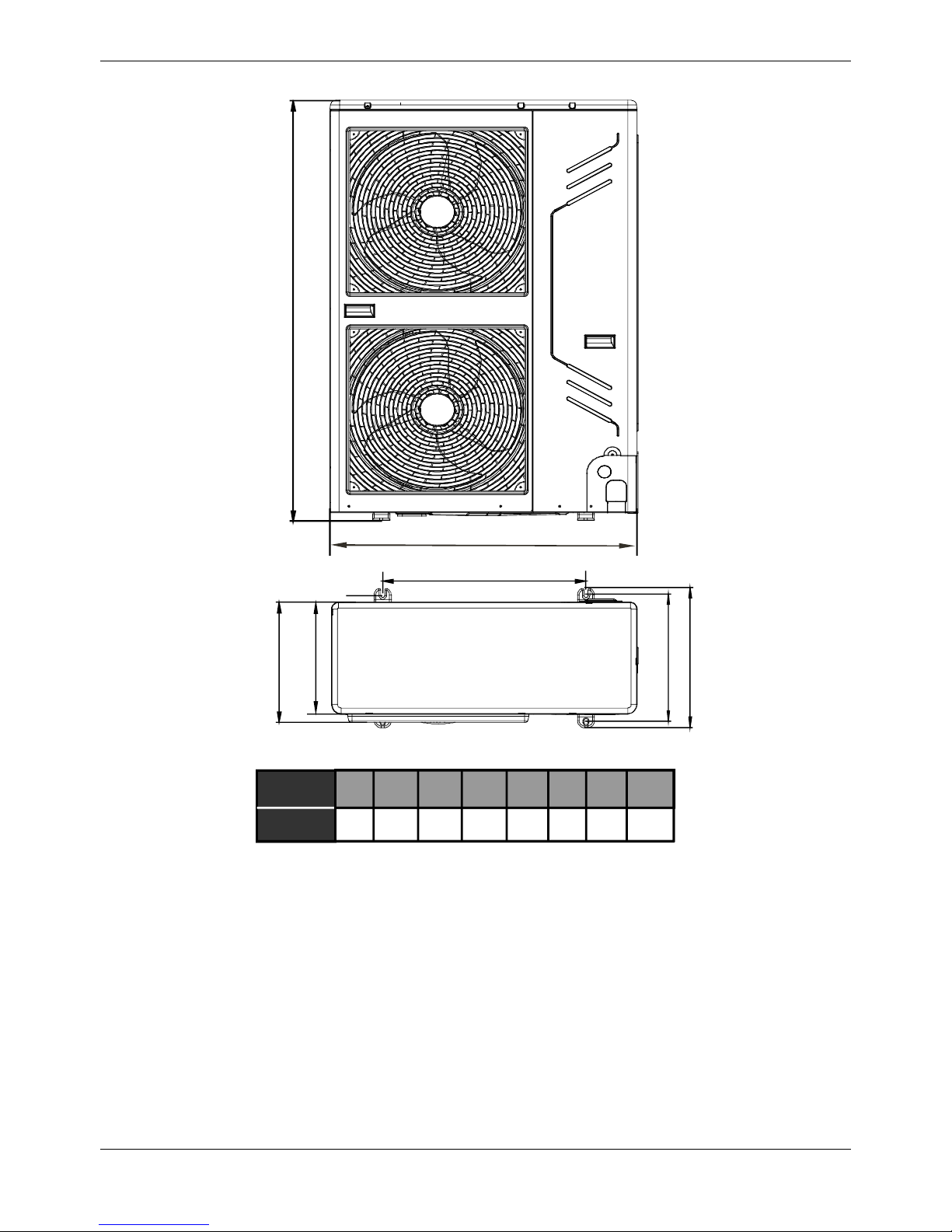
2. Dimensions
H
A
B
C
D
E
F
MODEL
(kW)
900 600 360400 1327
(unit:mm)
348
12/14/
16/18
A
B E
D GFC
320
H
——
Page 18
MCAC-VTSM-2016-10 R410A All DC Inverter Mini VRF
Specifications&Performance 15
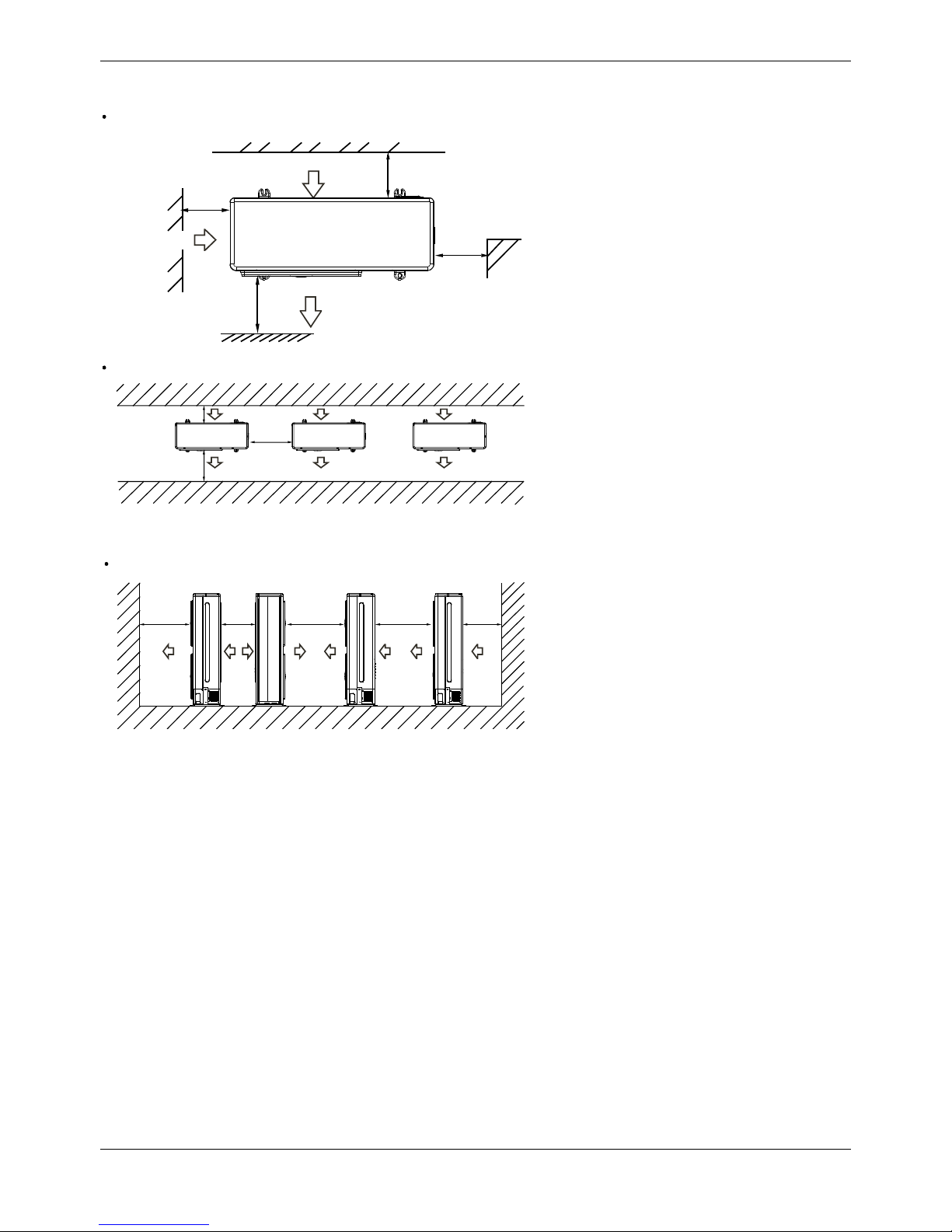
3. Service Space
>300
>600
>300
>
2000
(Wall or obstacle)
Maintain
channel
Air outlet
Air inlet
Air inlet
Single unit installation
>600
>2000
>300
Parallel connect the two units or above
>2000 >500 >3000 >3000 >300
Parallel connect the front with rear sides
Page 19
R410A All DC Inverter Mini VRF MCAC-VTSM-2016-10
16 Specifications&Performance
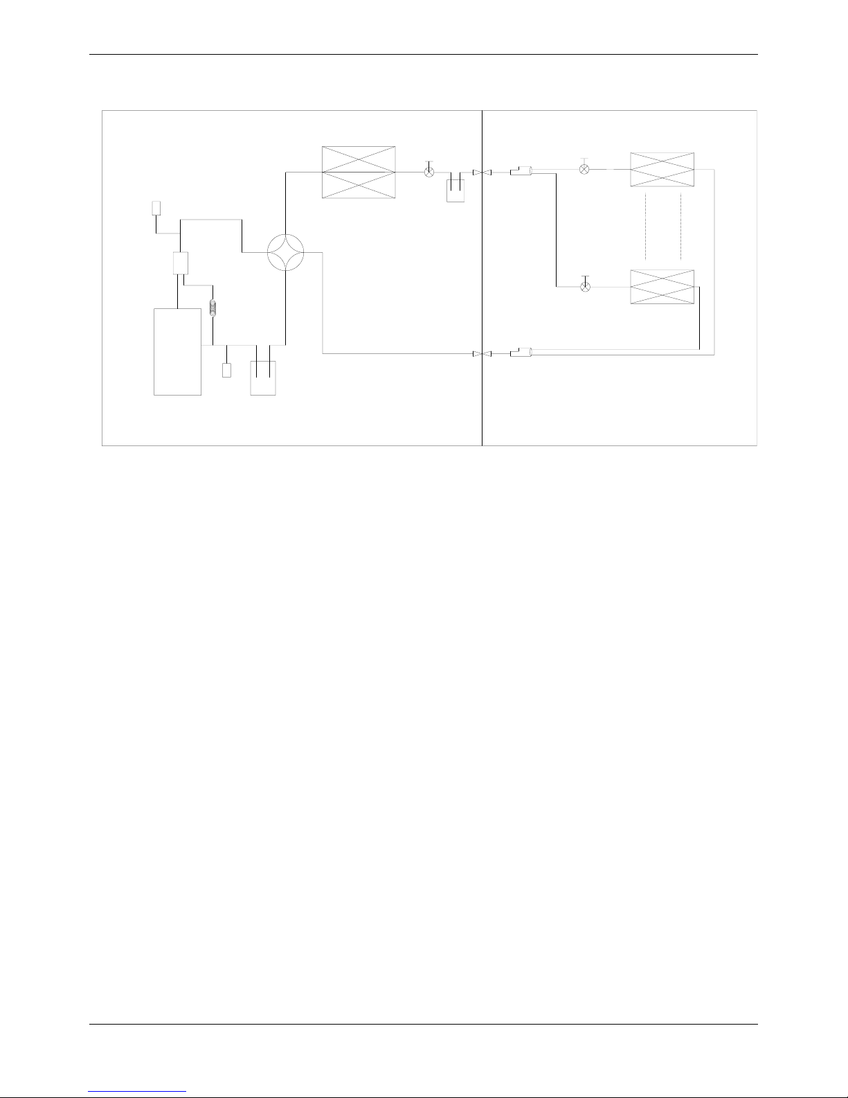
4. Piping Diagrams
High pressure
switch
Oil seperator
Oil return
capilary
Compressor
Low pressure
switch
Low pressure
liquid
accumulator can
Condensor
High pressure
liquid
accumulator
can
Electronic
expansion
valve
Electronic
expansion
valve
Evaporator
Oil separator: used to separate oil from high pressure & temperature gas refrigerant, which is pumped out
from compressor. It makes the oil return back to each compressor very soon.
Low pressure liquid receiver & High pressure liquid receiver: It is used to store the liquid refrigerant and
oil; it can protect the compressor from liquid hammer.
4-way valve: Closed in cooling mode and open in heating mode
Electronic expansion valve: The opening is of the valve is regulated according to the discharge air
temperature of compressor, used to regulating refrigerant flow.
High Pressure Switch: When the discharge pressure of compressor is 4.2Mpa or higher, the protection
switch will be triggered, and if the discharge pressure is down to 3.3MPa, the protection switch will be
recovered.
Low Pressure Switch: When thegas pressureback to compressor is 0.14Mpa or lower, the protection switch
will be triggered, and if the discharge pressure is down to 0.3MPa, the protection switch will be recovered.
Page 20
MCAC-VTSM-2016-10 R410A All DC Inverter Mini VRF
Specifications&Performance 17
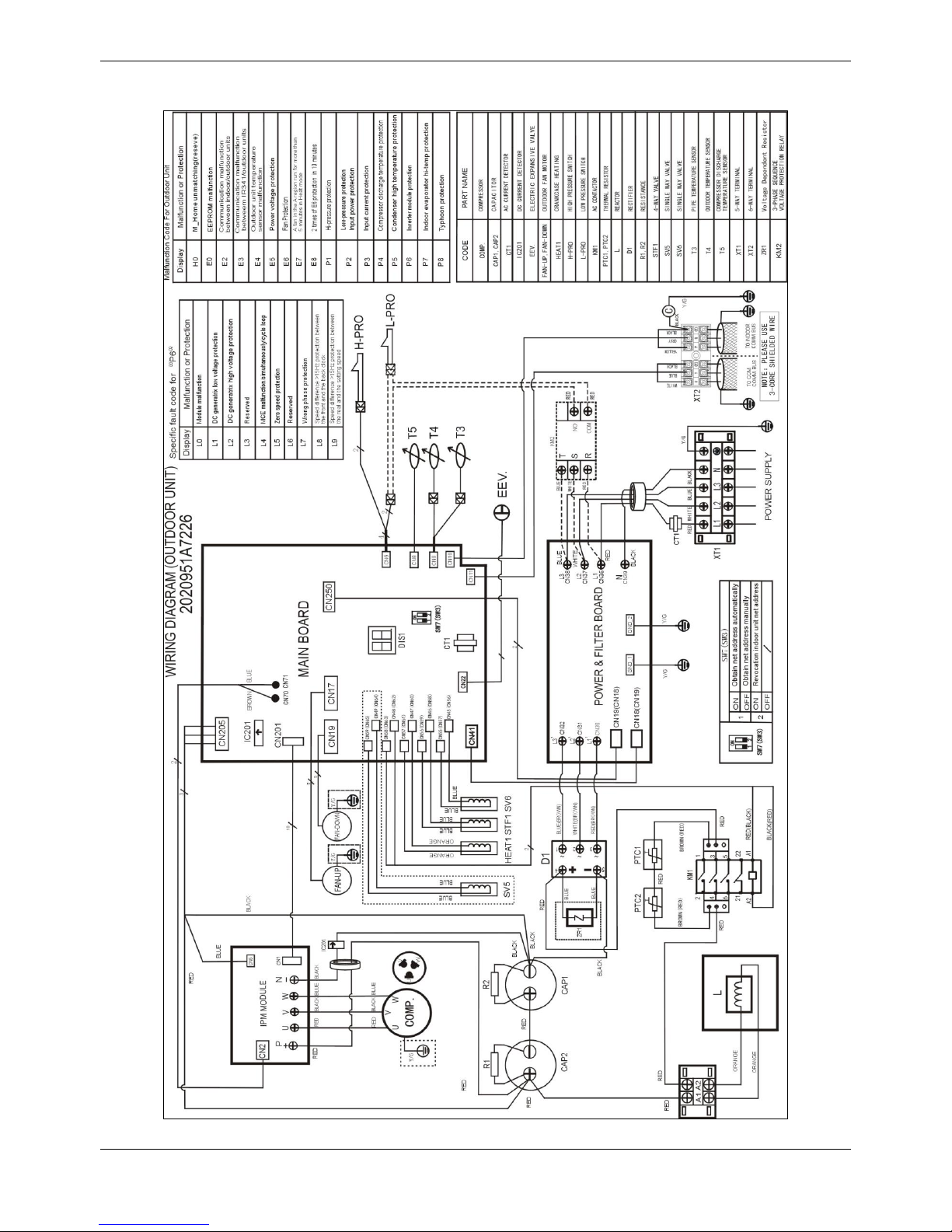
5. Wiring Diagrams(For 12-16kW)
Page 21
R410A All DC Inverter Mini VRF MCAC-VTSM-2016-10
18 Specifications&Performance
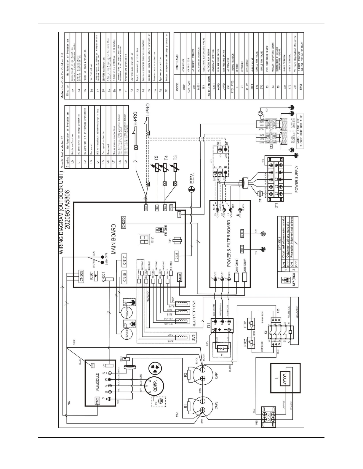
For 18kW
Page 22
MCAC-VTSM-2016-10 R410A All DC Inverter Mini VRF
Specifications&Performance 19
6. Field Wiring
Page 23
R410A All DC Inverter Mini VRF MCAC-VTSM-2016-10
20 Specifications&Performance
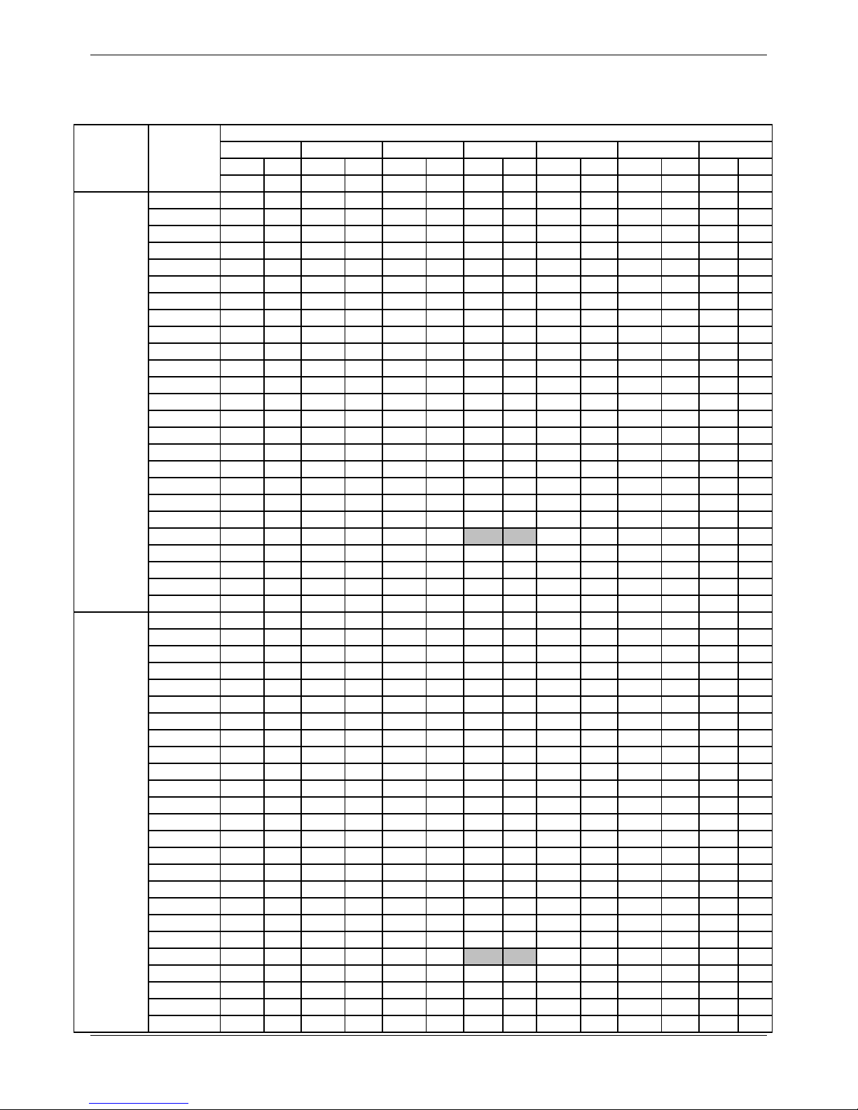
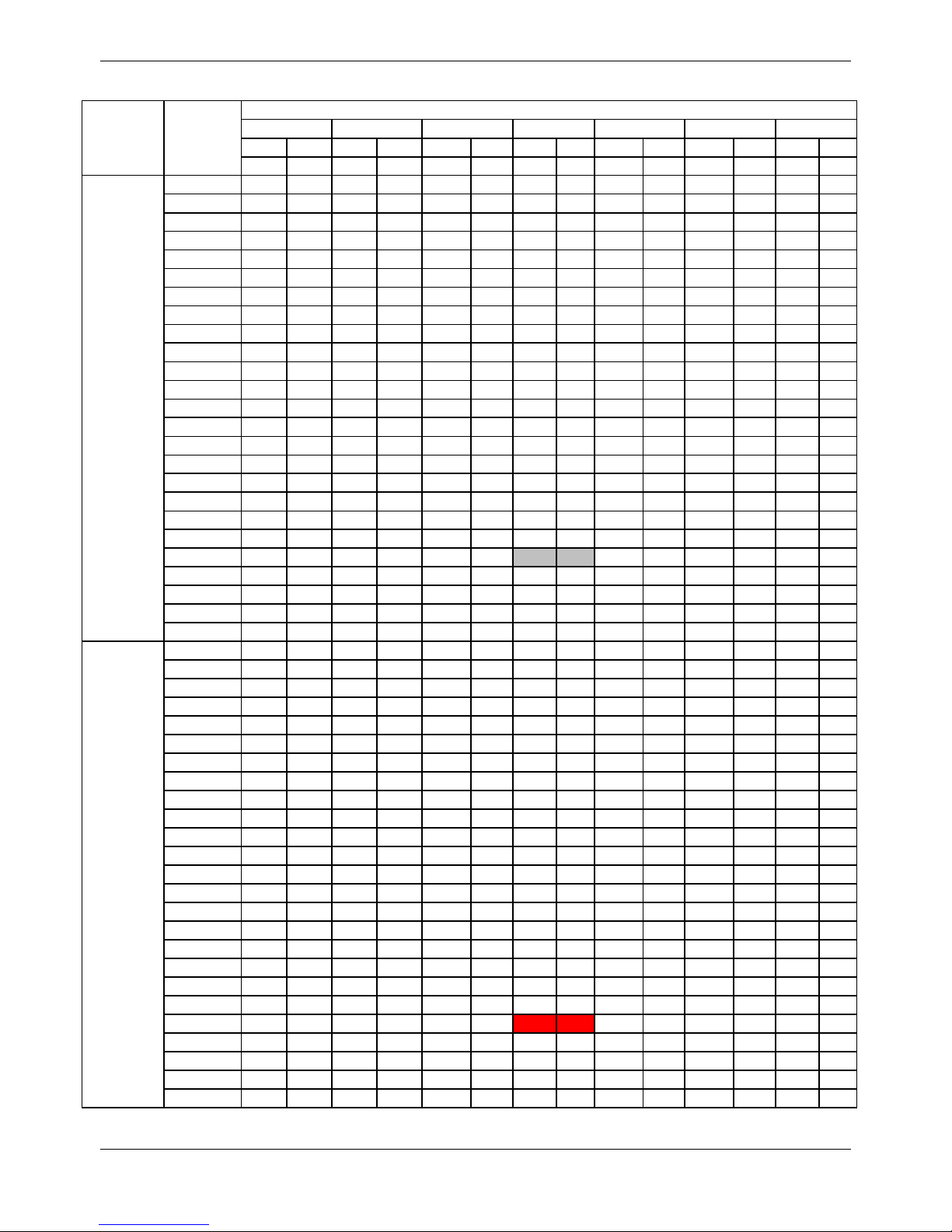
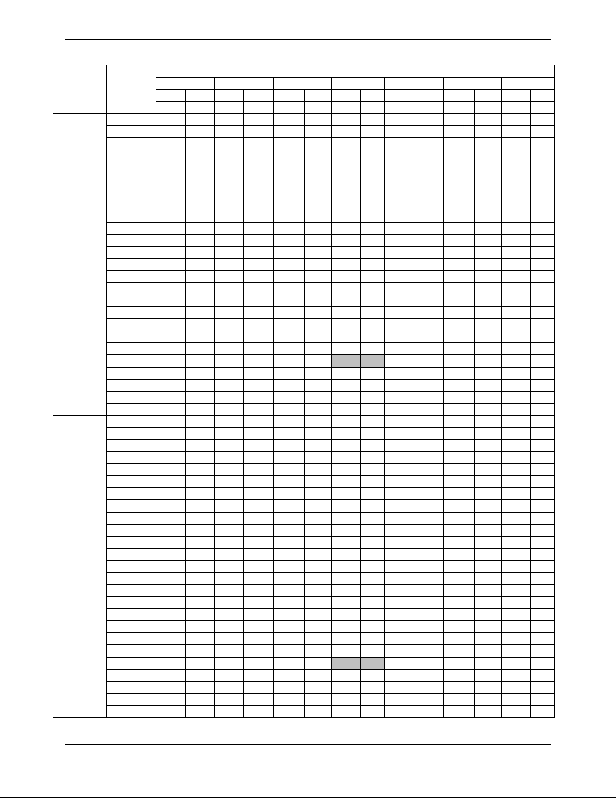
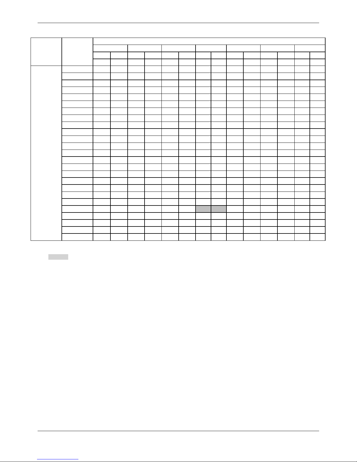
7. Capacity Tables
MDV-V120W/DRN1
Cooling TC: Total Capacity (kW); PI: Power Input (kW) (Compressor + Outdoor fan motor)
Combination
(%)
(Capacity
index)
Outdoor
temperature
(°C DB)
Indoor temperature(°C DB/WB)
DB:20.8,WB:1
DB:23.3,WB:1
DB:25.8,WB:1
DB:27,WB:1
DB:28.2,WB:2
DB:30.7,WB:2
DB:32,WB:2
TC
PI
TC
PI
TC
PI
TC
PI
TC
PI
TC
PI
TC
PI
kW
kW
kW
kW
kW
kW
kW
kW
kW
kW
kW
kW
kW
kW
130%
-5
10.81
1.33
12.87
1.62
14.93
1.74
15.51
1.81
16.25
1.86
16.65
2.02
17.07
2.04
-2
10.81
1.33
12.87
1.65
14.93
1.74
15.51
1.82
16.25
1.86
16.65
2.05
17.07
2.06 0 10.81
1.35
12.87
1.68
14.93
1.8
15.51
1.92
16.25
1.97
16.65
2.07
17.07
2.08 2 10.81
1.38
12.87
1.69
14.93
1.86
15.51
2.03
16.25
1.99
16.65
2.09
17.07
2.11 4 10.81
1.41
12.87
1.72
14.93
1.93
15.51
2.04
16.25
2.02
16.65
2.09
17.07
2.15 6 10.81
1.43
12.87
1.75
14.93
2
15.51
2.05
16.07
2.08
16.44
2.09
16.88
2.17 8 10.81
1.47
12.87
1.79
14.93
2.1
15.51
2.15
15.87
2.15
16.27
3.9
16.66
2.19
10
10.81
1.5
12.87
1.83
14.93
2.18
15.51
2.23
15.68
4.04
16.08
4.06
16.47
2.25
12
10.81
1.52
12.87
1.87
14.93
2.22
15.29
4.03
15.51
4.06
15.86
4.07
16.25
2.27
14
10.81
1.56
12.87
1.9
14.89
4.05
15.11
4.06
15.29
4.08
15.68
4.09
16.08
2.32
16
10.81
1.58
12.87
1.94
14.72
4.06
14.89
4.08
15.07
4.1
15.46
4.12
15.86
2.36
18
10.81
1.61
12.87
1.98
14.5
2.32
14.67
2.33
14.89
2.35
15.29
2.37
15.68
2.39
20
10.81
1.65
12.87
2.11
14.28
2.44
14.5
2.45
14.67
2.46
15.07
2.48
15.46
2.51
21
10.81
1.69
12.87
2.18
14.19
2.49
14.41
2.51
14.58
2.52
14.98
2.55
15.37
2.57
23
10.81
1.81
12.87
2.34
14.01
2.61
14.19
2.62
14.36
2.63
14.76
2.66
15.15
2.69
25
10.81
1.94
12.87
2.51
13.79
2.72
13.97
2.73
14.19
2.75
14.58
2.78
14.98
2.8
27
10.81
2.07
12.87
2.68
13.62
2.83
13.79
2.85
13.97
2.86
14.36
2.9
14.76
2.93
29
10.81
2.21
12.87
2.86
13.4
2.95
13.57
2.97
13.79
2.98
14.19
3.01
14.58
3.04
31
10.81
2.36
12.83
3.03
13.18
3.07
13.4
3.08
13.57
3.1
13.97
3.13
14.36
3.17
33
10.81
2.51
12.61
3.15
13
3.18
13.18
3.2
13.4
3.22
13.79
3.25
14.14
3.29
35
10.81
2.68
12.39
3.26
12.78
3.3
13
3.32
13.18
3.33
13.57
3.37
13.97
3.41
37
10.81
2.85
12.21
3.38
12.61
3.42
12.78
3.43
13
3.46
13.35
3.5
13.75
3.54
39
10.81
3.03
11.99
3.41
12.39
3.53
12.61
3.55
12.78
3.57
13.18
3.61
13.57
3.66
41
10.81
3.19
11.87
3.45
12.26
3.56
12.48
3.59
12.65
3.61
13.05
3.62
13.05
3.69
43
10.81
3.27
11.78
3.46
12.19
3.57
12.41
3.6
12.52
3.61
12.81
3.63
12.9
3.7
120%
-5
9.97
1.28
11.86
1.55
13.79
1.84
14.76 2 15.46
2.09
15.81
2.16
16.17
2.21
-2
9.97
1.3
11.86
1.57
13.79
1.86
14.76
2.02
15.46
2.11
15.81
2.17
16.17
2.22 0 9.97
1.31
11.86
1.58
13.79
1.88
14.76
2.02
15.46
2.13
15.81
2.19
16.17
2.23 2 9.97
1.31
11.86
1.6
13.79
1.89
14.76
2.04
15.46
2.14
15.81
2.2
16.17
2.23 4 9.97
1.32
11.86
1.62
13.79
1.92
14.76
2.06
15.46
2.17
15.81
2.21
16.17
2.24 6 9.97
1.34
11.86
1.63
13.79
1.94
14.76
2.08
15.46
2.19
15.81
2.23
16.17
2.24 8 9.97
1.35
11.86
1.65
13.79
1.97
14.76
2.11
15.46
2.22
15.81
2.23
16.17
2.25
10
9.97
1.37
11.86
1.67
13.79
1.98
14.76
2.15
15.46
2.22
15.81
2.24
16.17
2.26
12
9.97
1.39
11.86
1.7
13.79
2.02
14.76
2.19
15.24
2.23
15.59
2.23
15.95
2.28
14
9.97
1.42
11.86
1.73
13.79
2.06
14.76
2.23
15.02
2.24
15.42
2.26
15.77
2.31
16
9.97
1.45
11.86
1.77
13.79
2.1
14.67
4.1
14.85
2.27
15.2
2.3
15.55
2.34
18
9.97
1.47
11.86
1.8
13.79
2.17
14.45
2.32
14.63
2.33
14.98
2.35
15.37
2.37
20
9.97
1.5
11.86
1.87
13.79
2.34
14.28
2.44
14.45
2.44
14.8
2.47
15.16
2.49
21
9.97
1.52
11.86
1.94
13.79
2.42
14.14
2.49
14.32
2.5
14.72
2.52
15.07
2.55
23
9.97
1.62
11.86
2.08
13.79
2.59
13.97
2.6
14.14
2.62
14.5
2.64
14.85
2.66
25
9.97
1.73
11.86
2.23
13.57
2.71
13.75
2.72
13.93
2.73
14.32
2.75
14.67
2.78
27
9.97
1.85
11.86
2.38
13.4
2.82
13.57
2.83
13.75
2.85
14.1
2.87
14.45
2.9
29
9.97
1.97
11.86
2.54
13.18
2.93
13.35
2.95
13.53
2.96
13.88
2.99
14.28
3.02
31
9.97
2.1
11.86
2.71
12.96
3.05
13.18
3.06
13.35
3.08
13.71
3.11
14.06
3.14
33
9.97
2.24
11.86
2.89
12.78
3.16
12.96
3.18
13.13
3.19
13.49
3.23
13.84
3.26
35
9.97
2.38
11.86
3.08
12.56
3.28
12.74
3.29
12.96
3.31
13.31
3.35
13.66
3.38
37
9.97
2.54
11.86
3.28
12.39
3.39
12.56
3.41
12.74
3.43
13.09
3.46
13.44
3.5
39
9.97
2.7
11.82
3.47
12.17
3.51
12.34
3.53
12.52
3.55
12.91
3.59
13.27
3.62
41
9.97
2.77
11.72
3.49
12.07
3.53
12.25
3.56
12.42
3.57
12.82
3.6
12.88
3.65
43
9.97
2.81
11.66
3.52
11.98
3.55
12.15
3.57
12.33
3.59
12.6
3.61
12.68
3.72
Page 24
MCAC-VTSM-2016-10 R410A All DC Inverter Mini VRF
Specifications&Performance 21
MDV-V120W/DRN1
Cooling TC: Total Capacity (kW); PI: Power Input (kW) (Compressor + Outdoor fan motor)
Combination
(%)
(Capacity
index)
Outdoor
temperature
(°C DB)
Indoor temperature(°C DB/WB)
DB:20.8,WB:1
DB:23.3,WB:1
DB:25.8,WB:1
DB:27,WB:1
DB:28.2,WB:2
DB:30.7,WB:2
DB:32,WB:2
TC
PI
TC
PI
TC
PI
TC
PI
TC
PI
TC
PI
TC
PI
kW
kW
kW
kW
kW
kW
kW
kW
kW
kW
kW
kW
kW
kW
110%
-5
9.14
1.12
10.9
1.39
12.65
1.66
13.53
1.79
14.41
1.92
15.51
2
15.86
2.06
-2
9.14
1.14
10.9
1.41
12.65
1.68
13.53
1.8
14.41
1.94
15.51
2.02
15.86
2.07 0 9.14
1.15
10.9
1.42
12.65
1.69
13.53
1.82
14.41
1.96
15.51
2.04
15.86
2.09 2 9.14
1.18
10.9
1.43
12.65
1.72
13.53
1.84
14.41
1.98
15.51
2.07
15.86
2.12
4
9.14
1.2
10.9
1.45
12.65
1.73
13.53
1.86
14.41
2.01
15.51
2.09
15.86
2.14
6
9.14
1.21
10.9
1.47
12.65
1.75
13.53
1.89
14.41
2.03
15.51
2.12
15.86
2.17 8 9.14
1.23
10.9
1.49
12.65
1.77
13.53
1.91
14.41
2.06
15.51
2.13
15.86
2.2
10
9.14
1.24
10.9
1.51
12.65
1.8
13.53
1.94
14.41
2.09
15.51
2.15
15.86
2.21
12
9.14
1.27
10.9
1.54
12.65
1.83
13.53
1.98
14.41
2.13
15.33
2.18
15.64
2.24
14
9.14
1.29
10.9
1.57
12.65
1.87
13.53
2.01
14.41
2.17
15.11
2.19
15.46
2.26
16
9.14
1.31
10.9
1.6
12.65
1.9
13.53
2.05
14.41
2.21
14.94
2.22
15.24
2.28
18
9.14
1.34
10.9
1.63
12.65
1.94
13.53
2.11
14.41
2.32
14.72
2.33
15.07
2.36
20
9.14
1.36
10.9
1.66
12.65
2.05
13.53
2.27
14.19
2.43
14.54
2.45
14.85
2.47
21
9.14
1.38
10.9
1.71
12.65
2.13
13.53
2.35
14.1
2.49
14.41
2.51
14.76
2.53
23
9.14
1.44
10.9
1.84
12.65
2.28
13.53
2.52
13.88
2.6
14.23
2.62
14.54
2.65
25
9.14
1.54
10.9
1.96
12.65
2.44
13.53
2.7
13.71
2.71
14.01
2.74
14.36
2.76
27
9.14
1.64
10.9
2.1
12.65
2.61
13.31
2.82
13.49
2.83
13.84
2.85
14.15
2.88
29
9.14
1.75
10.9
2.24
12.65
2.79
13.13
2.93
13.31
2.94
13.62
2.97
13.97 3 31
9.14
1.86
10.9
2.39
12.65
2.98
12.92
3.04
13.09
3.06
13.44
3.08
13.75
3.11
33
9.14
1.98
10.9
2.55
12.56
3.14
12.74
3.16
12.92
3.17
13.22
3.2
13.57
3.23
35
9.14
2.11
10.9
2.71
12.34
3.25
12.52
3.27
12.7
3.29
13
3.32
13.36
3.35
37
9.14
2.24
10.9
2.89
12.17
3.37
12.34
3.39
12.48
3.4
12.83
3.44
13.13
3.47
39
9.14
2.38
10.9
3.08
11.95
3.49
12.12
3.5
12.3
3.52
12.61
3.56
12.96
3.59
41
9.14
2.41
10.9
3.1
11.86
3.51
12.03
3.53
12.21
3.55
12.45
3.58
12.57
3.62
43
9.14
2.43
10.9
3.14
11.76
3.54
11.94
3.55
12.11
3.57
12.34
3.59
12.38
3.69
100%
-5
8.3
1.02
9.88
1.23
11.51
1.46
12.3
1.57
13.09
1.7
14.72
1.94
15.55
2.02
-2
8.3
1.03
9.88
1.24
11.51
1.48
12.3
1.6
13.09
1.72
14.72
1.96
15.55
2.03 0 8.3
1.04
9.88
1.26
11.51
1.5
12.3
1.62
13.09
1.74
14.72
1.99
15.55
2.06
2
8.3
1.06
9.88
1.27
11.51
1.51
12.3
1.64
13.09
1.76
14.72
2.02
15.55
2.09
4
8.3
1.07
9.88
1.29
11.51
1.53
12.3
1.66
13.09
1.78
14.72
2.04
15.55
2.11 6 8.3
1.09
9.88
1.31
11.51
1.55
12.3
1.69
13.09
1.81
14.72
2.07
15.55
2.15 8 8.3
1.11
9.88
1.33
11.51
1.58
12.3
1.71
13.09
1.84
14.72
2.1
15.55
2.18
10
8.3
1.12
9.88
1.36
11.51
1.61
12.3
1.74
13.09
1.87
14.72
2.14
15.55
2.21
12
8.3
1.14
9.88
1.38
11.51
1.64
12.3
1.77
13.09
1.91
14.72
2.18
15.33
2.23
14
8.3
1.16
9.88
1.41
11.51
1.67
12.3
1.8
13.09
1.94
14.72
2.22
15.15
2.26
16
8.3
1.18
9.88
1.44
11.51
1.7
12.3
1.84
13.09
1.98
14.63
2.25
14.94
2.28
18
8.3
1.2
9.88
1.46
11.51
1.73
12.3
1.87
13.09
2.02
14.45
2.32
14.76
2.34
20
8.3
1.23
9.88
1.49
11.51
1.79
12.3
1.97
13.09
2.16
14.23
2.43
14.54
2.45
21
8.3
1.24
9.88
1.51
11.51
1.85
12.3
2.04
13.09
2.24
14.15
2.49
14.45
2.51
23
8.3
1.27
9.88
1.61
11.51
1.98
12.3
2.19
13.09
2.4
13.97
2.6
14.23
2.62
25
8.3
1.35
9.88
1.72
11.51
2.12
12.3
2.34
13.09
2.57
13.75
2.72
14.06
2.74
27
8.3
1.45
9.88
1.83
11.51
2.27
12.3
2.51
13.09
2.75
13.53
2.83
13.84
2.86
29
8.3
1.54
9.88
1.95
11.51
2.42
12.3
2.68
13.05
2.92
13.35
2.95
13.66
2.97
31
8.3
1.64
9.88
2.08
11.51
2.58
12.3
2.86
12.87
3.04
13.14
3.06
13.44
3.09
33
8.3
1.74
9.88
2.22
11.51
2.76
12.3
3.05
12.65
3.15
12.96
3.18
13.27
3.21
35
8.3
1.85
9.88
2.36
11.51
2.94
12.3
3.25
12.43
3.26
12.74
3.29
13.05
3.32
37
8.3
1.97
9.88
2.51
11.51
3.13
12.08
3.36
12.26
3.38
12.56
3.41
12.83
3.44
39
8.3
2.09
9.88
2.67
11.51
3.33
11.9
3.48
12.04
3.5
12.34
3.53
12.65
3.56
41
8.3
2.19
9.88
2.77
11.51
3.46
11.72
3.5
11.94
3.55
12.13
3.61
12.47
3.63
43
8.3
2.28
9.88
2.87
11.51
3.52
11.53
3.54
11.86
3.58
12.2
3.63
12.25
3.67
Page 25
R410A All DC Inverter Mini VRF MCAC-VTSM-2016-10
22 Specifications&Performance
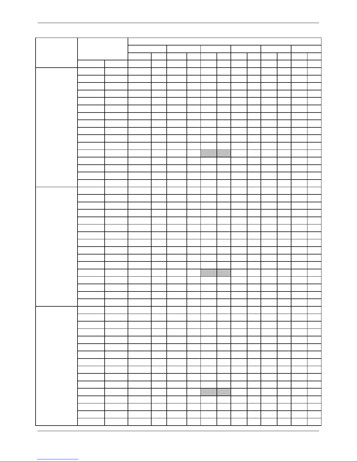
MDV-V120W/DRN1
Cooling TC: Total Capacity (kW); PI: Power Input (kW) (Compressor + Outdoor fan motor)
Combination
(%)
(Capacity
index)
Outdoor
temperature
(°C DB)
Indoor temperature(°C DB/WB)
DB:20.8,WB:1
DB:23.3,WB:1
DB:25.8,WB:1
DB:27,WB:1
DB:28.2,WB:2
DB:30.7,WB:2
DB:32,WB:2
TC
PI
TC
PI
TC
PI
TC
PI
TC
PI
TC
PI
TC
PI
kW
kW
kW
kW
kW
kW
kW
kW
kW
kW
kW
kW
kW
kW
90%
-5
7.47
0.9
8.92
1.08
10.37
1.28
11.07
1.39
11.77
1.48
13.22
1.7
14.67
1.95
-2
7.47
0.91
8.92
1.09
10.37
1.29
11.07
1.41
11.77
1.5
13.22
1.72
14.67
1.97 0 7.47
0.92
8.92
1.11
10.37
1.31
11.07
1.43
11.77
1.52
13.22
1.74
14.67
1.99 2 7.47
0.94
8.92
1.12
10.37
1.33
11.07
1.45
11.77
1.54
13.22
1.78
14.67
2.02
4
7.47
0.95
8.92
1.14
10.37
1.35
11.07
1.47
11.77
1.56
13.22
1.8
14.67
2.05
6
7.47
0.97
8.92
1.16
10.37
1.37
11.07
1.5
11.77
1.59
13.22
1.83
14.67
2.08 8 7.47
0.98
8.92
1.18
10.37
1.4
11.07
1.52
11.77
1.62
13.22
1.87
14.67
2.1
10
7.47 1 8.92
1.21
10.37
1.43
11.07
1.54
11.77
1.66
13.22
1.89
14.67
2.13
12
7.47
1.02
8.92
1.23
10.37
1.45
11.07
1.57
11.77
1.69
13.22
1.93
14.67
2.17
14
7.47
1.04
8.92
1.25
10.37
1.48
11.07
1.6
11.77
1.72
13.22
1.96
14.67
2.21
16
7.47
1.06
8.92
1.27
10.37
1.51
11.07
1.63
11.77
1.75
13.22
2
14.63
2.25
18
7.47
1.07
8.92
1.3
10.37
1.54
11.07
1.66
11.77
1.79
13.22
2.04
14.45
2.32
20
7.47
1.09
8.92
1.33
10.37
1.57
11.07
1.69
11.77
1.85
13.22
2.19
14.23
2.43
21
7.47
1.1
8.92
1.34
10.37
1.59
11.07
1.75
11.77
1.92
13.22
2.27
14.15
2.49
23
7.47
1.13
8.92
1.39
10.37
1.71
11.07
1.88
11.77
2.06
13.22
2.44
13.92
2.6
25
7.47
1.19
8.92
1.49
10.37
1.83
11.07
2.01
11.77
2.2
13.22
2.61
13.75
2.72
27
7.47
1.26
8.92
1.59
10.37
1.95
11.07
2.15
11.77
2.35
13.22
2.79
13.53
2.83
29
7.47
1.34
8.92
1.69
10.37
2.08
11.07
2.29
11.77
2.51
13.09
2.92
13.35
2.94
31
7.47
1.43
8.92
1.8
10.37
2.22
11.07
2.44
11.77
2.68
12.87
3.04
13.13
3.06
33
7.47
1.52
8.92
1.91
10.37
2.37
11.07
2.61
11.77
2.86
12.7
3.15
12.96
3.18
35
7.47
1.61
8.92
2.04
10.37
2.52
11.07
2.78
11.77
3.05
12.48
3.27
12.74
3.29
37
7.47
1.71
8.92
2.16
10.37
2.68
11.07
2.96
11.77
3.25
12.26
3.38
12.56
3.41
39
7.47
1.81
8.92
2.3
10.37
2.85
11.07
3.15
11.77
3.46
12.08
3.5
12.34
3.53
41
7.47
1.88
8.92
2.41
10.37
2.96
11.07
3.23
11.77
3.48
12
3.59
12.26
3.61
43
7.47
1.97
8.92
2.51
10.37
3.06
11.07
3.32
11.77
3.56
11.93
3.64
12.16
3.66
80%
-5
6.63
0.8
7.91
0.94
9.18
1.11
9.84
1.18
10.5
1.27
11.77
1.47
13.05
1.68
-2
6.63
0.81
7.91
0.95
9.18
1.12
9.84
1.2
10.5
1.29
11.77
1.49
13.05
1.7 0 6.63
0.82
7.91
0.96
9.18
1.14
9.84
1.22
10.5
1.31
11.77
1.51
13.05
1.72
2
6.63
0.84
7.91
0.98
9.18
1.15
9.84
1.24
10.5
1.33
11.77
1.54
13.05
1.75
4
6.63
0.85
7.91
0.99
9.18
1.17
9.84
1.27
10.5
1.36
11.77
1.57
13.05
1.78 6 6.63
0.87
7.91
1.02
9.18
1.19
9.84
1.3
10.5
1.38
11.77
1.59
13.05
1.81 8 6.63
0.88
7.91
1.04
9.18
1.22
9.84
1.32
10.5
1.41
11.77
1.61
13.05
1.84
10
6.63
0.89
7.91
1.06
9.18
1.25
9.84
1.35
10.5
1.45
11.77
1.65
13.05
1.86
12
6.63
0.9
7.91
1.08
9.18
1.27
9.84
1.38
10.5
1.48
11.77
1.68
13.05
1.9
14
6.63
0.92
7.91
1.1
9.18
1.3
9.84
1.4
10.5
1.5
11.77
1.71
13.05
1.93
16
6.63
0.93
7.91
1.12
9.18
1.32
9.84
1.42
10.5
1.53
11.77
1.75
13.05
1.97
18
6.63
0.95
7.91
1.14
9.18
1.35
9.84
1.45
10.5
1.56
11.77
1.78
13.05
2.01
20
6.63
0.97
7.91
1.17
9.18
1.38
9.84
1.48
10.5
1.59
11.77
1.85
13.05
2.15
21
6.63
0.98
7.91
1.17
9.18
1.39
9.84
1.5
10.5
1.63
11.77
1.91
13.05
2.23
23
6.63
0.99
7.91
1.2
9.18
1.45
9.84
1.59
10.5
1.74
11.77
2.05
13.05
2.39
25
6.63
1.02
7.91
1.27
9.18
1.55
9.84
1.7
10.5
1.86
11.77
2.19
13.05
2.55
27
6.63
1.09
7.91
1.36
9.18
1.66
9.84
1.82
10.5
1.98
11.77
2.34
13.05
2.73
29
6.63
1.16
7.91
1.45
9.18
1.77
9.84
1.94
10.5
2.12
11.77
2.5
13.05
2.92
31
6.63
1.23
7.91
1.54
9.18
1.88
9.84
2.06
10.5
2.26
11.77
2.67
12.83
3.04
33
6.63
1.31
7.91
1.63
9.18 2 9.84
2.2
10.5
2.4
11.77
2.85
12.65
3.15
35
6.63
1.39
7.91
1.74
9.18
2.13
9.84
2.34
10.5
2.56
11.77
3.04
12.43
3.26
37
6.63
1.47
7.91
1.84
9.18
2.26
9.84
2.49
10.5
2.73
11.77
3.24
12.26
3.38
39
6.63
1.56
7.91
1.97
9.18
2.41
9.84
2.65
10.5
2.9
11.77
3.45
12.04
3.5
41
6.63
1.59
7.91
1.98
9.18
2.44
9.84
2.72
10.5
2.96
11.77
3.53
11.96
3.56
43
6.63
1.64
7.91 2 9.18
2.48
9.84
2.77
10.5 3 11.77
3.58
11.89
3.59
Page 26

MCAC-VTSM-2016-10 R410A All DC Inverter Mini VRF
Specifications&Performance 23
MDV-V120W/DRN1
Cooling TC: Total Capacity (kW); PI: Power Input (kW) (Compressor + Outdoor fan motor)
Combination
(%)
(Capacity
index)
Outdoor
temperature
(°C DB)
Indoor temperature(°C DB/WB)
DB:20.8,WB:1
DB:23.3,WB:1
DB:25.8,WB:1
DB:27,WB:1
DB:28.2,WB:2
DB:30.7,WB:2
DB:32,WB:2
TC
PI
TC
PI
TC
PI
TC
PI
TC
PI
TC
PI
TC
PI
kW
kW
kW
kW
kW
kW
kW
kW
kW
kW
kW
kW
kW
kW
70%
-5
5.8
0.71
6.94
0.83
8.04
0.94
8.61
1.01
9.18
1.08
10.28
1.23
11.42
1.42
-2
5.8
0.72
6.94
0.84
8.04
0.95
8.61
1.03
9.18
1.1
10.28
1.25
11.42
1.44 0 5.8
0.72
6.94
0.85
8.04
0.97
8.61
1.05
9.18
1.12
10.28
1.28
11.42
1.46 2 5.8
0.72
6.94
0.85
8.04
0.98
8.61
1.07
9.18
1.14
10.28
1.31
11.42
1.48
4
5.8
0.73
6.94
0.87
8.04
1.01
8.61
1.09
9.18
1.16
10.28
1.33
11.42
1.52
6
5.8
0.74
6.94
0.89
8.04
1.03
8.61
1.12
9.18
1.19
10.28
1.35
11.42
1.55 8 5.8
0.76
6.94
0.91
8.04
1.05
8.61
1.14
9.18
1.22
10.28
1.39
11.42
1.58
10
5.8
0.77
6.94
0.93
8.04
1.08
8.61
1.17
9.18
1.25
10.28
1.42
11.42
1.59
12
5.8
0.79
6.94
0.94
8.04
1.1
8.61
1.19
9.18
1.27
10.28
1.45
11.42
1.63
14
5.8
0.81
6.94
0.96
8.04
1.12
8.61
1.2
9.18
1.29
10.28
1.47
11.42
1.66
16
5.8
0.82
6.94
0.98
8.04
1.14
8.61
1.23
9.18
1.32
10.28
1.5
11.42
1.69
18
5.8
0.83
6.94
0.99
8.04
1.17
8.61
1.25
9.18
1.34
10.28
1.53
11.42
1.72
20
5.8
0.85
6.94
1.01
8.04
1.19
8.61
1.27
9.18
1.37
10.28
1.56
11.42
1.77
21
5.8
0.85
6.94
1.02
8.04
1.2
8.61
1.29
9.18
1.38
10.28
1.58
11.42
1.83
23
5.8
0.87
6.94
1.04
8.04
1.22
8.61
1.33
9.18
1.45
10.28
1.7
11.42
1.96
25
5.8
0.88
6.94
1.08
8.04
1.3
8.61
1.42
9.18
1.55
10.28
1.81
11.42
2.1
27
5.8
0.94
6.94
1.15
8.04
1.39
8.61
1.52
9.18
1.65
10.28
1.94
11.42
2.24
29
5.8
0.99
6.94
1.22
8.04
1.48
8.61
1.62
9.18
1.76
10.28
2.06
11.42
2.4
31
5.8
1.05
6.94
1.3
8.04
1.57
8.61
1.72
9.18
1.87
10.28
2.2
11.42
2.55
33
5.8
1.12
6.94
1.38
8.04
1.67
8.61
1.83
9.18
1.99
10.28
2.34
11.42
2.72
35
5.8
1.18
6.94
1.46
8.04
1.77
8.61
1.94
9.18
2.12
10.28
2.5
11.42
2.9
37
5.8
1.25
6.94
1.55
8.04
1.89
8.61
2.06
9.18
2.26
10.28
2.66
11.42
3.09
39
5.8
1.32
6.94
1.64
8.04 2 8.61
2.19
9.18
2.4
10.28
2.83
11.42
3.29
41
5.8
1.38
6.94
1.7
8.04
2.06
8.61
2.27
9.18
2.47
10.28
2.94
11.42
3.44
43
5.8
1.49
6.94
1.82
8.04
2.14
8.61
2.39
9.18
2.54
10.28
3.05
11.42
3.55
60%
-5
4.96
0.61
5.93
0.7
6.9
0.82
7.38
0.87
7.86
0.94
8.83
1.06
9.8
1.21
-2
4.96
0.61
5.93
0.71
6.9
0.83
7.38
0.88
7.86
0.95
8.83
1.07
9.8
1.22 0 4.96
0.62
5.93
0.72
6.9
0.84
7.38
0.9
7.86
0.97
8.83
1.09
9.8
1.24
2
4.96
0.63
5.93
0.74
6.9
0.86
7.38
0.91
7.86
0.98
8.83
1.11
9.8
1.25
4
4.96
0.65
5.93
0.75
6.9
0.88
7.38
0.92
7.86
0.99
8.83
1.13
9.8
1.27 6 4.96
0.65
5.93
0.77
6.9
0.89
7.38
0.94
7.86
1.01
8.83
1.15
9.8
1.3 8 4.96
0.67
5.93
0.78
6.9
0.91
7.38
0.96
7.86
1.04
8.83
1.17
9.8
1.32
10
4.96
0.68
5.93
0.8
6.9
0.92
7.38
0.99
7.86
1.06
8.83
1.2
9.8
1.34
12
4.96
0.69
5.93
0.81
6.9
0.94
7.38
1.01
7.86
1.07
8.83
1.22
9.8
1.36
14
4.96
0.7
5.93
0.82
6.9
0.95
7.38
1.02
7.86
1.09
8.83
1.24
9.8
1.39
16
4.96
0.71
5.93
0.84
6.9
0.97
7.38
1.04
7.86
1.11
8.83
1.26
9.8
1.41
18
4.96
0.72
5.93
0.85
6.9
0.99
7.38
1.06
7.86
1.13
8.83
1.28
9.8
1.44
20
4.96
0.73
5.93
0.87
6.9
1.01
7.38
1.08
7.86
1.16
8.83
1.31
9.8
1.47
21
4.96
0.74
5.93
0.87
6.9
1.02
7.38
1.09
7.86
1.16
8.83
1.32
9.8
1.48
23
4.96
0.75
5.93
0.89
6.9
1.03
7.38
1.11
7.86
1.19
8.83
1.38
9.8
1.58
25
4.96
0.76
5.93
0.9
6.9
1.07
7.38
1.16
7.86
1.26
8.83
1.47
9.8
1.69
27
4.96
0.79
5.93
0.96
6.9
1.14
7.38
1.24
7.86
1.34
8.83
1.56
9.8
1.8
29
4.96
0.84
5.93
1.02
6.9
1.22
7.38
1.32
7.86
1.43
8.83
1.67
9.8
1.92
31
4.96
0.89
5.93
1.08
6.9
1.29
7.38
1.41
7.86
1.52
8.83
1.77
9.8
2.05
33
4.96
0.94
5.93
1.14
6.9
1.37
7.38
1.49
7.86
1.62
8.83
1.89
9.8
2.18
35
4.96
0.99
5.93
1.21
6.9
1.45
7.38
1.59
7.86
1.72
8.83
2.01
9.8
2.32
37
4.96
1.05
5.93
1.28
6.9
1.54
7.38
1.68
7.86
1.83
8.83
2.14
9.8
2.47
39
4.96
1.11
5.93
1.36
6.9
1.63
7.38
1.78
7.86
1.94
8.83
2.27
9.8
2.63
41
4.96
1.14
5.93
1.42
6.9
1.69
7.38
1.85
7.86
2.01
8.83
2.38
9.8
2.75
43
4.96
1.18
5.93
1.48
6.9
1.75
7.38
1.91
7.86
2.08
8.83
2.48
9.8
2.87
Page 27
R410A All DC Inverter Mini VRF MCAC-VTSM-2016-10
24 Specifications&Performance
MDV-V120W/DRN1
Cooling TC: Total Capacity (kW); PI: Power Input (kW) (Compressor + Outdoor fan motor)
Combination
(%)
(Capacity
index)
Outdoor
temperature
(°C DB)
Indoor temperature(°C DB/WB)
DB:20.8,WB:14
DB:23.3,WB:1
DB:25.8,WB:1
DB:27,WB:1
DB:28.2,WB:2
DB:30.7,WB:2
DB:32,WB:2
TC
PI
TC
PI
TC
PI
TC
PI
TC
PI
TC
PI
TC
PI
kW
kW
kW
kW
kW
kW
kW
kW
kW
kW
kW
kW
kW
kW
50%
-5
4.15
0.53
4.96
0.61
5.75
0.7
6.15
0.73
6.55
0.77
7.34
0.88
8.17
0.95
-2
4.15
0.53
4.96
0.62
5.75
0.71
6.15
0.74
6.55
0.79
7.34
0.89
8.17
0.96 0 4.15
0.54
4.96
0.63
5.75
0.72
6.15
0.75
6.55
0.79
7.34
0.9
8.17
0.98 2 4.15
0.55
4.96
0.64
5.75
0.73
6.15
0.76
6.55
0.81
7.34
0.91
8.17
0.99
4
4.15
0.55
4.96
0.65
5.75
0.74
6.15
0.77
6.55
0.82
7.34
0.93
8.17
1.02
6
4.15
0.56
4.96
0.66
5.75
0.75
6.15
0.79
6.55
0.84
7.34
0.95
8.17
1.05 8 4.15
0.58
4.96
0.67
5.75
0.76
6.15
0.81
6.55
0.85
7.34
0.96
8.17
1.08
10
4.15
0.59
4.96
0.68
5.75
0.78
6.15
0.82
6.55
0.88
7.34
0.99
8.17
1.1
12
4.15
0.59
4.96
0.69
5.75
0.79
6.15
0.84
6.55
0.89
7.34 1 8.17
1.12
14
4.15
0.6
4.96
0.7
5.75
0.8
6.15
0.85
6.55
0.91
7.34
1.02
8.17
1.14
16
4.15
0.61
4.96
0.71
5.75
0.81
6.15
0.87
6.55
0.92
7.34
1.04
8.17
1.16
18
4.15
0.62
4.96
0.72
5.75
0.82
6.15
0.88
6.55
0.94
7.34
1.06
8.17
1.18
20
4.15
0.63
4.96
0.73
5.75
0.84
6.15
0.89
6.55
0.95
7.34
1.07
8.17
1.2
21
4.15
0.63
4.96
0.74
5.75
0.85
6.15
0.9
6.55
0.96
7.34
1.09
8.17
1.21
23
4.15
0.64
4.96
0.74
5.75
0.86
6.15
0.92
6.55
0.98
7.34
1.1
8.17
1.24
25
4.15
0.65
4.96
0.76
5.75
0.88
6.15
0.94
6.55
1.01
7.34
1.16
8.17
1.32
27
4.15
0.66
4.96
0.79
5.75
0.92
6.15 1 6.55
1.07
7.34
1.24
8.17
1.41
29
4.15
0.7
4.96
0.83
5.75
0.98
6.15
1.06
6.55
1.14
7.34
1.31
8.17
1.5
31
4.15
0.74
4.96
0.88
5.75
1.04
6.15
1.13
6.55
1.21
7.34
1.4
8.17
1.6
33
4.15
0.78
4.96
0.93
5.75
1.1
6.15
1.19
6.55
1.29
7.34
1.48
8.17
1.7
35
4.15
0.82
4.96
0.99
5.75
1.16
6.15
1.26
6.55
1.36
7.34
1.58
8.17
1.8
37
4.15
0.87
4.96
1.04
5.75
1.24
6.15
1.34
6.55
1.45
7.34
1.67
8.17
1.92
39
4.15
0.92
4.96
1.1
5.75
1.31
6.15
1.41
6.55
1.53
7.34
1.77
8.17
2.04
41
4.15
0.95
4.96
1.15
5.75
1.35
6.15
1.48
6.55
1.6
7.34
1.87
8.17
2.13
43
4.15
1.02
4.96
1.23
5.75
1.4
6.15
1.55
6.55
1.64
7.34
1.96
8.17
2.23
Note:
1. is tested under our standard condition.
2. In cooling mode, avoid running the unit when outdoor air temperature is above 43 degrees.
3. The above table shows the average value of conditions may operate.
4. It is recommended to connect less than 130%.
Page 28
MCAC-VTSM-2016-10 R410A All DC Inverter Mini VRF
Specifications&Performance 25
MDV-V120W/DRN1
Heating TC: Total Capacity (kW); PI: Power Input (kW) (Compressor + Outdoor fan motor)
Combination (%)
(Capacity index)
Outdoor Air
temperature(°C DB)
Indoor temperature(°C WB)
16
18
20
21
22
24
TC
PI
TC
PI
TC
PI
TC
PI
TC
PI
TC
PI
°C DB
°C WB
kW
kW
kW
kW
kW
kW
kW
kW
kW
kW
kW
kW
130%
-13.7
-15
9.39
2.74
9.35
2.9
9.3
3.06
9.3
3.14
9.26
3.22
9.26
3.38
-11.8
-13
9.76
2.87
9.76
3.02
9.72
3.17
9.68
3.24
9.68
3.32
9.64
3.47
-9.8
-11
10.23
2.99
10.18
3.14
10.14
3.28
10.14
3.35
10.14
3.42
10.1
3.57
-9.5
-10
10.48
3.06
10.43
3.2
10.39
3.33
10.39
3.41
10.35
3.47
10.35
3.61
-8.5
-9.1
10.68
3.11
10.64
3.24
10.64
3.38
10.6
3.45
10.6
3.52
10.56
3.66
-7
-7.6
11.06
3.2
11.06
3.33
11.02
3.47
11.02
3.53
10.98
3.6
10.94
3.73
-5
-5.6
11.65
3.32
11.61
3.45
11.56
3.57
11.56
3.64
11.52
3.7
11.52
3.82
-3
-3.7
12.19
3.43
12.15
3.55
12.15
3.67
12.11
3.73
12.11
3.79
12.07
3.91
0
-0.7
13.16
3.6
13.16
3.71
13.12
3.82
13.12
3.86
13.07
3.93
13.07
4.04 3 2.2
14.2
3.74
14.16
3.85
14.12
3.95
14.12 4 14.12
4.06
14.08
4.16
5
4.1
14.92
3.84
14.88
3.94
14.88
4.03
14.83
4.08
14.83
4.13
14.79
4.23
7 6 15.67
3.93
15.63
4.02
15.63
4.11
15.59
4.16
15.59
4.2
14.96
4.04 9 7.9
16.47
4.01
16.43
4.1
16.43
4.19
16.39
4.23
16.05
4.14
14.96
3.79
11
9.8
17.31
4.09
17.27
4.17
17.18
4.23
16.59
4.06
16.05
3.89
14.96
3.57
13
11.8
18.23
4.17
18.19
4.25
17.18
3.96
16.59
3.8
16.05
3.65
14.96
3.35
15
13.7
19.11
4.24
18.27
4.02
17.18
3.73
16.59
3.59
16.05
3.44
14.96
3.16
120%
-13.7
-15
9.35
2.96
9.3
3.1
9.26
3.24
9.26
3.32
9.26
3.39
9.22
3.54
-11.8
-13
9.72
3.07
9.72
3.21
9.68
3.35
9.68
3.42
9.64
3.49
9.64
3.63
-9.8
-11
10.18
3.19
10.14
3.32
10.14
3.45
10.1
3.52
10.1
3.58
10.06
3.72
-9.5
-10
10.44
3.24
10.39
3.38
10.35
3.5
10.35
3.57
10.35
3.63
10.31
3.76
-8.5
-9.1
10.64
3.29
10.6
3.42
10.6
3.55
10.56
3.61
10.56
3.68
10.52
3.8
-7
-7.6
11.02
3.38
11.02
3.5
10.98
3.62
10.98
3.69
10.94
3.75
10.94
3.87
-5
-5.6
11.61
3.49
11.57
3.61
11.52
3.72
11.52
3.78
11.52
3.84
11.48
3.95
-3
-3.7
12.15
3.59
12.15
3.7
12.11
3.81
12.11
3.87
12.07
3.93
12.07
4.03 0 -0.7
13.12
3.75
13.12
3.85
13.07
3.95
13.07 4 13.03
4.05
13.03
4.16
3
2.2
14.16
3.88
14.12
3.98
14.12
4.07
14.08
4.12
14.08
4.17
13.79
4.15
5
4.1
14.88
3.97
14.83
4.06
14.83
4.15
14.79
4.2
14.79
4.24
13.79
3.89 7 6
15.63
4.05
15.63
4.14
15.59
4.22
15.34
4.16
14.83
3.99
13.79
3.66
9
7.9
16.43
4.13
16.39
4.21
15.84
4.07
15.34
3.91
14.83
3.75
13.79
3.45
11
9.8
17.27
4.2
16.85
4.13
15.84
3.83
15.34
3.68
14.83
3.53
13.79
3.25
13
11.8
17.89
4.16
16.85
3.88
15.84
3.59
15.34
3.46
14.83
3.32
13.79
3.06
15
13.7
17.89
3.92
16.85
3.65
15.84
3.39
15.34
3.26
14.83
3.13
13.79
2.88
110%
-13.7
-15
9.3
3.17
9.26
3.3
9.22
3.43
9.22
3.5
9.22
3.57
9.18
3.7
-11.8
-13
9.68
3.28
9.68
3.4
9.64
3.53
9.64
3.59
9.6
3.66
9.6
3.79
-9.8
-11
10.14
3.38
10.1
3.5
10.1
3.62
10.06
3.69
10.06
3.74
10.06
3.87
-9.5
-10
10.39
3.43
10.35
3.55
10.31
3.67
10.31
3.73
10.31
3.79
10.27
3.91
-8.5
-9.1
10.6
3.48
10.56
3.6
10.56
3.71
10.52
3.77
10.52
3.83
10.52
3.49
-7
-7.6
10.98
3.56
10.98
3.67
10.94
3.78
10.94
3.84
10.94
3.89
10.9
4.01
-5
-5.6
11.57
3.66
11.52
3.77
11.48
3.87
11.48
3.93
11.48
3.98
11.44
4.09
-3
-3.7
12.11
3.75
12.11
3.85
12.07
3.96
12.07
4.01
12.03
4.06
12.03
4.16
0
-0.7
13.07
3.89
13.07
3.99
13.03
4.08
13.03
4.13
13.03
4.18
12.66
4.1
3
2.2
14.12
4.02
14.08
4.11
14.08
4.2
14.04
4.24
13.58
4.07
12.66
3.73 5 4.1
14.83
4.1
14.83
4.19
14.54
4.15
14.04
3.98
13.58
3.82
12.66
3.51
7 6 15.59
4.18
15.46
4.2
14.54
3.89
14.04
3.74
13.58
3.59
12.66
3.3
9
7.9
16.38
4.25
15.46
3.95
14.54
3.66
14.04
3.52
13.58
3.38
12.66
3.11
11
9.8
16.38
3.99
15.46
3.72
14.54
3.45
14.04
3.32
13.58
3.19
12.66
2.93
13
11.8
16.38
3.74
15.46
3.49
14.54
3.24
14.04
3.12
13.58 3 12.66
2.76
15
13.7
16.38
3.33
15.46
3.29
14.54
3.06
14.04
2.94
13.58
2.83
12.66
2.61
Page 29

R410A All DC Inverter Mini VRF MCAC-VTSM-2016-10
26 Specifications&Performance
MDV-V120W/DRN1
Heating TC: Total Capacity (kW); PI: Power Input (kW) (Compressor + Outdoor fan motor)
Combination (%)
(Capacity index)
Outdoor Air
temperature(°C DB)
Indoor temperature(°C WB)
16
18
20
21
22
24
TC
PI
TC
PI
TC
PI
TC
PI
TC
PI
TC
PI
°C DB
°C WB
kW
kW
kW
kW
kW
kW
kW
kW
kW
kW
kW
kW
100%
-13.7
-15
9.26
3.38
9.22
3.5
9.18
3.62
9.18
3.69
9.18
3.74
9.14
3.87
-11.8
-13
9.64
3.48
9.64
3.59
9.6
3.71
9.6
3.77
9.6
3.83
9.55
3.94
-9.8
-11
10.1
3.57
10.06
3.69
10.06
3.79
10.06
3.85
10.01
3.91
10.01
4.02
-9.5
-10
10.35
3.62
10.31
3.73
10.31
3.84
10.27
3.89
10.27
3.95
10.22
4.06
-8.5
-9.1
10.56
3.66
10.52
3.77
10.52
3.88
10.52
3.93
10.48
3.98
10.48
4.09
-7
-7.6
10.94
3.74
10.94
3.84
10.9
3.94
10.9
3.99
10.9
4.04
10.85
4.15
-5
-5.6
11.52
3.83
11.48
3.93
11.48
4.02
11.44
4.07
11.44
4.12
11.4
4.22
-3
-3.7
12.07
3.92
12.07
3.56
12.03
4.1
12.03
4.15
12.03
4.19
11.52
4.02
0
-0.7
13.03
4.04
13.03
4.13
12.99
4.21
12.78
4.15
12.36
3.97
11.52
3.65
3
2.2
14.08
4.16
14.04
4.24
13.2
3.92
12.78
3.77
12.36
3.62
11.52
3.32 5 4.1
14.79
4.24
14.04
3.98
13.2
3.69
12.78
3.55
12.36
3.41
11.52
3.13
7 6 14.88
4.02
14.04
3.74
13.2
3.47
12.78
3.34
12.36
3.21
11.52
2.95
9
7.9
14.88
3.78
14.04
3.52
13.2
3.27
12.78
3.1
12.36
3.02
11.52
2.79
11
9.8
14.88
3.56
14.04
3.32
13.2
3.08
12.78
2.97
12.36
2.85
11.52
2.63
13
11.8
14.88
3.34
14.04
3.12
13.2
2.9
12.78
2.79
12.36
2.69
11.52
2.48
15
13.7
14.88
3.15
14.04
2.94
13.2
2.74
12.78
2.64
12.36
2.54
11.52
2.35
90%
-13.7
-15
9.2
3.6
9.16
3.7
9.16
3.81
9.12
3.87
9.12
3.92
9.12
4.03
-11.8
-13
9.58
3.68
9.58
3.79
9.54
3.89
9.54
3.94
9.54
3.99
9.5
4.1
-9.8
-11
10.04
3.77
10.04
3.87
10
3.97
10
4.02
10
4.07
9.96
4.17
-9.5
-10
10.29
3.81
10.25
3.91
10.25
4.01
10.21
4.06
10.21
4.11
10.21
4.2
-8.5
-9.1
10.5
3.85
10.5
3.95
10.46
4.04
10.46
4.09
10.46
4.14
10.33
4.18
-7
-7.6
10.88
3.92
10.88
4.01
10.83
4.1
10.83
4.15
10.83
4.19
10.33
3.99
-5
-5.6
11.46
4
11.42
4.09
11.42
4.17
11.38
4.22
11.09
4.09
10.33
3.75
-3
-3.7
12.01
4.08
12.01
4.16
11.88
4.18
11.46
4.01
11.09
3.85
10.33
3.53
0
-0.7
13.01
4.2
12.63
4.09
11.88
3.79
11.46
3.64
11.09
3.5
10.33
3.21 3 2.2
13.39
4
12.63
3.72
11.88
3.45
11.46
3.32
11.09
3.19
10.33
2.94 5 4.1
13.39
3.76
12.63
3.5
11.88
3.25
11.46
3.13
11.09
3.01
10.33
2.77 7 6
13.39
3.53
12.63
3.3
11.88
3.06
11.46
2.95
11.09
2.84
10.33
2.62 9 7.9
13.39
3.33
12.63
3.1
11.88
2.89
11.46
2.78
11.09
2.68
10.33
2.47
11
9.8
13.39
3.14
12.63
2.93
11.88
2.73
11.46
2.63
11.09
2.53
10.33
2.34
13
11.8
13.39
2.95
12.63
2.76
11.88
2.57
11.46
2.48
11.09
2.39
10.33
2.21
15
13.7
13.39
2.79
12.63
2.61
11.88
2.44
11.46
2.35
11.09
2.27
10.33
2.1
80%
-13.7
-15
9.18
3.81
9.14
3.9
9.14 4 9.14
4.05
9.09
4.1
9.09
4.2
-11.8
-13
9.55
3.88
9.55
3.98
9.51
4.07
9.51
4.11
9.51
4.16
9.22
4.05
-9.8
-11
10.02
3.96
10.02
4.05
9.97
4.14
9.97
4.18
9.89
4.17
9.22
3.83
-9.5
-10
10.27
4
10.22
4.09
10.23
4.17
10.23
4.22
9.89
4.05
9.22
3.71
-8.5
-9.1
10.48
4.04
9.74
4.12
10.43
4.2
10.23
4.11
9.89
3.94
9.22
3.61
-7
-7.6
10.85
4.1
10.85
4.18
10.56
4.09
10.23
3.92
9.89
3.77
9.22
3.46
-5
-5.6
11.44
4.17
11.23
4.15
10.56
3.84
10.23
3.69
9.89
3.54
9.22
3.25
-3
-3.7
11.9
4.19
11.23
3.9
10.56
3.61
10.23
3.48
9.89
3.34
9.22
3.07 0 -0.7
11.9
3.8
11.23
3.54
10.56
3.29
10.23
3.17
9.89
3.04
9.22
2.8 3 2.2
11.9
3.47
11.23
3.23
10.56
3.01
10.23
2.89
9.89
2.78
9.22
2.57 5 4.1
11.9
3.26
11.23
3.05
10.56
2.83
10.23
2.73
9.89
2.63
9.22
2.43 7 6
11.9
3.07
11.23
2.88
10.56
2.68
10.23
2.58
9.89
2.49
9.22
2.3
9
7.9
11.9
2.9
11.23
2.71
10.56
2.53
10.23
2.44
9.89
2.35
9.22
2.18
11
9.8
11.9
2.74
11.23
2.56
10.56
2.39
10.23
2.31
9.89
2.23
9.22
2.06
13
11.8
11.9
2.58
11.23
2.42
10.56
2.26
10.23
2.18
9.89
2.1
9.22
1.95
15
13.7
11.9
2.44
11.23
2.29
10.56
2.14
10.23
2.07
9.89 2 9.22
1.86
Page 30
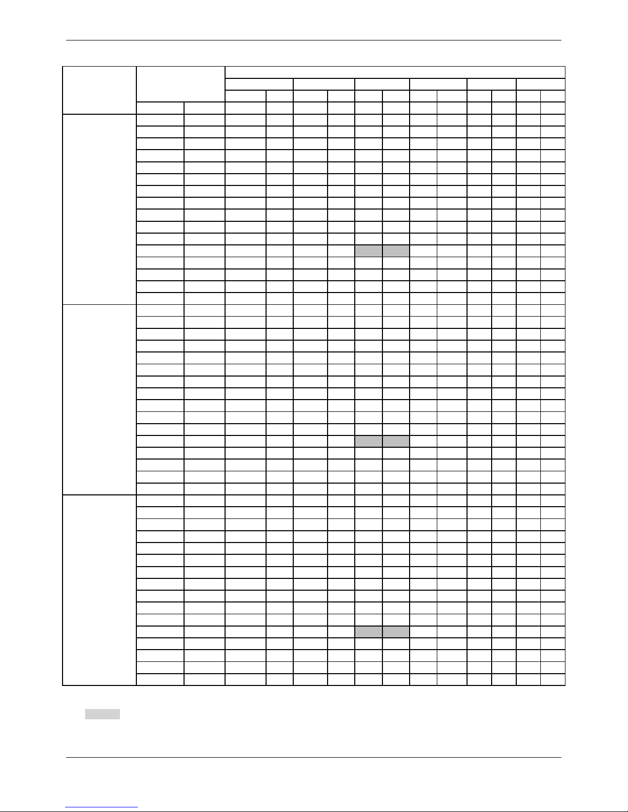
MCAC-VTSM-2016-10 R410A All DC Inverter Mini VRF
Specifications&Performance 27
MDV-V120W/DRN1
Heating TC: Total Capacity (kW); PI: Power Input (kW) (Compressor + Outdoor fan motor)
Combination (%)
(Capacity index)
Outdoor Air
temperature(°C DB)
Indoor temperature(°C WB)
16
18
20
21
22
24
TC
PI
TC
PI
TC
PI
TC
PI
TC
PI
TC
PI
°C DB
°C WB
kW
kW
kW
kW
kW
kW
kW
kW
kW
kW
kW
kW
70%
-13.7
-15
9.11
4.02
9.07
4.11
9.07
4.19
8.91
4.13
8.61
3.96
8.03
3.63
-11.8
-13
9.49
4.09
9.49
4.17
9.24
4.07
8.91
3.91
8.61
3.75
8.03
3.44
-9.8
-11
9.95
4.15
9.82
4.15
9.24
3.84
8.91
3.7
8.61
3.55
8.03
3.26
-9.5
-10
10.2
4.19
9.82
4.03
9.24
3.73
8.91
3.59
8.61
3.45
8.03
3.17
-8.5
-9.1
10.41
4.21
9.82
3.92
9.24
3.63
8.91
3.49
8.61
3.36
8.03
3.09
-7
-7.6
10.41
4.02
9.82
3.74
9.24
3.47
8.91
3.34
8.61
3.21
8.03
2.96
-5
-5.6
10.41
3.78
9.82
3.52
9.24
3.27
8.91
3.15
8.61
3.72
8.03
2.79
-3
-3.7
10.41
3.56
9.82
3.32
9.24
3.09
8.91
2.97
8.61
2.86
8.03
2.64 0 -0.7
10.41
3.24
9.82
3.03
9.24
2.82
8.91
2.71
8.61
2.61
8.03
2.42 3 2.2
10.41
2.96
9.82
2.77
9.24
2.58
8.91
2.49
8.61
2.4
8.03
2.22 5 4.1
10.41
2.79
9.82
2.61
9.24
2.44
8.91
2.35
8.61
2.27
8.03
2.1 7 6
10.41
2.64
9.82
2.47
9.24
2.31
8.91
2.23
8.61
2.15
8.03
1.99 9 7.9
10.41
2.5
9.82
2.34
9.24
2.19
8.91
2.11
8.61
2.04
8.03
1.89
11
9.8
10.41
2.36
9.82
2.21
9.24
2.07
8.91 2 8.61
1.93
8.03
1.79
13
11.8
10.41
2.23
9.82
2.1
9.24
1.96
8.91
1.9
8.61
1.83
8.03
1.7
15
13.7
10.41
2.11
9.82
1.99
9.24
1.86
8.91
1.8
8.61
1.74
8.03
1.62
60%
-13.7
-15
8.93
4.13
8.42
3.84
7.92
3.56
7.67
3.42
7.42
3.29
6.91
3.02
-11.8
-13
8.93
3.91
8.42
3.64
7.92
3.38
7.67
3.25
7.42
3.12
6.91
2.89
-9.8
-11
8.93
3.69
8.42
3.44
7.92
3.19
7.67
3.07
7.42
2.96
6.91
2.73
-9.5
-10
8.93
3.59
8.42
3.34
7.92
3.1
7.67
2.99
7.42
2.87
6.91
2.65
-8.5
-9.1
8.93
3.49
8.42
3.26
7.92
3.03
7.67
2.92
7.42
2.8
6.91
2.59
-7
-7.6
8.93
3.34
8.42
3.12
7.92
2.9
7.67
2.79
7.42
2.69
6.91
2.48
-5
-5.6
8.93
3.15
8.42
2.94
7.92
2.74
7.67
2.64
7.42
2.54
6.91
2.35
-3
-3.7
8.93
2.97
8.42
2.78
7.92
2.59
7.67
2.5
7.42
2.4
6.91
2.22 0 -0.7
8.93
2.71
8.42
2.54
7.92
2.37
7.67
2.29
7.42
2.2
6.91
2.04
3
2.2
8.93
2.49
8.42
2.33
7.92
2.18
7.67
2.1
7.42
2.03
6.91
1.88 5 4.1
8.93
2.35
8.42
2.21
7.92
2.06
7.67 2 7.42
1.92
6.91
1.79 7 6
8.93
2.23
8.42
2.09
7.92
1.96
7.67
1.89
7.42
1.83
6.91
1.7
9
7.9
8.93
2.11
8.42
1.98
7.92
1.86
7.67
1.8
7.42
1.73
6.91
1.62
11
9.8
8.93 2 8.42
1.88
7.92
1.77
7.67
1.71
7.42
1.65
6.91
1.54
13
11.8
8.93
1.89
8.42
1.78
7.92
1.68
7.67
1.62
7.42
1.57
6.91
1.46
15
13.7
8.93
1.8
8.42
1.69
7.92
1.6
7.67
1.55
7.42
1.5
6.91
1.4
50%
-13.7
-15
7.44
3.31
7.02
3.09
6.6
2.87
6.35
2.77
6.14
2.66
5.72
2.46
-11.8
-13
7.44
3.14
7.02
2.93
6.6
2.73
6.35
2.63
6.14
2.53
5.72
2.34
-9.8
-11
7.44
2.97
7.02
2.78
6.6
2.59
6.35
2.5
6.14
2.41
5.72
2.23
-9.5
-10
7.44
2.89
7.02
2.7
6.6
2.52
6.35
2.43
6.14
2.34
5.72
2.17
-8.5
-9.1
7.44
2.82
7.02
2.64
6.6
2.46
6.35
2.37
6.14
2.29
5.72
2.12
-7
-7.6
7.44
2.7
7.02
2.53
6.6
2.36
6.35
2.28
6.14
2.2
5.72
2.04
-5
-5.6
7.44
2.55
7.02
2.39
6.6
2.24
6.35
2.16
6.14
2.08
5.72
1.93
-3
-3.7
7.44
2.42
7.02
2.27
6.6
2.12
6.35
2.05
6.14
1.97
5.72
1.83
0
-0.7
7.44
2.22
7.02
2.08
6.6
1.95
6.35
1.88
6.14
1.82
5.72
1.69 3 2.2
7.44
2.04
7.02
1.92
6.6
1.8
6.35
1.74
6.14
1.68
5.72
1.57 5 4.1
7.44
1.94
7.02
1.82
6.6
1.71
6.35
1.65
6.14
1.6
5.72
1.49 7 6
7.44
1.84
7.02
1.73
6.6
1.63
6.35
1.57
6.14
1.52
5.72
1.42 9 7.9
7.44
1.74
7.02
1.64
6.6
1.55
6.35
1.5
6.14
1.45
5.72
1.36
11
9.8
7.44
1.66
7.02
1.56
6.6
1.47
6.35
1.43
6.14
1.38
5.72
1.29
13
11.8
7.44
1.58
7.02
1.49
6.6
1.4
6.35
1.36
6.14
1.32
5.72
1.23
15
13.7
7.44
1.5
7.02
1.42
6.6
1.34
6.35
1.3
6.14
1.26
5.72
1.18
Note:
1. is tested under our standard condition.
2. In heating mode, avoid running the unit when the outdoor air temperature is below -15 degrees.
3. The above table shows the average value of conditions may operate.
4. It is recommended to connect less than 130%.
Page 31

R410A All DC Inverter Mini VRF MCAC-VTSM-2016-10
28 Specifications&Performance
MDV-V140W/DRN1
Cooling TC: Total Capacity (kW); PI: Power Input (kW) (Compressor + Outdoor fan motor)
Combination
(%)
(Capacity
index)
Outdoor
temperature
(°C DB)
Indoor temperature(°C DB/WB)
DB:20.8,WB:14
DB:23.3,WB:16
DB:25.8,WB:18
DB:27,WB:19
DB:28.2,WB:20
DB:30.7,WB:22
DB:32,WB:24
TC
PI
TC
PI
TC
PI
TC
PI
TC
PI
TC
PI
TC
PI
kW
kW
kW
kW
kW
kW
kW
kW
kW
kW
kW
kW
kW
kW
130%
-5
12.3
1.61
14.65
1.97
17
2.11
17.65
2.2
18.5
2.26
18.95
2.46
19.43
2.47
-2
12.3
1.61
14.65
2.01
17
2.11
17.65
2.21
18.5
2.26
18.95
2.49
19.43
2.5 0 12.3
1.64
14.65
2.04
17
2.19
17.65
2.33
18.5
2.39
18.95
2.52
19.43
2.53 2 12.3
1.67
14.65
2.05
17
2.26
17.65
2.46
18.5
2.42
18.95
2.54
19.43
2.57
4
12.3
1.71
14.65
2.09
17
2.34
17.65
2.47
18.5
2.45
18.95
2.54
19.43
2.62
6
12.3
1.74
14.65
2.13
17
2.43
17.65
2.5
18.29
2.53
18.72
2.54
19.21
2.64 8 12.3
1.78
14.65
2.18
17
2.55
17.65
2.62
18.07
2.61
18.51
3.9
18.97
2.66
10
12.3
1.82
14.65
2.23
17
2.65
17.65
2.7
17.85
4.04
18.3
4.06
18.75
2.74
12
12.3
1.85
14.65
2.27
17
2.7
17.4
4.03
17.65
4.06
18.05
4.07
18.5
2.76
14
12.3
1.89
14.65
2.31
16.95
4.05
17.2
4.06
17.4
4.08
17.85
4.09
18.3
2.82
16
12.3
1.92
14.65
2.36
16.75
4.06
16.95
4.08
17.15
4.1
17.6
4.12
18.05
2.86
18
12.3
1.96
14.65
2.41
16.5
2.82
16.7
2.84
16.95
2.85
17.4
2.88
17.85
2.91
20
12.3 2 14.65
2.56
16.25
2.96
16.5
2.98
16.7
2.99
17.15
3.02
17.6
3.05
21
12.3
2.05
14.65
2.65
16.15
3.03
16.4
3.05
16.6
3.06
17.05
3.09
17.5
3.12
23
12.3
2.2
14.65
2.84
15.95
3.17
16.15
3.18
16.35
3.2
16.8
3.23
17.25
3.26
25
12.3
2.35
14.65
3.05
15.7
3.31
15.9
3.32
16.15
3.34
16.6
3.38
17.05
3.41
27
12.3
2.51
14.65
3.26
15.5
3.44
15.7
3.47
15.9
3.48
16.35
3.52
16.8
3.56
29
12.3
2.68
14.65
3.48
15.25
3.58
15.45
3.6
15.7
3.63
16.15
3.66
16.6
3.7
31
12.3
2.86
14.6
3.68
15
3.73
15.25
3.75
15.45
3.76
15.9
3.81
16.35
3.85
33
12.3
3.05
14.35
3.82
14.8
3.86
15
3.89
15.25
3.91
15.7
3.95
16.1
3.99
35
12.3
3.25
14.1
3.96
14.55
4.01
14.8
4.03
15
4.05
15.45
4.1
15.9
4.14
37
12.3
3.46
13.9
4.1
14.35
4.15
14.55
4.17
14.8
4.2
15.2
4.25
15.65
4.3
39
12.3
3.68
13.65
4.15
14.1
4.29
14.35
4.32
14.55
4.34
15
4.39
15.45
4.45
41
12.3
3.88
13.51
4.19
13.95
4.33
14.2
4.36
14.4
4.38
14.85
4.4
14.86
4.49
43
12.3
3.98
13.41
4.21
13.88
4.34
14.13
4.38
14.25
4.39
14.58
4.41
14.68
4.5
120%
-5
11.35
1.56
13.5
1.89
15.7
2.23
16.8
2.44
17.6
2.54
18
2.62
18.4
2.69
-2
11.35
1.57
13.5
1.91
15.7
2.26
16.8
2.45
17.6
2.57
18
2.64
18.4
2.7 0 11.35
1.59
13.5
1.92
15.7
2.28
16.8
2.46
17.6
2.59
18
2.66
18.4
2.71
2
11.35
1.59
13.5
1.94
15.7
2.3
16.8
2.48
17.6
2.6
18
2.68
18.4
2.71
4
11.35
1.61
13.5
1.97
15.7
2.33
16.8
2.5
17.6
2.64
18
2.68
18.4
2.72 6 11.35
1.63
13.5
1.98
15.7
2.36
16.8
2.53
17.6
2.67
18
2.71
18.4
2.73 8 11.35
1.64
13.5 2 15.7
2.39
16.8
2.56
17.6
2.69
18
2.71
18.4
2.74
10
11.35
1.66
13.5
2.03
15.7
2.41
16.8
2.61
17.6
2.69
18
2.72
18.4
2.75
12
11.35
1.69
13.5
2.07
15.7
2.46
16.8
2.66
17.35
2.71
17.75
2.71
18.15
2.77
14
11.35
1.73
13.5
2.11
15.7
2.51
16.8
2.71
17.1
2.72
17.55
2.75
17.95
2.8
16
11.35
1.76
13.5
2.15
15.7
2.56
16.7
4.1
16.9
2.76
17.3
2.79
17.7
2.84
18
11.35
1.79
13.5
2.19
15.7
2.64
16.45
2.82
16.65
2.83
17.05
2.86
17.5
2.89
20
11.35
1.83
13.5
2.28
15.7
2.84
16.25
2.96
16.45
2.97
16.85
3
17.25
3.02
21
11.35
1.84
13.5
2.36
15.7
2.94
16.1
3.03
16.3
3.04
16.75
3.07
17.15
3.1
23
11.35
1.97
13.5
2.53
15.7
3.15
15.9
3.16
16.1
3.18
16.5
3.21
16.9
3.24
25
11.35
2.1
13.5
2.7
15.45
3.29
15.65
3.3
15.85
3.32
16.3
3.35
16.7
3.38
27
11.35
2.25
13.5
2.89
15.25
3.42
15.45
3.44
15.65
3.46
16.05
3.49
16.45
3.52
29
11.35
2.4
13.5
3.09
15
3.56
15.2
3.58
15.4
3.6
15.8
3.64
16.25
3.67
31
11.35
2.56
13.5
3.3
14.75
3.71
15
3.72
15.2
3.74
15.6
3.78
16
3.82
33
11.35
2.72
13.5
3.51
14.55
3.84
14.75
3.86
14.95
3.88
15.35
3.92
15.75
3.96
35
11.35
2.9
13.5
3.75
14.3
3.98
14.5 4 14.75
4.02
15.15
4.07
15.55
4.11
37
11.35
3.08
13.5
3.99
14.1
4.13
14.3
4.15
14.5
4.17
14.9
4.21
15.3
4.26
39
11.35
3.28
13.45
4.22
13.85
4.26
14.05
4.29
14.25
4.31
14.7
4.36
15.1
4.4
41
11.35
3.37
13.34
4.25
13.74
4.29
13.94
4.32
14.14
4.34
14.59
4.37
14.67
4.44
43
11.35
3.42
13.27
4.28
13.63
4.32
13.83
4.34
14.03
4.36
14.34
4.38
14.44
4.52
Page 32

MCAC-VTSM-2016-10 R410A All DC Inverter Mini VRF
Specifications&Performance 29
MDV-V140W/DRN1
Cooling TC: Total Capacity (kW); PI: Power Input (kW) (Compressor + Outdoor fan motor)
Combination
(%)
(Capacity
index)
Outdoor
temperature
(°C DB)
Indoor temperature(°C DB/WB)
DB:20.8,WB:
DB:23.3,WB:1
DB:25.8,WB:1
DB:27,WB:19
DB:28.2,WB:2
DB:30.7,WB:2
DB:32,WB:24
TC
PI
TC
PI
TC
PI
TC
PI
TC
PI
TC
PI
TC
PI
kW
kW
kW
kW
kW
kW
kW
kW
kW
kW
kW
kW
kW
kW
110%
-5
10.4
1.36
12.4
1.7
14.4
2.02
15.4
2.17
16.4
2.34
17.65
2.43
18.05
2.5
-2
10.4
1.39
12.4
1.72
14.4
2.04
15.4
2.19
16.4
2.35
17.65
2.45
18.05
2.51 0 10.4
1.4
12.4
1.73
14.4
2.06
15.4
2.21
16.4
2.38
17.65
2.47
18.05
2.55 2 10.4
1.43
12.4
1.74
14.4
2.09
15.4
2.23
16.4
2.41
17.65
2.51
18.05
2.58
4
10.4
1.46
12.4
1.76
14.4
2.11
15.4
2.26
16.4
2.44
17.65
2.55
18.05
2.6
6
10.4
1.48
12.4
1.78
14.4
2.13
15.4
2.29
16.4
2.47
17.65
2.57
18.05
2.64 8 10.4
1.49
12.4
1.81
14.4
2.15
15.4
2.32
16.4
2.5
17.65
2.59
18.05
2.67
10
10.4
1.51
12.4
1.84
14.4
2.18
15.4
2.36
16.4
2.54
17.65
2.61
18.05
2.69
12
10.4
1.54
12.4
1.87
14.4
2.23
15.4
2.41
16.4
2.59
17.45
2.65
17.8
2.73
14
10.4
1.57
12.4
1.91
14.4
2.27
15.4
2.45
16.4
2.64
17.2
2.67
17.6
2.75
16
10.4
1.59
12.4
1.94
14.4
2.31
15.4
2.5
16.4
2.69
17
2.7
17.35
2.78
18
10.4
1.62
12.4
1.98
14.4
2.36
15.4
2.57
16.4
2.82
16.75
2.84
17.15
2.86
20
10.4
1.66
12.4
2.02
14.4
2.5
15.4
2.76
16.15
2.95
16.55
2.98
16.9
3
21
10.4
1.67
12.4
2.08
14.4
2.59
15.4
2.86
16.05
3.02
16.4
3.05
16.8
3.07
23
10.4
1.75
12.4
2.23
14.4
2.77
15.4
3.07
15.8
3.16
16.2
3.19
16.55
3.22
25
10.4
1.87
12.4
2.38
14.4
2.97
15.4
3.28
15.6
3.3
15.95
3.33
16.35
3.35
27
10.4
1.99
12.4
2.55
14.4
3.17
15.15
3.42
15.35
3.43
15.75
3.47
16.1
3.5
29
10.4
2.12
12.4
2.72
14.4
3.39
14.95
3.56
15.15
3.58
15.5
3.61
15.9
3.64
31
10.4
2.26
12.4
2.9
14.4
3.62
14.7
3.7
14.9
3.72
15.3
3.75
15.65
3.79
33
10.4
2.41
12.4
3.09
14.3
3.82
14.5
3.84
14.7
3.85
15.05
3.89
15.45
3.93
35
10.4
2.56
12.4
3.3
14.05
3.96
14.25
3.98
14.45 4 14.8
4.04
15.2
4.07
37
10.4
2.73
12.4
3.51
13.85
4.1
14.05
4.12
14.2
4.14
14.6
4.18
14.95
4.22
39
10.4
2.9
12.4
3.74
13.6
4.24
13.8
4.26
14
4.28
14.35
4.32
14.75
4.37
41
10.4
2.93
12.4
3.77
13.49
4.27
13.69
4.29
13.89
4.31
14.17
4.35
14.31
4.4
43
10.4
2.96
12.4
3.82
13.39
4.3
13.59
4.32
13.79
4.34
14.04
4.37
14.09
4.48
100%
-5
9.45
1.24
11.25
1.49
13.1
1.78
14
1.9
14.9
2.07
16.75
2.35
17.7
2.46
-2
9.45
1.26
11.25
1.51
13.1
1.8
14
1.94
14.9
2.09
16.75
2.38
17.7
2.47 0 9.45
1.27
11.25
1.53
13.1
1.82
14
1.96
14.9
2.11
16.75
2.42
17.7
2.5
2
9.45
1.29
11.25
1.55
13.1
1.84
14
1.99
14.9
2.14
16.75
2.46
17.7
2.54
4
9.45
1.3
11.25
1.56
13.1
1.86
14
2.02
14.9
2.16
16.75
2.48
17.7
2.57 6 9.45
1.32
11.25
1.6
13.1
1.89
14
2.05
14.9
2.2
16.75
2.52
17.7
2.61 8 9.45
1.35
11.25
1.62
13.1
1.92
14
2.08
14.9
2.23
16.75
2.56
17.7
2.65
10
9.45
1.36
11.25
1.65
13.1
1.95
14
2.11
14.9
2.27
16.75
2.6
17.7
2.69
12
9.45
1.38
11.25
1.68
13.1
1.99
14
2.15
14.9
2.32
16.75
2.65
17.45
2.71
14
9.45
1.41
11.25
1.71
13.1
2.03
14
2.19
14.9
2.36
16.75
2.7
17.25
2.74
16
9.45
1.44
11.25
1.75
13.1
2.07
14
2.24
14.9
2.41
16.65
2.73
17
2.77
18
9.45
1.46
11.25
1.78
13.1
2.11
14
2.28
14.9
2.45
16.45
2.82
16.8
2.84
20
9.45
1.49
11.25
1.82
13.1
2.17
14
2.4
14.9
2.63
16.2
2.95
16.55
2.98
21
9.45
1.51
11.25
1.83
13.1
2.25
14
2.48
14.9
2.72
16.1
3.02
16.45
3.05
23
9.45
1.54
11.25
1.95
13.1
2.41
14
2.66
14.9
2.92
15.9
3.16
16.2
3.19
25
9.45
1.64
11.25
2.09
13.1
2.58
14
2.85
14.9
3.12
15.65
3.3
16
3.33
27
9.45
1.76
11.25
2.23
13.1
2.76
14
3.05
14.9
3.34
15.4
3.44
15.75
3.47
29
9.45
1.87
11.25
2.37
13.1
2.94
14
3.25
14.85
3.55
15.2
3.58
15.55
3.61
31
9.45
1.99
11.25
2.53
13.1
3.14
14
3.47
14.65
3.69
14.95
3.72
15.3
3.75
33
9.45
2.11
11.25
2.7
13.1
3.35
14
3.71
14.4
3.83
14.75
3.86
15.1
3.9
35
9.45
2.25
11.25
2.87
13.1
3.57
14
3.95
14.15
3.97
14.5 4 14.85
4.04
37
9.45
2.39
11.25
3.06
13.1
3.81
13.75
4.09
13.95
4.11
14.3
4.15
14.6
4.18
39
9.45
2.54
11.25
3.25
13.1
4.05
13.55
4.23
13.7
4.25
14.05
4.29
14.4
4.33
41
9.45
2.66
11.25
3.37
13.1
4.2
13.34
4.26
13.59
4.31
13.81
4.39
14.19
4.42
43
9.45
2.78
11.25
3.48
13.1
4.28
13.13
4.31
13.5
4.36
13.89
4.41
13.94
4.47
Page 33

R410A All DC Inverter Mini VRF MCAC-VTSM-2016-10
30 Specifications&Performance
MDV-V140W/DRN1
Cooling TC: Total Capacity (kW); PI: Power Input (kW) (Compressor + Outdoor fan motor)
Combination
(%)
(Capacity
index)
Outdoor
temperature
(°C DB)
Indoor temperature(°C DB/WB)
DB:20.8,WB:
DB:23.3,WB:1
DB:25.8,WB:1
DB:27,WB:1
DB:28.2,WB:2
DB:30.7,WB:2
DB:32,WB:24
TC
PI
TC
PI
TC
PI
TC
PI
TC
PI
TC
PI
TC
PI
kW
kW
kW
kW
kW
kW
kW
kW
kW
kW
kW
kW
kW
kW
90%
-5
8.5
1.1
10.15
1.32
11.8
1.55
12.6
1.69
13.4
1.8
15.05
2.07
16.7
2.37
-2
8.5
1.11
10.15
1.33
11.8
1.57
12.6
1.72
13.4
1.82
15.05
2.09
16.7
2.4 0 8.5
1.12
10.15
1.35
11.8
1.6
12.6
1.74
13.4
1.85
15.05
2.12
16.7
2.41 2 8.5
1.14
10.15
1.36
11.8
1.61
12.6
1.77
13.4
1.88
15.05
2.16
16.7
2.45
4
8.5
1.16
10.15
1.38
11.8
1.64
12.6
1.79
13.4
1.9
15.05
2.19
16.7
2.49
6
8.5
1.17
10.15
1.41
11.8
1.67
12.6
1.82
13.4
1.93
15.05
2.23
16.7
2.53 8 8.5
1.2
10.15
1.44
11.8
1.7
12.6
1.85
13.4
1.97
15.05
2.27
16.7
2.55
10
8.5
1.22
10.15
1.47
11.8
1.74
12.6
1.87
13.4
2.01
15.05
2.3
16.7
2.59
12
8.5
1.24
10.15
1.5
11.8
1.77
12.6
1.91
13.4
2.05
15.05
2.34
16.7
2.64
14
8.5
1.26
10.15
1.52
11.8
1.8
12.6
1.94
13.4
2.09
15.05
2.38
16.7
2.69
16
8.5
1.28
10.15
1.55
11.8
1.84
12.6
1.98
13.4
2.13
15.05
2.43
16.65
2.74
18
8.5
1.3
10.15
1.58
11.8
1.87
12.6
2.02
13.4
2.17
15.05
2.48
16.45
2.82
20
8.5
1.33
10.15
1.62
11.8
1.91
12.6
2.06
13.4
2.25
15.05
2.67
16.2
2.95
21
8.5
1.34
10.15
1.63
11.8
1.94
12.6
2.13
13.4
2.33
15.05
2.76
16.1
3.02
23
8.5
1.37
10.15
1.69
11.8
2.08
12.6
2.28
13.4
2.5
15.05
2.96
15.85
3.16
25
8.5
1.44
10.15
1.81
11.8
2.22
12.6
2.44
13.4
2.67
15.05
3.17
15.65
3.3
27
8.5
1.53
10.15
1.93
11.8
2.37
12.6
2.61
13.4
2.86
15.05
3.4
15.4
3.44
29
8.5
1.63
10.15
2.05
11.8
2.53
12.6
2.78
13.4
3.06
14.9
3.55
15.2
3.58
31
8.5
1.74
10.15
2.19
11.8
2.69
12.6
2.97
13.4
3.26
14.65
3.69
14.95
3.72
33
8.5
1.84
10.15
2.33
11.8
2.87
12.6
3.17
13.4
3.48
14.45
3.83
14.75
3.86
35
8.5
1.96
10.15
2.48
11.8
3.06
12.6
3.37
13.4
3.7
14.2
3.97
14.5
4
37
8.5
2.08
10.15
2.63
11.8
3.26
12.6
3.59
13.4
3.95
13.95
4.11
14.3
4.14
39
8.5
2.2
10.15
2.8
11.8
3.47
12.6
3.83
13.4
4.21
13.75
4.25
14.05
4.29
41
8.5
2.28
10.15
2.93
11.8
3.59
12.6
3.93
13.4
4.23
13.65
4.36
13.96
4.39
43
8.5
2.39
10.15
3.05
11.8
3.72
12.6
4.03
13.4
4.32
13.58
4.42
13.84
4.45
80%
-5
7.55
0.97 9 1.14
10.45
1.35
11.2
1.44
11.95
1.55
13.4
1.79
14.85
2.04
-2
7.55
0.98 9 1.16
10.45
1.36
11.2
1.46
11.95
1.56
13.4
1.81
14.85
2.06 0 7.55 1 9
1.17
10.45
1.38
11.2
1.48
11.95
1.59
13.4
1.83
14.85
2.09
2
7.55
1.02 9 1.19
10.45
1.4
11.2
1.51
11.95
1.62
13.4
1.87
14.85
2.13
4
7.55
1.03 9 1.21
10.45
1.43
11.2
1.54
11.95
1.65
13.4
1.9
14.85
2.16 6 7.55
1.05 9 1.24
10.45
1.45
11.2
1.57
11.95
1.68
13.4
1.93
14.85
2.2 8 7.55
1.07 9 1.27
10.45
1.48
11.2
1.6
11.95
1.72
13.4
1.96
14.85
2.24
10
7.55
1.08 9 1.29
10.45
1.52
11.2
1.64
11.95
1.76
13.4
2.01
14.85
2.26
12
7.55
1.1 9 1.31
10.45
1.55
11.2
1.67
11.95
1.79
13.4
2.04
14.85
2.31
14
7.55
1.12 9 1.34
10.45
1.58
11.2
1.7
11.95
1.83
13.4
2.08
14.85
2.35
16
7.55
1.13 9 1.36
10.45
1.61
11.2
1.73
11.95
1.86
13.4
2.12
14.85
2.39
18
7.55
1.16 9 1.39
10.45
1.64
11.2
1.77
11.95
1.9
13.4
2.17
14.85
2.44
20
7.55
1.18 9 1.42
10.45
1.67
11.2
1.8
11.95
1.93
13.4
2.25
14.85
2.61
21
7.55
1.19 9 1.43
10.45
1.69
11.2
1.82
11.95
1.98
13.4
2.33
14.85
2.7
23
7.55
1.21 9 1.46
10.45
1.77
11.2
1.94
11.95
2.11
13.4
2.49
14.85
2.9
25
7.55
1.25 9 1.55
10.45
1.89
11.2
2.07
11.95
2.26
13.4
2.67
14.85
3.1
27
7.55
1.33 9 1.65
10.45
2.01
11.2
2.21
11.95
2.41
13.4
2.85
14.85
3.32
29
7.55
1.41 9 1.76
10.45
2.15
11.2
2.35
11.95
2.58
13.4
3.04
14.85
3.55
31
7.55
1.5 9 1.87
10.45
2.28
11.2
2.51
11.95
2.75
13.4
3.25
14.6
3.69
33
7.55
1.59 9 1.99
10.45
2.43
11.2
2.67
11.95
2.92
13.4
3.46
14.4
3.83
35
7.55
1.69 9 2.11
10.45
2.59
11.2
2.84
11.95
3.11
13.4
3.69
14.15
3.97
37
7.55
1.79 9 2.24
10.45
2.75
11.2
3.03
11.95
3.32
13.4
3.93
13.95
4.1
39
7.55
1.9 9 2.39
10.45
2.93
11.2
3.22
11.95
3.53
13.4
4.19
13.7
4.25
41
7.55
1.94 9 2.41
10.45
2.97
11.2
3.31
11.95
3.59
13.4
4.3
13.62
4.32
43
7.55
1.99 9 2.43
10.45
3.01
11.2
3.36
11.95
3.64
13.4
4.35
13.53
4.37
Page 34

MCAC-VTSM-2016-10 R410A All DC Inverter Mini VRF
Specifications&Performance 31
MDV-V140W/DRN1
Cooling TC: Total Capacity (kW); PI: Power Input (kW) (Compressor + Outdoor fan motor)
Combination
(%)
(Capacity
index)
Outdoor
temperature
(°C DB)
Indoor temperature(°C DB/WB)
DB:20.8,WB:1
DB:23.3,WB:1
DB:25.8,WB:1
DB:27,WB:1
DB:28.2,WB:2
DB:30.7,WB:2
DB:32,WB:2
TC
PI
TC
PI
TC
PI
TC
PI
TC
PI
TC
PI
TC
PI
kW
kW
kW
kW
kW
kW
kW
kW
kW
kW
kW
kW
kW
kW
70%
-5
6.6
0.86
7.9
1.01
9.15
1.15
9.8
1.23
10.45
1.31
11.7
1.5
13
1.73
-2
6.6
0.87
7.9
1.02
9.15
1.15
9.8
1.25
10.45
1.34
11.7
1.52
13
1.75 0 6.6
0.87
7.9
1.03
9.15
1.18
9.8
1.28
10.45
1.36
11.7
1.56
13
1.77 2 6.6
0.88
7.9
1.04
9.15
1.2
9.8
1.3
10.45
1.38
11.7
1.59
13
1.8
4
6.6
0.89
7.9
1.06
9.15
1.22
9.8
1.32
10.45
1.41
11.7
1.61
13
1.84
6
6.6
0.91
7.9
1.08
9.15
1.25
9.8
1.37
10.45
1.45
11.7
1.64
13
1.88 8 6.6
0.92
7.9
1.11
9.15
1.28
9.8
1.39
10.45
1.48
11.7
1.69
13
1.91
10
6.6
0.94
7.9
1.13
9.15
1.31
9.8
1.42
10.45
1.52
11.7
1.72
13
1.94
12
6.6
0.96
7.9
1.14
9.15
1.34
9.8
1.44
10.45
1.54
11.7
1.76
13
1.98
14
6.6
0.98
7.9
1.17
9.15
1.36
9.8
1.46
10.45
1.57
11.7
1.79
13
2.01
16
6.6 1 7.9
1.19
9.15
1.39
9.8
1.5
10.45
1.6
11.7
1.82
13
2.05
18
6.6
1.01
7.9
1.21
9.15
1.42
9.8
1.52
10.45
1.63
11.7
1.86
13
2.09
20
6.6
1.03
7.9
1.23
9.15
1.44
9.8
1.55
10.45
1.66
11.7
1.9
13
2.15
21
6.6
1.04
7.9
1.24
9.15
1.45
9.8
1.57
10.45
1.68
11.7
1.92
13
2.23
23
6.6
1.05
7.9
1.26
9.15
1.49
9.8
1.62
10.45
1.76
11.7
2.06
13
2.38
25
6.6
1.08
7.9
1.31
9.15
1.58
9.8
1.73
10.45
1.88
11.7
2.2
13
2.55
27
6.6
1.14
7.9
1.4
9.15
1.69
9.8
1.84
10.45
2.01
11.7
2.35
13
2.73
29
6.6
1.21
7.9
1.49
9.15
1.79
9.8
1.96
10.45
2.13
11.7
2.51
13
2.91
31
6.6
1.28
7.9
1.58
9.15
1.91
9.8
2.09
10.45
2.27
11.7
2.67
13
3.1
33
6.6
1.36
7.9
1.68
9.15
2.03
9.8
2.22
10.45
2.42
11.7
2.85
13
3.31
35
6.6
1.44
7.9
1.78
9.15
2.16
9.8
2.36
10.45
2.58
11.7
3.03
13
3.53
37
6.6
1.52
7.9
1.88
9.15
2.29
9.8
2.51
10.45
2.74
11.7
3.23
13
3.76
39
6.6
1.61
7.9 2 9.15
2.43
9.8
2.67
10.45
2.91
11.7
3.43
13 4 41
6.6
1.68
7.9
2.07
9.15
2.5
9.8
2.76
10.45 3 11.7
3.58
13
4.18
43
6.6
1.82
7.9
2.21
9.15
2.61
9.8
2.9
10.45
3.09
11.7
3.71
13
4.31
60%
-5
5.65
0.74
6.75
0.85
7.85
0.99
8.4
1.06
8.95
1.14
10.05
1.29
11.15
1.47
-2
5.65
0.74
6.75
0.87
7.85
1.01
8.4
1.08
8.95
1.16
10.05
1.3
11.15
1.48 0 5.65
0.75
6.75
0.88
7.85
1.03
8.4
1.09
8.95
1.18
10.05
1.32
11.15
1.5
2
5.65
0.76
6.75
0.9
7.85
1.05
8.4
1.11
8.95
1.19
10.05
1.35
11.15
1.52
4
5.65
0.79
6.75
0.92
7.85
1.07
8.4
1.12
8.95
1.21
10.05
1.37
11.15
1.54 6 5.65
0.79
6.75
0.93
7.85
1.09
8.4
1.15
8.95
1.23
10.05
1.4
11.15
1.58 8 5.65
0.81
6.75
0.95
7.85
1.11
8.4
1.17
8.95
1.26
10.05
1.43
11.15
1.61
10
5.65
0.83
6.75
0.97
7.85
1.12
8.4
1.2
8.95
1.28
10.05
1.45
11.15
1.63
12
5.65
0.84
6.75
0.98
7.85
1.14
8.4
1.22
8.95
1.3
10.05
1.48
11.15
1.66
14
5.65
0.85
6.75 1 7.85
1.16
8.4
1.25
8.95
1.33
10.05
1.51
11.15
1.69
16
5.65
0.86
6.75
1.02
7.85
1.18
8.4
1.27
8.95
1.35
10.05
1.53
11.15
1.72
18
5.65
0.88
6.75
1.03
7.85
1.2
8.4
1.29
8.95
1.38
10.05
1.56
11.15
1.75
20
5.65
0.89
6.75
1.05
7.85
1.22
8.4
1.31
8.95
1.41
10.05
1.59
11.15
1.79
21
5.65
0.9
6.75
1.06
7.85
1.23
8.4
1.33
8.95
1.42
10.05
1.61
11.15
1.8
23
5.65
0.91
6.75
1.08
7.85
1.26
8.4
1.35
8.95
1.44
10.05
1.67
11.15
1.92
25
5.65
0.93
6.75
1.1
7.85
1.3
8.4
1.42
8.95
1.53
10.05
1.78
11.15
2.05
27
5.65
0.96
6.75
1.17
7.85
1.39
8.4
1.51
8.95
1.63
10.05
1.9
11.15
2.19
29
5.65
1.02
6.75
1.23
7.85
1.48
8.4
1.61
8.95
1.74
10.05
2.03
11.15
2.34
31
5.65
1.08
6.75
1.31
7.85
1.57
8.4
1.71
8.95
1.85
10.05
2.16
11.15
2.49
33
5.65
1.14
6.75
1.39
7.85
1.67
8.4
1.82
8.95
1.97
10.05
2.29
11.15
2.65
35
5.65
1.21
6.75
1.47
7.85
1.77
8.4
1.93
8.95
2.09
10.05
2.44
11.15
2.82
37
5.65
1.28
6.75
1.56
7.85
1.87
8.4
2.04
8.95
2.22
10.05
2.6
11.15 3 39
5.65
1.35
6.75
1.65
7.85
1.99
8.4
2.17
8.95
2.36
10.05
2.76
11.15
3.19
41
5.65
1.39
6.75
1.72
7.85
2.06
8.4
2.25
8.95
2.44
10.05
2.89
11.15
3.34
43
5.65
1.43
6.75
1.79
7.85
2.13
8.4
2.32
8.95
2.53
10.05
3.01
11.15
3.48
Page 35

R410A All DC Inverter Mini VRF MCAC-VTSM-2016-10
32 Specifications&Performance
MDV-V140W/DRN1
Cooling TC: Total Capacity (kW); PI: Power Input (kW) (Compressor + Outdoor fan motor)
Combination
(%)
(Capacity
index)
Outdoor
temperature
(°C DB)
Indoor temperature(°C DB/WB)
DB:20.8,WB:1
DB:23.3,WB:1
DB:25.8,WB:1
DB:27,WB:1
DB:28.2,WB:2
DB:30.7,WB:2
DB:32,WB:2
TC
PI
TC
PI
TC
PI
TC
PI
TC
PI
TC
PI
TC
PI
kW
kW
kW
kW
kW
kW
kW
kW
kW
kW
kW
kW
kW
kW
50%
-5
4.73
0.64
5.65
0.74
6.55
0.85 7 0.89
7.45
0.94
8.35
1.07
9.3
1.15
-2
4.73
0.64
5.65
0.75
6.55
0.86 7 0.9
7.45
0.96
8.35
1.08
9.3
1.17 0 4.73
0.65
5.65
0.77
6.55
0.87 7 0.91
7.45
0.97
8.35
1.1
9.3
1.19 2 4.73
0.66
5.65
0.78
6.55
0.89 7 0.93
7.45
0.98
8.35
1.1
9.3
1.21
4
4.73
0.67
5.65
0.79
6.55
0.9 7 0.94
7.45 1 8.35
1.13
9.3
1.24
6
4.73
0.68
5.65
0.8
6.55
0.91 7 0.96
7.45
1.02
8.35
1.15
9.3
1.28 8 4.73
0.7
5.65
0.82
6.55
0.93 7 0.98
7.45
1.03
8.35
1.17
9.3
1.32
10
4.73
0.71
5.65
0.83
6.55
0.94 7 1
7.45
1.06
8.35
1.2
9.3
1.34
12
4.73
0.72
5.65
0.84
6.55
0.96 7 1.02
7.45
1.09
8.35
1.22
9.3
1.36
14
4.73
0.73
5.65
0.85
6.55
0.97 7 1.04
7.45
1.1
8.35
1.24
9.3
1.38
16
4.73
0.74
5.65
0.86
6.55
0.98 7 1.05
7.45
1.12
8.35
1.26
9.3
1.41
18
4.73
0.75
5.65
0.87
6.55 1 7
1.07
7.45
1.14
8.35
1.28
9.3
1.43
20
4.73
0.76
5.65
0.88
6.55
1.02 7 1.09
7.45
1.16
8.35
1.3
9.3
1.46
21
4.73
0.77
5.65
0.89
6.55
1.03 7 1.1
7.45
1.17
8.35
1.32
9.3
1.47
23
4.73
0.78
5.65
0.9
6.55
1.04 7 1.12
7.45
1.19
8.35
1.34
9.3
1.51
25
4.73
0.79
5.65
0.92
6.55
1.06 7 1.14
7.45
1.23
8.35
1.41
9.3
1.61
27
4.73
0.8
5.65
0.96
6.55
1.12 7 1.21
7.45
1.3
8.35
1.5
9.3
1.71
29
4.73
0.85
5.65
1.01
6.55
1.19 7 1.29
7.45
1.39
8.35
1.6
9.3
1.83
31
4.73
0.89
5.65
1.07
6.55
1.26 7 1.37
7.45
1.47
8.35
1.7
9.3
1.94
33
4.73
0.95
5.65
1.13
6.55
1.34 7 1.45
7.45
1.56
8.35
1.8
9.3
2.07
35
4.73 1 5.65
1.2
6.55
1.42 7 1.53
7.45
1.66
8.35
1.92
9.3
2.19
37
4.73
1.05
5.65
1.27
6.55
1.5 7 1.62
7.45
1.76
8.35
2.03
9.3
2.33
39
4.73
1.11
5.65
1.34
6.55
1.59 7 1.72
7.45
1.86
8.35
2.16
9.3
2.48
41
4.73
1.16
5.65
1.39
6.55
1.64 7 1.8
7.45
1.94
8.35
2.27
9.3
2.59
43
4.73
1.24
5.65
1.49
6.55
1.7 7 1.88
7.45
1.99
8.35
2.39
9.3
2.71
Note:
1. is tested under our standard condition.
2. In cooling mode, avoid running the unit when outdoor air temperature is above 43 degrees.
3. The above table shows the average value of conditions may operate.
4. It is recommended to connect less than 130%.
Page 36

MCAC-VTSM-2016-10 R410A All DC Inverter Mini VRF
Specifications&Performance 33
MDV-V140W/DRN1
Heating TC: Total Capacity (kW); PI: Power Input (kW) (Compressor + Outdoor fan motor)
Combination
(%)
(Capacity
index)
Outdoor Air
temperature
(°C DB)
Indoor temperature(°C WB)
16
18
20
21
22
24
TC
PI
TC
PI
TC
PI
TC
PI
TC
PI
TC
PI
°C DB
°C WB
kW
kW
kW
kW
kW
kW
kW
kW
kW
kW
kW
kW
130%
-13.7
-15
10.95
3.29
10.9
3.48
10.85
3.67
10.85
3.76
10.8
3.86
10.8
4.05
-11.8
-13
11.39
3.44
11.39
3.62
11.34
3.8
11.29
3.89
11.29
3.98
11.24
4.16
-9.8
-11
11.93
3.59
11.88
3.76
11.83
3.93
11.83
4.02
11.83
4.11
11.78
4.28
-9.5
-10
12.22
3.66
12.17
3.83
12.12 4 12.12
4.08
12.08
4.17
12.08
4.33
-8.5
-9.1
12.47
3.73
12.42
3.89
12.42
4.06
12.37
4.14
12.37
4.22
12.32
4.39
-7
-7.6
12.91
3.84
12.91 4 12.86
4.15
12.86
4.24
12.81
4.31
12.76
4.47
-5
-5.6
13.59
3.98
13.54
4.13
13.49
4.28
13.49
4.36
13.44
4.43
13.44
4.58
-3
-3.7
14.23
4.11
14.18
4.26
14.18
4.4
14.13
4.47
14.13
4.54
14.08
4.68
0
-0.7
15.35
4.31
15.35
4.45
15.3
4.58
15.3
4.62
15.25
4.71
15.25
4.84 3 2.2
16.57
4.49
16.52
4.61
16.48
4.74
16.48
4.8
16.48
4.86
16.43
4.98
5
4.1
17.4
4.6
17.35
4.72
17.35
4.84
17.31
4.89
17.31
4.95
17.26
5.07
7 6 18.28
4.71
18.24
4.82
18.24
4.93
18.19
4.99
18.19
5.04
17.45
4.84 9 7.9
19.21
4.81
19.16
4.92
19.16
5.02
19.12
5.07
18.72
4.97
17.45
4.55
11
9.8
20.19
4.91
20.14 5 20.04
5.07
19.36
4.87
18.72
4.67
17.45
4.28
13
11.8
21.27 5 21.22
5.09
20.04
4.75
19.36
4.56
18.72
4.38
17.45
4.02
15
13.7
22.29
5.08
21.32
4.82
20.04
4.47
19.36
4.3
18.72
4.13
17.45
3.79
120%
-13.7
-15
10.9
3.54
10.85
3.72
10.81
3.89
10.81
3.98
10.81
4.07
10.76
4.24
-11.8
-13
11.34
3.68
11.34
3.85
11.29
4.01
11.29
4.1
11.25
4.18
11.25
4.35
-9.8
-11
11.88
3.82
11.83
3.98
11.83
4.14
11.78
4.22
11.78
4.3
11.73
4.46
-9.5
-10
12.17
3.89
12.13
4.05
12.08
4.2
12.08
4.28
12.08
4.35
12.03
4.51
-8.5
-9.1
12.42
3.95
12.37
4.1
12.37
4.25
12.32
4.33
12.32
4.41
12.27
4.56
-7
-7.6
12.86
4.05
12.86
4.2
12.81
4.34
12.81
4.42
12.76
4.49
12.76
4.64
-5
-5.6
13.54
4.18
13.49
4.32
13.44
4.46
13.44
4.53
13.44
4.6
13.4
4.74
-3
-3.7
14.18
4.31
14.18
4.44
14.13
4.57
14.13
4.64
14.08
4.71
14.08
4.84 0 -0.7
15.3
4.49
15.3
4.61
15.25
4.73
15.25
4.8
15.2
4.86
15.2
4.98
3
2.2
16.53
4.66
16.48
4.77
16.48
4.88
16.43
4.94
16.43 5 16.08
4.97
5
4.1
17.36
4.76
17.31
4.87
17.31
4.98
17.26
5.03
17.26
5.08
16.08
4.67 7 6
18.24
4.86
18.24
4.96
18.19
5.06
17.89
4.99
17.31
4.79
16.08
4.39
9
7.9
19.17
4.95
19.12
5.05
18.48
4.88
17.89
4.69
17.31
4.5
16.08
4.13
11
9.8
20.14
5.04
19.65
4.95
18.48
4.59
17.89
4.41
17.31
4.24
16.08
3.9
13
11.8
20.88
4.99
19.65
4.65
18.48
4.31
17.89
4.14
17.31
3.98
16.08
3.66
15
13.7
20.88
4.7
19.65
4.38
18.48
4.06
17.89
3.91
17.31
3.75
16.08
3.46
110%
-13.7
-15
10.85
3.8
10.81
3.96
10.76
4.12
10.76
4.2
10.76
4.28
10.71
4.44
-11.8
-13
11.29
3.93
11.29
4.08
11.24
4.23
11.24
4.31
11.19
4.38
11.19
4.54
-9.8
-11
11.83
4.05
11.78
4.2
11.78
4.34
11.73
4.42
11.73
4.49
11.73
4.64
-9.5
-10
12.12
4.12
12.08
4.26
12.03
4.4
12.03
4.47
12.03
4.54
11.98
4.68
-8.5
-9.1
12.37
4.17
12.32
4.31
12.32
4.45
12.27
4.52
12.27
4.59
12.27
4.19
-7
-7.6
12.81
4.27
12.81
4.4
12.76
4.53
12.76
4.6
12.76
4.67
12.71
4.8
-5
-5.6
13.49
4.39
13.44
4.52
13.4
4.64
13.4
4.71
13.4
4.77
13.35
4.9
-3
-3.7
14.13
4.5
14.13
4.62
14.08
4.74
14.08
4.8
14.03
4.86
14.03
4.99
0
-0.7
15.25
4.67
15.25
4.78
15.21
4.89
15.21
4.95
15.21
5.01
14.76
4.91
3
2.2
16.48
4.82
16.43
4.93
16.43
5.03
16.38
5.08
15.84
4.87
14.76
4.47 5 4.1
17.31
4.92
17.31
5.02
16.96
4.97
16.38
4.77
15.84
4.58
14.76
4.2
7 6 18.19
5.01
18.04
5.04
16.96
4.67
16.38
4.48
15.84
4.31
14.76
3.95
9
7.9
19.12
5.09
18.04
4.74
16.96
4.39
16.38
4.22
15.84
4.05
14.76
3.73
11
9.8
19.12
4.79
18.04
4.46
16.96
4.13
16.38
3.98
15.84
3.82
14.76
3.52
13
11.8
19.12
4.49
18.04
4.18
16.96
3.88
16.38
3.74
15.84
3.59
14.76
3.31
15
13.7
19.12
3.99
18.04
3.94
16.96
3.67
16.38
3.53
15.84
3.4
14.76
3.13
Page 37

R410A All DC Inverter Mini VRF MCAC-VTSM-2016-10
34 Specifications&Performance
MDV-V140W/DRN1
Heating TC: Total Capacity (kW); PI: Power Input (kW) (Compressor + Outdoor fan motor)
Combination
(%)
(Capacity
index)
Outdoor Air
temperature
(°C DB)
Indoor temperature(°C WB)
16
18
20
21
22
24
TC
PI
TC
PI
TC
PI
TC
PI
TC
PI
TC
PI
°C DB
°C WB
kW
kW
kW
kW
kW
kW
kW
kW
kW
kW
kW
kW
100%
-13.7
-15
10.8
4.05
10.76
4.2
10.71
4.34
10.71
4.42
10.71
4.49
10.66
4.64
-11.8
-13
11.25
4.17
11.25
4.31
11.2
4.45
11.2
4.52
11.2
4.59
11.15
4.73
-9.8
-11
11.78
4.28
11.73
4.42
11.73
4.55
11.73
4.62
11.68
4.68
11.68
4.81
-9.5
-10
12.08
4.34
12.03
4.47
12.03
4.6
11.98
4.67
11.98
4.73
11.93
4.86
-8.5
-9.1
12.32
4.39
12.27
4.52
12.27
4.65
12.27
4.71
12.22
4.78
12.22
4.9
-7
-7.6
12.76
4.48
12.76
4.6
12.71
4.72
12.71
4.79
12.71
4.85
12.66
4.97
-5
-5.6
13.44
4.59
13.39
4.71
13.39
4.82
13.35
4.88
13.35
4.94
13.3
5.06
-3
-3.7
14.08
4.69
14.08
4.26
14.03
4.92
14.03
4.97
14.03
5.02
13.44
4.81
0
-0.7
15.2
4.85
15.2
4.95
15.16
5.05
14.91
4.97
14.42
4.77
13.44
4.37 3 2.2
16.43
4.99
16.38
5.08
15.4
4.7
14.91
4.52
14.42
4.34
13.44
3.98
5
4.1
17.26
5.08
16.38
4.77
15.4
4.42
14.91
4.25
14.42
4.08
13.44
3.75
7 6 17.36
4.82
16.38
4.48
15.4
4.16
14.91 4 14.42
3.85
13.44
3.54 9 7.9
17.36
4.53
16.38
4.22
15.4
3.92
14.91
3.72
14.42
3.63
13.44
3.34
11
9.8
17.36
4.26
16.38
3.98
15.4
3.7
14.91
3.55
14.42
3.42
13.44
3.15
13
11.8
17.36 4 16.38
3.74
15.4
3.48
14.91
3.35
14.42
3.23
13.44
2.98
15
13.7
17.36
3.78
16.38
3.53
15.4
3.28
14.91
3.17
14.42
3.05
13.44
2.82
90%
-13.7
-15
10.74
4.31
10.69
4.44
10.69
4.57
10.64
4.64
10.64
4.7
10.64
4.83
-11.8
-13
11.18
4.41
11.18
4.54
11.13
4.66
11.13
4.73
11.13
4.79
11.08
4.91
-9.8
-11
11.71
4.52
11.71
4.64
11.66
4.75
11.66
4.81
11.66
4.88
11.61
5
-9.5
-10
12.01
4.57
11.96
4.69
11.96
4.8
11.91
4.86
11.91
4.92
11.91
5.04
-8.5
-9.1
12.25
4.62
12.25
4.73
12.2
4.85
12.2
4.9
12.2
4.96
12.05
5.01
-7
-7.6
12.69
4.69
12.69
4.8
12.64
4.92
12.64
4.97
12.64
5.02
12.05
4.78
-5
-5.6
13.37
4.8
13.32
4.9
13.32 5 13.27
5.06
12.93
4.9
12.05
4.49
-3
-3.7
14.01
4.89
14.01
4.99
13.86
5.01
13.37
4.81
12.93
4.61
12.05
4.24 0 -0.7
15.18
5.03
14.74
4.91
13.86
4.54
13.37
4.37
12.93
4.19
12.05
3.85
3
2.2
15.62
4.79
14.74
4.46
13.86
4.14
13.37
3.98
12.93
3.83
12.05
3.52
5
4.1
15.62
4.51
14.74
4.2
13.86
3.9
13.37
3.75
12.93
3.61
12.05
3.32 7 6
15.62
4.24
14.74
3.95
13.86
3.67
13.37
3.54
12.93
3.4
12.05
3.14
9
7.9
15.62
3.99
14.74
3.72
13.86
3.46
13.37
3.34
12.93
3.21
12.05
2.97
11
9.8
15.62
3.76
14.74
3.51
13.86
3.27
13.37
3.15
12.93
3.04
12.05
2.81
13
11.8
15.62
3.54
14.74
3.31
13.86
3.08
13.37
2.98
12.93
2.87
12.05
2.65
15
13.7
15.62
3.34
14.74
3.13
13.86
2.92
13.37
2.82
12.93
2.72
12.05
2.52
80%
-13.7
-15
10.71
4.57
10.66
4.68
10.66
4.8
10.66
4.85
10.61
4.91
10.61
5.03
-11.8
-13
11.15
4.66
11.15
4.77
11.1
4.88
11.1
4.93
11.1
4.99
10.76
4.86
-9.8
-11
11.68
4.75
11.68
4.86
11.64
4.96
11.64
5.01
11.54 5 10.76
4.59
-9.5
-10
11.98
4.8
11.93
4.9
11.93 5 11.93
5.06
11.54
4.86
10.76
4.45
-8.5
-9.1
12.22
4.84
11.36
4.94
12.17
5.04
11.93
4.93
11.54
4.73
10.76
4.33
-7
-7.6
12.66
4.91
12.66
5.01
12.32
4.9
11.93
4.71
11.54
4.52
10.76
4.14
-5
-5.6
13.35 5 13.1
4.97
12.32
4.6
11.93
4.42
11.54
4.25
10.76
3.9
-3
-3.7
13.88
5.02
13.1
4.68
12.32
4.33
11.93
4.17
11.54 4 10.76
3.68
0
-0.7
13.88
4.56
13.1
4.25
12.32
3.94
11.93
3.8
11.54
3.65
10.76
3.36
3
2.2
13.88
4.15
13.1
3.87
12.32
3.6
11.93
3.47
11.54
3.34
10.76
3.08 5 4.1
13.88
3.91
13.1
3.65
12.32
3.4
11.93
3.27
11.54
3.16
10.76
2.91
7 6 13.88
3.68
13.1
3.45
12.32
3.21
11.93
3.1
11.54
2.98
10.76
2.76
9
7.9
13.88
3.48
13.1
3.25
12.32
3.03
11.93
2.92
11.54
2.82
10.76
2.61
11
9.8
13.88
3.28
13.1
3.07
12.32
2.87
11.93
2.77
11.54
2.67
10.76
2.47
13
11.8
13.88
3.1
13.1
2.9
12.32
2.71
11.93
2.61
11.54
2.52
10.76
2.34
15
13.7
13.88
2.93
13.1
2.75
12.32
2.57
11.93
2.48
11.54
2.39
10.76
2.23
Page 38

MCAC-VTSM-2016-10 R410A All DC Inverter Mini VRF
Specifications&Performance 35
MDV-V140W/DRN1
Heating TC: Total Capacity (kW); PI: Power Input (kW) (Compressor + Outdoor fan motor)
Combination
(%)
(Capacity
index)
Outdoor Air
temperature
(°C DB)
Indoor temperature(°C WB)
16
18
20
21
22
24
TC
PI
TC
PI
TC
PI
TC
PI
TC
PI
TC
PI
°C DB
°C WB
kW
kW
kW
kW
kW
kW
kW
kW
kW
kW
kW
kW
70%
-13.7
-15
10.63
4.82
10.58
4.92
10.58
5.02
10.39
4.95
10.05
4.75
9.37
4.35
-11.8
-13
11.07
4.9
11.07 5 10.78
4.88
10.39
4.69
10.05
4.5
9.37
4.13
-9.8
-11
11.61
4.98
11.46
4.98
10.78
4.61
10.39
4.43
10.05
4.25
9.37
3.91
-9.5
-10
11.9
5.02
11.46
4.83
10.78
4.47
10.39
4.3
10.05
4.13
9.37
3.8
-8.5
-9.1
12.15
5.05
11.46
4.7
10.78
4.35
10.39
4.19
10.05
4.02
9.37
3.7
-7
-7.6
12.15
4.82
11.46
4.49
10.78
4.17
10.39
4.01
10.05
3.85
9.37
3.54
-5
-5.6
12.15
4.53
11.46
4.22
10.78
3.92
10.39
3.77
10.05
4.45
9.37
3.34
-3
-3.7
12.15
4.27
11.46
3.98
10.78
3.7
10.39
3.56
10.05
3.43
9.37
3.16 0 -0.7
12.15
3.88
11.46
3.63
10.78
3.38
10.39
3.25
10.05
3.13
9.37
2.9 3 2.2
12.15
3.55
11.46
3.32
10.78
3.1
10.39
2.98
10.05
2.87
9.37
2.66 5 4.1
12.15
3.35
11.46
3.13
10.78
2.93
10.39
2.82
10.05
2.72
9.37
2.52 7 6
12.15
3.17
11.46
2.97
10.78
2.77
10.39
2.67
10.05
2.58
9.37
2.39 9 7.9
12.15
2.99
11.46
2.8
10.78
2.62
10.39
2.53
10.05
2.44
9.37
2.26
11
9.8
12.15
2.83
11.46
2.65
10.78
2.48
10.39
2.4
10.05
2.32
9.37
2.15
13
11.8
12.15
2.67
11.46
2.51
10.78
2.35
10.39
2.27
10.05
2.19
9.37
2.04
15
13.7
12.15
2.53
11.46
2.38
10.78
2.23
10.39
2.16
10.05
2.09
9.37
1.94
60%
-13.7
-15
10.41
4.95
9.83
4.6
9.24
4.27
8.95
4.11
8.65
3.94
8.07
3.62
-11.8
-13
10.41
4.68
9.83
4.36
9.24
4.05
8.95
3.9
8.65
3.74
8.07
3.46
-9.8
-11
10.41
4.42
9.83
4.12
9.24
3.83
8.95
3.68
8.65
3.54
8.07
3.27
-9.5
-10
10.41
4.3
9.83
4.01
9.24
3.72
8.95
3.59
8.65
3.45
8.07
3.18
-8.5
-9.1
10.41
4.19
9.83
3.91
9.24
3.63
8.95
3.5
8.65
3.36
8.07
3.1
-7
-7.6
10.41 4 9.83
3.74
9.24
3.47
8.95
3.35
8.65
3.22
8.07
2.98
-5
-5.6
10.41
3.77
9.83
3.52
9.24
3.28
8.95
3.16
8.65
3.04
8.07
2.81
-3
-3.7
10.41
3.56
9.83
3.33
9.24
3.1
8.95
2.99
8.65
2.88
8.07
2.66 0 -0.7
10.41
3.25
9.83
3.05
9.24
2.84
8.95
2.74
8.65
2.64
8.07
2.45
3
2.2
10.41
2.98
9.83
2.8
9.24
2.61
8.95
2.52
8.65
2.44
8.07
2.26 5 4.1
10.41
2.82
9.83
2.65
9.24
2.47
8.95
2.39
8.65
2.31
8.07
2.14 7 6
10.41
2.67
9.83
2.51
9.24
2.34
8.95
2.27
8.65
2.19
8.07
2.04
9
7.9
10.41
2.53
9.83
2.38
9.24
2.23
8.95
2.16
8.65
2.08
8.07
1.94
11
9.8
10.41
2.4
9.83
2.26
9.24
2.12
8.95
2.05
8.65
1.98
8.07
1.85
13
11.8
10.41
2.27
9.83
2.14
9.24
2.01
8.95
1.95
8.65
1.88
8.07
1.76
15
13.7
10.41
2.16
9.83
2.03
9.24
1.91
8.95
1.85
8.65
1.79
8.07
1.67
50%
-13.7
-15
8.67
3.97
8.19
3.7
7.7
3.44
7.41
3.32
7.16
3.19
6.68
2.95
-11.8
-13
8.67
3.77
8.19
3.52
7.7
3.27
7.41
3.15
7.16
3.04
6.68
2.81
-9.8
-11
8.67
3.57
8.19
3.33
7.7
3.11
7.41
2.99
7.16
2.88
6.68
2.67
-9.5
-10
8.67
3.47
8.19
3.24
7.7
3.03
7.41
2.92
7.16
2.81
6.68
2.6
-8.5
-9.1
8.67
3.38
8.19
3.17
7.7
2.95
7.41
2.85
7.16
2.74
6.68
2.54
-7
-7.6
8.67
3.24
8.19
3.04
7.7
2.83
7.41
2.73
7.16
2.64
6.68
2.44
-5
-5.6
8.67
3.06
8.19
2.87
7.7
2.68
7.41
2.59
7.16
2.5
6.68
2.31
-3
-3.7
8.67
2.9
8.19
2.72
7.7
2.54
7.41
2.45
7.16
2.37
6.68
2.2
0
-0.7
8.67
2.66
8.19
2.5
7.7
2.34
7.41
2.26
7.16
2.18
6.68
2.03 3 2.2
8.67
2.45
8.19
2.3
7.7
2.16
7.41
2.09
7.16
2.01
6.68
1.88 5 4.1
8.67
2.32
8.19
2.18
7.7
2.05
7.41
1.98
7.16
1.92
6.68
1.79 7 6
8.67
2.2
8.19
2.07
7.7
1.95
7.41
1.89
7.16
1.83
6.68
1.71 9 7.9
8.67
2.09
8.19
1.97
7.7
1.85
7.41
1.8
7.16
1.74
6.68
1.63
11
9.8
8.67
1.99
8.19
1.87
7.7
1.77
7.41
1.71
7.16
1.66
6.68
1.55
13
11.8
8.67
1.89
8.19
1.78
7.7
1.68
7.41
1.63
7.16
1.58
6.68
1.48
15
13.7
8.67
1.8
8.19
1.7
7.7
1.6
7.41
1.56
7.16
1.51
6.68
1.42
Note:
1. is tested under our standard condition.
2. In heating mode, avoid running the unit when the outdoor air temperature is below -15 degrees.
3. The above table shows the average value of conditions may operate.
4. It is recommended to connect less than 130%.
Page 39

R410A All DC Inverter Mini VRF MCAC-VTSM-2016-10
36 Specifications&Performance
MDV-V160W/DRN1
Cooling TC: Total Capacity (kW); PI: Power Input (kW) (Compressor + Outdoor fan motor)
Combination
(%)
(Capacity
index)
Outdoor
temperature
(°C DB)
Indoor temperature(°C DB/WB)
DB:20.8,WB:1
DB:23.3,WB:1
DB:25.8,WB:1
DB:27,WB:1
DB:28.2,WB:2
DB:30.7,WB:2
DB:32,WB:2
TC
PI
TC
PI
TC
PI
TC
PI
TC
PI
TC
PI
TC
PI
kW
kW
kW
kW
kW
kW
kW
kW
kW
kW
kW
kW
kW
kW
130%
-5
13.62
1.85
16.22
2.26
18.82
2.42
19.54
2.52
20.48
2.59
20.98
2.81
21.51
2.83
-2
13.62
1.85
16.22
2.3
18.82
2.42
19.54
2.53
20.48
2.59
20.98
2.85
21.51
2.86 0 13.62
1.88
16.22
2.34
18.82
2.51
19.54
2.67
20.48
2.74
20.98
2.88
21.51
2.9 2 13.62
1.91
16.22
2.34
18.82
2.59
19.54
2.82
20.48
2.77
20.98
2.9
21.51
2.94
4
13.62
1.96
16.22
2.39
18.82
2.68
19.54
2.83
20.48
2.8
20.98
2.9
21.51
3
6
13.62
1.99
16.22
2.44
18.82
2.78
19.54
2.86
20.25
2.89
20.72
2.9
21.27
3.02 8 13.62
2.04
16.22
2.49
18.82
2.92
19.54
2.99
20
2.99
20.5
3.9
21
3.05
10
13.62
2.08
16.22
2.55
18.82
3.03
19.54
3.09
19.76
4.04
20.26
4.06
20.76
3.14
12
13.62
2.12
16.22
2.6
18.82
3.09
19.26
4.03
19.54
4.06
19.98
4.07
20.48
3.16
14
13.62
2.16
16.22
2.64
18.77
4.05
19.04
4.06
19.26
4.08
19.76
4.09
20.26
3.23
16
13.62
2.2
16.22
2.7
18.54
4.06
18.77
4.08
18.99
4.1
19.49
4.12
19.98
3.28
18
13.62
2.24
16.22
2.75
18.27
3.23
18.49
3.25
18.77
3.27
19.26
3.3
19.76
3.33
20
13.62
2.29
16.22
2.93
17.99
3.39
18.27
3.41
18.49
3.42
18.99
3.45
19.49
3.49
21
13.62
2.35
16.22
3.03
17.88
3.47
18.16
3.48
18.38
3.5
18.88
3.54
19.37
3.57
23
13.62
2.52
16.22
3.25
17.66
3.62
17.88
3.64
18.1
3.66
18.6
3.7
19.1
3.73
25
13.62
2.69
16.22
3.48
17.38
3.78
17.6
3.8
17.88
3.83
18.38
3.86
18.88
3.9
27
13.62
2.88
16.22
3.73
17.16
3.94
17.38
3.97
17.6
3.98
18.1
4.03
18.6
4.07
29
13.62
3.07
16.22
3.98
16.88
4.1
17.1
4.12
17.38
4.15
17.88
4.19
18.38
4.23
31
13.62
3.28
16.16
4.22
16.61
4.26
16.88
4.29
17.1
4.31
17.6
4.36
18.1
4.4
33
13.62
3.49
15.89
4.37
16.39
4.42
16.61
4.45
16.88
4.47
17.38
4.52
17.82
4.57
35
13.62
3.72
15.61
4.53
16.11
4.59
16.39
4.61
16.61
4.64
17.1
4.69
17.6
4.74
37
13.62
3.96
15.39
4.7
15.89
4.75
16.11
4.78
16.39
4.81
16.83
4.86
17.33
4.92
39
13.62
4.22
15.11
4.75
15.61
4.91
15.89
4.94
16.11
4.97
16.61
5.03
17.1
5.09
41
13.62
4.44
14.96
4.79
15.45
4.96
15.72
4.99
15.94
5.02
16.44
5.04
16.45
5.13
43
13.62
4.55
14.85
4.82
15.36
4.97
15.64
5.01
15.78
5.02
16.14
5.05
16.25
5.14
120%
-5
12.57
1.78
14.95
2.16
17.38
2.56
18.6
2.79
19.49
2.91
19.93
3
20.37
3.08
-2
12.57
1.8
14.95
2.18
17.38
2.58
18.6
2.8
19.49
2.94
19.93
3.02
20.37
3.09 0 12.57
1.82
14.95
2.2
17.38
2.61
18.6
2.81
19.49
2.97
19.93
3.04
20.37
3.1
2
12.57
1.82
14.95
2.22
17.38
2.63
18.6
2.84
19.49
2.98
19.93
3.06
20.37
3.1
4
12.57
1.84
14.95
2.25
17.38
2.67
18.6
2.86
19.49
3.02
19.93
3.07
20.37
3.11 6 12.57
1.86
14.95
2.27
17.38
2.7
18.6
2.9
19.49
3.05
19.93
3.1
20.37
3.12 8 12.57
1.88
14.95
2.29
17.38
2.73
18.6
2.93
19.49
3.08
19.93
3.11
20.37
3.13
10
12.57
1.9
14.95
2.32
17.38
2.76
18.6
2.98
19.49
3.08
19.93
3.12
20.37
3.15
12
12.57
1.94
14.95
2.36
17.38
2.81
18.6
3.04
19.21
3.1
19.65
3.1
20.09
3.17
14
12.57
1.97
14.95
2.41
17.38
2.87
18.6
3.1
18.93
3.12
19.43
3.14
19.87
3.21
16
12.57
2.01
14.95
2.46
17.38
2.92
18.49
4.1
18.71
3.16
19.15
3.2
19.6
3.26
18
12.57
2.05
14.95
2.51
17.38
3.02
18.21
3.23
18.43
3.24
18.88
3.27
19.37
3.3
20
12.57
2.09
14.95
2.61
17.38
3.25
17.99
3.39
18.21
3.4
18.66
3.43
19.1
3.46
21
12.57
2.11
14.95
2.7
17.38
3.37
17.82
3.47
18.05
3.48
18.54
3.51
18.99
3.55
23
12.57
2.25
14.95
2.89
17.38
3.61
17.6
3.62
17.82
3.64
18.27
3.67
18.71
3.7
25
12.57
2.41
14.95
3.09
17.1
3.76
17.33
3.78
17.55
3.8
18.05
3.83
18.49
3.87
27
12.57
2.57
14.95
3.31
16.88
3.92
17.1
3.94
17.33
3.96
17.77
4
18.21
4.03
29
12.57
2.74
14.95
3.53
16.61
4.08
16.83
4.1
17.05
4.12
17.49
4.16
17.99
4.2
31
12.57
2.92
14.95
3.77
16.33
4.24
16.61
4.26
16.83
4.28
17.27
4.32
17.71
4.37
33
12.57
3.11
14.95
4.02
16.11
4.4
16.33
4.42
16.55
4.44
16.99
4.49
17.44
4.53
35
12.57
3.31
14.95
4.29
15.83
4.56
16.05
4.58
16.33
4.61
16.77
4.65
17.22
4.7
37
12.57
3.53
14.95
4.57
15.61
4.72
15.83
4.75
16.05
4.77
16.5
4.82
16.94
4.87
39
12.57
3.75
14.89
4.82
15.33
4.88
15.56
4.91
15.78
4.93
16.27
4.99
16.72
5.04
41
12.57
3.86
14.77
4.86
15.21
4.91
15.44
4.94
15.66
4.97
16.15
5
16.24
5.08
43
12.57
3.91
14.69
4.89
15.09
4.94
15.31
4.96
15.54
4.99
15.87
5.02
15.98
5.18
Page 40

MCAC-VTSM-2016-10 R410A All DC Inverter Mini VRF
Specifications&Performance 37
MDV-V160W/DRN1
Cooling TC: Total Capacity (kW); PI: Power Input (kW) (Compressor + Outdoor fan motor)
Combination
(%)
(Capacity
index)
Outdoor
temperature
(°C DB)
Indoor temperature(°C DB/WB)
DB:20.8,WB:1
DB:23.3,WB:1
DB:25.8,WB:1
DB:27,WB:1
DB:28.2,WB:2
DB:30.7,WB:2
DB:32,WB:2
TC
PI
TC
PI
TC
PI
TC
PI
TC
PI
TC
PI
TC
PI
kW
kW
kW
kW
kW
kW
kW
kW
kW
kW
kW
kW
kW
kW
110%
-5
11.51
1.56
13.73
1.94
15.94
2.31
17.05
2.48
18.16
2.67
19.54
2.78
19.99
2.86
-2
11.51
1.59
13.73
1.97
15.94
2.33
17.05
2.51
18.16
2.69
19.54
2.8
19.99
2.88 0 11.51
1.6
13.73
1.98
15.94
2.35
17.05
2.53
18.16
2.72
19.54
2.83
19.99
2.91 2 11.51
1.64
13.73 2 15.94
2.39
17.05
2.55
18.16
2.75
19.54
2.87
19.99
2.95
4
11.51
1.67
13.73
2.02
15.94
2.41
17.05
2.58
18.16
2.8
19.54
2.91
19.99
2.98
6
11.51
1.69
13.73
2.04
15.94
2.44
17.05
2.63
18.16
2.83
19.54
2.94
19.99
3.02 8 11.51
1.7
13.73
2.07
15.94
2.46
17.05
2.65
18.16
2.86
19.54
2.96
19.99
3.05
10
11.51
1.72
13.73
2.1
15.94
2.5
17.05
2.7
18.16
2.91
19.54
2.98
19.99
3.08
12
11.51
1.76
13.73
2.14
15.94
2.55
17.05
2.75
18.16
2.96
19.32
3.03
19.71
3.12
14
11.51
1.79
13.73
2.18
15.94
2.6
17.05
2.8
18.16
3.02
19.04
3.05
19.49
3.14
16
11.51
1.82
13.73
2.22
15.94
2.64
17.05
2.86
18.16
3.08
18.82
3.09
19.21
3.18
18
11.51
1.86
13.73
2.27
15.94
2.7
17.05
2.94
18.16
3.22
18.54
3.25
18.99
3.28
20
11.51
1.89
13.73
2.31
15.94
2.86
17.05
3.16
17.88
3.38
18.32
3.41
18.71
3.44
21
11.51
1.91
13.73
2.38
15.94
2.96
17.05
3.27
17.77
3.46
18.16
3.48
18.6
3.51
23
11.51 2 13.73
2.55
15.94
3.17
17.05
3.51
17.49
3.61
17.94
3.65
18.32
3.68
25
11.51
2.14
13.73
2.73
15.94
3.39
17.05
3.76
17.27
3.77
17.66
3.81
18.1
3.84
27
11.51
2.28
13.73
2.92
15.94
3.63
16.77
3.92
17
3.93
17.44
3.97
17.83
4
29
11.51
2.43
13.73
3.11
15.94
3.88
16.55
4.08
16.77
4.09
17.16
4.13
17.6
4.17
31
11.51
2.59
13.73
3.32
15.94
4.14
16.28
4.23
16.5
4.25
16.94
4.29
17.33
4.33
33
11.51
2.75
13.73
3.54
15.83
4.37
16.05
4.39
16.28
4.41
16.66
4.45
17.11
4.5
35
11.51
2.93
13.73
3.77
15.56
4.53
15.78
4.55
16
4.58
16.39
4.62
16.83
4.66
37
11.51
3.12
13.73
4.01
15.33
4.69
15.56
4.71
15.72
4.73
16.17
4.78
16.55
4.82
39
11.51
3.31
13.73
4.28
15.06
4.85
15.28
4.87
15.5
4.9
15.89
4.95
16.33 5 41
11.51
3.35
13.73
4.31
14.94
4.88
15.16
4.91
15.38
4.93
15.69
4.98
15.84
5.03
43
11.51
3.38
13.73
4.37
14.82
4.92
15.04
4.94
15.26
4.97
15.55 5 15.6
5.13
100%
-5
10.46
1.42
12.46
1.71
14.5
2.03
15.5
2.18
16.5
2.36
18.54
2.69
19.6
2.81
-2
10.46
1.44
12.46
1.73
14.5
2.06
15.5
2.22
16.5
2.4
18.54
2.73
19.6
2.83 0 10.46
1.45
12.46
1.75
14.5
2.08
15.5
2.25
16.5
2.42
18.54
2.77
19.6
2.86
2
10.46
1.48
12.46
1.77
14.5
2.1
15.5
2.28
16.5
2.45
18.54
2.81
19.6
2.91
4
10.46
1.49
12.46
1.79
14.5
2.13
15.5
2.31
16.5
2.48
18.54
2.84
19.6
2.94 6 10.46
1.51
12.46
1.83
14.5
2.16
15.5
2.35
16.5
2.51
18.54
2.88
19.6
2.98 8 10.46
1.54
12.46
1.85
14.5
2.2
15.5
2.38
16.5
2.55
18.54
2.92
19.6
3.03
10
10.46
1.56
12.46
1.89
14.5
2.24
15.5
2.42
16.5
2.6
18.54
2.97
19.6
3.08
12
10.46
1.58
12.46
1.93
14.5
2.28
15.5
2.46
16.5
2.65
18.54
3.03
19.32
3.1
14
10.46
1.61
12.46
1.96
14.5
2.32
15.5
2.51
16.5
2.7
18.54
3.09
19.1
3.14
16
10.46
1.64
12.46 2 14.5
2.37
15.5
2.56
16.5
2.75
18.43
3.13
18.82
3.17
18
10.46
1.68
12.46
2.03
14.5
2.41
15.5
2.61
16.5
2.81
18.21
3.23
18.6
3.25
20
10.46
1.71
12.46
2.08
14.5
2.49
15.5
2.74
16.5
3.01
17.94
3.38
18.32
3.41
21
10.46
1.72
12.46
2.1
14.5
2.58
15.5
2.84
16.5
3.11
17.83
3.46
18.21
3.49
23
10.46
1.77
12.46
2.24
14.5
2.76
15.5
3.04
16.5
3.34
17.6
3.62
17.94
3.65
25
10.46
1.88
12.46
2.39
14.5
2.95
15.5
3.26
16.5
3.58
17.33
3.78
17.71
3.81
27
10.46
2.01
12.46
2.55
14.5
3.16
15.5
3.48
16.5
3.83
17.05
3.94
17.44
3.97
29
10.46
2.14
12.46
2.72
14.5
3.37
15.5
3.72
16.44
4.06
16.83
4.1
17.22
4.13
31
10.46
2.28
12.46
2.9
14.5
3.59
15.5
3.97
16.22
4.22
16.55
4.26
16.94
4.29
33
10.46
2.42
12.46
3.09
14.5
3.83
15.5
4.24
15.94
4.38
16.33
4.42
16.72
4.46
35
10.46
2.57
12.46
3.28
14.5
4.09
15.5
4.52
15.67
4.54
16.05
4.58
16.44
4.62
37
10.46
2.74
12.46
3.5
14.5
4.36
15.22
4.68
15.44
4.7
15.83
4.74
16.16
4.78
39
10.46
2.91
12.46
3.72
14.5
4.64
15
4.84
15.17
4.86
15.56
4.9
15.94
4.95
41
10.46
3.04
12.46
3.85
14.5
4.81
14.77
4.87
15.05
4.94
15.29
5.02
15.71
5.05
43
10.46
3.18
12.46
3.99
14.5
4.89
14.54
4.93
14.94
4.98
15.38
5.05
15.43
5.11
Page 41

R410A All DC Inverter Mini VRF MCAC-VTSM-2016-10
38 Specifications&Performance
MDV-V160W/DRN1
Cooling TC: Total Capacity (kW); PI: Power Input (kW) (Compressor + Outdoor fan motor)
Combination
(%)
(Capacity
index)
Outdoor
temperature
(°C DB)
Indoor temperature(°C DB/WB)
DB:20.8,WB:
DB:23.3,WB:16
DB:25.8,WB:18
DB:27,WB:19
DB:28.2,WB:20
DB:30.7,WB:22
DB:32,WB:2
TC
PI
TC
PI
TC
PI
TC
PI
TC
PI
TC
PI
TC
PI
kW
kW
kW
kW
kW
kW
kW
kW
kW
kW
kW
kW
kW
kW
90%
-5
9.41
1.26
11.24
1.51
13.06
1.78
13.95
1.94
14.84
2.06
16.66
2.37
18.49
2.72
-2
9.41
1.27
11.24
1.52
13.06
1.8
13.95
1.97
14.84
2.09
16.66
2.39
18.49
2.74 0 9.41
1.29
11.24
1.54
13.06
1.83
13.95
1.99
14.84
2.11
16.66
2.42
18.49
2.76 2 9.41
1.31
11.24
1.56
13.06
1.85
13.95
2.02
14.84
2.15
16.66
2.47
18.49
2.8
4
9.41
1.33
11.24
1.58
13.06
1.88
13.95
2.05
14.84
2.17
16.66
2.51
18.49
2.84
6
9.41
1.34
11.24
1.61
13.06
1.91
13.95
2.09
14.84
2.21
16.66
2.55
18.49
2.89 8 9.41
1.37
11.24
1.65
13.06
1.95
13.95
2.11
14.84
2.25
16.66
2.6
18.49
2.92
10
9.41
1.39
11.24
1.68
13.06
1.99
13.95
2.14
14.84
2.3
16.66
2.63
18.49
2.97
12
9.41
1.42
11.24
1.71
13.06
2.02
13.95
2.18
14.84
2.35
16.66
2.68
18.49
3.02
14
9.41
1.44
11.24
1.74
13.06
2.06
13.95
2.22
14.84
2.39
16.66
2.73
18.49
3.08
16
9.41
1.47
11.24
1.77
13.06
2.1
13.95
2.27
14.84
2.44
16.66
2.78
18.43
3.13
18
9.41
1.49
11.24
1.81
13.06
2.14
13.95
2.31
14.84
2.49
16.66
2.84
18.21
3.23
20
9.41
1.52
11.24
1.85
13.06
2.18
13.95
2.36
14.84
2.58
16.66
3.05
17.94
3.38
21
9.41
1.54
11.24
1.86
13.06
2.22
13.95
2.44
14.84
2.67
16.66
3.16
17.83
3.46
23
9.41
1.57
11.24
1.94
13.06
2.38
13.95
2.61
14.84
2.86
16.66
3.39
17.55
3.62
25
9.41
1.65
11.24
2.07
13.06
2.54
13.95
2.8
14.84
3.06
16.66
3.63
17.33
3.78
27
9.41
1.75
11.24
2.21
13.06
2.71
13.95
2.98
14.84
3.27
16.66
3.89
17.05
3.93
29
9.41
1.87
11.24
2.35
13.06
2.89
13.95
3.19
14.84
3.5
16.5
4.06
16.83
4.09
31
9.41
1.99
11.24
2.5
13.06
3.08
13.95
3.4
14.84
3.73
16.22
4.22
16.55
4.26
33
9.41
2.11
11.24
2.66
13.06
3.29
13.95
3.62
14.84
3.98
16
4.39
16.33
4.42
35
9.41
2.24
11.24
2.83
13.06
3.5
13.95
3.86
14.84
4.24
15.72
4.54
16.05
4.58
37
9.41
2.38
11.24
3.01
13.06
3.73
13.95
4.11
14.84
4.52
15.44
4.7
15.83
4.74
39
9.41
2.52
11.24
3.2
13.06
3.97
13.95
4.38
14.84
4.81
15.22
4.87
15.56
4.9
41
9.41
2.61
11.24
3.35
13.06
4.11
13.95
4.5
14.84
4.84
15.12
4.99
15.45
5.02
43
9.41
2.73
11.24
3.49
13.06
4.26
13.95
4.61
14.84
4.94
15.04
5.06
15.32
5.1
80%
-5
8.36
1.11
9.96
1.31
11.57
1.55
12.4
1.65
13.23
1.77
14.84
2.05
16.44
2.34
-2
8.36
1.12
9.96
1.32
11.57
1.56
12.4
1.67
13.23
1.79
14.84
2.07
16.44
2.36 0 8.36
1.14
9.96
1.34
11.57
1.58
12.4
1.69
13.23
1.82
14.84
2.1
16.44
2.39
2
8.36
1.16
9.96
1.36
11.57
1.6
12.4
1.72
13.23
1.85
14.84
2.14
16.44
2.44
4
8.36
1.18
9.96
1.38
11.57
1.63
12.4
1.76
13.23
1.89
14.84
2.18
16.44
2.47 6 8.36
1.2
9.96
1.42
11.57
1.66
12.4
1.8
13.23
1.92
14.84
2.21
16.44
2.51 8 8.36
1.23
9.96
1.45
11.57
1.7
12.4
1.83
13.23
1.96
14.84
2.24
16.44
2.56
10
8.36
1.24
9.96
1.48
11.57
1.74
12.4
1.88
13.23
2.01
14.84
2.3
16.44
2.59
12
8.36
1.26
9.96
1.5
11.57
1.77
12.4
1.91
13.23
2.05
14.84
2.34
16.44
2.64
14
8.36
1.28
9.96
1.54
11.57
1.8
12.4
1.94
13.23
2.09
14.84
2.38
16.44
2.69
16
8.36
1.3
9.96
1.56
11.57
1.84
12.4
1.98
13.23
2.13
14.84
2.43
16.44
2.74
18
8.36
1.32
9.96
1.59
11.57
1.88
12.4
2.02
13.23
2.17
14.84
2.48
16.44
2.79
20
8.36
1.35
9.96
1.62
11.57
1.91
12.4
2.06
13.23
2.21
14.84
2.57
16.44
2.98
21
8.36
1.36
9.96
1.63
11.57
1.93
12.4
2.08
13.23
2.26
14.84
2.66
16.44
3.09
23
8.36
1.38
9.96
1.67
11.57
2.02
12.4
2.22
13.23
2.42
14.84
2.85
16.44
3.32
25
8.36
1.43
9.96
1.77
11.57
2.16
12.4
2.37
13.23
2.58
14.84
3.05
16.44
3.55
27
8.36
1.52
9.96
1.89
11.57
2.3
12.4
2.53
13.23
2.76
14.84
3.26
16.44
3.8
29
8.36
1.61
9.96
2.01
11.57
2.46
12.4
2.69
13.23
2.95
14.84
3.48
16.44
4.06
31
8.36
1.71
9.96
2.14
11.57
2.61
12.4
2.87
13.23
3.14
14.84
3.72
16.16
4.22
33
8.36
1.82
9.96
2.27
11.57
2.78
12.4
3.06
13.23
3.34
14.84
3.96
15.94
4.38
35
8.36
1.93
9.96
2.42
11.57
2.96
12.4
3.25
13.23
3.56
14.84
4.22
15.67
4.54
37
8.36
2.05
9.96
2.56
11.57
3.15
12.4
3.47
13.23
3.8
14.84
4.5
15.44
4.7
39
8.36
2.17
9.96
2.74
11.57
3.35
12.4
3.69
13.23
4.04
14.84
4.79
15.17
4.86
41
8.36
2.22
9.96
2.76
11.57
3.4
12.4
3.78
13.23
4.11
14.84
4.92
15.07
4.95
43
8.36
2.28
9.96
2.78
11.57
3.45
12.4
3.85
13.23
4.17
14.84
4.97
14.98
5
Page 42

MCAC-VTSM-2016-10 R410A All DC Inverter Mini VRF
Specifications&Performance 39
MDV-V160W/DRN1
Cooling TC: Total Capacity (kW); PI: Power Input (kW) (Compressor + Outdoor fan motor)
Combination
(%)
(Capacity
index)
Outdoor
temperature
(°C DB)
Indoor temperature(°C DB/WB)
DB:20.8,WB
DB:23.3,WB:16
DB:25.8,WB:18
DB:27,WB:19
DB:28.2,WB:20
DB:30.7,WB:22
DB:32,WB:2
TC
PI
TC
PI
TC
PI
TC
PI
TC
PI
TC
PI
TC
PI
kW
kW
kW
kW
kW
kW
kW
kW
kW
kW
kW
kW
kW
kW
70%
-5
7.31
0.99
8.75
1.16
10.13
1.31
10.85
1.41
11.57
1.5
12.95
1.72
14.39
1.97
-2
7.31 1 8.75
1.16
10.13
1.32
10.85
1.43
11.57
1.53
12.95
1.74
14.39 2 0
7.31 1 8.75
1.18
10.13
1.35
10.85
1.46
11.57
1.56
12.95
1.78
14.39
2.03 2 7.31
1.01
8.75
1.18
10.13
1.37
10.85
1.49
11.57
1.58
12.95
1.82
14.39
2.06
4
7.31
1.02
8.75
1.21
10.13
1.4
10.85
1.51
11.57
1.62
12.95
1.85
14.39
2.11
6
7.31
1.04
8.75
1.24
10.13
1.43
10.85
1.56
11.57
1.66
12.95
1.88
14.39
2.15 8 7.31
1.05
8.75
1.27
10.13
1.47
10.85
1.59
11.57
1.69
12.95
1.93
14.39
2.19
10
7.31
1.08
8.75
1.29
10.13
1.5
10.85
1.62
11.57
1.74
12.95
1.97
14.39
2.22
12
7.31
1.1
8.75
1.31
10.13
1.54
10.85
1.65
11.57
1.77
12.95
2.01
14.39
2.26
14
7.31
1.12
8.75
1.33
10.13
1.56
10.85
1.68
11.57
1.8
12.95
2.05
14.39
2.3
16
7.31
1.14
8.75
1.36
10.13
1.59
10.85
1.71
11.57
1.83
12.95
2.08
14.39
2.35
18
7.31
1.16
8.75
1.38
10.13
1.62
10.85
1.74
11.57
1.86
12.95
2.13
14.39
2.39
20
7.31
1.18
8.75
1.41
10.13
1.65
10.85
1.77
11.57
1.9
12.95
2.17
14.39
2.46
21
7.31
1.19
8.75
1.42
10.13
1.66
10.85
1.79
11.57
1.92
12.95
2.2
14.39
2.55
23
7.31
1.21
8.75
1.44
10.13
1.7
10.85
1.85
11.57
2.02
12.95
2.36
14.39
2.73
25
7.31
1.23
8.75
1.5
10.13
1.81
10.85
1.98
11.57
2.15
12.95
2.52
14.39
2.92
27
7.31
1.3
8.75
1.6
10.13
1.93
10.85
2.11
11.57
2.3
12.95
2.69
14.39
3.12
29
7.31
1.38
8.75
1.7
10.13
2.05
10.85
2.25
11.57
2.44
12.95
2.87
14.39
3.33
31
7.31
1.46
8.75
1.8
10.13
2.19
10.85
2.39
11.57
2.6
12.95
3.06
14.39
3.55
33
7.31
1.55
8.75
1.92
10.13
2.33
10.85
2.54
11.57
2.77
12.95
3.26
14.39
3.79
35
7.31
1.64
8.75
2.03
10.13
2.47
10.85
2.7
11.57
2.95
12.95
3.47
14.39
4.04
37
7.31
1.74
8.75
2.16
10.13
2.63
10.85
2.87
11.57
3.14
12.95
3.7
14.39
4.3
39
7.31
1.84
8.75
2.28
10.13
2.78
10.85
3.05
11.57
3.33
12.95
3.93
14.39
4.58
41
7.31
1.92
8.75
2.37
10.13
2.87
10.85
3.15
11.57
3.43
12.95
4.09
14.39
4.78
43
7.31
2.08
8.75
2.53
10.13
2.98
10.85
3.32
11.57
3.54
12.95
4.24
14.39
4.93
60%
-5
6.26
0.84
7.47
0.98
8.69
1.14
9.3
1.21
9.91
1.31
11.13
1.47
12.34
1.69
-2
6.26
0.85
7.47
0.99
8.69
1.16
9.3
1.23
9.91
1.32
11.13
1.49
12.34
1.7 0 6.26
0.86
7.47 1 8.69
1.17
9.3
1.25
9.91
1.34
11.13
1.51
12.34
1.72
2
6.26
0.88
7.47
1.03
8.69
1.2
9.3
1.27
9.91
1.36
11.13
1.55
12.34
1.74
4
6.26
0.9
7.47
1.05
8.69
1.22
9.3
1.29
9.91
1.38
11.13
1.57
12.34
1.77 6 6.26
0.91
7.47
1.07
8.69
1.24
9.3
1.31
9.91
1.41
11.13
1.6
12.34
1.81 8 6.26
0.93
7.47
1.08
8.69
1.27
9.3
1.34
9.91
1.44
11.13
1.63
12.34
1.84
10
6.26
0.94
7.47
1.11
8.69
1.29
9.3
1.38
9.91
1.47
11.13
1.66
12.34
1.86
12
6.26
0.96
7.47
1.13
8.69
1.31
9.3
1.4
9.91
1.49
11.13
1.69
12.34
1.89
14
6.26
0.97
7.47
1.14
8.69
1.33
9.3
1.43
9.91
1.52
11.13
1.72
12.34
1.93
16
6.26
0.99
7.47
1.16
8.69
1.35
9.3
1.45
9.91
1.55
11.13
1.75
12.34
1.97
18
6.26 1 7.47
1.18
8.69
1.38
9.3
1.47
9.91
1.58
11.13
1.78
12.34
2
20
6.26
1.02
7.47
1.21
8.69
1.4
9.3
1.5
9.91
1.61
11.13
1.82
12.34
2.05
21
6.26
1.03
7.47
1.21
8.69
1.41
9.3
1.52
9.91
1.62
11.13
1.84
12.34
2.06
23
6.26
1.04
7.47
1.24
8.69
1.44
9.3
1.55
9.91
1.65
11.13
1.91
12.34
2.2
25
6.26
1.06
7.47
1.25
8.69
1.49
9.3
1.62
9.91
1.75
11.13
2.04
12.34
2.34
27
6.26
1.1
7.47
1.33
8.69
1.59
9.3
1.73
9.91
1.87
11.13
2.17
12.34
2.5
29
6.26
1.16
7.47
1.41
8.69
1.69
9.3
1.84
9.91
1.99
11.13
2.32
12.34
2.67
31
6.26
1.24
7.47
1.5
8.69
1.8
9.3
1.96
9.91
2.12
11.13
2.47
12.34
2.84
33
6.26
1.3
7.47
1.59
8.69
1.91
9.3
2.08
9.91
2.25
11.13
2.63
12.34
3.03
35
6.26
1.38
7.47
1.69
8.69
2.02
9.3
2.2
9.91
2.39
11.13
2.8
12.34
3.23
37
6.26
1.46
7.47
1.78
8.69
2.14
9.3
2.34
9.91
2.54
11.13
2.97
12.34
3.44
39
6.26
1.54
7.47
1.89
8.69
2.27
9.3
2.48
9.91
2.7
11.13
3.15
12.34
3.65
41
6.26
1.59
7.47
1.97
8.69
2.35
9.3
2.58
9.91
2.8
11.13
3.3
12.34
3.82
43
6.26
1.64
7.47
2.05
8.69
2.44
9.3
2.66
9.91
2.9
11.13
3.44
12.34
3.99
Page 43

R410A All DC Inverter Mini VRF MCAC-VTSM-2016-10
40 Specifications&Performance
MDV-V160W/DRN1
Cooling TC: Total Capacity (kW); PI: Power Input (kW) (Compressor + Outdoor fan motor)
Combination
(%)
(Capacity
index)
Outdoor
temperature
(°C DB)
Indoor temperature(°C DB/WB)
DB:20.8,WB:14
DB:23.3,WB:16
DB:25.8,WB:18
DB:27,WB:19
DB:28.2,WB:20
DB:30.7,WB:22
DB:32,WB:24
TC
PI
TC
PI
TC
PI
TC
PI
TC
PI
TC
PI
TC
PI
kW
kW
kW
kW
kW
kW
kW
kW
kW
kW
kW
kW
kW
kW
50%
-5
5.23
0.73
6.26
0.85
7.25
0.97
7.75
1.02
8.25
1.07
9.24
1.22
10.3
1.32
-2
5.23
0.74
6.26
0.86
7.25
0.98
7.75
1.03
8.25
1.09
9.24
1.24
10.3
1.33 0 5.23
0.75
6.26
0.88
7.25 1 7.75
1.05
8.25
1.11
9.24
1.26
10.3
1.36 2 5.23
0.76
6.26
0.89
7.25
1.02
7.75
1.06
8.25
1.12
9.24
1.26
10.3
1.38
4
5.23
0.77
6.26
0.9
7.25
1.03
7.75
1.07
8.25
1.15
9.24
1.29
10.3
1.42
6
5.23
0.78
6.26
0.92
7.25
1.04
7.75
1.1
8.25
1.17
9.24
1.31
10.3
1.46 8 5.23
0.8
6.26
0.93
7.25
1.06
7.75
1.12
8.25
1.18
9.24
1.34
10.3
1.51
10
5.23
0.82
6.26
0.94
7.25
1.08
7.75
1.14
8.25
1.22
9.24
1.37
10.3
1.53
12
5.23
0.82
6.26
0.96
7.25
1.1
7.75
1.16
8.25
1.24
9.24
1.39
10.3
1.55
14
5.23
0.83
6.26
0.97
7.25
1.11
7.75
1.19
8.25
1.26
9.24
1.42
10.3
1.58
16
5.23
0.85
6.26
0.98
7.25
1.13
7.75
1.21
8.25
1.28
9.24
1.44
10.3
1.61
18
5.23
0.86
6.26 1 7.25
1.15
7.75
1.22
8.25
1.3
9.24
1.47
10.3
1.64
20
5.23
0.87
6.26
1.01
7.25
1.16
7.75
1.24
8.25
1.33
9.24
1.49
10.3
1.67
21
5.23
0.88
6.26
1.02
7.25
1.18
7.75
1.25
8.25
1.34
9.24
1.51
10.3
1.69
23
5.23
0.89
6.26
1.04
7.25
1.19
7.75
1.28
8.25
1.36
9.24
1.53
10.3
1.72
25
5.23
0.9
6.26
1.05
7.25
1.22
7.75
1.3
8.25
1.41
9.24
1.61
10.3
1.84
27
5.23
0.92
6.26
1.1
7.25
1.29
7.75
1.39
8.25
1.49
9.24
1.72
10.3
1.96
29
5.23
0.97
6.26
1.16
7.25
1.36
7.75
1.47
8.25
1.59
9.24
1.83
10.3
2.09
31
5.23
1.02
6.26
1.22
7.25
1.44
7.75
1.57
8.25
1.69
9.24
1.94
10.3
2.22
33
5.23
1.08
6.26
1.3
7.25
1.53
7.75
1.66
8.25
1.79
9.24
2.06
10.3
2.36
35
5.23
1.15
6.26
1.37
7.25
1.62
7.75
1.75
8.25
1.89
9.24
2.19
10.3
2.51
37
5.23
1.21
6.26
1.45
7.25
1.72
7.75
1.86
8.25
2.01
9.24
2.33
10.3
2.67
39
5.23
1.27
6.26
1.53
7.25
1.82
7.75
1.97
8.25
2.13
9.24
2.47
10.3
2.83
41
5.23
1.33
6.26
1.59
7.25
1.88
7.75
2.06
8.25
2.22
9.24
2.6
10.3
2.96
43
5.23
1.41
6.26
1.7
7.25
1.95
7.75
2.15
8.25
2.28
9.24
2.73
10.3
3.1
Note:
1. is tested under our standard condition.
2. In cooling mode, avoid running the unit when outdoor air temperature is above 43 degrees.
3. The above table shows the average value of conditions may operate.
4. It is recommended to connect less than 130%.
Page 44

MCAC-VTSM-2016-10 R410A All DC Inverter Mini VRF
Specifications&Performance 41
MDV-V160W/DRN1
Heating TC: Total Capacity (kW); PI: Power Input (kW) (Compressor + Outdoor fan motor)
Combination
(%)
(Capacity
index)
Outdoor Air
temperature
(°C DB)
Indoor temperature(°C WB)
16
18
20
21
22
24
TC
PI
TC
PI
TC
PI
TC
PI
TC
PI
TC
PI
°C DB
°C WB
kW
kW
kW
kW
kW
kW
kW
kW
kW
kW
kW
kW
130%
-13.7
-15
12.09
3.77
12.04
3.99
11.98
4.21
11.98
4.31
11.93
4.42
11.93
4.64
-11.8
-13
12.58
3.94
12.58
4.15
12.52
4.35
12.47
4.46
12.47
4.57
12.41
4.77
-9.8
-11
13.17
4.11
13.11
4.31
13.06
4.51
13.06
4.61
13.06
4.71
13.01
4.91
-9.5
-10
13.49
4.2
13.44
4.39
13.38
4.58
13.38
4.68
13.33
4.78
13.33
4.97
-8.5
-9.1
13.76
4.27
13.71
4.46
13.71
4.65
13.65
4.75
13.65
4.84
13.6
5.03
-7
-7.6
14.25
4.4
14.25
4.58
14.19
4.76
14.19
4.86
14.14
4.94
14.08
5.13
-5
-5.6
15
4.57
14.95
4.74
14.89
4.91
14.89 5 14.84
5.08
14.84
5.25
-3
-3.7
15.71
4.71
15.65
4.88
15.65
5.04
15.6
5.13
15.6
5.21
15.54
5.37
0
-0.7
16.95
4.94
16.95
5.1
16.89
5.25
16.89
5.3
16.84
5.4
16.84
5.55 3 2.2
18.29
5.15
18.24
5.29
18.19
5.43
18.19
5.5
18.19
5.58
18.13
5.71
5
4.1
19.21
5.28
19.16
5.41
19.16
5.54
19.11
5.61
19.11
5.68
19.05
5.81
7 6 20.18
5.4
20.13
5.53
20.13
5.66
20.08
5.72
20.08
5.78
19.27
5.55 9 7.9
21.21
5.51
21.15
5.64
21.15
5.75
21.1
5.82
20.67
5.69
19.27
5.22
11
9.8
22.29
5.62
22.24
5.74
22.13
5.81
21.37
5.58
20.67
5.35
19.27
4.91
13
11.8
23.48
5.73
23.42
5.84
22.13
5.45
21.37
5.23
20.67
5.02
19.27
4.61
15
13.7
24.61
5.83
23.53
5.53
22.13
5.13
21.37
4.93
20.67
4.73
19.27
4.35
120%
-13.7
-15
12.04
4.06
11.98
4.26
11.93
4.46
11.93
4.57
11.93
4.66
11.87
4.86
-11.8
-13
12.52
4.22
12.52
4.41
12.47
4.6
12.47
4.7
12.41
4.79
12.41
4.99
-9.8
-11
13.11
4.38
13.06
4.56
13.06
4.75
13.01
4.84
13.01
4.93
12.95
5.11
-9.5
-10
13.44
4.46
13.39
4.64
13.33
4.81
13.33
4.91
13.33
4.99
13.28
5.17
-8.5
-9.1
13.71
4.53
13.65
4.7
13.65
4.88
13.6
4.96
13.6
5.06
13.55
5.23
-7
-7.6
14.19
4.65
14.19
4.81
14.14
4.98
14.14
5.07
14.09
5.15
14.09
5.32
-5
-5.6
14.95
4.79
14.9
4.96
14.84
5.12
14.84
5.2
14.84
5.28
14.79
5.43
-3
-3.7
15.65
4.94
15.65
5.09
15.6
5.24
15.6
5.32
15.54
5.4
15.54
5.54 0 -0.7
16.89
5.15
16.89
5.29
16.84
5.43
16.84
5.5
16.78
5.57
16.78
5.71
3
2.2
18.24
5.34
18.19
5.47
18.19
5.6
18.13
5.67
18.13
5.73
17.76
5.7
5
4.1
19.16
5.46
19.11
5.58
19.11
5.71
19.05
5.77
19.05
5.83
17.76
5.35 7 6
20.13
5.57
20.13
5.69
20.08
5.8
19.75
5.72
19.11
5.49
17.76
5.04
9
7.9
21.16
5.68
21.1
5.79
20.4
5.6
19.75
5.38
19.11
5.16
17.76
4.74
11
9.8
22.24
5.78
21.7
5.68
20.4
5.27
19.75
5.06
19.11
4.86
17.76
4.47
13
11.8
23.04
5.72
21.7
5.33
20.4
4.94
19.75
4.75
19.11
4.57
17.76
4.2
15
13.7
23.04
5.39
21.7
5.02
20.4
4.66
19.75
4.48
19.11
4.31
17.76
3.96
110%
-13.7
-15
11.98
4.36
11.93
4.54
11.87
4.72
11.87
4.81
11.87
4.91
11.82
5.09
-11.8
-13
12.47
4.5
12.47
4.68
12.41
4.85
12.41
4.94
12.36
5.02
12.36
5.2
-9.8
-11
13.06
4.65
13.01
4.81
13.01
4.98
12.95
5.07
12.95
5.15
12.95
5.32
-9.5
-10
13.38
4.72
13.33
4.88
13.28
5.05
13.28
5.13
13.28
5.21
13.22
5.37
-8.5
-9.1
13.65
4.78
13.6
4.94
13.6
5.1
13.55
5.19
13.55
5.27
13.55
4.8
-7
-7.6
14.14
4.89
14.14
5.04
14.09
5.2
14.09
5.28
14.09
5.35
14.03
5.51
-5
-5.6
14.9
5.03
14.84
5.18
14.79
5.32
14.79
5.4
14.79
5.47
14.73
5.62
-3
-3.7
15.6
5.16
15.6
5.3
15.54
5.44
15.54
5.51
15.49
5.58
15.49
5.72
0
-0.7
16.84
5.35
16.84
5.48
16.79
5.61
16.79
5.67
16.79
5.74
16.3
5.63
3
2.2
18.19
5.53
18.13
5.65
18.13
5.77
18.08
5.82
17.49
5.59
16.3
5.12 5 4.1
19.11
5.64
19.11
5.75
18.73
5.7
18.08
5.47
17.49
5.25
16.3
4.82
7 6 20.08
5.74
19.91
5.78
18.73
5.35
18.08
5.14
17.49
4.94
16.3
4.53
9
7.9
21.1
5.84
19.91
5.43
18.73
5.04
18.08
4.84
17.49
4.65
16.3
4.27
11
9.8
21.1
5.49
19.91
5.11
18.73
4.74
18.08
4.56
17.49
4.38
16.3
4.03
13
11.8
21.1
5.15
19.91
4.79
18.73
4.45
18.08
4.29
17.49
4.12
16.3
3.8
15
13.7
21.1
4.57
19.91
4.52
18.73
4.21
18.08
4.05
17.49
3.9
16.3
3.59
Page 45

R410A All DC Inverter Mini VRF MCAC-VTSM-2016-10
42 Specifications&Performance
MDV-V160W/DRN1
Heating TC: Total Capacity (kW); PI: Power Input (kW) (Compressor + Outdoor fan motor)
Combination
(%)
(Capacity
index)
Outdoor Air
temperature
(°C DB)
Indoor temperature(°C WB)
16
18
20
21
22
24
TC
PI
TC
PI
TC
PI
TC
PI
TC
PI
TC
PI
°C DB
°C WB
kW
kW
kW
kW
kW
kW
kW
kW
kW
kW
kW
kW
100%
-13.7
-15
11.93
4.65
11.87
4.81
11.82
4.98
11.82
5.07
11.82
5.15
11.77
5.31
-11.8
-13
12.41
4.78
12.41
4.94
12.36
5.1
12.36
5.18
12.36
5.26
12.3
5.42
-9.8
-11
13.01
4.91
12.95
5.07
12.95
5.22
12.95
5.3
12.9
5.37
12.9
5.52
-9.5
-10
13.33
4.98
13.28
5.13
13.28
5.28
13.22
5.35
13.22
5.43
13.17
5.58
-8.5
-9.1
13.6
5.04
13.55
5.18
13.55
5.33
13.55
5.4
13.49
5.48
13.49
5.62
-7
-7.6
14.09
5.14
14.09
5.28
14.03
5.41
14.03
5.49
14.03
5.56
13.98
5.7
-5
-5.6
14.84
5.27
14.79
5.4
14.79
5.53
14.73
5.59
14.73
5.66
14.68
5.8
-3
-3.7
15.54
5.38
15.54
4.89
15.49
5.64
15.49
5.7
15.49
5.76
14.84
5.52
0
-0.7
16.78
5.56
16.78
5.67
16.73
5.79
16.46
5.7
15.92
5.46
14.84
5.01 3 2.2
18.13
5.72
18.08
5.82
17
5.39
16.46
5.18
15.92
4.97
14.84
4.57
5
4.1
19.05
5.82
18.08
5.47
17
5.07
16.46
4.87
15.92
4.68
14.84
4.31
7 6 19.16
5.53
18.08
5.14
17
4.77
16.46
4.59
15.92
4.41
14.84
4.06 9 7.9
19.16
5.19
18.08
4.84
17
4.49
16.46
4.27
15.92
4.16
14.84
3.83
11
9.8
19.16
4.89
18.08
4.56
17
4.24
16.46
4.08
15.92
3.92
14.84
3.62
13
11.8
19.16
4.59
18.08
4.29
17
3.99
16.46
3.84
15.92
3.7
14.84
3.41
15
13.7
19.16
4.33
18.08
4.05
17
3.77
16.46
3.63
15.92
3.49
14.84
3.23
90%
-13.7
-15
11.85
4.94
11.8
5.09
11.8
5.24
11.74
5.31
11.74
5.39
11.74
5.54
-11.8
-13
12.34
5.06
12.34
5.2
12.28
5.35
12.28
5.42
12.28
5.49
12.23
5.63
-9.8
-11
12.93
5.18
12.93
5.32
12.87
5.45
12.87
5.52
12.87
5.59
12.82
5.73
-9.5
-10
13.25
5.24
13.2
5.38
13.2
5.51
13.15
5.58
13.15
5.64
13.15
5.77
-8.5
-9.1
13.52
5.3
13.52
5.43
13.47
5.56
13.47
5.62
13.47
5.69
13.31
5.74
-7
-7.6
14.01
5.38
14.01
5.51
13.95
5.64
13.95
5.7
13.95
5.76
13.31
5.48
-5
-5.6
14.76
5.5
14.71
5.62
14.71
5.74
14.65
5.8
14.28
5.62
13.31
5.15
-3
-3.7
15.46
5.61
15.46
5.72
15.3
5.74
14.76
5.51
14.28
5.29
13.31
4.86 0 -0.7
16.76
5.77
16.27
5.62
15.3
5.21
14.76
5.01
14.28
4.81
13.31
4.42
3
2.2
17.24
5.49
16.27
5.12
15.3
4.75
14.76
4.57
14.28
4.39
13.31
4.04
5
4.1
17.24
5.17
16.27
4.81
15.3
4.47
14.76
4.3
14.28
4.14
13.31
3.81 7 6
17.24
4.86
16.27
4.53
15.3
4.21
14.76
4.06
14.28
3.9
13.31
3.6
9
7.9
17.24
4.58
16.27
4.27
15.3
3.97
14.76
3.83
14.28
3.69
13.31
3.4
11
9.8
17.24
4.31
16.27
4.03
15.3
3.75
14.76
3.62
14.28
3.48
13.31
3.22
13
11.8
17.24
4.06
16.27
3.8
15.3
3.54
14.76
3.41
14.28
3.29
13.31
3.04
15
13.7
17.24
3.83
16.27
3.59
15.3
3.35
14.76
3.23
14.28
3.12
13.31
2.89
80%
-13.7
-15
11.82
5.23
11.77
5.36
11.77
5.5
11.77
5.56
11.71
5.63
11.71
5.77
-11.8
-13
12.31
5.34
12.31
5.47
12.25
5.59
12.25
5.66
12.25
5.72
11.87
5.57
-9.8
-11
12.9
5.45
12.9
5.57
12.84
5.69
12.84
5.75
12.74
5.74
11.87
5.26
-9.5
-10
13.22
5.5
13.17
5.62
13.17
5.74
13.17
5.8
12.74
5.57
11.87
5.1
-8.5
-9.1
13.49
5.55
12.54
5.67
13.44
5.78
13.17
5.65
12.74
5.42
11.87
4.97
-7
-7.6
13.98
5.63
13.98
5.74
13.6
5.62
13.17
5.4
12.74
5.18
11.87
4.75
-5
-5.6
14.73
5.73
14.46
5.7
13.6
5.28
13.17
5.07
12.74
4.87
11.87
4.47
-3
-3.7
15.33
5.76
14.46
5.36
13.6
4.97
13.17
4.78
12.74
4.59
11.87
4.22
0
-0.7
15.33
5.23
14.46
4.87
13.6
4.52
13.17
4.35
12.74
4.18
11.87
3.85
3
2.2
15.33
4.76
14.46
4.44
13.6
4.13
13.17
3.98
12.74
3.83
11.87
3.53 5 4.1
15.33
4.49
14.46
4.19
13.6
3.9
13.17
3.75
12.74
3.62
11.87
3.34
7 6 15.33
4.22
14.46
3.95
13.6
3.68
13.17
3.55
12.74
3.42
11.87
3.16
9
7.9
15.33
3.99
14.46
3.73
13.6
3.47
13.17
3.35
12.74
3.23
11.87
2.99
11
9.8
15.33
3.77
14.46
3.52
13.6
3.29
13.17
3.17
12.74
3.06
11.87
2.84
13
11.8
15.33
3.55
14.46
3.33
13.6
3.11
13.17 3 12.74
2.89
11.87
2.68
15
13.7
15.33
3.36
14.46
3.15
13.6
2.95
13.17
2.84
12.74
2.74
11.87
2.55
Page 46

MCAC-VTSM-2016-10 R410A All DC Inverter Mini VRF
Specifications&Performance 43
MDV-V160W/DRN1
Heating TC: Total Capacity (kW); PI: Power Input (kW) (Compressor + Outdoor fan motor)
Combination
(%)
(Capacity
index)
Outdoor Air
temperature
(°C DB)
Indoor temperature(°C WB)
16
18
20
21
22
24
TC
PI
TC
PI
TC
PI
TC
PI
TC
PI
TC
PI
°C DB
°C WB
kW
kW
kW
kW
kW
kW
kW
kW
kW
kW
kW
kW
70%
-13.7
-15
11.74
5.53
11.68
5.64
11.68
5.76
11.47
5.67
11.09
5.44
10.34
4.99
-11.8
-13
12.22
5.62
12.22
5.73
11.9
5.59
11.47
5.38
11.09
5.16
10.34
4.73
-9.8
-11
12.82
5.71
12.65
5.71
11.9
5.28
11.47
5.08
11.09
4.88
10.34
4.48
-9.5
-10
13.14
5.76
12.65
5.54
11.9
5.13
11.47
4.93
11.09
4.74
10.34
4.35
-8.5
-9.1
13.41
5.79
12.65
5.39
11.9
4.99
11.47
4.8
11.09
4.61
10.34
4.24
-7
-7.6
13.41
5.53
12.65
5.15
11.9
4.78
11.47
4.6
11.09
4.42
10.34
4.06
-5
-5.6
13.41
5.2
12.65
4.84
11.9
4.5
11.47
4.32
11.09
5.11
10.34
3.83
-3
-3.7
13.41
4.89
12.65
4.57
11.9
4.24
11.47
4.08
11.09
3.93
10.34
3.62
0
-0.7
13.41
4.45
12.65
4.16
11.9
3.87
11.47
3.73
11.09
3.59
10.34
3.32 3 2.2
13.41
4.07
12.65
3.81
11.9
3.55
11.47
3.42
11.09
3.3
10.34
3.05
5
4.1
13.41
3.84
12.65
3.59
11.9
3.36
11.47
3.23
11.09
3.12
10.34
2.89
7 6 13.41
3.63
12.65
3.4
11.9
3.17
11.47
3.06
11.09
2.95
10.34
2.74 9 7.9
13.41
3.43
12.65
3.22
11.9 3 11.47
2.9
11.09
2.8
10.34
2.6
11
9.8
13.41
3.25
12.65
3.04
11.9
2.85
11.47
2.75
11.09
2.66
10.34
2.47
13
11.8
13.41
3.07
12.65
2.88
11.9
2.69
11.47
2.61
11.09
2.52
10.34
2.34
15
13.7
13.41
2.91
12.65
2.73
11.9
2.56
11.47
2.48
11.09
2.39
10.34
2.23
60%
-13.7
-15
11.5
5.67
10.85
5.28
10.2
4.89
9.88
4.71
9.55
4.52
8.9
4.16
-11.8
-13
11.5
5.37
10.85 5 10.2
4.64
9.88
4.47
9.55
4.29
8.9
3.97
-9.8
-11
11.5
5.07
10.85
4.73
10.2
4.39
9.88
4.22
9.55
4.06
8.9
3.75
-9.5
-10
11.5
4.93
10.85
4.6
10.2
4.27
9.88
4.11
9.55
3.95
8.9
3.64
-8.5
-9.1
11.5
4.8
10.85
4.48
10.2
4.16
9.88
4.01
9.55
3.85
8.9
3.56
-7
-7.6
11.5
4.59
10.85
4.29
10.2
3.98
9.88
3.84
9.55
3.69
8.9
3.41
-5
-5.6
11.5
4.32
10.85
4.04
10.2
3.76
9.88
3.62
9.55
3.49
8.9
3.23
-3
-3.7
11.5
4.08
10.85
3.82
10.2
3.56
9.88
3.43
9.55
3.3
8.9
3.05 0 -0.7
11.5
3.73
10.85
3.49
10.2
3.26
9.88
3.15
9.55
3.03
8.9
2.81
3
2.2
11.5
3.42
10.85
3.21
10.2 3 9.88
2.89
9.55
2.79
8.9
2.59
5
4.1
11.5
3.23
10.85
3.04
10.2
2.84
9.88
2.74
9.55
2.65
8.9
2.46 7 6
11.5
3.06
10.85
2.87
10.2
2.69
9.88
2.6
9.55
2.51
8.9
2.34
9
7.9
11.5
2.9
10.85
2.73
10.2
2.55
9.88
2.47
9.55
2.38
8.9
2.22
11
9.8
11.5
2.75
10.85
2.59
10.2
2.43
9.88
2.35
9.55
2.27
8.9
2.12
13
11.8
11.5
2.6
10.85
2.45
10.2
2.3
9.88
2.23
9.55
2.16
8.9
2.01
15
13.7
11.5
2.48
10.85
2.33
10.2
2.19
9.88
2.12
9.55
2.06
8.9
1.92
50%
-13.7
-15
9.58
4.55
9.04
4.24
8.5
3.95
8.18
3.8
7.91
3.66
7.37
3.38
-11.8
-13
9.58
4.32
9.04
4.03
8.5
3.75
8.18
3.62
7.91
3.48
7.37
3.22
-9.8
-11
9.58
4.09
9.04
3.82
8.5
3.56
8.18
3.43
7.91
3.31
7.37
3.06
-9.5
-10
9.58
3.98
9.04
3.72
8.5
3.47
8.18
3.34
7.91
3.22
7.37
2.98
-8.5
-9.1
9.58
3.88
9.04
3.63
8.5
3.38
8.18
3.26
7.91
3.15
7.37
2.91
-7
-7.6
9.58
3.72
9.04
3.48
8.5
3.25
8.18
3.13
7.91
3.02
7.37
2.8
-5
-5.6
9.58
3.51
9.04
3.29
8.5
3.07
8.18
2.97
7.91
2.86
7.37
2.65
-3
-3.7
9.58
3.32
9.04
3.12
8.5
2.91
8.18
2.81
7.91
2.71
7.37
2.52
0
-0.7
9.58
3.05
9.04
2.86
8.5
2.68
8.18
2.59
7.91
2.5
7.37
2.33
3
2.2
9.58
2.81
9.04
2.64
8.5
2.47
8.18
2.39
7.91
2.31
7.37
2.16 5 4.1
9.58
2.66
9.04
2.5
8.5
2.35
8.18
2.27
7.91
2.2
7.37
2.05
7 6 9.58
2.53
9.04
2.38
8.5
2.24
8.18
2.16
7.91
2.09
7.37
1.96
9
7.9
9.58
2.4
9.04
2.26
8.5
2.12
8.18
2.06
7.91
1.99
7.37
1.86
11
9.8
9.58
2.28
9.04
2.15
8.5
2.03
8.18
1.96
7.91
1.9
7.37
1.78
13
11.8
9.58
2.17
9.04
2.04
8.5
1.93
8.18
1.87
7.91
1.81
7.37
1.7
15
13.7
9.58
2.06
9.04
1.95
8.5
1.84
8.18
1.78
7.91
1.73
7.37
1.62
Note:
1. is tested under our standard condition.
2. In heating mode, avoid running the unit when the outdoor air temperature is below -15 degrees.
3. The above table shows the average value of conditions may operate.
4. It is recommended to connect less than 130%.
Page 47

R410A All DC Inverter Mini VRF MCAC-VTSM-2016-10
44 Specifications&Performance
MDV-V180W/DRN1
Cooling TC: Total Capacity (kW); PI: Power Input (kW) (Compressor + Outdoor fan motor)
Combination
(%)
(Capacity
index)
Outdoor
temperature
(°C DB)
Indoor temperature(°C DB/WB)
DB:20.8,WB:1
DB:23.3,WB:1
DB:25.8,WB:1
DB:27,WB:1
DB:28.2,WB:2
DB:30.7,WB:2
DB:32,WB:2
TC
PI
TC
PI
TC
PI
TC
PI
TC
PI
TC
PI
TC
PI
kW
kW
kW
kW
kW
kW
kW
kW
kW
kW
kW
kW
kW
kW
130%
-5
15.37
2.17
18.31
2.64
21.25
2.83
22.06
2.95
23.12
3.03
23.69
3.3
24.28
3.32
-2
15.37
2.17
18.31
2.7
21.25
2.83
22.06
2.97
23.12
3.03
23.69
3.34
24.28
3.35 0 15.37
2.2
18.31
2.74
21.25
2.94
22.06
3.13
23.12
3.21
23.69
3.38
24.28
3.4 2 15.37
2.24
18.31
2.75
21.25
3.04
22.06
3.31
23.12
3.25
23.69
3.41
24.28
3.45
4
15.37
2.29
18.31
2.8
21.25
3.14
22.06
3.32
23.12
3.29
23.69
3.4
24.28
3.51
6
15.37
2.34
18.31
2.86
21.25
3.26
22.06
3.35
22.87
3.39
23.4
3.4
24.02
3.54 8 15.37
2.39
18.31
2.92
21.25
3.42
22.06
3.51
22.58
3.5
23.14
3.9
23.71
3.57
10
15.37
2.44
18.31
2.99
21.25
3.55
22.06
3.63
22.31
4.04
22.87
4.06
23.44
3.68
12
15.37
2.49
18.31
3.04
21.25
3.62
21.75
4.03
22.06
4.06
22.56
4.07
23.12
3.7
14
15.37
2.54
18.31
3.1
21.19
4.05
21.5
4.06
21.75
4.08
22.31
4.09
22.87
3.78
16
15.37
2.58
18.31
3.16
20.94
4.06
21.19
4.08
21.44
4.1
22
4.12
22.56
3.84
18
15.37
2.63
18.31
3.23
20.62
3.79
20.87
3.81
21.19
3.83
21.75
3.86
22.31
3.9
20
15.37
2.69
18.31
3.44
20.31
3.97
20.62
3.99
20.87
4.01
21.44
4.05
22
4.09
21
15.37
2.76
18.31
3.56
20.19
4.06
20.5
4.09
20.75
4.11
21.31
4.15
21.87
4.19
23
15.37
2.96
18.31
3.81
19.94
4.25
20.19
4.27
20.44
4.29
21
4.34
21.56
4.38
25
15.37
3.16
18.31
4.09
19.62
4.44
19.87
4.46
20.19
4.49
20.75
4.53
21.31
4.57
27
15.37
3.37
18.31
4.37
19.37
4.62
19.62
4.65
19.87
4.67
20.44
4.72
21
4.77
29
15.37
3.6
18.31
4.67
19.06
4.81
19.31
4.84
19.62
4.86
20.19
4.91
20.75
4.96
31
15.37
3.84
18.25
4.94
18.75
5
19.06
5.03
19.31
5.05
19.87
5.11
20.44
5.16
33
15.37
4.09
17.94
5.13
18.5
5.19
18.75
5.21
19.06
5.24
19.62
5.3
20.12
5.36
35
15.37
4.36
17.62
5.31
18.19
5.38
18.5
5.41
18.75
5.44
19.31
5.5
19.87
5.56
37
15.37
4.64
17.37
5.51
17.94
5.57
18.19
5.6
18.5
5.64
19
5.7
19.56
5.77
39
15.37
4.94
17.06
5.56
17.62
5.76
17.94
5.79
18.19
5.83
18.75
5.89
19.31
5.96
41
15.37
5.2
16.89
5.62
17.44
5.81
17.75
5.85
18
5.88
18.56
5.91
18.57
6.02
43
15.37
5.33
16.76
5.65
17.35
5.83
17.66
5.87
17.82
5.89
18.23
5.92
18.35
6.03
120%
-5
14.19
2.09
16.87
2.53
19.63 3 21
3.27
22
3.41
22.5
3.52
23
3.61
-2
14.19
2.11
16.87
2.56
19.63
3.03
21
3.29
22
3.45
22.5
3.55
23
3.62 0 14.19
2.13
16.87
2.58
19.63
3.06
21
3.3
22
3.48
22.5
3.57
23
3.63
2
14.19
2.14
16.87
2.61
19.63
3.08
21
3.33
22
3.49
22.5
3.59
23
3.64
4
14.19
2.16
16.87
2.64
19.63
3.13
21
3.36
22
3.54
22.5
3.6
23
3.65 6 14.19
2.18
16.87
2.66
19.63
3.16
21
3.39
22
3.58
22.5
3.63
23
3.66 8 14.19
2.2
16.87
2.69
19.63
3.21
21
3.44
22
3.61
22.5
3.64
23
3.68
10
14.19
2.23
16.87
2.72
19.63
3.24
21
3.5
22
3.62
22.5
3.65
23
3.69
12
14.19
2.27
16.87
2.77
19.63
3.3
21
3.56
21.69
3.63
22.19
3.63
22.69
3.72
14
14.19
2.31
16.87
2.83
19.63
3.36
21
3.64
21.37
3.65
21.94
3.69
22.44
3.76
16
14.19
2.36
16.87
2.89
19.63
3.43
20.87
4.1
21.12
3.71
21.62
3.75
22.12
3.82
18
14.19
2.4
16.87
2.94
19.63
3.54
20.56
3.79
20.81
3.8
21.31
3.84
21.87
3.87
20
14.19
2.45
16.87
3.06
19.63
3.81
20.31
3.97
20.56
3.99
21.06
4.02
21.56
4.06
21
14.19
2.47
16.87
3.16
19.63
3.95
20.12
4.06
20.37
4.08
20.94
4.11
21.44
4.16
23
14.19
2.64
16.87
3.39
19.63
4.23
19.88
4.24
20.12
4.26
20.62
4.31
21.12
4.34
25
14.19
2.82
16.87
3.63
19.31
4.41
19.56
4.43
19.81
4.45
20.37
4.49
20.87
4.54
27
14.19
3.01
16.87
3.88
19.06
4.59
19.31
4.62
19.56
4.64
20.06
4.69
20.56
4.73
29
14.19
3.21
16.87
4.14
18.75
4.78
19
4.81
19.25
4.83
19.75
4.88
20.31
4.92
31
14.19
3.43
16.87
4.42
18.44
4.97
18.75
4.99
19
5.02
19.5
5.07
20
5.12
33
14.19
3.65
16.87
4.71
18.19
5.16
18.44
5.19
18.69
5.21
19.19
5.26
19.69
5.31
35
14.19
3.89
16.87
5.03
17.87
5.34
18.12
5.37
18.44
5.4
18.94
5.46
19.44
5.51
37
14.19
4.14
16.87
5.36
17.62
5.54
17.87
5.56
18.12
5.59
18.62
5.65
19.13
5.71
39
14.19
4.4
16.81
5.66
17.31
5.72
17.56
5.76
17.81
5.79
18.37
5.85
18.88
5.91
41
14.19
4.52
16.68
5.7
17.18
5.76
17.43
5.8
17.68
5.83
18.24
5.87
18.33
5.95
43
14.19
4.59
16.59
5.74
17.04
5.8
17.29
5.82
17.54
5.85
17.92
5.88
18.05
6.07
Page 48

MCAC-VTSM-2016-10 R410A All DC Inverter Mini VRF
Specifications&Performance 45
MDV-V180W/DRN1
Cooling TC: Total Capacity (kW); PI: Power Input (kW) (Compressor + Outdoor fan motor)
Combination
(%)
(Capacity
index)
Outdoor
temperature
(°C DB)
Indoor temperature(°C DB/WB)
DB:20.8,WB:1
DB:23.3,WB:1
DB:25.8,WB:1
DB:27,WB:1
DB:28.2,WB:2
DB:30.7,WB:2
DB:32,WB:2
TC
PI
TC
PI
TC
PI
TC
PI
TC
PI
TC
PI
TC
PI
kW
kW
kW
kW
kW
kW
kW
kW
kW
kW
kW
kW
kW
kW
110%
-5
13
1.83
15.5
2.27
18
2.71
19.25
2.91
20.5
3.13
22.06
3.26
22.56
3.36
-2
13
1.86
15.5
2.3
18
2.74
19.25
2.94
20.5
3.16
22.06
3.29
22.56
3.37 0 13
1.88
15.5
2.32
18
2.76
19.25
2.96
20.5
3.19
22.06
3.32
22.56
3.42 2 13
1.92
15.5
2.34
18
2.8
19.25
2.99
20.5
3.23
22.06
3.37
22.56
3.46
4
13
1.96
15.5
2.37
18
2.83
19.25
3.03
20.5
3.28
22.06
3.42
22.56
3.49
6
13
1.98
15.5
2.39
18
2.86
19.25
3.08
20.5
3.31
22.06
3.45
22.56
3.54 8 13 2 15.5
2.43
18
2.89
19.25
3.11
20.5
3.35
22.06
3.47
22.56
3.58
10
13
2.02
15.5
2.46
18
2.93
19.25
3.16
20.5
3.41
22.06
3.5
22.56
3.61
12
13
2.06
15.5
2.51
18
2.99
19.25
3.23
20.5
3.47
21.81
3.55
22.25
3.66
14
13
2.1
15.5
2.56
18
3.04
19.25
3.29
20.5
3.54
21.5
3.58
22
3.68
16
13
2.14
15.5
2.61
18
3.1
19.25
3.35
20.5
3.61
21.25
3.62
21.69
3.72
18
13
2.18
15.5
2.66
18
3.16
19.25
3.44
20.5
3.78
20.94
3.81
21.44
3.84
20
13
2.22
15.5
2.71
18
3.35
19.25
3.7
20.19
3.96
20.69
3.99
21.13
4.03
21
13
2.24
15.5
2.79
18
3.47
19.25
3.84
20.06
4.06
20.5
4.09
21
4.12
23
13
2.35
15.5
2.99
18
3.72
19.25
4.11
19.75
4.24
20.25
4.28
20.69
4.31
25
13
2.51
15.5
3.2
18
3.98
19.25
4.41
19.5
4.42
19.94
4.46
20.44
4.5
27
13
2.67
15.5
3.42
18
4.26
18.94
4.59
19.19
4.61
19.69
4.65
20.13
4.69
29
13
2.85
15.5
3.65
18
4.55
18.69
4.78
18.94
4.8
19.38
4.84
19.88
4.89
31
13
3.04
15.5
3.89
18
4.86
18.38
4.96
18.63
4.99
19.13
5.03
19.56
5.08
33
13
3.23
15.5
4.15
17.88
5.12
18.12
5.15
18.38
5.17
18.81
5.22
19.31
5.27
35
13
3.44
15.5
4.42
17.56
5.31
17.81
5.34
18.06
5.36
18.5
5.41
19
5.46
37
13
3.66
15.5
4.71
17.31
5.5
17.56
5.52
17.75
5.55
18.25
5.61
18.69
5.66
39
13
3.89
15.5
5.01
17
5.69
17.25
5.71
17.5
5.74
17.94
5.8
18.44
5.86
41
13
3.93
15.5
5.05
16.87
5.73
17.12
5.75
17.37
5.78
17.71
5.84
17.88
5.9
43
13
3.97
15.5
5.12
16.73
5.77
16.98
5.79
17.23
5.82
17.55
5.86
17.61
6.02
100%
-5
11.81
1.66
14.06 2 16.37
2.39
17.5
2.55
18.63
2.77
20.94
3.16
22.13
3.3
-2
11.81
1.68
14.06
2.03
16.37
2.41
17.5
2.6
18.63
2.81
20.94
3.2
22.13
3.32 0 11.81
1.7
14.06
2.05
16.37
2.44
17.5
2.63
18.63
2.84
20.94
3.25
22.13
3.35
2
11.81
1.74
14.06
2.08
16.37
2.46
17.5
2.67
18.63
2.87
20.94
3.3
22.13
3.41
4
11.81
1.75
14.06
2.1
16.37
2.5
17.5
2.71
18.63
2.9
20.94
3.33
22.13
3.45 6 11.81
1.77
14.06
2.14
16.37
2.53
17.5
2.76
18.63
2.95
20.94
3.38
22.13
3.5 8 11.81
1.81
14.06
2.17
16.37
2.58
17.5
2.79
18.63
2.99
20.94
3.43
22.13
3.56
10
11.81
1.83
14.06
2.21
16.37
2.62
17.5
2.84
18.63
3.05
20.94
3.49
22.13
3.61
12
11.81
1.86
14.06
2.26
16.37
2.67
17.5
2.89
18.63
3.11
20.94
3.55
21.81
3.64
14
11.81
1.89
14.06
2.3
16.37
2.72
17.5
2.94
18.63
3.16
20.94
3.62
21.56
3.68
16
11.81
1.93
14.06
2.34
16.37
2.78
17.5 3 18.63
3.23
20.81
3.66
21.25
3.72
18
11.81
1.96
14.06
2.39
16.37
2.83
17.5
3.06
18.63
3.29
20.56
3.79
21
3.81
20
11.81 2 14.06
2.44
16.37
2.91
17.5
3.21
18.63
3.53
20.25
3.96
20.69 4 21
11.81
2.02
14.06
2.46
16.37
3.02
17.5
3.33
18.63
3.65
20.13
4.06
20.56
4.09
23
11.81
2.07
14.06
2.62
16.37
3.24
17.5
3.56
18.63
3.91
19.87
4.24
20.25
4.28
25
11.81
2.21
14.06
2.8
16.37
3.46
17.5
3.82
18.63
4.19
19.56
4.43
20
4.46
27
11.81
2.36
14.06
2.99
16.37
3.7
17.5
4.09
18.63
4.49
19.25
4.61
19.69
4.66
29
11.81
2.51
14.06
3.19
16.37
3.95
17.5
4.36
18.56
4.76
19
4.81
19.44
4.84
31
11.81
2.67
14.06
3.4
16.37
4.21
17.5
4.66
18.31
4.95
18.69
4.99
19.12
5.04
33
11.81
2.84
14.06
3.62
16.37
4.49
17.5
4.97
18
5.14
18.44
5.18
18.88
5.23
35
11.81
3.01
14.06
3.85
16.37
4.79
17.5
5.3
17.69
5.32
18.12
5.37
18.56
5.41
37
11.81
3.21
14.06
4.1
16.37
5.11
17.19
5.49
17.44
5.51
17.87
5.56
18.25
5.61
39
11.81
3.41
14.06
4.36
16.37
5.44
16.94
5.67
17.12
5.7
17.56
5.75
18
5.81
41
11.81
3.57
14.06
4.52
16.37
5.63
16.67
5.71
16.99
5.79
17.26
5.89
17.74
5.93
43
11.81
3.72
14.06
4.68
16.37
5.74
16.41
5.78
16.87
5.84
17.36
5.92
17.43
5.99
Page 49

R410A All DC Inverter Mini VRF MCAC-VTSM-2016-10
46 Specifications&Performance
MDV-V180W/DRN1
Cooling TC: Total Capacity (kW); PI: Power Input (kW) (Compressor + Outdoor fan motor)
Combination
(%)
(Capacity
index)
Outdoor
temperature
(°C DB)
Indoor temperature(°C DB/WB)
DB:20.8,WB:1
DB:23.3,WB:1
DB:25.8,WB:1
DB:27,WB:1
DB:28.2,WB:2
DB:30.7,WB:2
DB:32,WB:2
TC
PI
TC
PI
TC
PI
TC
PI
TC
PI
TC
PI
TC
PI
kW
kW
kW
kW
kW
kW
kW
kW
kW
kW
kW
kW
kW
kW
90%
-5
10.62
1.47
12.69
1.77
14.75
2.08
15.75
2.27
16.75
2.42
18.81
2.78
20.88
3.18
-2
10.62
1.49
12.69
1.78
14.75
2.11
15.75
2.3
16.75
2.45
18.81
2.81
20.88
3.22 0 10.62
1.51
12.69
1.81
14.75
2.14
15.75
2.33
16.75
2.48
18.81
2.84
20.88
3.24 2 10.62
1.53
12.69
1.83
14.75
2.16
15.75
2.37
16.75
2.52
18.81
2.9
20.88
3.29
4
10.62
1.55
12.69
1.86
14.75
2.2
15.75
2.4
16.75
2.55
18.81
2.94
20.88
3.34
6
10.62
1.57
12.69
1.89
14.75
2.24
15.75
2.45
16.75
2.59
18.81
2.99
20.88
3.39 8 10.62
1.61
12.69
1.93
14.75
2.29
15.75
2.48
16.75
2.64
18.81
3.04
20.88
3.42
10
10.62
1.64
12.69
1.97
14.75
2.33
15.75
2.51
16.75
2.7
18.81
3.08
20.88
3.48
12
10.62
1.66
12.69
2.01
14.75
2.37
15.75
2.56
16.75
2.75
18.81
3.14
20.88
3.54
14
10.62
1.69
12.69
2.04
14.75
2.41
15.75
2.61
16.75
2.8
18.81
3.2
20.88
3.61
16
10.62
1.72
12.69
2.08
14.75
2.46
15.75
2.66
16.75
2.86
18.81
3.26
20.81
3.67
18
10.62
1.75
12.69
2.12
14.75
2.51
15.75
2.71
16.75
2.91
18.81
3.33
20.56
3.79
20
10.62
1.79
12.69
2.17
14.75
2.56
15.75
2.76
16.75
3.02
18.81
3.58
20.25
3.96
21
10.62
1.8
12.69
2.19
14.75
2.6
15.75
2.86
16.75
3.13
18.81
3.71
20.13
4.06
23
10.62
1.84
12.69
2.27
14.75
2.79
15.75
3.06
16.75
3.36
18.81
3.98
19.81
4.24
25
10.62
1.94
12.69
2.43
14.75
2.98
15.75
3.28
16.75
3.59
18.81
4.26
19.56
4.43
27
10.62
2.06
12.69
2.59
14.75
3.18
15.75
3.5
16.75
3.84
18.81
4.56
19.25
4.61
29
10.62
2.19
12.69
2.76
14.75
3.39
15.75
3.74
16.75
4.1
18.62
4.76
19
4.8
31
10.62
2.33
12.69
2.94
14.75
3.61
15.75
3.99
16.75
4.37
18.31
4.95
18.69
4.99
33
10.62
2.47
12.69
3.12
14.75
3.86
15.75
4.25
16.75
4.66
18.06
5.14
18.44
5.18
35
10.62
2.63
12.69
3.32
14.75
4.11
15.75
4.53
16.75
4.97
17.75
5.33
18.13
5.37
37
10.62
2.79
12.69
3.53
14.75
4.37
15.75
4.82
16.75
5.3
17.44
5.51
17.87
5.56
39
10.62
2.96
12.69
3.76
14.75
4.65
15.75
5.14
16.75
5.64
17.19
5.71
17.56
5.75
41
10.62
3.06
12.69
3.93
14.75
4.82
15.75
5.27
16.75
5.68
17.07
5.85
17.44
5.89
43
10.62
3.21
12.69
4.1
14.75
4.99
15.75
5.41
16.75
5.8
16.98
5.93
17.29
5.98
80%
-5
9.44
1.3
11.25
1.53
13.06
1.82
14
1.93
14.94
2.08
16.75
2.4
18.56
2.74
-2
9.44
1.32
11.25
1.55
13.06
1.83
14
1.96
14.94
2.1
16.75
2.43
18.56
2.77 0 9.44
1.34
11.25
1.57
13.06
1.85
14
1.98
14.94
2.14
16.75
2.46
18.56
2.81
2
9.44
1.37
11.25
1.59
13.06
1.88
14
2.02
14.94
2.17
16.75
2.51
18.56
2.86
4
9.44
1.39
11.25
1.62
13.06
1.92
14
2.07
14.94
2.21
16.75
2.56
18.56
2.9 6 9.44
1.41
11.25
1.66
13.06
1.95
14
2.11
14.94
2.25
16.75
2.59
18.56
2.95 8 9.44
1.44
11.25
1.7
13.06
1.99
14
2.15
14.94
2.3
16.75
2.63
18.56
3.01
10
9.44
1.45
11.25
1.74
13.06
2.04
14
2.2
14.94
2.36
16.75
2.69
18.56
3.04
12
9.44
1.47
11.25
1.76
13.06
2.08
14
2.24
14.94
2.41
16.75
2.74
18.56
3.09
14
9.44
1.5
11.25
1.8
13.06
2.11
14
2.28
14.94
2.45
16.75
2.79
18.56
3.15
16
9.44
1.52
11.25
1.83
13.06
2.16
14
2.32
14.94
2.49
16.75
2.85
18.56
3.21
18
9.44
1.55
11.25
1.86
13.06
2.2
14
2.37
14.94
2.54
16.75
2.91
18.56
3.27
20
9.44
1.58
11.25
1.9
13.06
2.24
14
2.41
14.94
2.59
16.75
3.01
18.56
3.5
21
9.44
1.59
11.25
1.91
13.06
2.26
14
2.44
14.94
2.65
16.75
3.12
18.56
3.63
23
9.44
1.62
11.25
1.96
13.06
2.37
14
2.6
14.94
2.84
16.75
3.34
18.56
3.89
25
9.44
1.67
11.25
2.08
13.06
2.54
14
2.78
14.94
3.03
16.75
3.58
18.56
4.16
27
9.44
1.78
11.25
2.21
13.06
2.7
14
2.96
14.94
3.24
16.75
3.82
18.56
4.46
29
9.44
1.89
11.25
2.36
13.06
2.88
14
3.16
14.94
3.46
16.75
4.08
18.56
4.76
31
9.44
2.01
11.25
2.51
13.06
3.06
14
3.36
14.94
3.69
16.75
4.36
18.25
4.95
33
9.44
2.14
11.25
2.66
13.06
3.26
14
3.59
14.94
3.92
16.75
4.64
18
5.14
35
9.44
2.26
11.25
2.84
13.06
3.47
14
3.81
14.94
4.18
16.75
4.95
17.69
5.32
37
9.44
2.4
11.25
3.01
13.06
3.69
14
4.06
14.94
4.45
16.75
5.28
17.44
5.51
39
9.44
2.54
11.25
3.21
13.06
3.93
14
4.32
14.94
4.74
16.75
5.62
17.12
5.7
41
9.44
2.6
11.25
3.24
13.06
3.99
14
4.44
14.94
4.82
16.75
5.76
17.02
5.8
43
9.44
2.68
11.25
3.26
13.06
4.04
14
4.51
14.94
4.89
16.75
5.83
16.91
5.86
Page 50

MCAC-VTSM-2016-10 R410A All DC Inverter Mini VRF
Specifications&Performance 47
MDV-V180W/DRN1
Cooling TC: Total Capacity (kW); PI: Power Input (kW) (Compressor + Outdoor fan motor)
Combination
(%)
(Capacity
index)
Outdoor
temperature
(°C DB)
Indoor temperature(°C DB/WB)
DB:20.8,WB:1
DB:23.3,WB:1
DB:25.8,WB:1
DB:27,WB:1
DB:28.2,WB:2
DB:30.7,WB:2
DB:32,WB:2
TC
PI
TC
PI
TC
PI
TC
PI
TC
PI
TC
PI
TC
PI
kW
kW
kW
kW
kW
kW
kW
kW
kW
kW
kW
kW
kW
kW
70%
-5
8.25
1.16
9.87
1.36
11.44
1.54
12.25
1.65
13.06
1.76
14.63
2.01
16.25
2.32
-2
8.25
1.17
9.87
1.36
11.44
1.55
12.25
1.68
13.06
1.79
14.63
2.05
16.25
2.35 0 8.25
1.17
9.87
1.38
11.44
1.58
12.25
1.71
13.06
1.82
14.63
2.09
16.25
2.38 2 8.25
1.18
9.87
1.39
11.44
1.61
12.25
1.74
13.06
1.86
14.63
2.13
16.25
2.42
4
8.25
1.2
9.87
1.42
11.44
1.64
12.25
1.78
13.06
1.9
14.63
2.17
16.25
2.47
6
8.25
1.21
9.87
1.45
11.44
1.68
12.25
1.83
13.06
1.94
14.63
2.2
16.25
2.52 8 8.25
1.24
9.87
1.49
11.44
1.72
12.25
1.86
13.06
1.98
14.63
2.27
16.25
2.57
10
8.25
1.26
9.87
1.51
11.44
1.76
12.25
1.9
13.06
2.04
14.63
2.31
16.25
2.6
12
8.25
1.29
9.87
1.54
11.44
1.8
12.25
1.94
13.06
2.07
14.63
2.36
16.25
2.65
14
8.25
1.31
9.87
1.56
11.44
1.83
12.25
1.96
13.06
2.11
14.63
2.4
16.25
2.7
16
8.25
1.34
9.87
1.59
11.44
1.86
12.25
2.01
13.06
2.15
14.63
2.44
16.25
2.75
18
8.25
1.36
9.87
1.62
11.44
1.9
12.25
2.04
13.06
2.19
14.63
2.49
16.25
2.81
20
8.25
1.38
9.87
1.65
11.44
1.94
12.25
2.08
13.06
2.23
14.63
2.54
16.25
2.89
21
8.25
1.39
9.87
1.66
11.44
1.95
12.25
2.1
13.06
2.25
14.63
2.58
16.25
2.99
23
8.25
1.41
9.87
1.69
11.44
1.99
12.25
2.17
13.06
2.36
14.63
2.76
16.25
3.2
25
8.25
1.44
9.87
1.76
11.44
2.12
12.25
2.32
13.06
2.52
14.63
2.96
16.25
3.42
27
8.25
1.53
9.87
1.88
11.44
2.26
12.25
2.47
13.06
2.69
14.63
3.16
16.25
3.66
29
8.25
1.62
9.87
1.99
11.44
2.41
12.25
2.64
13.06
2.86
14.63
3.36
16.25
3.91
31
8.25
1.71
9.87
2.11
11.44
2.56
12.25
2.8
13.06
3.05
14.63
3.59
16.25
4.16
33
8.25
1.82
9.87
2.25
11.44
2.73
12.25
2.98
13.06
3.25
14.63
3.82
16.25
4.44
35
8.25
1.93
9.87
2.39
11.44
2.89
12.25
3.17
13.06
3.46
14.63
4.07
16.25
4.74
37
8.25
2.04
9.87
2.53
11.44
3.08
12.25
3.36
13.06
3.68
14.63
4.34
16.25
5.04
39
8.25
2.16
9.87
2.68
11.44
3.26
12.25
3.58
13.06
3.91
14.63
4.61
16.25
5.37
41
8.25
2.25
9.87
2.77
11.44
3.36
12.25
3.7
13.06
4.03
14.63
4.8
16.25
5.61
43
8.25
2.44
9.87
2.96
11.44
3.5
12.25
3.9
13.06
4.15
14.63
4.97
16.25
5.78
60%
-5
7.06
0.99
8.44
1.15
9.81
1.33
10.5
1.42
11.19
1.54
12.56
1.72
13.94
1.98
-2
7.06
0.99
8.44
1.16
9.81
1.36
10.5
1.44
11.19
1.55
12.56
1.75
13.94
1.99 0 7.06
1.01
8.44
1.18
9.81
1.38
10.5
1.46
11.19
1.58
12.56
1.78
13.94
2.02
2
7.06
1.03
8.44
1.2
9.81
1.4
10.5
1.49
11.19
1.6
12.56
1.81
13.94
2.04
4
7.06
1.05
8.44
1.23
9.81
1.43
10.5
1.51
11.19
1.62
12.56
1.84
13.94
2.07 6 7.06
1.07
8.44
1.25
9.81
1.46
10.5
1.54
11.19
1.65
12.56
1.88
13.94
2.12 8 7.06
1.09
8.44
1.27
9.81
1.48
10.5
1.57
11.19
1.69
12.56
1.91
13.94
2.15
10
7.06
1.11
8.44
1.3
9.81
1.51
10.5
1.61
11.19
1.72
12.56
1.95
13.94
2.19
12
7.06
1.13
8.44
1.32
9.81
1.54
10.5
1.64
11.19
1.75
12.56
1.99
13.94
2.22
14
7.06
1.14
8.44
1.34
9.81
1.56
10.5
1.67
11.19
1.79
12.56
2.02
13.94
2.26
16
7.06
1.16
8.44
1.36
9.81
1.59
10.5
1.7
11.19
1.81
12.56
2.06
13.94
2.31
18
7.06
1.18
8.44
1.39
9.81
1.61
10.5
1.73
11.19
1.85
12.56
2.09
13.94
2.35
20
7.06
1.19
8.44
1.41
9.81
1.64
10.5
1.76
11.19
1.89
12.56
2.14
13.94
2.4
21
7.06
1.21
8.44
1.42
9.81
1.66
10.5
1.78
11.19
1.9
12.56
2.16
13.94
2.42
23
7.06
1.22
8.44
1.45
9.81
1.69
10.5
1.81
11.19
1.94
12.56
2.24
13.94
2.58
25
7.06
1.24
8.44
1.47
9.81
1.75
10.5
1.9
11.19
2.06
12.56
2.39
13.94
2.75
27
7.06
1.29
8.44
1.56
9.81
1.86
10.5
2.03
11.19
2.19
12.56
2.55
13.94
2.94
29
7.06
1.36
8.44
1.66
9.81
1.99
10.5
2.16
11.19
2.34
12.56
2.72
13.94
3.14
31
7.06
1.45
8.44
1.76
9.81
2.11
10.5
2.29
11.19
2.49
12.56
2.89
13.94
3.34
33
7.06
1.53
8.44
1.86
9.81
2.24
10.5
2.44
11.19
2.64
12.56
3.08
13.94
3.56
35
7.06
1.62
8.44
1.98
9.81
2.37
10.5
2.59
11.19
2.81
12.56
3.28
13.94
3.79
37
7.06
1.71
8.44
2.09
9.81
2.51
10.5
2.74
11.19
2.98
12.56
3.49
13.94
4.03
39
7.06
1.81
8.44
2.21
9.81
2.66
10.5
2.91
11.19
3.16
12.56
3.7
13.94
4.29
41
7.06
1.87
8.44
2.31
9.81
2.76
10.5
3.02
11.19
3.28
12.56
3.87
13.94
4.48
43
7.06
1.92
8.44
2.41
9.81
2.86
10.5
3.11
11.19
3.39
12.56
4.04
13.94
4.67
Page 51

R410A All DC Inverter Mini VRF MCAC-VTSM-2016-10
48 Specifications&Performance
MDV-V180W/DRN1
Cooling TC: Total Capacity (kW); PI: Power Input (kW) (Compressor + Outdoor fan motor)
Combination
(%)
(Capacity
index)
Outdoor
temperature
(°C DB)
Indoor temperature(°C DB/WB)
DB:20.8,WB:14
DB:23.3,WB:16
DB:25.8,WB:18
DB:27,WB:19
DB:28.2,WB:20
DB:30.7,WB:22
DB:32,WB:24
TC
PI
TC
PI
TC
PI
TC
PI
TC
PI
TC
PI
TC
PI
kW
kW
kW
kW
kW
kW
kW
kW
kW
kW
kW
kW
kW
kW
50%
-5
5.91
0.86
7.06
0.99
8.19
1.14
8.75
1.19
9.31
1.26
10.44
1.43
11.63
1.54
-2
5.91
0.86
7.06
1.01
8.19
1.15
8.75
1.21
9.31
1.28
10.44
1.45
11.63
1.56 0 5.91
0.88
7.06
1.03
8.19
1.17
8.75
1.23
9.31
1.3
10.44
1.47
11.63
1.59 2 5.91
0.89
7.06
1.04
8.19
1.19
8.75
1.24
9.31
1.32
10.44
1.48
11.63
1.62
4
5.91
0.9
7.06
1.06
8.19
1.21
8.75
1.26
9.31
1.35
10.44
1.52
11.63
1.66
6
5.91
0.92
7.06
1.08
8.19
1.22
8.75
1.29
9.31
1.37
10.44
1.54
11.63
1.71 8 5.91
0.94
7.06
1.09
8.19
1.24
8.75
1.32
9.31
1.39
10.44
1.57
11.63
1.77
10
5.91
0.96
7.06
1.11
8.19
1.26
8.75
1.34
9.31
1.43
10.44
1.61
11.63
1.79
12
5.91
0.96
7.06
1.12
8.19
1.29
8.75
1.36
9.31
1.46
10.44
1.64
11.63
1.82
14
5.91
0.98
7.06
1.14
8.19
1.3
8.75
1.39
9.31
1.48
10.44
1.66
11.63
1.86
16
5.91
0.99
7.06
1.15
8.19
1.32
8.75
1.41
9.31
1.5
10.44
1.69
11.63
1.89
18
5.91
1.01
7.06
1.17
8.19
1.34
8.75
1.44
9.31
1.53
10.44
1.72
11.63
1.92
20
5.91
1.02
7.06
1.19
8.19
1.36
8.75
1.46
9.31
1.56
10.44
1.75
11.63
1.96
21
5.91
1.03
7.06
1.2
8.19
1.38
8.75
1.47
9.31
1.57
10.44
1.77
11.63
1.98
23
5.91
1.04
7.06
1.21
8.19
1.4
8.75
1.5
9.31
1.6
10.44
1.8
11.63
2.02
25
5.91
1.06
7.06
1.24
8.19
1.43
8.75
1.53
9.31
1.65
10.44
1.89
11.63
2.16
27
5.91
1.08
7.06
1.29
8.19
1.51
8.75
1.63
9.31
1.75
10.44
2.01
11.63
2.3
29
5.91
1.14
7.06
1.36
8.19
1.6
8.75
1.73
9.31
1.86
10.44
2.14
11.63
2.45
31
5.91
1.2
7.06
1.44
8.19
1.69
8.75
1.84
9.31
1.98
10.44
2.28
11.63
2.61
33
5.91
1.27
7.06
1.52
8.19
1.8
8.75
1.94
9.31
2.1
10.44
2.42
11.63
2.77
35
5.91
1.34
7.06
1.61
8.19
1.9
8.75
2.06
9.31
2.22
10.44
2.57
11.63
2.94
37
5.91
1.41
7.06
1.7
8.19
2.01
8.75
2.18
9.31
2.36
10.44
2.73
11.63
3.13
39
5.91
1.49
7.06
1.79
8.19
2.13
8.75
2.31
9.31
2.5
10.44
2.89
11.63
3.32
41
5.91
1.55
7.06
1.87
8.19
2.21
8.75
2.41
9.31
2.61
10.44
3.05
11.63
3.48
43
5.91
1.66
7.06 2 8.19
2.28
8.75
2.52
9.31
2.67
10.44
3.2
11.63
3.63
Note:
1. is tested under our standard condition.
2. In cooling mode, avoid running the unit when outdoor air temperature is above 43 degrees.
3. The above table shows the average value of conditions may operate.
4. It is recommended to connect less than 130%.
Page 52

MCAC-VTSM-2016-10 R410A All DC Inverter Mini VRF
Specifications&Performance 49
MDV-V180W/DRN1
Heating TC: Total Capacity (kW); PI: Power Input (kW) (Compressor + Outdoor fan motor)
Combination
(%)
(Capacity
index)
Outdoor Air
temperature
(°C DB)
Indoor temperature(°C WB)
16
18
20
21
22
24
TC
PI
TC
PI
TC
PI
TC
PI
TC
PI
TC
PI
°C DB
°C WB
kW
kW
kW
kW
kW
kW
kW
kW
kW
kW
kW
kW
130%
-13.7
-15
13.51
3.95
13.45
4.18
13.39
4.41
13.39
4.52
13.33
4.64
13.33
4.86
-11.8
-13
14.05
4.13
14.05
4.35
13.99
4.56
13.93
4.68
13.93
4.79
13.87
5
-9.8
-11
14.72
4.31
14.66
4.52
14.6
4.73
14.6
4.83
14.6
4.93
14.54
5.14
-9.5
-10
15.08
4.4
15.02
4.6
14.96
4.81
14.96
4.91
14.9
5.01
14.9
5.21
-8.5
-9.1
15.38
4.48
15.32
4.68
15.32
4.88
15.26
4.97
15.26
5.07
15.2
5.27
-7
-7.6
15.92
4.61
15.92
4.81
15.86
4.99
15.86
5.09
15.8
5.18
15.74
5.38
-5
-5.6
16.77
4.79
16.71
4.97
16.65
5.15
16.65
5.24
16.59
5.32
16.59
5.51
-3
-3.7
17.55
4.94
17.49
5.12
17.49
5.29
17.43
5.38
17.43
5.46
17.37
5.63
0
-0.7
18.94
5.18
18.94
5.34
18.88
5.5
18.88
5.56
18.82
5.66
18.82
5.82 3 2.2
20.45
5.4
20.39
5.55
20.33
5.69
20.33
5.77
20.33
5.84
20.27
5.99
5
4.1
21.47
5.53
21.41
5.68
21.41
5.81
21.35
5.88
21.35
5.95
21.29
6.09
7 6 22.56
5.66
22.5
5.79
22.5
5.93
22.44
5.99
22.44
6.06
21.53
5.82 9 7.9
23.7
5.78
23.64
5.91
23.64
6.03
23.58
6.1
23.1
5.97
21.53
5.47
11
9.8
24.91
5.9
24.85
6.01
24.73
6.09
23.89
5.85
23.1
5.61
21.53
5.15
13
11.8
26.24
6.01
26.18
6.12
24.73
5.71
23.89
5.48
23.1
5.27
21.53
4.83
15
13.7
27.5
6.11
26.3
5.8
24.73
5.38
23.89
5.17
23.1
4.96
21.53
4.56
120%
-13.7
-15
13.45
4.26
13.39
4.47
13.33
4.68
13.33
4.79
13.33
4.89
13.27
5.1
-11.8
-13
14
4.42
14
4.62
13.93
4.83
13.93
4.93
13.87
5.03
13.87
5.23
-9.8
-11
14.66
4.59
14.6
4.78
14.6
4.97
14.54
5.07
14.54
5.16
14.48
5.36
-9.5
-10
15.02
4.68
14.96
4.86
14.9
5.05
14.9
5.14
14.9
5.23
14.84
5.42
-8.5
-9.1
15.32
4.75
15.26
4.93
15.26
5.11
15.2
5.2
15.2
5.3
15.14
5.48
-7
-7.6
15.86
4.87
15.86
5.05
15.8
5.22
15.8
5.31
15.74
5.4
15.74
5.57
-5
-5.6
16.71
5.03
16.65
5.19
16.59
5.36
16.59
5.45
16.59
5.53
16.53
5.7
-3
-3.7
17.49
5.18
17.49
5.34
17.43
5.49
17.43
5.57
17.37
5.66
17.37
5.81 0 -0.7
18.88
5.4
18.88
5.55
18.82
5.69
18.82
5.77
18.76
5.84
18.76
5.99
3
2.2
20.39
5.6
20.33
5.73
20.33
5.87
20.27
5.94
20.27
6.01
19.85
5.97
5
4.1
21.41
5.72
21.35
5.85
21.35
5.98
21.29
6.05
21.29
6.11
19.85
5.61 7 6
22.5
5.84
22.5
5.96
22.44
6.08
22.08 6 21.35
5.75
19.85
5.28
9
7.9
23.65
5.95
23.59
6.07
22.8
5.87
22.08
5.64
21.35
5.41
19.85
4.97
11
9.8
24.85
6.06
24.25
5.95
22.8
5.52
22.08
5.31
21.35
5.09
19.85
4.68
13
11.8
25.76 6 24.25
5.58
22.8
5.18
22.08
4.98
21.35
4.79
19.85
4.4
15
13.7
25.76
5.65
24.25
5.26
22.8
4.88
22.08
4.69
21.35
4.51
19.85
4.16
110%
-13.7
-15
13.39
4.57
13.33
4.76
13.27
4.95
13.27
5.05
13.27
5.14
13.21
5.33
-11.8
-13
13.93
4.72
13.93
4.9
13.87
5.08
13.87
5.18
13.81
5.27
13.81
5.45
-9.8
-11
14.6
4.87
14.54
5.05
14.54
5.22
14.48
5.31
14.48
5.4
14.48
5.57
-9.5
-10
14.96
4.95
14.9
5.12
14.84
5.29
14.84
5.38
14.84
5.46
14.78
5.63
-8.5
-9.1
15.26
5.01
15.2
5.18
15.2
5.35
15.14
5.44
15.14
5.52
15.14
5.03
-7
-7.6
15.8
5.13
15.8
5.29
15.74
5.45
15.74
5.53
15.74
5.61
15.68
5.77
-5
-5.6
16.65
5.27
16.59
5.43
16.53
5.58
16.53
5.66
16.53
5.73
16.47
5.89
-3
-3.7
17.43
5.41
17.43
5.55
17.37
5.7
17.37
5.77
17.31
5.84
17.31
5.99
0
-0.7
18.82
5.61
18.82
5.75
18.76
5.88
18.76
5.95
18.76
6.02
18.22
5.9
3
2.2
20.33
5.8
20.27
5.92
20.27
6.05
20.21
6.1
19.54
5.86
18.22
5.37 5 4.1
21.35
5.91
21.35
6.03
20.93
5.97
20.21
5.73
19.54
5.51
18.22
5.05
7 6 22.44
6.02
22.26
6.06
20.93
5.61
20.21
5.39
19.54
5.18
18.22
4.75
9
7.9
23.58
6.12
22.26
5.69
20.93
5.28
20.21
5.07
19.54
4.87
18.22
4.48
11
9.8
23.58
5.75
22.26
5.36
20.93
4.97
20.21
4.78
19.54
4.59
18.22
4.23
13
11.8
23.58
5.4
22.26
5.03
20.93
4.67
20.21
4.49
19.54
4.32
18.22
3.98
15
13.7
23.58
4.79
22.26
4.74
20.93
4.41
20.21
4.24
19.54
4.08
18.22
3.77
Page 53

R410A All DC Inverter Mini VRF MCAC-VTSM-2016-10
50 Specifications&Performance
MDV-V180W/DRN1
Heating TC: Total Capacity (kW); PI: Power Input (kW) (Compressor + Outdoor fan motor)
Combination
(%)
(Capacity
index)
Outdoor Air
temperature
(°C DB)
Indoor temperature(°C WB)
16
18
20
21
22
24
TC
PI
TC
PI
TC
PI
TC
PI
TC
PI
TC
PI
°C DB
°C WB
kW
kW
kW
kW
kW
kW
kW
kW
kW
kW
kW
kW
100%
-13.7
-15
13.33
4.87
13.27
5.05
13.21
5.22
13.21
5.31
13.21
5.4
13.15
5.57
-11.8
-13
13.87
5.01
13.87
5.18
13.81
5.34
13.81
5.43
13.81
5.51
13.75
5.68
-9.8
-11
14.54
5.15
14.48
5.31
14.48
5.47
14.48
5.55
14.42
5.63
14.42
5.79
-9.5
-10
14.9
5.22
14.84
5.38
14.84
5.53
14.78
5.61
14.78
5.69
14.72
5.84
-8.5
-9.1
15.2
5.28
15.14
5.44
15.14
5.58
15.14
5.66
15.08
5.74
15.08
5.89
-7
-7.6
15.74
5.38
15.74
5.53
15.68
5.68
15.68
5.75
15.68
5.82
15.62
5.97
-5
-5.6
16.59
5.52
16.53
5.66
16.53
5.8
16.47
5.86
16.47
5.94
16.41
6.08
-3
-3.7
17.37
5.64
17.37
5.12
17.31
5.91
17.31
5.97
17.31
6.04
16.59
5.79
0
-0.7
18.76
5.82
18.76
5.95
18.7
6.07
18.4
5.97
17.79
5.73
16.59
5.25 3 2.2
20.27
5.99
20.21
6.1
19
5.65
18.4
5.43
17.79
5.21
16.59
4.79
5
4.1
21.29
6.1
20.21
5.73
19
5.31
18.4
5.11
17.79
4.91
16.59
4.51
7 6 21.41
5.79
20.21
5.39
19 5 18.4
4.81
17.79
4.62
16.59
4.25 9 7.9
21.41
5.44
20.21
5.07
19
4.71
18.4
4.47
17.79
4.36
16.59
4.01
11
9.8
21.41
5.12
20.21
4.78
19
4.44
18.4
4.27
17.79
4.11
16.59
3.79
13
11.8
21.41
4.81
20.21
4.49
19
4.18
18.4
4.03
17.79
3.88
16.59
3.58
15
13.7
21.41
4.54
20.21
4.24
19
3.95
18.4
3.81
17.79
3.66
16.59
3.39
90%
-13.7
-15
13.25
5.18
13.19
5.34
13.19
5.49
13.13
5.57
13.13
5.65
13.13
5.81
-11.8
-13
13.79
5.31
13.79
5.45
13.73
5.6
13.73
5.68
13.73
5.75
13.67
5.9
-9.8
-11
14.45
5.43
14.45
5.57
14.39
5.71
14.39
5.79
14.39
5.86
14.33
6.01
-9.5
-10
14.81
5.49
14.75
5.64
14.75
5.77
14.69
5.84
14.69
5.92
14.69
6.05
-8.5
-9.1
15.11
5.55
15.11
5.69
15.05
5.82
15.05
5.89
15.05
5.96
14.87
6.02
-7
-7.6
15.66
5.64
15.66
5.77
15.6
5.91
15.6
5.97
15.6
6.04
14.87
5.75
-5
-5.6
16.5
5.77
16.44
5.89
16.44
6.01
16.38
6.08
15.96
5.89
14.87
5.4
-3
-3.7
17.28
5.88
17.28
5.99
17.1
6.02
16.5
5.78
15.96
5.55
14.87
5.09 0 -0.7
18.73
6.05
18.18
5.9
17.1
5.46
16.5
5.25
15.96
5.04
14.87
4.63
3
2.2
19.27
5.76
18.18
5.36
17.1
4.97
16.5
4.79
15.96
4.6
14.87
4.23
5
4.1
19.27
5.42
18.18
5.05
17.1
4.69
16.5
4.51
15.96
4.34
14.87
3.99 7 6
19.27
5.09
18.18
4.75
17.1
4.42
16.5
4.25
15.96
4.09
14.87
3.77
9
7.9
19.27
4.8
18.18
4.47
17.1
4.16
16.5
4.01
15.96
3.86
14.87
3.57
11
9.8
19.27
4.52
18.18
4.22
17.1
3.94
16.5
3.79
15.96
3.65
14.87
3.38
13
11.8
19.27
4.25
18.18
3.98
17.1
3.71
16.5
3.58
15.96
3.45
14.87
3.19
15
13.7
19.27
4.02
18.18
3.76
17.1
3.51
16.5
3.39
15.96
3.27
14.87
3.03
80%
-13.7
-15
13.21
5.49
13.15
5.62
13.15
5.77
13.15
5.83
13.09
5.9
13.09
6.05
-11.8
-13
13.75
5.6
13.75
5.73
13.69
5.86
13.69
5.93
13.69 6 13.27
5.84
-9.8
-11
14.42
5.71
14.42
5.84
14.35
5.97
14.35
6.03
14.23
6.01
13.27
5.51
-9.5
-10
14.78
5.77
14.72
5.89
14.72
6.01
14.72
6.08
14.23
5.84
13.27
5.35
-8.5
-9.1
15.08
5.82
14.02
5.94
15.02
6.06
14.72
5.92
14.23
5.68
13.27
5.21
-7
-7.6
15.62
5.9
15.62
6.02
15.2
5.89
14.72
5.66
14.23
5.43
13.27
4.98
-5
-5.6
16.47
6.01
16.17
5.97
15.2
5.53
14.72
5.32
14.23
5.1
13.27
4.69
-3
-3.7
17.13
6.04
16.17
5.62
15.2
5.21
14.72
5.01
14.23
4.81
13.27
4.43
0
-0.7
17.13
5.48
16.17
5.1
15.2
4.74
14.72
4.56
14.23
4.38
13.27
4.04
3
2.2
17.13
4.99
16.17
4.66
15.2
4.33
14.72
4.17
14.23
4.01
13.27
3.7 5 4.1
17.13
4.7
16.17
4.39
15.2
4.08
14.72
3.93
14.23
3.79
13.27
3.5
7 6 17.13
4.43
16.17
4.14
15.2
3.86
14.72
3.72
14.23
3.58
13.27
3.31
9
7.9
17.13
4.18
16.17
3.91
15.2
3.64
14.72
3.51
14.23
3.39
13.27
3.14
11
9.8
17.13
3.95
16.17
3.69
15.2
3.45
14.72
3.32
14.23
3.21
13.27
2.97
13
11.8
17.13
3.72
16.17
3.49
15.2
3.26
14.72
3.14
14.23
3.03
13.27
2.81
15
13.7
17.13
3.52
16.17
3.31
15.2
3.09
14.72
2.98
14.23
2.88
13.27
2.68
Page 54

MCAC-VTSM-2016-10 R410A All DC Inverter Mini VRF
Specifications&Performance 51
MDV-V180W/DRN1
Heating TC: Total Capacity (kW); PI: Power Input (kW) (Compressor + Outdoor fan motor)
Combination
(%)
(Capacity
index)
Outdoor Air
temperature
(°C DB)
Indoor temperature(°C WB)
16
18
20
21
22
24
TC
PI
TC
PI
TC
PI
TC
PI
TC
PI
TC
PI
°C DB
°C WB
kW
kW
kW
kW
kW
kW
kW
kW
kW
kW
kW
kW
70%
-13.7
-15
13.12
5.79
13.06
5.92
13.06
6.04
12.82
5.95
12.4
5.71
11.56
5.23
-11.8
-13
13.66
5.89
13.66
6.01
13.3
5.86
12.82
5.64
12.4
5.41
11.56
4.96
-9.8
-11
14.32
5.99
14.14
5.98
13.3
5.54
12.82
5.32
12.4
5.11
11.56
4.69
-9.5
-10
14.68
6.04
14.14
5.8
13.3
5.38
12.82
5.17
12.4
4.97
11.56
4.56
-8.5
-9.1
14.99
6.07
14.14
5.65
13.3
5.23
12.82
5.03
12.4
4.84
11.56
4.45
-7
-7.6
14.99
5.8
14.14
5.4
13.3
5.01
12.82
4.82
12.4
4.63
11.56
4.26
-5
-5.6
14.99
5.45
14.14
5.08
13.3
4.71
12.82
4.53
12.4
5.35
11.56
4.02
-3
-3.7
14.99
5.13
14.14
4.79
13.3
4.45
12.82
4.28
12.4
4.12
11.56
3.8
0
-0.7
14.99
4.67
14.14
4.36
13.3
4.06
12.82
3.91
12.4
3.77
11.56
3.48 3 2.2
14.99
4.27
14.14
3.99
13.3
3.72
12.82
3.58
12.4
3.45
11.56
3.19
5
4.1
14.99
4.03
14.14
3.77
13.3
3.52
12.82
3.39
12.4
3.27
11.56
3.03
7 6 14.99
3.8
14.14
3.56
13.3
3.32
12.82
3.21
12.4
3.1
11.56
2.87 9 7.9
14.99
3.6
14.14
3.37
13.3
3.15
12.82
3.04
12.4
2.93
11.56
2.72
11
9.8
14.99
3.4
14.14
3.19
13.3
2.99
12.82
2.88
12.4
2.79
11.56
2.58
13
11.8
14.99
3.21
14.14
3.02
13.3
2.82
12.82
2.73
12.4
2.64
11.56
2.45
15
13.7
14.99
3.05
14.14
2.86
13.3
2.68
12.82
2.6
12.4
2.51
11.56
2.34
60%
-13.7
-15
12.85
5.95
12.12
5.53
11.4
5.13
11.04
4.93
10.68
4.74
9.95
4.36
-11.8
-13
12.85
5.63
12.12
5.24
11.4
4.86
11.04
4.68
10.68
4.5
9.95
4.16
-9.8
-11
12.85
5.32
12.12
4.95
11.4
4.6
11.04
4.43
10.68
4.26
9.95
3.93
-9.5
-10
12.85
5.17
12.12
4.82
11.4
4.47
11.04
4.31
10.68
4.14
9.95
3.82
-8.5
-9.1
12.85
5.03
12.12
4.69
11.4
4.36
11.04
4.2
10.68
4.04
9.95
3.73
-7
-7.6
12.85
4.81
12.12
4.49
11.4
4.18
11.04
4.03
10.68
3.87
9.95
3.58
-5
-5.6
12.85
4.53
12.12
4.23
11.4
3.94
11.04
3.8
10.68
3.66
9.95
3.38
-3
-3.7
12.85
4.28
12.12 4 11.4
3.73
11.04
3.6
10.68
3.46
9.95
3.2 0 -0.7
12.85
3.91
12.12
3.66
11.4
3.42
11.04
3.3
10.68
3.18
9.95
2.94
3
2.2
12.85
3.58
12.12
3.36
11.4
3.14
11.04
3.03
10.68
2.93
9.95
2.71
5
4.1
12.85
3.39
12.12
3.18
11.4
2.97
11.04
2.88
10.68
2.77
9.95
2.58 7 6
12.85
3.21
12.12
3.01
11.4
2.82
11.04
2.73
10.68
2.64
9.95
2.45
9
7.9
12.85
3.04
12.12
2.86
11.4
2.68
11.04
2.59
10.68
2.5
9.95
2.33
11
9.8
12.85
2.88
12.12
2.71
11.4
2.55
11.04
2.46
10.68
2.38
9.95
2.22
13
11.8
12.85
2.73
12.12
2.57
11.4
2.42
11.04
2.34
10.68
2.26
9.95
2.11
15
13.7
12.85
2.6
12.12
2.44
11.4
2.3
11.04
2.23
10.68
2.16
9.95
2.01
50%
-13.7
-15
10.7
4.77
10.1
4.45
9.5
4.14
9.14
3.99
8.84
3.84
8.24
3.55
-11.8
-13
10.7
4.53
10.1
4.23
9.5
3.93
9.14
3.79
8.84
3.65
8.24
3.38
-9.8
-11
10.7
4.29
10.1
4.01
9.5
3.73
9.14
3.6
8.84
3.47
8.24
3.21
-9.5
-10
10.7
4.17
10.1
3.9
9.5
3.64
9.14
3.51
8.84
3.38
8.24
3.12
-8.5
-9.1
10.7
4.06
10.1
3.81
9.5
3.55
9.14
3.42
8.84
3.3
8.24
3.05
-7
-7.6
10.7
3.9
10.1
3.65
9.5
3.4
9.14
3.29
8.84
3.17
8.24
2.93
-5
-5.6
10.7
3.68
10.1
3.45
9.5
3.22
9.14
3.11
8.84 3 8.24
2.78
-3
-3.7
10.7
3.48
10.1
3.27
9.5
3.05
9.14
2.95
8.84
2.84
8.24
2.64
0
-0.7
10.7
3.19
10.1 3 9.5
2.81
9.14
2.71
8.84
2.62
8.24
2.44
3
2.2
10.7
2.94
10.1
2.77
9.5
2.59
9.14
2.51
8.84
2.42
8.24
2.26 5 4.1
10.7
2.79
10.1
2.62
9.5
2.46
9.14
2.38
8.84
2.31
8.24
2.15
7 6 10.7
2.65
10.1
2.49
9.5
2.34
9.14
2.27
8.84
2.19
8.24
2.05
9
7.9
10.7
2.51
10.1
2.37
9.5
2.23
9.14
2.16
8.84
2.09
8.24
1.95
11
9.8
10.7
2.39
10.1
2.25
9.5
2.12
9.14
2.06
8.84
1.99
8.24
1.86
13
11.8
10.7
2.27
10.1
2.14
9.5
2.02
9.14
1.96
8.84
1.9
8.24
1.78
15
13.7
10.7
2.16
10.1
2.05
9.5
1.93
9.14
1.87
8.84
1.81
8.24
1.7
Note:
1. is tested under our standard condition.
2. In heating mode, avoid running the unit when the outdoor air temperature is below -15 degrees.
3. The above table shows the average value of conditions may operate.
4. It is recommended to connect less than 130%.
Page 55

R410A All DC Inverter Mini VRF MCAC-VTSM-2016-10
52 Specifications&Performance
8. Electric Characteristics
Model
Outdoor Unit
Power Supply
Compressor
OFM
Hz
Voltage
Min.
(V)
Max.
(V)
MCA
TOCA
MFA
MSC
RLA
kW
FLA
MDV-V120W/DRN1
50
380-415
342
456
15
15
25 / 9.3
2×0.1
2×0.9
MDV-V140W/DRN1
50
380-415
342
456
16.25
15
25 / 9.3
2×0.1
2×0.9
MDV-V160W/DRN1
50
380-415
342
456
17.5
15
25 / 12
2×0.1
2×0.9
MDV-V180W/DRN1
50
380-415
342
456
18.75
16
25 / 12
2×0.1
2×0.9
Remark:
TOCA: Total Over-current Amps. (A)
MFA: Max. Fuse Amps. (A)
RLA: Rated Locked Amps. (A)
OFM: Outdoor Fan Motor.
FLA: Full Load Amps. (A)
KW: Rated Motor Output (KW)
Page 56

MCAC-VTSM-2016-10 R410A All DC Inverter Mini VRF
Specifications&Performance 53
9. Sound Levels
Model
Noise level dB(A)
Height (m)
MDV-V120W/DRN1
57
1.2
MDV-V140W/DRN1
57
1.2
MDV-V160W/DRN1
57
1.2
MDV-V180W/DRN1
59
1.2
10. Operation Limits
Note:
1. These figures assume the following operating conditions:
Equivalent piping length: 7.5m
Level difference: 0m
2. If the system is running in cooling mode, when the ambient temperature is lower than -15oC or higher than 43 oC, the unit will
stop for protection control.
1m
H
-10
-5
0
5
10
15
20
25
30
35
40
45
10 15 20 25 30 35
-20
-15
-10
-5
0
5
10
15
20
25
30
35
10 15 20 25 30 355
Cooling
Outdoor temperature (
℃ DB)
Outdoor temperature (
℃ WB)
Heating
Indoor temperature (℃ WB)
Range for continuous operation
Range for intermittent operation
Range for intermittent operation
Range for continuous operation
-20
-15
Indoor temperature (℃ DB)
27
43
Page 57

R410A All DC Inverter Mini VRF MCAC-VTSM-2016-10
54 Installation
Part 3 Installation
1. Precautions ......................................................................................... 55
2. Accessories ........................................................................................ 56
3. Outdoor unit installation .................................................................... 56
4. Piping installation ............................................................................... 58
5. Electric Wiring Installations ............................................................... 62
6. Outdoor Unit Wiring ........................................................................... 66
7. Test Running ....................................................................................... 68
8. Precautions on Refrigerant Leakage ................................................ 69
Page 58

MCAC-VTSM-2016-10 R410A All DC Inverter Mini VRF
Installation 55
1. Precautions
Ensure that all Local, National and International regulations are satisfied.
Read this “PRECAUTIONS” carefully before Installation.
The precautions described below include the important Items regarding safety.
Observe them without fail.
After the installation work, perform a trial operation to check for any problem.
Follow the Owner’s Manual to explain how to use and maintain the unit to the customer.
Turn off the main power supply switch (or breaker) before maintenance the unit.
Ask the customer that the Installation Manual and the Owner’s manual should be kept together.
Caution 1:
The characteristics of R410A refrigerant are: Hydrophilic, oxidizing membrane or oil, and its pressure is approx.1.6 times higher
than that of refrigerant R22.Accompanied with the new refrigerant, refrigerating oil has also been changed ,Therefore, during
installation work, be sure that water, dust, former refrigerant, or refrigerating oil does not enter the refrigerating cycle.
To prevent charging an incorrect refrigerant and refrigerating oil, the sizes of connecting sections of charging port of the main unit
and installation tools are charged from those for the conventional refrigerant.
Accordingly the exclusive tools are required for the new refrigerant (R410A).
For connecting pipes, use new and clean pipes designed for R410A, and please care so that water or dust does not enter.
Moreover, do not use the existing piping because there are problems with pressure-resistance force and impurity in it.
Caution 2:
This unit must be connected to the main power supply by means of a switch with a contact separation of at least 3 mm. The
installation fuse must be used for the power supply line of this conditioner.
Caution 3:
Ask an authorized dealer or qualified installation professional to install/maintain the air conditioner. Inappropriate installation may
result in water leakage, electric shock or fire.
Turn off the main power supply switch or breaker before attempting any electrical work. Make sure all power switches are off.
Failure to do so may cause electric shock.
Connect the connecting cable correctly. If the connecting cable is connected in a wrong way, electric parts may be damaged.
When moving the air conditioner for the installation into another place, be very careful not to enter any gaseous matter other than
the specified refrigerant into the refrigeration cycle. If air or any other has is mixed in refrigerant, the gas pressure in the
refrigeration cycle becomes abnormally high and it may resultantly causes pipe burst and injuries on persons.
Do not modify this unit by removing any of the safety guards or by by-passing any of the safety inters lock switches. Exposure of
unit to water or other moisture before installation may cause a short circuit of electrical parts.
Do not store it in a wet basement or expose to rain or water. After unpacking the unit, examine it carefully if there are possible
damage.
Do not install in a place that might increase the vibration of the unit. To avoid personal injury (with sharp edges) be careful when
handling parts.
Perform installation work properly according to the Installation Manual. Inappropriate installation may result in water leakage,
electric shock or fire. When the air conditioner is installed in a small room, provide appropriate measures to ensure that the
concentration of refrigerant leakage occur in the room does not exceed the critical level. If refrigerant gas has leaked during the
installation work, ventilate the room immediately. If the leaked refrigerant gas comes in contact with fire, noxious gas may
generate. After the installation work, confirm that refrigerant gas doer not leak. If refrigerant gas leaks into the room and flows
near a fire source, such as a cooking range, noxious gas might generate.
Install the air conditioner securely in a location where the base can sustain the weight adequately. Perform the specified
installation work to guard against an earthquake. If the air conditioner is not installed appropriately, accidents may occur due to
the falling unit.
Electrical work must be performed by a qualified electrician in accordance with the Installation Manual. Make sure the air
conditioner uses an exclusive power supply. An insufficient power supply capacity or inappropriate installation may cause fire.
Use the specified cables for wiring connect the terminals securely fix. To prevent external forces applied to the terminals from
affecting the terminals. Be sure to provide grounding. Do not connect ground wires to gas pipes, water pipes, lightning rods or
ground wires for telephone cables. Conform to the regulations of the local electric company when wiring the power supply.
Page 59

R410A All DC Inverter Mini VRF MCAC-VTSM-2016-10
56 Installation
Inappropriate grounding may cause electric shock Do not install the air conditioner in a location subject to a risk of exposure to a
combustible gas. If a combustible gas leaks, and stays around the unit, a fire may occur.
2. Accessories
Please check whether the following fittings are of full scope. If there are some spare fittings, please keep them
carefully.
INSTALLATION FITTINGS
NAME
SHAPE
QUANTITY
1. Outdoor unit installation
manual
1
2. Outdoor unit owner’s
manual
1
3. Indoor unit owner’s manual
1
4.Outflow connecting tube
1
3. Outdoor unit installation
3.1 Installation space selection
Install the outdoor unit at a place where discharge air is not blocked. When an outdoor unit is installed in a
place that is always exposed
To a strong wind like a coast or on the high store of a building, secure a normal fan operation by using a
duct or a wind shield.
When installing the outdoor unit in a place that is constantly exposed to a strong wind such as the upper
stairs or rooftop of a building, apply the windproof measures referring to the following examples.
Install the unit so that its discharge port faces to the wall of the building. Keep a distance 2000mm or more
between the unit and the wall surface.
Supposing the wind direction during the operation season of the
discharge port is set at right angle to the wind direction.
Do not install the unit in a place full of machine oil.
Do not install the unit in a place full of sulphuric gas.
Do not install the unit in a place where high-frequency radio waves are likely to be.
2000
Strong
wind
Strong
wind
Page 60

MCAC-VTSM-2016-10 R410A All DC Inverter Mini VRF
Installation 57
3.2 Installation space (units: mm)
Since the gravity center of the unit is not at its physical center, so please be careful when lifting it with a
sling.
Never hold the inlet of the outdoor unit to prevent it from deforming.
Do not touch the fan with hands or other objects.
Do not lean it more than 45°, and do not lay it sidelong.
Make concrete foundation according to the specifications of the outdoor units.
Fasten the feet of this unit with bolts firmly to prevent it from collapsing in case of earthquake or strong
wind.
Single unit installation
Parallel connect two units or above
Parallel connect the front with rear sides
All the pictures in this manual are for explanation purpose only. They may be slightly different from the air conditioner you
purchased (depend on model).The actual shape shall prevail.
>
6
0
c
m
Fix with bolt
>300
>600
>300
>
2000
(Wall or obstacle)
Maintain
channel
Air outlet
Air inlet
Air inlet
>600
>2000
>300
>2000 >500 >3000 >3000 >300
Page 61

R410A All DC Inverter Mini VRF MCAC-VTSM-2016-10
58 Installation
3.3 Water Outlet
Four condensed water outlets on the chassis for selection display as the follow figure:
While installing the outdoor unit, pay attention to the installation place and the drainage pattern; if it’s installed
at the alpine zone, the frozen condensed water will block up the water outlet, please pull out the rubber stopper
of the reserve water outlet. If that still fails to satisfy for the water draining, please knock open the other two
water outlets, and keep the water can drain in time. Pay attention to the knock the reserve water outlet from
outside to inside, and it will be beyond repair after knocking open, please pay attention to the installation place,
lest cause the inconvenience. Please do the moth proofing for the knocked out hole, to avoid the pest
processing into and destroy the components.
4. Piping installation
4.1 Piping connection
Offering four directions to connect pipes and wirings for meet a variety of installation request.
Right side pipe connection: please remove the L-shape metal plate, otherwise cannot wiring.
Back side pipe connection: Please wipe off the piping support rubber blanket beside the inner outlet pipe cover
of the machine while back side getting out pipes.
Bottom side pipe connection: the knock out should from inside to outside, and then piping and wiring through
this.
Pay attention to the piping the fat connecting pipe should out from the largest hole, otherwise the pipes will be
rubbed. Please do the moth proofing for the knocked out hole, to avoid the pest processing into and destroy
the components.
4.2 Allowable length and level difference of refrigerant pipe
Permitted value
Piping
Pipe Length
Total Pipe Length(Actual)
≤100m
L1+L2+L3+L4+L5+a+b+c+d+e+f
Maximum
Piping(L)
Actual Length
≤60
L1+L2+L3+L4+L5+f(The first connecting
method) or L1+L3+L5+f(The second
connecting method)
Equivalent Length
≤70m
Pipe Length (from the first branch to the
furthest IDU)
≤20m
L2+L3+L4+L5+f(The first connecting
method) or L3+L5+f(The second connecting
method)
Pipe Length(IDU to the nearest branch)
≤15m
a,b,c,d,e
Level
difference
Level difference
between IDU~ODU
Outdoor Unit up
≤30m
----
Indoor Unit Down
≤20m
----
Level difference between IDU~IDU
≤8m
----
Note: When the total equivalent piping length of liquid + gas side is ≥90m, it must increase the size of air side main pipe. Besides,
according to the distance of refrigerant pipe and the over matched state of indoor unit, when the capacity is decreasing it still can
increase the gas side main pipe size.
Reserve water outlet
Reserve water outlet
Water Outlet
Outlet for power and connecting pipes
(Need to knock open)
(With rubber stopper)
Front side
Back side
Right side
Bottom side
Fat pipe
Page 62

MCAC-VTSM-2016-10 R410A All DC Inverter Mini VRF
Installation 59
The first connecting method
The second connecting method
4.3 Refrigerant pipe selection
The first connecting method
Level difference between ODU-ODU
Indoor Unit
The first line Branch Pipe
Outdoor unit
a
A
L2
L1
B
C
D
E
L3 L4 L5
b
c
d
e f
Pipe Length (IDU to the nearest branch)
Maximum pipe equivalent length
Pipe Length (from the first branch to the furthest IDU)
Level difference
bwtween IDU-IDU
Level difference between ODU-ODU
Indoor unit
a
N
1
3N
5
N
6
N
2
N
4N
Outdoor unit
A
B
D
E
C
b
c
e
f
d
1
L
2L
5L
3
L
4L
Pipe Length (IDU to the nearest branch)
Pipe Length (from the first branch
to the furthest IDU)
Level difference bwtween IDU-IDU
Maximum pipe equivalent length
The first line Branch Pipe
a
b
c
e
f
d
L1
L2
L3
L4
L5
A
B
C
D
E
The first line pipe branch
Outdoor Unit
Page 63

R410A All DC Inverter Mini VRF MCAC-VTSM-2016-10
60 Installation
The second connecting method
Pipe definition
Pipe connecting position
Code
Main pipe
The pipe between outdoor units to the
first branch of indoor unit.
L1
The main pipes of indoor unit
The pipe after the first branch does not
direct connect with the indoor unit.
L2~L5
The branch pipes of indoor unit
The pipe after the branch connects with
the indoor unit.
a,b,c,d,e,f
Indoor unit branch pipes components
The pipes connect with the main pipe,
the branch pipe and the main pipe of
indoor unit.
A,B,C,D,E
Note: The distance between the first branch to the last indoor unit is more than 15m, choose the second connecting method. The
pipe between the indoor units to the closest branch must be less than 15m.
Table 1: Indoor unit branch pipes selection (a~f)
A: Capacity of indoor units (kW)
A (kW)
Gas Side(Φ)
Liquid Side(Φ)
Wall mounted 2.2~4.5
12.7(Flaring nut)
6.4(Flaring nut)
Wall mounted 5.6
15.9(Flaring nut)
9.5(Flaring nut)
Four way cassette type 1.5~4.5
12.7(Flaring nut)
6.4(Flaring nut)
Four way cassette type 5.6~8.0
15.9(Flaring nut)
9.5(Flaring nut)
One way cassette type 1.8~4.5
12.7(Flaring nut)
6.4(Flaring nut)
One way cassette type 5.6
15.9(Flaring nut)
9.5(Flaring nut)
Low static pressure 1.8~4.5
12.7(Flaring nut)
6.4(Flaring nut)
Low static pressure 5.6
15.9(Flaring nut)
9.5(Flaring nut)
Thin duct type 7.1
12.7(Flaring nut)
6.4(Flaring nut)
A5 duct type 2.2~4.5
12.7(Flaring nut)
6.4(Flaring nut)
A5 duct type 5.6~8.0
15.9(Flaring nut)
9.5(Flaring nut)
A5 duct type 9.0~14.0
15.9(Flaring nut)
9.5(Flaring nut)
Console Type 2.2~4.5
12.7(Flaring nut)
6.4(Flaring nut)
Two-way Cassette Type 2.2~4.5
12.7(Flaring nut)
6.4(Flaring nut)
Two-way Cassette Type 5.6~7.1
15.9(Flaring nut)
9.5(Flaring nut)
Ceiling And Floor Type 3.6~4.5
12.7(Flaring nut)
6.4(Flaring nut)
Ceiling And Floor Type 5.6~16.0
15.9(Flaring nut)
9.5(Flaring nut)
Expose And Concealed Floor-standing type
2.2~4.5
12.7(Flaring nut)
6.4(Flaring nut)
Expose And Concealed Floor-standing type
5.6~8.0
15.9(Flaring nut)
9.5(Flaring nut)
Note: The maximum length of the branch pipe should not be longer than 15m.
N1
(28)
N3
(28)
N5
(28)
N6
(22)
N2
(28)
N4
(28)
A
B
D
E
C
a
b
c
e
f
d
L1
L2
L5
L3
L4
Outdoor Unit(Take Model 14kW for example)
intdoor Units
The first line pipe branch
Page 64

MCAC-VTSM-2016-10 R410A All DC Inverter Mini VRF
Installation 61
Table 2: Indoor unit main pipes selection (L1~L5)
Total capacity of
downstream indoor units
(kW)
Main pipe size(mm)
Branch Pipe
Air pipe
Liquid pipe
A<16.6
Φ15.9
Φ9.5
FQZHN-01C
16.6≤A<23
Φ19.1
Φ9.5
FQZHN-01C
Table 3: Main pipes selection (L1)
Total capacity of
outdoor units
(kW)
When the equivalent length of all liquid and air
pipes < 90m
When the equivalent length of all liquid and air
pipes ≥ 90m
gas side
(mm)
liquid side
(mm)
The first line
branch pipe
gas side
(mm)
liquid side
(mm)
The first line
branch pipe
A<16
Φ15.9
Φ9.5
FQZHN-01C
Φ19.1
Φ9.5
FQZHN-01C
16≤A<23
Φ19.1
Φ9.5
FQZHN-01C
Φ22.2
Φ9.5
FQZHN-02C
Note: Main pipe L1 can be selected form table 2 and table 3, the larger size should be finally selected.
The straight distance between copper pipe turning and the contiguous branch pipe is at least 0.5m;
The straight distance between the contiguous branch pipes is at least 0.5m;
The straight distance which the branch pipes connected to the indoor unit is at least 0.5m;
Table4: Outdoor unit pipe connection
Piping side
MODEL
Outdoor unit pipe connection (mm)
Gas Side
Liquid Side
12kW
Φ15.9
Φ9.5
14kW
Φ15.9
Φ9.5
16kW
Φ19.1
Φ9.5
18kW
Φ19.1
Φ9.5
Outdoor Unit
(kW)
Maximum Quantity of
Indoor unit
Total Capacity of Indoor unit
12
6
45%~130%
14
6
45%~130%
16
7
45%~130%
18
9
45%~130%
If ODU connect only one IDU, the capacity of IDU should be not more than ODU.
If ODU connect more than one IDU, the capacity of each IDU should be not more than 8kW for refrigerant uniform distribution.
When capacity of indoor unit greater than the sum of 100%, capacity of indoor unit will be attenuated.
When capacity of indoor unit greater than or equal to the sum of 120%, in order to ensure the effectiveness of machine, and then
try to open the indoor units at different time.
When the capacity of indoor unit is greater than or equal to 16.8kW, the caliber of primary gas pipe should be augmented from
Φ16 to Φ19.
4.4 Remove Dirt or Water in the Piping
Make sure there is no any dirt or water before connecting the piping to the outdoor units.
Wash the piping with high pressure nitrogen, never use refrigerant of outdoor unit.
4.5 Airtight Test
Charge pressured nitrogen after connecting indoor/outdoor unit piping to do airtight test.
Cautions:
1. Pressured nitrogen [4.3MPa (44kg/cm) for R410A] should be used in the airtight test.
2. Tighten high pressure/low pressure valves before applying pressured nitrogen.
3. Apply pressure from air vent mouth on the high pressure/low pressure valves.
4. The high pressure/low pressure valves are closed when applying pressured nitrogen.
5. The airtight test should never be use any oxygen, flammable gas or poisonous gas.
4.6 Vacuum
Using vacuum pump to do the vacuum and never using refrigerant to expel the air.
Vacuum should be done from both liquid side and gas side simultaneously.
Page 65

R410A All DC Inverter Mini VRF MCAC-VTSM-2016-10
62 Installation
4.7 Additional refrigerant charge
Calculate the added refrigerant according to the diameter and the length of the liquid side pipe of the outdoor
unit/indoor unit connection.
When the outdoor unit connects one indoor unit:
Liquid Side Piping Diameter
Refrigerant to be Added Perimeter Piping
Φ6.4
0.023kg
Φ9.5
0.060kg
Φ12.7
0.120kg
Φ15.9
0.180kg
Φ19.1
0.270kg
Φ22.2
0.380kg
Note: Additional refrigerant volume of divergent pipe is 0.1kg per item (Consider the liquid side of divergent pipe only).
4.8 Leak detection
Use soap water or leak detector to check every joint whether leaks or not.
Note: A is low pressure side stop valve.
B is high pressure side stop valve.
C and D are connecting pipes interface of indoor and outdoor units.
4.9 Heat Insulation
Do the heat insulation to the pipes of air side and liquid side separately. The temperature of the pipes of air
side and liquid side when cooling, for avoiding condensation please do the heat insulation fully.
The air side pipe should use closed cell foamed insulation material, which the fire-retardant is B1 grade
and the heat resistance over 120°C.
When the external diameter of copper pipe≤Φ12.7mm, the thickness of the insulating layer at least more
than 15mm; When the external diameter of copper pipe≥Φ15.9mm, the thickness of the insulating layer at
least more than 20mm.
Please use attached heat-insulating materials to do the heat insulation without clearance for the
connecting parts of the indoor unit pipes.
5. Electric Wiring Installations
5.1 Highlights of electrical installation
1) Please separately design the special power of indoor units and outdoor units.
2) The power adopts special circuit, and installs creepage protector and manual switch.
3) The indoor units’ power, creepage protector and manual switch connecting to the same outdoor unit must
be general. All indoor units must be the same circuit, and must simultaneously on or off; otherwise, system life
will seriously effect, and appear the situation not to solve.4) The communication line between indoor units and
outdoor units please use 3 core shielded wiring, while don’t use the multi core wiring without shielded affect, for
the interference is reduced each other
5) Purchased wiring, parts and materials should be in compliance with the local and national regulations.
6) All field wiring construction should be finished by qualified electrician.
7) Air conditioning equipment should be grounded according to the relevant local and national electrical
regulations.
8) Current leakage protection switch should be installed (select current leakage breaker in light of the 1.5-2
times of total loading rated current.)
9) When connecting wiring and wire holder, use cable clamp to fix and make sure no exposure.
Check point of outdoor unit
Check point of indoor unit
D
A
B
C
Page 66

MCAC-VTSM-2016-10 R410A All DC Inverter Mini VRF
Installation 63
10) Refrigerant piping system and wiring system of indoor and outdoor unit belongs to the different system.
11) Do not connect the power wire to the terminal of signal wire.
12) When power wire is parallel with signal wire, put wires to their own wire tube and remain proper gap (the
current capacity of power wire is: 10A below 300mm, 50A below 500mm).
13) Voltage discrepancy of power wire terminal (side of power transformer) and end voltage (side of unit)
should be less than 2%. If its length could not be shortened, thicken the power wire. Voltage discrepancy
between phases shall not pass 2% rated value and Current discrepancy between highest and lowest phase
should be less than 3% rated value.
5.2 Selection of wiring
1. The selection of wiring area shall in accordance with the requirements below:
1) Voltage loss of wire shall meet the requirement of terminal voltage for normal operation and startup.
2) The wiring current-carrying capacity determined by installed method and environment is not less than the
largest current of unit.
3) Conductor shall ensure the stability of movement and heating.
4) The conductor’s smallest sectional area should satisfy the requirement of mechanical strength.
When earth protection line (shortly called PE line) is made of material the same as phase line, the smallest
sectional area of PE line should be in accordance with the regulation below:
Sectional area of core to phase lines(mm² )
Smallest sectional area of PE line(mm² )
S≤16
S
16<S≤35
16
S>35
S/2
5.3 Distribution highlights of distribution wiring
1. When distributing wiring, select wirings with different colors for phase line, zero line and protection earth
according to relevant regulations.
2. The power wire and control wire of concealed engineering is prohibited to bind together with refrigerant
piping. It is necessary to pass through wire tube and be distributed separately, and the gap between control
line and power wire should be 500mm at least.
3. When distributing wiring by passing through pipe, the following should be paid attention to:
1) Metal wire tube could be used in indoor and outdoor, but it is not suitable to the place with acid – alkali
corrosion.
2) Plastic wire tube is generally used in indoor and place with corrosion, but it is not suitable to situation with
mechanical damage
3) The wiring through pipe shall not be in the form with ends jointing. If there must be joint, connection box
should be installed at the corresponding place.
4) The wiring with different voltage should not pass through the same wire tube.
5) Total sectional area of wiring through wire tube shall not exceed 40% valid area of stuffing tube.
6) Fixing point of wire tube support shall follow the standard below:
Normal diameter of wire tube
Largest gap between fixed points of wire tube
Mm
Metal pipe
Plastic pipe
15~20
1.5m
1m
25~32
2m
1.5m
40~50
2.5m
2m
5.4 Outdoor unit power wiring selection
1) Separate Power Supply without power facility.
Model
Power
The shortest wiring
diameter (mm)
Manual switch (A)
Creepage
protector
≤20m
≤50m
GND
Capacity
Fuse
8KW
220V,1N~50Hz/
220V,1N,60Hz
2*2.5
2*3.0
4.0
30
25A
<100mA,0.1sec
10.5KW
2*2.5
2*3.0
4.0
30
25A
<100mA,0.1sec
12KW
2*3.3
2*4.0
4.0
50
40A
<100mA,0.1sec
14KW
2*3.3
2*4.0
4.0
50
40A
<100mA,0.1sec
16KW
2*3.3
2*4.0
4.0
50
40A
<100mA,0.1sec
Page 67

R410A All DC Inverter Mini VRF MCAC-VTSM-2016-10
64 Installation
Model
Power
The shortest wiring
diameter (mm)
Manual switch (A)
Creepage
protector
≤20m
≤50m
GND
Capacity
Fuse
12KW
380~415V/3N/50Hz
4*3.3
4*4.0
4.0
30
25A
<100mA,0.1sec
14KW
380~415V/3N/50Hz
4*3.3
4*4.0
4.0
30
25A
<100mA,0.1sec
16KW
380~415V/3N/50Hz
4*3.3
4*4.0
4.0
30
25A
<100mA,0.1sec
18kW
380~415V/3N/50Hz
4*3.3
4*4.0
4.0
30
25A
Note: The length in the table equals the value of power cord connecting outdoor units, indicating the condition
that the voltage dropping range is within 2%. If the length exceeds the above figure, please select the wire
diameter according to relevant standard.
2) With power facilities.
Page 68

MCAC-VTSM-2016-10 R410A All DC Inverter Mini VRF
Installation 65
5.5 Indoor unit power wiring selection
Note:
1) Set refrigerant piping system, signal wires between indoor unit, and that between outdoor units into one
system.
2) Please do not put the signal wire and power wire in the same wire tube; keep distance between the two
tubes. (Current capacity of power supply: less than 10A--300mm, less than 50A--500mm.)
3) Make sure to set address of outdoor unit in case of parallel multi-outdoor units.
CAUTION
Please select power source for indoor unit and outdoor unit respectively
The power supply has specified branch circuit with leakage protector and manual switch.
Indoor unit connect with power supply which is 220-240V~50Hz. Outdoor unit connect with power supply which is 380-415V~
50Hz (Please set all the indoor unit power supply of one system into the same circuit. It should turn on or shut down the unit at
the same time, otherwise, the service life would affect seriously, even the unit may not turn on.)
Please put the connective wire system between indoor unit and outdoor unit with the refrigerant system together.
Use 3-core screened wire as indoor and outdoor control wire.
The installation should comply with relevant national electric standard.
Power wiring should be engaged by professional electrician.
Page 69

R410A All DC Inverter Mini VRF MCAC-VTSM-2016-10
66 Installation
6. Outdoor Unit Wiring
6.1The Specification of Power
Table 6-1
Capacity
12kW-16kW
18kW
Outdoor Unit power
Phase
3 phase
3 phase
Voltage and
Frequency
380-415V~ 50Hz
380-415V~ 50Hz
Power Wiring(mm2)
5-core X2.5
5-core X2.5
Circuit Breaker/Fuse (A)
25
32
Indoor unit/Outdoor unit Signal wire
(Weak electric signal) (mm2)
3-core shielded wire
3X0.75
3-core shielded wire
3X0.75
CAUTION
A disconnection device having an air gap contact separation in all active conductors should be incorporated in the fixed wiring
according to the National Wiring Regulation.
Fig.6-1
Fig.6-2
CAUTION
The reserved function is indicated in broken line table, users can select it when necessary.
Page 70

MCAC-VTSM-2016-10 R410A All DC Inverter Mini VRF
Installation 67
Indoor/Outdoor Unit Signal Wire
Connect the wire according to their numbers.
Wrong connection may cause malfunction.
Wiring Connection
Seal the wiring connection with the insulation material, or the condensing dew will be caused.
NOTE
The air-conditioners can connect with Central Control Monitor (CCM). Before operation, please wiring correctly and set system
the air-conditioners can connect with Central Control Monitor (CCM). Before operation, please wiring correctly and set system
Fig.6-3
6.2 Indoor Unit Wiring
Power Supply
Table 6-2
Capacity (kW)
1.5~16
indoor Unit power
Phase
1- phase
Frequency and Voltage
220-240V~ 50Hz
Power Wiring(mm2)
3-core×1.0
Circuit Breaker (A)
16
Indoor unit/Outdoor unit Signal wire (Weak electric signal) (mm2)
3-core shielded wire 3X0.75
1. Signal wire is 3-core, polarized wire. Use 3-core shield wire to prevent interference. The grounding method
now is grounding the closed end of the shield wire and opening (insulating) at the end. Shield is to be
grounded.
2. The control between outdoor unit and indoor unit is BUS type. An address is set on field during the
installation.
CAUTION
The wire diameter and continuous length are under the condition that the voltage vibration is within 2%. If the continuous length is
exceed showing value, choose the wire diameter follow relevant regulation.
Page 71

R410A All DC Inverter Mini VRF MCAC-VTSM-2016-10
68 Installation
Indoor unit power supply wiring
Fig.6-4
CAUTION
1. Refrigerant piping system, indoor unit-indoor unit connection signal wires and indoor unit-outdoor unit connection signal wire
are in the same system.
2. When power cord is parallel with signal wire, please put them into separate wire distribution pipes, and leave a proper distance.
(Reference distance: It is 300mm when current capacity of power cord is less than 10A, or 500mm when 50A).
Please use shield wire as indoor unit/outdoor unit signal wire.
Indoor/Outdoor unit signal wire wiring
Fig.6-5
7. Test Running
Operate according to “key points for test running” on the electric control box cover.
CAUTION
Test running cannot start until the outdoor unit has been connected to the power for 12hours.
Test running cannot start until all the valves are affirmed open.
Never make the test running if the machine has malfunction.
Make sure the communication between the indoor unit and outdoor unit is normal before test running.
Indoor Power Supply
Circuit Breaker
Manual swtich
Wire Distribution Box
Indoor Unit
Page 72

MCAC-VTSM-2016-10 R410A All DC Inverter Mini VRF
Installation 69
8. Precautions on Refrigerant Leakage
This air conditioner (A/C) adopts innocuous and nonflammable refrigerant. The locating room of the A/C
should big enough that any refrigerant leakage is unable to reach critical thickness. So certain essential action
can be taken on time.
Refrigerant critical thickness: 0.44[kg/m3] for R410A.
Confirm the critical thickness through follow steps, and take necessary actions.
1. Calculate the sum of the charge volume (A[kg]) Total Refrigerant volume of 10HP=factory refrigerant
volume + super addition
2. Calculate the indoor cubage (B[m3]) (as the minimum cubage.
3. Calculate the refrigerant thickness
Counter measure against over high thickness
1. Install mechanical ventilator to reduce the refrigerant thickness under critical level. (ventilate regularly)
2. Install leak alarm facility related to mechanical ventilator if you cannot regularly ventilate.
NOTE
Please press “Force Cool” button to carry out refrigerant recycling process. Keep the low pressure above
0.2MPa; otherwise compressor may be burnt out.
A[kg]
B[m ]
3
critical thickness
b. Leak alarm related to mechanical ventilator
A. Ventilation
peristome
(Leak hunting siren should be installed in
places easily keep refrigerant)
Indoor unit
Outdoor unit
Indoor unit
Room full of leak refrigerant
(All refrigerant has run up)
Page 73

R410A All DC Inverter Mini VRF MCAC-VTSM-2016-10
70 Troubleshooting
Part 4 Troubleshooting
1. PCB ports instructions ....................................................................... 71
2. PCB parts instructions ....................................................................... 72
3. Error code table ................................................................................... 75
4. Troubleshooting .................................................................................. 76
Page 74

MCAC-VTSM-2016-10 R410A All DC Inverter Mini VRF
Troubleshooting 71
1 PCB ports instructions
PCB ports instruction
No.
Content
Port voltage
1
Inspection port for inverter module voltage
DC 540V,DC 15V
2
Mutual inductor for compressor DC current
In dynamic change
3CN201
Activation port of inverter module
The left the first pin:DC
4CN19
Port of DC fan 1
The left the first pin:DC
5CN17
Port of DC fan 2
The left the first pin:DC
6CN66
Reserved
----
7CN59
Loading output terminal(4-way valve control)
AC 220V
8CN41
Power supply for relay
AC 220V
9CN22
EXV activation port
The left the first pin:DC
10
Input current of the mutual inductor at the inverter compressor
In dynamic change
11CN15
Reserve
12
SW7(SW3) net address code automatically
13CN11
Internet group control of indoor units
DC 2.5-2.7V
14CN10
Communication between indoor and outdoor units
DC 2.5-2.7V
15CN9
Inspection port for outdoor ambient temp. and condenser coil temp.
DC 0-5V
16CN8
Air discharge temp. sensed port at the compressor
DC 0-5V
17CN6
Input port for system pressure inspection
DC 0-5V
18CN250
Input port for power supply of the main control board
AC 220V
19CN64
Loading output terminal(16-18kw:solenoid valve SV5 control; Reserved for
AC 220V
20CN62
Loading output terminal (Delay control of DC power)
AC 220V
21CN60
Loading output terminal(crankcase heating control)
AC 220V
22CN58
Loading output terminal(4-way valve control)
AC 220V
23CN56
Loading output terminal(solenoid valve SV6 control)
AC 220V
24CN67
Reserved
----
25CN65
Loading output terminal(16-18kw:solenoid valve SV5 control; Reserved for
12-14kw)
AC 220V
26CN63
Loading output terminal (Delay control of DC power)
AC 220V
27CN61
Loading output terminal(crankcase heating control)
AC 220V
28CN57
Loading output terminal(solenoid valve SV6 control)
AC 220V
29CN20
Program terminal connected to the computer
---
Page 75

R410A All DC Inverter Mini VRF MCAC-VTSM-2016-10
72 Troubleshooting
2 PCB parts instructions
2.1 SW2 query instructions
No.
Content
Note
1
Normal display
----
2
Running mode
0-Standby;2-Cooling;3-Heating;4-Forced Cooling
3
Fan speed
0-OFF
4
Capacity requirement of indoor unit
---- 5 Capacity requirement of revised outdoor unit
---- 6 T3 pipe temperature
Actual value
7
T4 environment temperature
Actual value
8
T5 discharge temperature
If more than one hundred, only display hundred s’ and tens digits.
9
Reserved
----
10
Opening degree of EXV
Actual value=Display value×8
11
Actual current value
Actual value
12
AD actual value of voltage
Actual value
13
T2 average temperature
Actual value
14
Quantity of indoor units
Actual value
15
Running quantity of indoor units
Actual value
16
12~16kW: the last fault or protection code (if there
is no fault or protection code it will be display “nn”)
18kW: 18
----
17
12~16kW :”- -” displays
18kW: Priority mode(Reserved)
Query for 12~16kW ends. “0” displays on 18kW..
18
18kW:Version of the program
Only for 18kW
19
18kW :The last fault or protection code (if there is
no fault or protection code it will be display “nn”)
Only for 18kW
20
18kW :Display “--”
Only for 18kW
IRMCF341
UPD78F0537A
Function setting
dial switch
LED digital
tube display
SW1:
Forced
cooling
button
SW2: Query
button
Page 76

MCAC-VTSM-2016-10 R410A All DC Inverter Mini VRF
Troubleshooting 73
Remark:
1) Normal display: Display frequency of compressor when capacity needing.
2) Running mode: 0──Standby; 2──COOLING; 3──HEATING; 4──FORCED COOLING.
3) Fan speed: 0──OFF; 1~7──Speed increasing in turn.
4) SW1: Forced cooling button.
SW2: Query button.
2.3 Function setting dial switches instructions
SW7(SW3) definition: Auto Addressing Dial
SW7(SW3)
1
ON
Obtain network address automatically
OFF
Obtain network address manually
2
ON
Revocation indoor unit network address
OFF
/
Page 77

R410A All DC Inverter Mini VRF MCAC-VTSM-2016-10
74 Troubleshooting
1.4 LED on PCB instructions
LED1: Malfunction indicator lamp of inverter module. The lamp will be off if the system running is normal.
And it will be on if the inverter module is faulty and the error code will display on digital tube.
LED2: Running indicator lamp of inverter module. The lamp will be on if the system running is normal.
LED 1 (Red)
LED 2(Green)
Page 78

MCAC-VTSM-2016-10 R410A All DC Inverter Mini VRF
Troubleshooting 75
3 Error code table
Error code
Content
Note
HF
Not matched with M_HOME indoor unit
Only display on 18kW
E0
EEPROM malfunction
For 12~16kW model
E9
For 18kW model
E2
Communication malfunction between indoor/outdoor units
All the unit
E3
Communication malfunction in outdoor PCB
For 12~16kW model
H0
For 18kW model
E4
T3&T4 temperature sensor malfunction
All the unit
E5
Outdoor unit voltage protection
All the unit
E6
DC fan error
All the unit
E7
Discharge Sensor Malfunction
For 12~16kW model
EA
For 18kW model
E8
There are two times E6 fault in 10 minutes (recovery after
power off)
For 12~16kW model
Eb
For 18kW model
P0
Reserved
-----
P1
High pressure protection
All the unit
P2
Low pressure protection
All the unit
P3
Compressor current protection
All the unit
P4
Compressor discharge temperature protection
All the unit
P5
Condenser high temperature protection
All the unit
P6
IPM modules protection
All the unit
P7
Evaporator high temperature protection
For 12~16kW model
PE
For 18kW model
P8
Typhoon protection
All the unit
L0
Module malfunction
For 18kW model
L1
DC generatrix low voltage protection
For 18kW model
L2
DC generatrix high voltage protection
For 18kW model
L3
Reserved
For 18kW model
L4
MCE malfunction/simultaneously/cycle loop
For 18kW model
L5
Zero speed protection
For 18kW model
L6
Reserved
----
L7
Wrong phase protection
For 18kW model
L8
Speed difference>15Hz protection between the front and the
back clock
For 18kW model
L9
Speed difference>15Hz protection between the real and the
setting speed
For 18kW model
Page 79

R410A All DC Inverter Mini VRF MCAC-VTSM-2016-10
76 Troubleshooting
4 Troubleshooting
4.1 HF: not matched with M_Home indoor unit. (Only display on 18kW model)
*Outdoor unit chip refers to 0537 chip.
4.2 E0/E9: EEPROM malfunction (E0 display on 12~16kW model;E9 display on 18kW model)
The malfunction may be caused by two reasons:
1) The EEPROM is not inserted well;2) Outdoor main board is broken.
LED display HF
The communication between indoor unit chip and outdoor unit chip is not matched.
Whether the chip of indoor unit is right or not.
Replace indoor unit or chip of indoor unit
NO
Check whether the model of indoor and outdoor unit is
matched or not.
Replace indoor unit or chip of indoor
unit
NO
YES
LED display E0 or E9
EEPROM malfunction
Replace outdoor main board
Check whether the EEPROM is inserted well or
not.
Insert the EEPROM well
NO
YES
Page 80

MCAC-VTSM-2016-10 R410A All DC Inverter Mini VRF
Troubleshooting 77
4.3 E2: Communication malfunctions between indoor unit chip and outdoor unit chip.
*Outdoor unit chip refers to 0537 chip.
LED displays E2
Communication malfunctions between indoor unit chip and outdoor unit chip.
Judge 3: check the communication wire
sequence is correct or not.
Connect the wire again.
NO
Judge 4: Check whether there is disconnection.
YES
Replace
NO
Judge 2: check whether the three-cored
shielded wire is used as the communication
wire and earthed properly.
YES
Replace shielded wire or earth the wire
properly.
NO
PCB of indoor unit and outdoor unit malfunction.
Please replace.
Judge 1: Check whether the indoor unit is
power on
Plug the indoor unit in.
NO
YES
Page 81

R410A All DC Inverter Mini VRF MCAC-VTSM-2016-10
78 Troubleshooting
4.4 E3/H0: Communication malfunction in outdoor PCB (E3 display on 12~16kW; H0 display on
18kW)
LED displays E3/H0
Communication malfunction between outdoor PCB
Disconnect the connecting wiring between the IPM
module and the CN1 on the main board, use the
multi-meter to measure the voltage between the IPM
module CN1 port’s 3 and 4 pillar, check whether it is 5V,
(the third pillar on the main board labels +5V)
Replace outdoor main board.
YES
Check whether the connecting wiring between the
IPM module positive pole and the CN12 on the power
board is break off
YES
Insert the connecting wiring well over
again
NO
Check whether the connecting wiring
between the IPM module and the CN1 on
the main board is break off
NO
Insert the connecting wiring well over again
YES
Use the multi-meter to measure whether the voltage
between the P and the N on the power board is between
277V and 345V
Check whether the indicator lights LED on
the main board are flashing
Replace the outdoor main board
YES
NO
NO
YES
Replace the IPM module
Replace the power board
NO
Page 82

MCAC-VTSM-2016-10 R410A All DC Inverter Mini VRF
Troubleshooting 79
4.5 E4: T3&T4 sensor malfunction
4.6 E5: Voltage protection malfunction
LED displays E4
Judge: whether the body is broken.
Replace main PCB
Judge: T3&T4 sensor malfunction
Connect the wire again.
YES
NO
Judge whether temperature sensor pin connects
properly.
YES
Connect again.
NO
NO
Replace T3/T4 sensor
YES
LED
displays
E5
Voltage protection malfunction
Judge whether the input voltage is 180-260V
NO
Replace the filter board to check whether the unit operates
normally.
Check the power supply.
YES
Replace the main PCB
YES
OK
NO
Page 83

R410A All DC Inverter Mini VRF MCAC-VTSM-2016-10
80 Troubleshooting
4.7 E6:DC Fan Error
The error may be caused by two reasons:
1). The wiring connection is wrong; 2). Power supply voltage is not normal.
LED displays E6
Outdoor unit DC fan cannot work.
Refers to the wiring nameplate to check
whether the DC fan wiring correct or not.
NO
Connect again.
YES
Check whether PN voltage of the DC fan
transfer board is from 255V to 367V.
是
YES
DC fan motor power supply is normal, Check the
Voltage between DC fan motor’s white terminal
and black terminal is 15V at stand by state
YES
Replace main control
board
Replace the fan motor
NO
Whether the outdoor fan will work after the indoor fan
operates for 3 minutes.
NO
Insure the input power
supply is 380-415V,
3N, 50Hz.
Adjust to the right
range. Then
check whether
the system is
running normally.
NO
NO
Page 84

MCAC-VTSM-2016-10 R410A All DC Inverter Mini VRF
Troubleshooting 81
4.8 E7/EA: Discharge Sensor Malfunction (E7 display on 12~16kW; EA display on 18kW)
T3 pipe temperature exceeds 27 degrees for more than 5 minutes under heating mode.
4.9 E8/Eb malfunction (E8 display on 12~16kW; Eb display on 18kW)
E8/Eb will display if E6 faulty happens twice in 10 minutes continuously. Malfunction checking method is the
same as E7/EA (refers to the above).
LED displays E7/EA
System faulty that T3 pipe temperature exceeds 27
degrees for more than 5 minutes under heating mode.
Whether the outdoor ambient temperature is higher than
the unit’s operating condition under heating mode.
YES
Belongs to system
normal protection
NO
Check whether the refrigerant volume of the system is
added according to the requirement and check if the
refrigerant leaks.
YES
Connect the pipe again,
check leakage, insure the
pressure & add the
refrigerant.
NO
Check whether the condenser is
blocked?
YES
Rectify the pipe system.
Replace main PCB
NO
Check whether the resistance of condenser
temperature sensor is correct.
Replace temperature sensor
NO
YES
Page 85

R410A All DC Inverter Mini VRF MCAC-VTSM-2016-10
82 Troubleshooting
4.10 P1 malfunction: High pressure protection
High pressure protection
Judge 1: whether the wiring is correct.
Judge 2: whether the wire body is broken.
YES
NO
Connect again.
Judge: short-circuit high pressure switch. Check the
system can operate normally.
NO
Replace the high pressure
switch.
YES
Check whether the cooling system operates normally.
Replace the main PCB.
NO
Judge 3: whether high pressure of the system is too high.
YES
Stop the system.
NO
Judge 4: whether side air duct of outdoor unit meets the
standard.
NO
Rectify the air duct
YES
Judge 5: whether the heat exchanger needs cleaning.
YES
Clean
NO
Judge 7: whether the pipeline is blocked.
YES
Rectify the pipeline.
Judge 6: whether the throttle part is stuck, stocked or works
abnormally.
YES
Change throttle parts to
clean the blockages.
LED displays P1
Page 86

MCAC-VTSM-2016-10 R410A All DC Inverter Mini VRF
Troubleshooting 83
4.11 P2: Low pressure protection
LED displays P2
Low pressure protection
Judge 1: whether wiring connection between low pressure
switch and PCB is connected well or properly.
Judge 2: whether the low pressure switch is damaged.
Connect well
Confirm: short-circuit low pressure switch and check
whether the system can work normally.
Check whether the cooling system can work as normal.
YES
NO
Judge 3: Check whether the outdoor ambient temperature is too low.
YES
Stop the unit.
NO
Judge 4: whether refrigerant system leaks.
YES
Leakage detecting: add nitrogen or refrigerant
into the system. “si”,”si” will sound evidently if
leaks heavily. Use soap water(the combination
of water and detergent ) or electronic detector
to detect if leaks slightly.
Judge 7:whether the refrigerant pipe is blocked.
YES
Remove the refrigerant pipe and then use high
pressure nitrogen or refrigerant to blow the pipe.
Vacuume the pipe then add the refrigerant again.
NO
Replace outdoor PCB.
NO
NO
YES
Replace low pressure.
Judge 5: whether EXV works properly or stuck or
blocked
YES
Replace the throttle parts.
Judge 6: whether the reversion of the four-way
valve is well or mixed up with air or blocked.
Replace four-way valve.
YES
NO
NO
Page 87

R410A All DC Inverter Mini VRF MCAC-VTSM-2016-10
84 Troubleshooting
4.12 P3: Compressor current protection
It will protect when input current is more than 15A. It will recover when input current is less than 15A.
It will recover automatically.
`
LED displays P3
Input current protection
Judge 1: check whether the input current of the power wire is
more than 15A.
Check cooling system is normal or not.
YES
Judge 2: Check whether the outdoor ambient temperature is
too high.
YES
Stop the unit.
NO
NO
Judge 3: check whether the outdoor unit ventilates well.
YES
Make the outdoor unit
ventilates well.
NO
Judge 4: whether the heat exchanger needs cleaning or not.
YES
Clean heat exchanger.
NO
Judge 5: if the refrigerant pipe is blocked or not?
YES
Remove the refrigerant pipe and then use
high pressure nitrogen or refrigerant to blow
the pipe. Vacuume the pipe then add the
refrigerant again.
Replace the outdoor PCB.
Page 88

MCAC-VTSM-2016-10 R410A All DC Inverter Mini VRF
Troubleshooting 85
4.13 P4:Compressor discharged temperature protection
When the discharged temperature of the compressor is higher than 115°C, the unit will stop running.
When the discharged temperature of the compressor is lower than 90°C , the unit resumes normal
operation automatically.
LED displays P4
Discharged temperature of the compressor
Check whether the discharged temperature of the compressor is higher
than 115°C.
NO
Check whether the compressor discharged
temperature sensor connects with PCB
correctly according to the wiring diagram.
YES
Judge: check whether resistance of compressor
discharged temperature sensor is correct or not .
NO
Connect correctly again.
YES
Replace outdoor PCB
Judge: whether the discharged temperature sensor
is damaged or not.
NO
Replace compressor discharged
temperature sensor.
Check refrigerant leaks or not.
Stop leaking and then confirm the
refrigerant volume again.
YES
YES
Page 89

R410A All DC Inverter Mini VRF MCAC-VTSM-2016-10
86 Troubleshooting
4.14 P5: Condenser high temperature protection
When condenser temperature is higher than 62 degrees for 3 seconds, the unit will stop operating.
When pipe temperature outside is lower than 52 degrees, the unit will resume operate.
LED displays P5
Condenser T3 high temperature protection
Check whether condenser temperature is higher than
62 degrees for 3 seconds.
NO
Check whether the resistance of condenser
temperature sensor is correct.
YES
Replace the outdoor PCB.
NO
Replace the temperature sensor
YES
Judge 1: whether outdoor temperature is too high(higher than
43 degrees)nor not
Replace outdoor PCB.
NO
Judge 2: whether heat exchanger needs cleaning.
Clean the heat exchanger
NO
Judge 3: if refrigerant pipe is blocked or not?
Clean heat exchanger
YES
YES
Remove the refrigerant pipe and then
use high pressure nitrogen or
refrigerant to blow the pipe.
Vacuumed the pipe then add the
refrigerant again.
YES
Stop the unit
NO
Page 90

MCAC-VTSM-2016-10 R410A All DC Inverter Mini VRF
Troubleshooting 87
4.15 P6 indicates inverter module protection; H4 indicates P6 protection has occurred 3 times in 60
minutes. When an H4 error occurs, a manual system restart is required before the system can
resume operation. The cause of an xH4 error should be addressed promptly in order to avoid system
damage.
4.15.1 Specific error codes for H4 inverter module protection
The specific error codes L0, L1, L2, L4, L5, L7, L8 and L9 can be obtained from the inverter module LED
indicators. If an inverter module error has occurred, one of inverter module LED indicators is continuously on
and the other one of inverter module LED indicators flashes.
Inverter module LED indicators
Errors indicated on LED
LED flashing pattern
Corresponding error
Flashes 8 times and stops for 1 second, then repeats
L0 - Inverter module protection
Flashes 9 times and stops for 1 second, then repeats
L1 - DC bus low voltage protection
Flashes 10 times and stops for 1 second, then repeats
L2 - DC bus high voltage protection
Flashes 12 times and stops for 1 second, then repeats
L4 - MCE error
Flashes 13 times and stops for 1 second, then repeats
L5 - Zero speed protection
Flashes 15 times and stops for 1 second, then repeats
L7 - Phase sequence error
Flashes 16 times and stops for 1 second, then repeats
L8 - Compressor frequency variation greater than 15Hz within
one second protection
Flashes 17 times and stops for 1 second, then repeats
L9 - Actual compressor frequency differs from target frequency
by more than 15Hz protection
Page 91

R410A All DC Inverter Mini VRF MCAC-VTSM-2016-10
88 Troubleshooting
4.15.2 Principle of DC inverter
① 380-415V AC power supply change to DC power supply after bridge rectifier.
② Contactor is open the current across the PTC to charge capacitor, after 5 seconds the contactor closed.
③ The capacitor output steady 540V DC power supply for inverter module P N terminals.
4.15.3 L0 troubleshooting
Condition 1: L0 error appears immediately when the outdoor unit is power on.
L0
Communication wires between main
PCB and inverter module (10 pins) are
not connected properly1
Yes
Ensure communication wires are
connected properly
No
Inverter module is failed2
Yes
No
Voltage between F0 and G on
communication wire terminal (10 pins)
on main PCB is too low2
Yes
Replace the inverter module
Notes:
1. Communication wire between main PCB and inverter module:
Communication wire terminal on main PCB
Communication wire
Communication wire terminal on inverter module
2. Measure the resistance between PU/PW/PV/UN/VN/WN on inverter module.
If the resistances are infinite, the U V W terminals are normal.
If the resistances are zero, the U V W terminals have failed.
3. The normal voltage between F0 and GND is 3.1V.
Power
supply
(380V
A
B
C
Bridge
rectifier
PTC
Contactor
Inductor
Capacitor
Inverter module
(V
P-N
: 540V DC)
U
V
W
Compressor
P
N
V
normal
= 3.1V
○
3
○
1
○
2
Page 92

MCAC-VTSM-2016-10 R410A All DC Inverter Mini VRF
Troubleshooting 89
Condition 2: L0 error appears immediately when the compressor starts up.
L0
DC bus wire is not connected
properly1
Yes
Ensure DC bus wire is connected
properly
No
Compressor has malfunctioned 2
Yes
Replace the compressor
No
Replace the main PCB
Notes:
1. The DC bus wire should run from the N terminal on the inverter module, through the current sensor (in the direction indicated by the
arrow on the current sensor), and end at the N terminal of capacitor.
N terminal on inverter module
Current sensor
N terminal of capacitor
2. To check for compressor:
The normal resistances of the inverter compressor are 0.7-1.5Ω among U V W and infinite between each of U V W and ground. If
any of the resistances differ from these specifications, the compressor has malfunctioned.
If there is another unit nearby that is operating normally, its electric control box can be used to check the compressor. Disconnect
the power wires of the compressor referenced in the error unit and also disconnect the power wires that connect the compressor to
the electric control box in the normal unit and use them to connect the compressor in error unit to the electric control box of the unit
that is operating normally. Ensure that the U, V, W terminals are connected in the right order, and then start the system that is
operating normally. If the compressor in error unit runs normally means the compressor is normal; if the compressor still does not
run normally means the compressor has malfunctioned.
Page 93

R410A All DC Inverter Mini VRF MCAC-VTSM-2016-10
90 Troubleshooting
Condition 3: L0 error appears when the compressor starts up within 2 seconds.
L0
U V W wires between inverter module
and compressor is not connected
properly1
Yes
Ensure U V W wire is connected
properly
No
Communication terminal (10 pins) on
main PCB is failed2
Yes
Replace the main PCB
No
Replace the inverter module
Notes:
1. Connect the U V W wires between inverter module and compressor in the right order according to the arrow marked on compressor.
2. Measure the voltage between each of W-, W+, V-, V+, U-, U+ and GND when the unit is in standby. The normal voltage should be
2.5V-4V and these six voltages should be same, otherwise the communication terminal is failed.
Page 94

MCAC-VTSM-2016-10 R410A All DC Inverter Mini VRF
Troubleshooting 91
Condition 4: L0 error appears after the compressor running a period time (running frequency is over
60Hz).
L0
Excess refrigerant1
Yes
Discharge part of the refrigerant. Add
oil if it leaks during discharge
No
Inverter module is too hot
Yes
Fasten the fixing screws for the
inverter module and recoat heat
dissipation materials
No
Inverter module is over-current2
Yes
Replace the compressor
No
Replace the inverter module
Notes:
1. Excess refrigerant causes discharge temperature to be lower than normal, discharge pressure to be higher than normal and suction
pressure to be higher than normal.
2. Use clip-on ammeter to measure the compressor current, if the current is normal indicates the inverter module is failed, if the current is
abnormal indicates the compressor is failed.
Page 95

R410A All DC Inverter Mini VRF MCAC-VTSM-2016-10
92 Troubleshooting
Condition 5: L0 error appears irregular.
L0
Night silent mode is set on main PCB1
(only available for 40/45kW side
discharge units)
Yes
Change to no silent mode
No
Contact your service agency
Notes:
1. Silent mode is set on SW3 switch on main PCB:
Switch
Setting
Switch positions
Description
S3
Silent mode
Night silent mode (default)
Silent mode
Reserved
No silent mode
S3
S3
S3
S3
Page 96

MCAC-VTSM-2016-10 R410A All DC Inverter Mini VRF
Troubleshooting 93
4.15.4 L1 / L2 troubleshooting
The normal DC voltage between terminal P and N on inverter module is 540V. If the voltage is lower than
300V, the unit is in L1 error. If the voltage is higher than 800V, the unit is in L2 error.
Condition 1: L1 or L2 error appears immediately when the outdoor unit is power on.
L1 /L2
P N +15V wire is not connected
properly1
Yes
Ensure P N +15V wire is connected
properly
No
Voltage between N and +15 is
abnormal2
Yes
Check +15V circuit3
No
DC voltage between terminal P and N
is abnormal
Yes
Check power supply, three phase
bridge rectifier4
No
Replace the main PCB
Notes:
1. P N +15V terminal on main PCB:
2. Voltage between N and +15
V
normal
= 540V DC
P N +15 terminal
V
normal
= 15V
Page 97

R410A All DC Inverter Mini VRF MCAC-VTSM-2016-10
94 Troubleshooting
3. Check the +15V circuit according to corresponding wiring diagram. If CN5 on inverter module output voltage is not +15V means the
inverter module is failed. If voltage output of inverter module is +15V means main PCB is failed.
4. To check for three phase bridge rectifier:
Method 1: measure the resistance between any two terminals of the 5 terminals. if any of the resistance is nearly 0, the three phase
bridge rectifier is failed.
Method 2: dial the multimeter to diode gear:
1) Put the red pen in negative pole of DC power output terminal (terminal 5), then put black pen in terminal 1, 2 and 3 in turn. The
voltage should be around 0.378V. If the voltage is 0, the three phase bridge rectifier is failed.
2) Put the red pen in positive pole of DC power output terminal (terminal 4), then put black pen in terminal 1, 2 and 3 in turn. The
voltage should be infinite. If the voltage is 0, the three phase bridge rectifier is failed.
COMP.
U
V
W
U
V
W
CAP1
R2
HEAT1
STF1
SV5
BLUE
Y/G
Y/G
SV6
CN17
IC201
CN205
CN19
DIS1
CN11
CN6
CN8
CN9
CN10
CN22
CN201
A2
A1
O RANGE
5
4
~
~ ~
1
2
3
D1
R1
CAP2
FAN-DOWN
Y/G
FAN-UP
Y /G
CN7 0
CN71
BLUE
BROWN
2
GND_2
CN30
CN31
CN32
L1’
L2
’
L3’
CN 19(CN18)
CN18(CN19)
GND_1
POWER & FILTER
BOARD
MAIN BOARD
U
V
W
CN2
CN1
P N
CN5
IPM MODULE
BLUE
WHITE(BROWN)
RED
BLUE
RED(BROWN)
RED
Y/G
BLACK
ZR1
RED
RED
RED
BLACK
BLACK
RED
BLACK
ORANGE
BLUE
BLUE
BLUE
BLUE
BLUE
BLUE
ORANGE
BLACK
BLACK
RED
BLUE
2
ORAN GE
RED
L
CT1
IC201
CN250
BLACK
RED
BLUE(BROWN)
BLUE
RED
Z
T4
T3
T5
H-PRO
L-PRO
CN36CN36
L1
CN37
L2
CN38
L3
CN39
N
EE V.
CN36CN36
CN37
CN38
CN39
TO INDOOR
COMM. BU S
NOTE:PLEASE USE
3-CORE S HIELDED WIRE
TO C CM.
COM M. BUS
POWER SUPPLY
BLACK
WHITE
XT2
WHITE
BLUE
BLACK
BLACK
RED
GRAY
BLACK
C
Y/G
CN36
XT1
NO
Y /G
L1
L2NL3
RED
W HIT E
BLUE
BLACK
CT1
S
T
R
KM2
COM
RED
BLUE
WHITE
RED
YELLOW
2
2
4
2
BLACK( RED)
RED
RED(
BLACK)
RED
PTC1
PTC2
KM1
22
21
1
A1
2
6
4
A2
T
T
BROWN(RED)
3
5
BR OWN(RE D)
RED
3
CN 46(C N58)
C N56( CN59)
CN45(CN56)
C N55(CN57)
CN48(CN62)
CN 58(C N63)
C N47(C N60)
CN57(CN61)
C N49(CN64)
CN 59(C N65)
Single or three
phase AC power
input
DC power
output: positive
pole
DC power
output: negative
pole
Schematic diagram
Voltage output of
CN5 should be +15V
P N +15 terminal
Page 98

MCAC-VTSM-2016-10 R410A All DC Inverter Mini VRF
Troubleshooting 95
Condition 2: L1 or L2 error appears when the compressor operates at 20-30Hz.
L1 /L2
Contactor is failed1
Yes
Replace the contactor
No
Replace the main PCB
Notes:
1. Check the voltage between two wires which are connected between contactor and main PCB, if the voltage is 220V AC and the
contactor is not contacted indicates the contactor is failed.
4.15.5 L4 troubleshooting
Condition 1: L4 error appears immediately when the outdoor unit is power on.
L4
Replace the main PCB
Page 99

R410A All DC Inverter Mini VRF MCAC-VTSM-2016-10
96 Troubleshooting
Condition 2: L4 error appears when the compressor operates at 20-30Hz.
L4
Contactor is failed1
Yes
Replace the contactor
No
Replace the main PCB
Notes:
1. Check the voltage between two wires which are connected between contactor and main PCB, if the voltage is 220V AC and the
contactor is not contacted indicates the contactor is failed.
Condition 3: L4 error appears after the compressor running a period time (running frequency is over
60Hz).
L4
Compressor is over-current2
Yes
Replace the compressor
No
Replace the main PCB
Notes:
1. Use clip-on ammeter to measure the compressor current, if the current is normal indicates the compressor is failed, if the current is
abnormal indicates the main PCB is failed.
Page 100

MCAC-VTSM-2016-10 R410A All DC Inverter Mini VRF
Troubleshooting 97
4.16 PE/P7 malfunction: Evaporator T2 high temperature protection
(PE display on 12~16kW, P7 display on 18kW)
When the middle average temperature of the evaporator is higher than 63 degrees for 50 seconds, the
unit will stop operating. When pipe temperature is lower than 50 degrees, the unit will resume running.
LED displays PE/P7
Evaporator T2 high temperature protection
Check whether average temperature of evaporator is
higher than 63 degrees for 50 seconds or not.
NO
Check whether the resistance of evaporator
temperature sensor is correct.
YES
NO
Replace temperature sensor.
YES
Judge 1: if indoor temperature is too high or not(exceeds the
using range of the unit.)
Replace outdoor main PCB.
NO
Judge 2: whether the heat exchanger needs cleaning.
Clean the heat exchanger
NO
Judge 3: whether the refrigerant pipe is blocked.
Clean heat exchanger
YES
YES
Remove the refrigerant pipe and then
use high pressure nitrogen or refrigerant
to blow the pipe. Vacuums the pipe then
add the refrigerant again.
YES
Stop unit.
NO
 Loading...