

Midea MDV-D280W/SN2, MDV-D280W/S, MDV-D560W/SN2, MDV-D560W/S, MDV-D840W/SN2 Installation Manual
...Page 1
Liquid Side Piping
Diameter
Refrigerant to be Added
per meter piping
H 15m
L
1
L
2
L
3
L
4
L
5
L
6
A
B
C
D
E
F
G
H
I
Outdoor Unit (one or more outdoor units)
The first Line Branch Pipe
Indoor Unit
Indoor Unit
Indoor Unit to Indoor Unit
Drop Height
Maximum Piping Equivalent Length L 125m
(From the first Line branch pipe) Maximum piping
Equivalent Length L 40m
Header Branch Pipe
Drop Height between Indoor
unit and outdoor Unit H 50m
Branch Piping between indoor units
(Indoor piping)
Refer to table 3 for indoor unit connection
pipes.
Branch Connection Selection
Select according to the indoor units general
design capacity which it connects to.But if
the indoor units design capacity is more than
the outdoor unit design capacity, then select
branch connection according to the outdoor
unit.
Header Branch Selection.
The selection should according to the
number of branches it connects to.
3
Branch Piping between branches
Select pipe diameters according to the
table 2.
2
MDV-D280W/S
MDV-D560W/S
MDV-D840W/S
Digital Scroll Central Air Conditioner
(Outdoor Unit)
Installation Manual
PRECAUTION
Precautions before reading the installation
manual.
1. This installation manual is for the outdoor
unit.
2. Refer to the indoor unit installation manual
for indoor parts installation.
3.Please read the power source unit installation
manual to install the power source unit .
4. Please refer to the refrigerant distributor
installation manual to install the refrigerant
distributor.
IMPORTANT CHECKING POINTS DURING INSTALLATION
INSTALLATION
Confirm the model and name of your air
conditioner to avoid installation mistakes.
REFRIGERANT PIPING
Separately purchased refrigerant distributor (branch connection, header branch
pipe) should be used in the process or
refrigerant piping.
Refrigerant piping should meet the specified diameters.
Charge nitrogen under certain pressure in
the refrigerant piping before welding.
Refrigerant piping should undergo the heat
insulation process.
After the installing refrigerant piping, do not
electrify the indoor unit before the airtight
test and vacuum.
AIRTIGHT TEST
Refrigerant piping must be tested for gas
2
proof [2.94Mpa(30kg/cm ) nitrogen]
VACUUM
Vacuum pump must be used, and vacuuming should be done from the gas side and
liquid side simultaneously.
ADD REFRIGERANT
When the actual pipe length is longer than
the base length,the every outdoor unit added
refrigerant volume is decided on the
calculating according to the actual length
of pipes.
Fill the form on the outdoor unit electric
control box with the added volume, length
of pipes (actual length) and the relative
height drop between outdoor unit and indoor
unit.
WIRING
Choose power capacity and wire diameter
according to the design manual.The power
cord of the air conditioner should be wider
than the power cord of ordinary motor.
Never enwind or cross the power cord
(380V~) with signal wire (low voltage)
between indoor and outdoor unit, or malfunction is unavoidable.
Connect the indoor unit to the power after airtight test and vacuuming.
INSTALLATION LOCATION
CAUTION:
There is combustible gas leakage existing.
There is much oil (including engine oil)
ingredient.
1. Please keep away from the following
place, or malfunction of the machine
may be caused:
There is salty air surrounding(near the
coast)
There is caustic gas (the sulfide, for example) existing in the air (near a hotspring).
A place the heat air expelled out from the
outdoor unit can reach your neighbor's
window.
A place that the noise interferes your
neighbors every day life.
A place that is too weak to bear the
weight of the unit.
Uneven place.
Insufficient ventilation place.
Near a private power station or high
frequency equipment.
2. The insulation of the metal parts of the
building and the air conditioner should
comply with the regulation of National
Electric Standard.
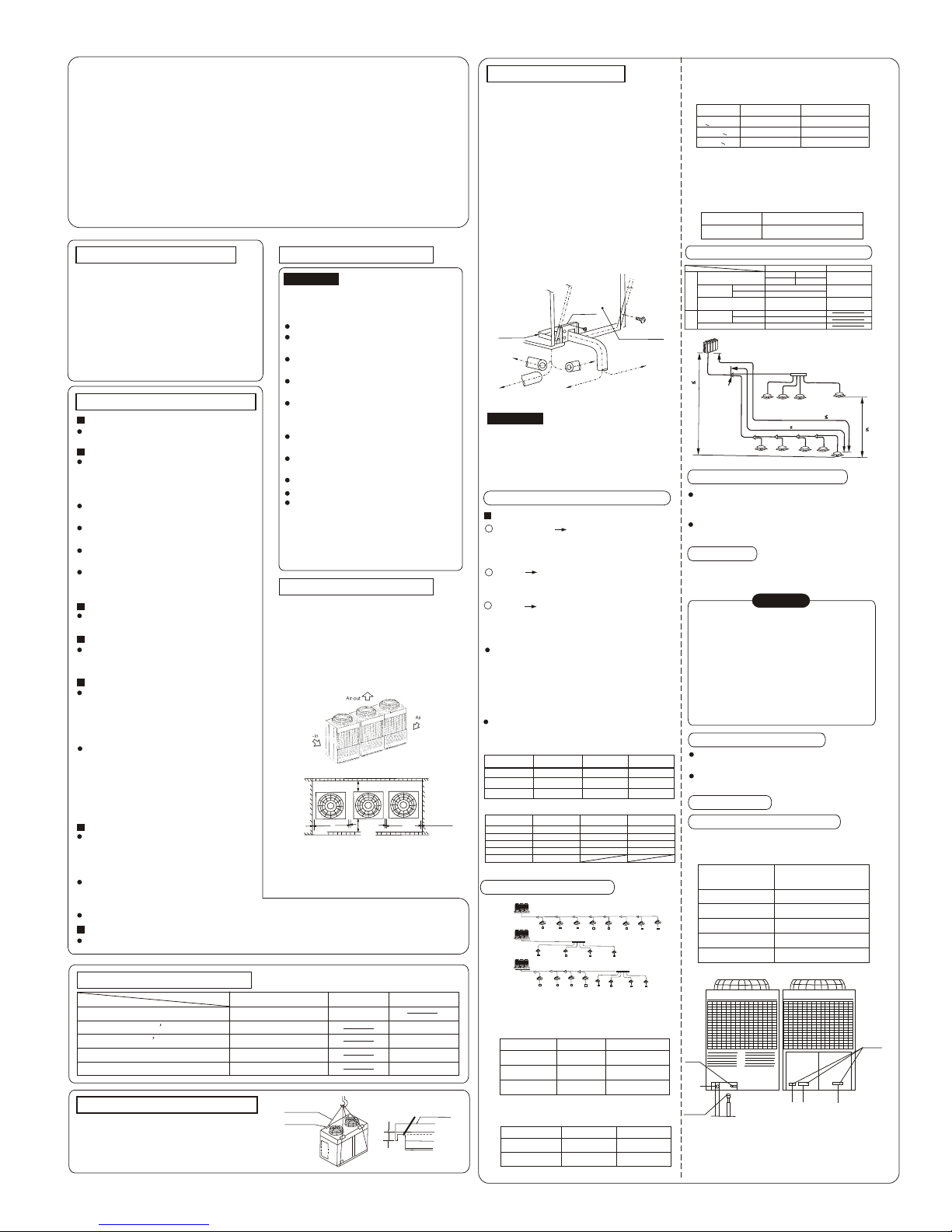
1. Enough repairing space showing below
should be left during installation. When
install the outdoor unit, set the power
equipment at the side of the outdoor
unit, please refer to the power equipm ent installation manual.
2. Be sure to left enough room for installat ion and maintenance. (See Fig. Below)
INSTALLATION SPACE
Air-out
Air-in
Air-in
Install & Repair Surface.
10mm
10mm
1000mm
Or more
Or more
10mm
(Facade)
10mm or more
1000mm or more
Outdoor unit platform
NOTE: 1. Let the obstacle above the outdoor
unit at least 2000mm away.
2. The top of any pile around the outdoor
unit should at least 400mm below the unit top.
REFRIGERANT PIPING
1. Please remove the left-hand board first for
the connection of the refrigerant piping is ins ide the outdoor unit.(M6: 4; M4:1)
2. The pipe can be lead out through the down left corner of the front of the outdoor unit or
the soleplate gap.
3. When through out of the front, lead the pipe
out by wiring from the panel,and install the
refrigerant distributor at left or at right.
4. After through out of the soleplate, install
the refrigerant distributor at left,right or
rear direction.
5. When through out from the front, seal the so leplate gap with the rubber board to keep the
dust and rubbish out of the unit.
(M6)
(M4)
Soleplate for
piping and
wiring
Soleplate
Rear-Leading
piping
Left-Leading
piping
Left-Leading
piping
Right-Leading
piping
Panel for serving
Right-Leadin
g
piping
Select Sizes of Refrigerant Pipes and Materials
Select Sizes of Refrigerant Pipes
Outdoor Unit the Piping at the first
branch (Main piping)
Refer to table 1 for outdoor unit pipe
sizes.
1
1
1.25
1.7
2
2.5
3
3.2
4
5
Outdoor Unit
Capacity Rating
28 type
80type
36 type
90 type
45 type
56 type
112 type
140 type
71 type
Capacity Rating
Capacity
(horsepower)
Capacity
(horsepower)
Capacity of outdoor
unit(horsepower)
Sum Capacity of indoor
unit(horsepower)
Maximum Quantity
of Indoor unit
Size and Connecting Method
f28.6(Welding)
f38.0(Welding)
f45.0(Welding)
f12.7(Flaring nut)
f19.0(Flaring nut)
f22.0(Welding)
1. Table 1
Piping sizes and connecting method of the
outdoor unit.
MDV-D280W/SN2
MDV-D280W/S
MDV-D560W/SN2
MDV-D560W/S
MDV-D840W/SN2
MDV-D840W/S
Models
Gas Side
Liquid Side
2. Table 2
Piping sizes at the branch pipe
A: the total HP of indoor units
Header branch pipe
Branch joint
Note: The indoor unit must be connected with
MDV-HY1041 directly ,the further branch
connection is not allowed.
Length and Drop Height Permitted of the Refrigerant piping
100m
125m
40m
50m
30m
15m
250m
300m
L1+L2+L3+L4+L5+L6+L7
L1+L3+L4+L5+L6+j
L3+L4+L5+L6+j
+A+b+c+d+e+f+g+h+i+j
Permitted value
Total Pipe Length (Actual)
Maximum Piping (L)
Indoor Unit to Indoor Unit Drop Height
Indoor Unit-Outdoor
Unit Drop Height
Piping (farthest from the first line
pipe branch) Equivalent Length
Actual Length
Equivalent Length
Outdoor Unit Up
Outdoor Unit Down
Pipe Length
Drop
Height
Piping
Make sure there is no any dirt or water
before connecting the piping to the outdoor
Units.
Wash the piping with high pressure nitrogen,
never use refrigerant of the outdoor unit.
Remove Dirt or Water in the Piping
Airtight Test
Charge pressured nitrogen after connecting
indoor unit/outdoor unit piping to do airtight
test.
2
1. Pressured nitrogen [2.94MPa (30kg/cm )]
should be used in the airtight test.
2. Tighten high pressure/low pressure
valves before applying pressured nitrogen.
3. Apply pressure from air vent mouth on the
high pressure/low pressure valves.
4. The high pressure/low pressure valves
are closed when applying pressured nitrogen.
5. The airtight test should never use any
oxygen, flammable gas or poisonous gas.
Air Purge with Vacuum Pump
Open All Valves
Refrigerant Amount to be Added
Using vacuum pump to do the vacuum,never
using refrigerant to expel the air .
Vacuuming should be done from both liquid
side and gas side simultaneously.
Calculate the added refrigerant according to the
diameter and the length of the liquid side
pipe of the outdoor unit/indoor unit connection.
TEST RUNNING
The test running can not begin until the outdoor unit has been connected to the power for 12hr.
1. Sling the outdoor unit and carry it in with
4 steel wire (f6mm or more)
2. Use soft board to protect the unit surface
from scratch and distortion at where contact
the steel wire.
CARRY IN THE OUTDOOR UNIT
20
Steel wire
Mopboard
Soleplate
Give owner
Give owner
For maintenance
For the toggle switch
MDV-D280W/S(N2)
MDV-D560W/S(N2)
MDV-D840W/S(N2)
1
1
2
1
1
ACCESSORIES(outdoor unit)
Model
Name
Outline
Usage
Outdoor unit installation manual
Screws bag
Screw driver
This manual
Outdoor unit owner s manual
Indoor unit owner s manual
Model: MDV-D280W/SN2
MDV-D560W/SN2
MDV-D840W/SN2
MDV-D280W/S(N2)
MDV-D560W/S(N2)
MDV-D840W/S(N2)
10
20
30
16
20
30
5~13.5
10~27
15~40.5
2. Table 1
Select branch pipe
NAME
PIPE LOCATION
NUMBER IN THE TABLE
Directly connect to the
indoor unit
No directly connect to
the indoor unit
3
1, 2
A(HP)
Header branch pipe
(Gas side/ liquid side)
Branch joint
A< 10
10< A < 20
20<A < 30
f 28.6/ f 12.7
f 38.0 / f 19.0
f 45.0 / f 22.0
4. Table 4
Piping sizes and connecting method of the
Indoor Unit.
f19.0(Flaring nut) f9.5(Flaring nut)
Gas Side
Liquid Side
10 HP
20 HP & 30 HP
f 9.5
f 12.7
f 15.9
f 19.0
f 22.0
0.065kg
0.115kg
0.190kg
0.290kg
0.380kg
Low
Pressured
Valve
High
Pressured
Valve
Joint
Indoor Unit
& Branch pipe
Terminal
Connecting
Block
Connecting
signal wire
Connecting
power wire
Connecting
power wire
MDV03I-017bW
MDV-BY101 MDV-HY1041
MDV-BY102
MDV-BY103
11
223322 22 22 22 22
33 33 33 33 33 33 33
11
33
33
33
33
11
22
22
22 22
33 33 33 33
33
33 33
33
Outdoor Unit
Outdoor Unit
Outdoor Unit
CAUTION
To prevent the refrigerant piping from oxidizing inside when welding, it is necessary to
charge nitrogen, or oxide will choke the
circulation system.
CAUTION:
Page 2
Name Quantity
2-core
Size
Indoor/Outdoor Unit Signal Wire
22
1.0mm 500m RVVP-1.0mm X2
Model of indoor unit
Room Name
For example: Indoor unit (A)
of the first system on second
floor is record as: 2F 1A.
Outdoor Unit
Ground
(Open)
(Series Control)
(Open)
Indoor/Outdoor
Unit Signal
Wire
Close end of the connection shield wire
ITEM
MODEL
Non Electric
Heating
Electric
Heating
Indoor Unit
Power
source
2
Minimum wire diameter(mm )
Dimension(m)
(continuous length)
2.0
(30m)
3.5
(50m)
f1.6mm
30
15
Single
Phase
220V~
50Hz
3-Phase
380V~
50Hz
Leakage
protector
Grounding Capacity
Fuse
Manual switch(A)
20A 30mA
0.1sec or
less
£¬
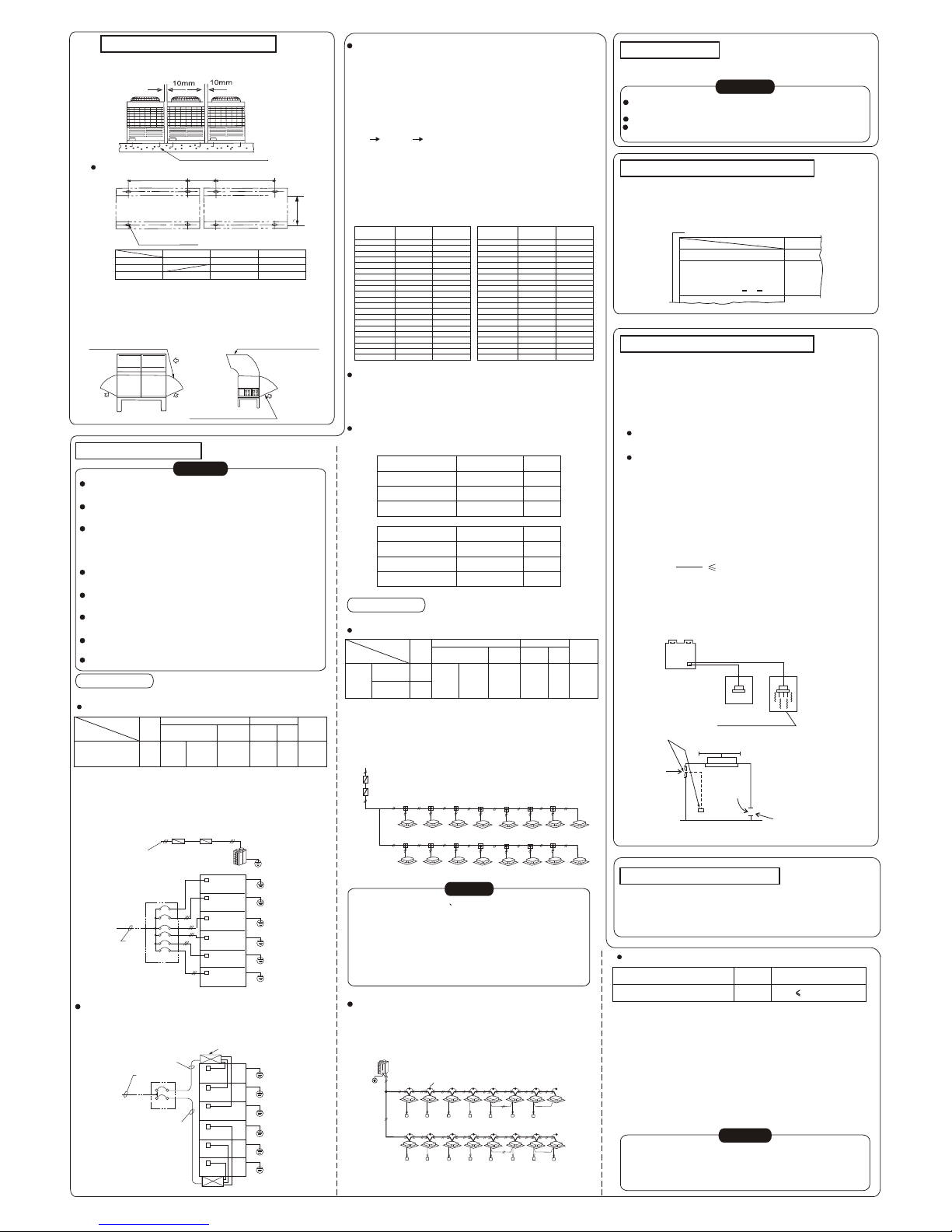
Distance between foot screws is shown as follow.
(15x20 Long hole)
A
B
C
Air inlet snow proof shed Air outlet snow proof shed
Air inlet snow proof shed
2. In snowy places, equipment should be installed to prevent
snow.(As the figure below)(defective snow proof equipment
is easy to cause malfunction).To reduce the affection by
collective snow, please lift the bracket high, and install shelf
at the air inlet and air outlet.
ELECTRICAL WIRING
CAUTION:
Please select power source for indoor unit and outdoor unit
respectively.
The power supply has specified branch circuit with leakage
protector and manual switch.
The power supply leakage protector and manual switch
on all the indoor unit connecting to the same outdoor unit
should be universal.(Please set all the indoor unit power
of one system into the same branch circuit.)
Please put the connective piping system between indoor
unit and outdoor unit with the refrigerant system together.
Use 2-core screened wire as indoor and outdoor control
wire.
Please design a separate circuit for compressor heater
inside the unit for it is frequently heated in using season.
The installation should comply with relevant national electric
standard.
Power wiring should be engaged by specialized electrician.
< Outdoor Unit Wiring>
Separate Power Supply (without power facility)(Table 1)
ITEM
MODEL
Power
source
2
Minimum wire diameter(mm )
Dimension(m)
(continuous length)
MDV-D280W/SN2
MDV-D280W/S
25(46)
16(29)
35(78)
16
60 50
380~415V
3N~
50Hz
Leakage
protector
Grounding Capacity
Fuse
Manual switch(A)
100mA
0.1sec or
less
POWER WIRING
NOTE: The wire diameter and continuous length is under the
condition that the voltage vibration is within 2%. If the
continuous length is exceed the above value, choose
the wire diameter according to relevant regulation.
With Power Facility
Outdoor power
supply
380~415V 3N~
50Hz
Leakage protector
Leakage protector
Manual switch
Junction part
Outdoor
unit
Outdoor
unit
Outdoor
unit
Outdoor
unit
Outdoor
unit
Outdoor
unit
Manual
switch
Grounding
Grounding
Grounding
Grounding
Grounding
Grounding
( a )
(b)
(b)
Junction part
Power facility
(with leakage protector)
Outdoor
unit
Outdoor
unit
Manual switch( A )
Grounding
Grounding
Grounding
Grounding
Grounding
Grounding
The power wiring is the mainline (a) to the junction box and
the wiring (b) from the junction box to power facility. Please
choose as following:
(1) Diameter of the mainline (a)
Index Table 2: the sum of the outdoor unit horsepower.
For example: (5 horsepower X 1 unit + 8 horsepower X1
unit + 10 horsepower X 1 unit) = 23 horsepower (The total horsepower)
2
(table.2) wire diameter=60mm (50m below)
(2) Wire diameter(b) between junction box and power
Facility
When the assembled outdoor units is 5 or less, the same
with the mainline. When the group is up to 6 or more, the
control box of the power facility will be divided
into two, and index Table 2 with the sum of the outdoor unit
horsepower.
Choose the wire diameter
2
Choose wire diameter (not less than)(Unit: mm )
10
11
12
13
14
15
16
17
18
19
20
21
22
23
24
25
26
27
28
29
30
31
32
33
34
35
36
37
38
39
40
41
42
43
44
45
46
47
48
49
50
9
9
13
13
13
13
23
23
23
23
23
23
36
36
36
36
36
36
36
60
60
60
60
60
60
60
60
60
60
60
90
90
90
90
90
90
90
90
90
90
90
60
60
60
60
60
60
90
90
90
90
90
90
90
90
90
90
90
90
90
90
23
23
23
23
36
36
36
36
36
36
36
36
60
60
60
60
60
60
60
60
60
Sum of
Horsepower
Sum of
Horsepower
20m or less 20m or less
Wire length is Wire length isWire length is Wire length is
50m or less 50m or less
Choose the manual switch and fuse capacity for junction box.
(1) Decided by the connected outdoor unit (See Table 1),
when power facility is not concerned.
(2) As concerning to the power facility, according to the outdoor
unit horsepower sum to choose .(See Table 3)
Sum of Horsepower, Manual Switch and Fuse capacity List
(Table 3)
10~14
100 75
15~18
100 100
19~28
150 150
Sum of Horsepower
Manual Switch (A) Fuse (A)
29~36
200 200
37~47
300 250
48~50
300 300
Sum of Horsepower
Manual Switch (A) Fuse (A)
POWER WIRING
< Indoor Unit Wiring>
Power Supply (Table 1)
NOTE: The wire diameter and continuous length is under the
condition that the voltage vibration is within 2%. If the
continuous length is exceed the showing value, choose
the wire diameter follow relevant regulation.
Single Phase 220-240V~ 50Hz
Current leakage Protector
Manual Switch
Wire Distribution Box
Indoor Unit
Indoor Power Supply
1
9
2103
11
4
12
5
13
6
14
7
1515
8
1616
CAUTION
1. Refrigerant piping system indoor unit-indoor unit connection
signal wires and indoor unit-outdoor unit connection signal wire
are in the same system.
2. When power cord is parallel with signal wire, please put
them into separate wire distribution pipes, and leave a proper
distance.
(Reference distance: It is 300mm when current capacity of
power cord is less than 10A, or 500mm when 50A).
Please use shield wire as indoor unit/outdoor unit signal
wire.
Indoor/Outdoor unit signal wire wiring
TEST RUNNING
Operate according to "gist for test running" on the electric control
box cover
CAUTION:
Test running can not start until the outdoor unit has been
connected to the power for 12hr.
Test running can not start until all the valves are affirmed open.
Never make the forced running .(Or the protector sits back ,
danger will occur.)
FILL THE NAME OF CONNECTION SYSTEM
To clearly identify the connection systems between two or
more indoor unit and outdoor unit, selects names for every
system and records them on the nameplate on the outdoor
electric control box cover.
PRECAUTION ON REFRIGERANT LEAK
A[kg]
3
B[m ]
This air conditioner (A/C) adopts R407C or R22 as refrigerant,
which is innocuous and nonflammable. The locating room of
the A/C should big enough that any refrigerant leakage is unable
to reach critical thickness. So certain essential action can be
taken on time.
Critical thickness------the Max. thickness of Freon without
any harm to person.
3
Refrigerant critical thickness: 0.3[kg/m ]
Confirm the critical thickness through follow steps, and take
necessary actions.
1. Calculate the sum of the charge volume (A[kg]) Total
Refrigerant volume of 10HP= factory refrigerant volume +
superaddition
3
2. Calculate the indoor cubage (B[m ]) (as the minimum
cubage)
3. Calculate the refrigerant thickness
Countermeasure against over high thickness
1. Install mechanical ventilator to reduce the refrigerant thic kness under critical level. (ventilate regularly)
2. Install leak alarm facility related to mechanical ventilator if
you can not regularly ventilate.)
3
critical thickness: 0.3[kg/m ]
b. Leak alarm related to mechanical ventilator
A. Ventilation
peristome
(Leak hunting siren should be installed
in places easily keep refrigerant)
Indoor unit
Outdoor unit
Indoor
unit
Room full of leak refrigerant
(All refrigerant has run up)
The owner's manual of indoor unit and owner's manual of
outdoor unit must be turned over to the customer.
Explain the contents in the owner's manual to the customers
in details.
TURN OVER TO CUSTOMER
Indoor/Outdoor unit signal wire is low voltage circuit.
Do not let it touch the high voltage power wire and put
it to gather with power cord in the same wire distribution pipe.
CAUTION
Wire Size and Quantity
1. Signal wire is 2-core, polarized wire. Use 2-core shield wire
to prevent interference from outdoor. The grounding method
now is grounding the closed end of the shield wire and
opening (insulating) at the end. One point on outdoor side
is to be grounded.
2. The control between outdoor unit and indoor unit is
BUS type. Addresses is set on field during the installation.
Leakage protector
Table 2
OUTDOOR UNIT INSTALLATION
1. A 10mm distance should be left
between outdoor units.
M12 Foot screw 4Pieces per unit
<650mm
Type
Size
A
B
C
10HP 20HP
30HP
1030
1030
2025
55
2025
3020
55
3020
The power supply of 20HP or 30HP is separated. Each item supply please refer to above MDV-D280W/SN2 .
 Loading...