

Page 1
f
9.5
f
12.7
f
15.9
0.065kg
0.115kg
0.190kg
H 8m
L
1
L
2
L
3
L
4
L
5
L
6
F
G
H
I
J
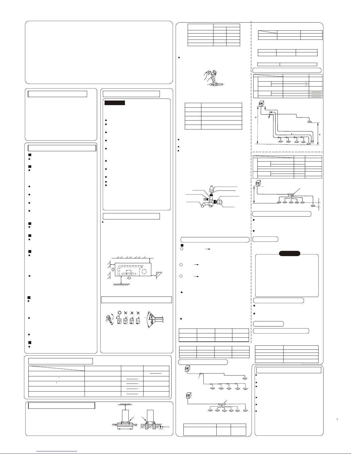
Outdoor Unit (one or more outdoor units)
The first Line Branch Pipe
Indoor Unit
Indoor Unit
Indoor Unit to Indoor Unit
Drop Height
Maximum Piping Equivalent Length L
(From the first Line branch pipe) Maximum piping
Equivalent Length L 20m
Drop Height between Indoor
unit and outdoor Unit H 50m
Digital Scroll Central Air Conditioner (Family used)
(Outdoor Unit)
Installation Manual
PRECAUTION
Precautions before reading the installation
manual.
1. This installation manual is for the outdoor
unit.
2. Refer to the indoor unit installation manual
for indoor parts installation.
3.Please read the power source unit installation
manual to install the power source unit .
4. Please refer to the refrigerant distributor
installation manual to install the refrigerant
distributor.
IMPORTANT CHECKING POINTS DURING INSTALLATION
INSTALLATION
Confirm the model and name of your air
conditioner to avoid installation mistakes.
REFRIGERANT PIPING
Separately purchased refrigerant distributor (branch connection, header branch
pipe) should be used in the process or
refrigerant piping.
Refrigerant piping should meet the specified diameters.
Charge nitrogen under certain pressure in
the refrigerant piping before welding.
Refrigerant piping should undergo the heat
insulation process.
After the installing refrigerant piping, do not
electrify the indoor unit before the airtight
test and vacuum.
AIRTIGHT TEST
Refrigerant piping must be tested for gas
2
proof [2.94Mpa(30kg/cm ) nitrogen]
VACUUM
Vacuum pump must be used, and vacuuming should be done from the gas side and
liquid side simultaneously.
ADD REFRIGERANT
When the actual pipe length is longer than
the base length,the every outdoor unit added
refrigerant volume is decided on the
calculating according to the actual length
of pipes.
Fill the form on the outdoor unit electric
control box with the added volume, length
of pipes (actual length) and the relative
height drop between outdoor unit and indoor
unit.
WIRING
Choose power capacity and wire diameter
according to the design manual. The power
cord of the air conditioner should be wider
than the power cord of ordinary motor.
Never unwind or cross the power cord
(380V~) with signal wire (low voltage)
between indoor and outdoor unit, or malfunction
is unavoidable.
Connect the indoor unit to the power after
airtight test and vacuuming.
INSTALLATION LOCATION
CAUTION:CAUTION:
There is combustible gas leakage existing.
There is much oil (including engine oil)
ingredient.
1. Please keep away from the following
place, or malfunction of the machine
may be caused:
There is salty air surrounding(near the
coast)
There is caustic gas (the sulfide, for example) existing in the air (near a hotspring).
A place the heat air expelled out from the
outdoor unit can reach your neighbor's
window.
A place that the noise interferes your
neighbors every day life.
A place that is too weak to bear the
weight of the unit.
Uneven place.
Insufficient ventilation place.
Near a private power station or high
frequency equipment.
2. The insulation of the metal parts of the
building and the air conditioner should
comply with the regulation of National
Electric Standard.
INSTALLATION SPACE
CARRY IN THE OUTDOOR UNIT
Give owner
Give owner
For maintenance
For the toggle switch
1
1
1
1
1
ACCESSORIES(outdoor unit)
Model
Name
Outline
Usage
Outdoor unit installation manual
Indoor unit owner s manual
Screws bag
Screw driver
This manual
Size and Connecting Method
Outdoor Unit
The first line branch pipe
1
1
2
2
2
2
2
3
3
3
3
3
3 3
3
3
3
f19
(Flaring nut )
f9.53
(Flaring nut)
1. Table 1
Piping sizes and connecting method of the
outdoor unit.
Models
Gas Side
Liquid Side
3. Table 3
Piping sizes and connecting method of the
Indoor Unit.
4. Table 4
Select branch pipe
2. Table 2
Piping sizes at the branch pipe
f19(Welding)
f9.53(Welding)
Gas Side
Liquid Side
f19.0(Flaring nut)
f9.53(Flaring nut)
Gas Side
Liquid Side
Header branch pipe
FQG-01
Length and Drop Height Permitted of the Refrigerant piping
20m
20m
20m
8m
100m
L1+L2+L3+L4+L5+L6
L1+L3+L4+L5+L6+e
L3+L4+L5+L6+e
+A+b+c+d+e
Permitted value
Total Pipe Length (Actual)
Maximum Piping (L)
Indoor Unit to Indoor Unit Drop Height
Indoor Unit-Outdoor
Unit Drop Height
Piping (farthest from the first line
pipe branch) Equivalent Length
Actual Length
Equivalent Length
Outdoor Unit Up
Outdoor Unit Down
Pipe Length
Drop
Height
Piping
Make sure there is no any dirt or water
before connecting the piping to the outdoor
Units.
Wash the piping with high pressure nitrogen,
never use refrigerant of the outdoor unit.
Remove Dirt or Water in the Piping
Airtight Test
Charge pressured nitrogen after connecting
indoor unit/outdoor unit piping to do airtight
test.
CAUTION
2
1. Pressured nitrogen [2.94MPa (30kg/cm )]
should be used in the airtight test.
2. Tighten high pressure/low pressure
valves before applying pressured nitrogen.
3. Apply pressure from air vent mouth on the
high pressure/low pressure valves.
4. The high pressure/low pressure valves
are closed when applying pressured nitrogen.
5. The airtight test should never use any
oxygen, flammable gas or poisonous gas.
Air Purge with Vacuum Pump
Open All Valves
Refrigerant Amount to be Added
Using vacuum pump to do the vacuum,never
using refrigerant to expel the air .
Vacuuming should be done from both liquid
side and gas side simultaneously.
Calculate the added refrigerant according to the
diameter and the length of the liquid side
pipe of the outdoor unit/indoor unit connection.
OUTDOOR UNIT INSTALLATION
TEST RUNNING
The test running can not begin until the outdoor
unit has been connected to the power for 12hr.
e c
Outdoor unit owner s manual
1
1.25
1.7
2
2.5
Outdoor Unit
Capacity Rating
28 type
45type
36 type
56 type
Capacity Rating
Capacity
(horsepower)
Capacity
(horsepower)
Capacity of outdoor
unit(horsepower)
Sum Capacity of indoor
unit(horsepower)
Maximum Quantity
of Indoor unit
71 type
22 type
0.8
Model: MDV-D100W/S MDV-D140W/S
MDV-D100W/SN2 MDV-D140W/SN2
If possible, please remove the obstacles nearby
to prevent the performance from being impeded
by too little of air circulation.
The minimum distance between the outdoor unit
and obstacles described in the installation chart
does not mean that the same is applicable to the
situation of an airtight room. Leave open two of
the three directions (A,B,C)
>30cm
>60cm
>30cm
>2
0
0
cm
(Wall or obstacle)
Maintain channel
Air outlet
Air inlet
Air inlet
A
C
B
REFRIGERANT PIPE CONNECTING
FLARING
>6
0
cm
Fix with bolt
Necessary width
Deep foundation
Since the gravity center of this unit is not at its physical center,
so please be careful when lifting it with a sling.
Never hold the air-in of the outdoor unit to prevent it from deforming.
Do not touch the fan with hands or other objects.
0
Do not lean it more than 45 , and do not lay it sidelong.
Please fasten the feet of this unit with bolts firmly to prevent it from
collapsing in case of earthquake or strong wind.
90
Lean crude burr
Chart
22
A
90+4
_
45+2
_
Chart 23
1. Cut a pipe with a pipe cutter.
2. Insert a flare nut into a pipe and flare
the pipe.(Table 1)
A(mm)
Max
Min
6.35
8.3
9.53
12.4
12.7
15.8
16
19.0
19
23.3
Outside-diameter
(mm)
8.3
12.0
15.4
18.6
22.9
Table 1
FASTEN THE NUT
Put the connecting tubing at the proper position,
wrench the nuts with hands, then fasten it with a
wrench.( Refer to Chart24)
Chart 24
Too large torque will harm the bellmouthing and
too small will cause leakage. Please determine
the torque according to Table 2.
f6.35
.
1000~1200 N cm
f9.53
.
1500~1800Ncm
f12.7
.
2000~2300Ncm
f166
.
2800~3200Ncm
f199
.
3500~4000Ncm
Tubing Size
Torque
Table 2
CAUTION
Operate the stop values
Open the value stem until it reaches the limitator.
Do not open it any further.
Fasten the stop values with a wrench or such tools.
The wrench torque is listed in the Table 2
mentioned above.
CAUTIONS
All the stop values should be opened before test
operation. Each air conditioner has two stop values
of different sizes on the side of the outdoor unit
which operate as Lo-stop value and Hi-stop value,
respectively. The ON/OFF operation is described
in the left chart. (Refer to Chart 28)
Chart 28
Trap body
Repair mouth
System joint
Quadrangle-cover
Quadrangle-lever
Linking pipe joint
Joint nut
1) ON operation: Take off quadrangle cover, clip
the quadrangle head with a wrench and turn
it anticlockwise to the end. Then fasten the
quadrangle cover.
2) OFF operation: The operation is the same as
the ON operation, but you should turn it
clockwise this time.
Branch Piping between indoor units
(Indoor piping)
Refer to table 3 for indoor unit connection
pipes.
Branch Connection Selection
Select according to the indoor units general
design capacity which it connects to.But if
the indoor units design capacity is more than
the outdoor unit design capacity, then select
branch connection according to the outdoor
unit.
Header Branch Selection.
The selection should according to the
number of branches it connects to.
3
Branch Piping between branches
Select pipe diameters according to the
table 2.
2
Select Sizes of Refrigerant Pipes and Materials
Select Sizes of Refrigerant Pipes
Outdoor Unit the Piping at the first
branch (Main piping)
Refer to table 1 for outdoor unit pipe
sizes.
1
4
5
5
6
2~5
2~7
3
3
Method 1: Weld the branches
Method 2:Screw the branches
Outdoor Unit
f19(Flaring nut)
f9.53(Flaring nut)
Method 1
Method 2
TYPE
22~36
60m(140W)or 45m (120W,100W )
70m(140W)or 45m (120W,100W )
Liquid Side Piping
Diameter
Refrigerant to be Added
per meter piping
L
1
A
B
C
D
Outdoor Unit (one or more outdoor units)
Indoor Unit
50m
55m
10m
20m
20m
8m
100m
L1+A+B+C+D+E+F
L1+ F
Permitted value
Total Pipe Length (Actual)
Maximum Piping (L)
Indoor Unit to Indoor Unit Drop Height
Indoor Unit-Outdoor
Unit Drop Height
Piping (farthest from the BS Equipment) Equivalent Length
Actual Length
Equivalent Length
Outdoor Unit Up
Outdoor Unit Down
Pipe Length
Drop
Height
Piping
E
F
Piping (farthest from the BS Equipment) Equivalent Length
40m
A or B,C,D,E,F
L1
L2
L3
Method 1
Method 2
L2
L3
2
Refrigerant Divider
(BS Equipment)
Refrigerant Divider
(BS Equipment)
Keep this unit away from direct radiation of the
sun or other heaters.
If unavoidable, please cover it with a shelter.
In places near coast or with a high attitude where
the wind is violent, please install the outdoor unit
against the wall to ensure normal performance.
Use a baffle when necessary.
In the case of extremely strong wind, please
prevent the air from flowing backwards into the
outdoor unit. ( Refer to chart 16)
Locate the outdoor unit as close to the indoor
unit as possible.
The minimum distance between the outdoor unit
and obstacles described in the installation chart
does not mean that the same is applicable to the
situation of an airtight. Leave open two of three
directions A,B,C..
MDV-03I-010aW
MDV-D100W/S MDV-D140W/S
MDV-D100W/SN2 MDV-D140W/SN2
MDV-D100W/S
MDV-D100W/SN2
MDV-D140W/S
MDV-D140W/SN2
MDV-D100W/S
MDV-D140W/S
MDV-D100W/SN2
MDV-D140W/SN2
f 19
0.280kg
Page 2
Non Electric
Heating
ELECTRICAL WIRING
CAUTION:
Please select power source for indoor unit and outdoor unit
respectively.
The power supply has specified branch circuit with leakage
protector and manual switch.
The power supply leakage protector and manual switch
on all the indoor unit connecting to the same outdoor unit
should be universal.(Please set all the indoor unit power
of one system into the same branch circuit.)
Please put the connective piping system between indoor
unit and outdoor unit with the refrigerant system together.
Use 2-core screened wire as indoor and outdoor control
wire.
Please design a separate circuit for compressor heater
inside the unit for it is frequently heated in using season.
The installation should comply with relevant national electric
standard.
Power wiring should be engaged by specialized electrician.
< Outdoor Unit Wiring>
Separate Power Supply (without power facility)(Table 1)
ITEM
MODEL
Power
source
25
16
380V
3N~
50Hz
Leakage
protector
Capacity
Fuse
Manual switch(A)
100mA
0.1sec or
less
POWER WIRING
NOTE: The wire diameter and continuous length is under the
condition that the voltage vibration is within 2%. If the
continuous length is exceed the above value, choose
the wire diameter according to relevant regulation.
Model of indoor unit
Room Name
For example: Indoor unit (A)
of the first system on second
floor is record as: 2F 1A.
£¬
TEST RUNNING
Operate according to "gist for test running" on the electric control
box cover
CAUTION:
Test running can not start until the outdoor unit has been
connected to the power for 12hr.
Test running can not start until all the valves are affirmed open.
Never make the forced running .(Or the protector sits back ,
danger will occur.)
FILL THE NAME OF CONNECTION SYSTEM
To clearly identify the connection systems between two or
more indoor unit and outdoor unit, selects names for every
system and records them on the nameplate on the outdoor
electric control box cover.
PRECAUTION ON REFRIGERANT LEAK
A[kg]
3
B[m ]
This air conditioner (A/C) adopts R407C or R22 as refrigerant,
which is innocuous and nonflammable. The locating room of
the A/C should big enough that any refrigerant leakage is unable
to reach critical thickness. So certain essential action can be
taken on time.
Critical thickness------the Max. thickness of Freon without
any harm to person.
3
Refrigerant critical thickness: 0.3[kg/m ]
Confirm the critical thickness through follow steps, and take
necessary actions.
1. Calculate the sum of the charge volume (A[kg]) Total
Refrigerant volume of 10HP= factory refrigerant volume +
superaddition
3
2. Calculate the indoor cubage (B[m ]) (as the minimum
cubage)
3. Calculate the refrigerant thickness
Countermeasure against over high thickness
1. Install mechanical ventilator to reduce the refrigerant thic kness under critical level. (ventilate regularly)
2. Install leak alarm facility related to mechanical ventilator if
you can not regularly ventilate.)
3
critical thickness: 0.3[kg/m ]
b. Leak alarm related to mechanical ventilator
A. Ventilation
peristome
(Leak hunting siren should be installed
in places easily keep refrigerant)
Indoor unit
Outdoor unit
Indoor
unit
Room full of leak refrigerant
(All refrigerant has run up)
The owner's manual of indoor unit and owner's manual of
outdoor unit must be turned over to the customer.
Explain the contents in the owner's manual to the customers
in details.
TURN OVER TO CUSTOMER
X
O
Chart 16
Strong wind
Selection of the Power Cable
(mm ) (Please use wire tube
to wrap the cables)
2
MDV-D100W/S
MDV-D140W/S
MDV-D100W/SN2
MDV-D140W/SN2
RVV-450/750
5*2.5mm
2
< Indoor Unit Wiring>
Separate Power Supply (without power facility)(Table 2)
ITEM
MODEL
Power
source
10 5
Leakage
protector
Capacity
Fuse
Manual switch(A)
Selection of the Power Cable
(mm ) (Please use wire tube
to wrap the cables)
2
RVV-300/500
3*1.5mm
2
220V~
50HZ
220V~
50HZ
RVV-300/500
3*2.5mm
2
25
16
20A 30mA
0.1sec or
less
With Electric
Heating
Indoor Unit
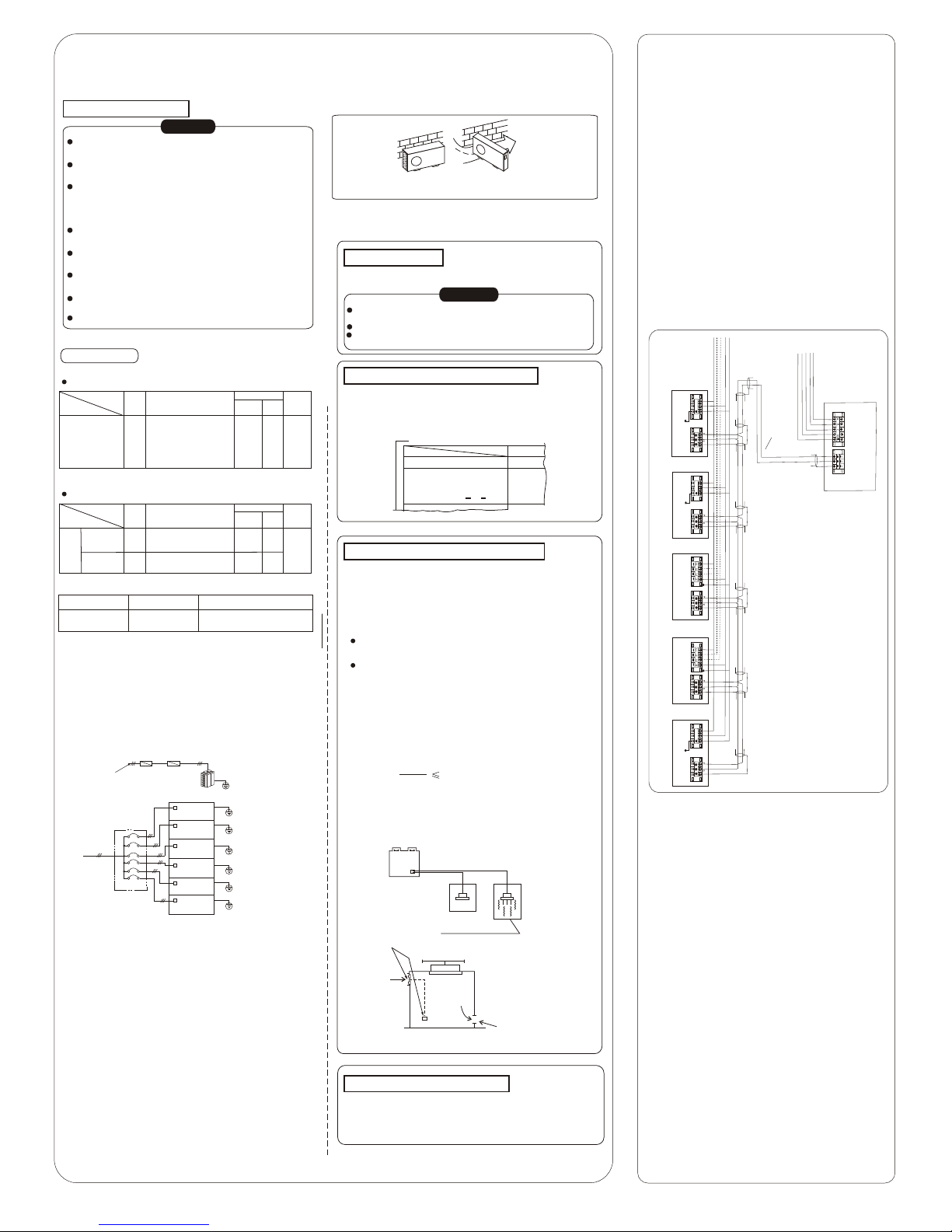
<Signal Wiring for the Controller> (Table 1)
NAME
Insulation Shield Cable
TYPE
RVVP-300/500
2*0.5mm
NOTE
The shied surface of the cable must be
connected to the signal endding(E) of
the outdoor and indoor unit
Outdoor power
supply
380V 3N~
50Hz
Leakage protector
Leakage protector
Manual switch
Junction part
Outdoor
unit
Outdoor
unit
Outdoor
unit
Outdoor
unit
Outdoor
unit
Outdoor
unit
Manual
switch
Grounding
Grounding
Grounding
Grounding
Grounding
Grounding
End of Grounding
FOR Model:
MDV-D100W/S MDV-D100W/SN2
MDV-D140W/S MDV-D140W/SN2
NOTE:
1. Please connect the signal wire correctly, for they have
difference of anode and cathode.
2. Please do not put the signal wire and the power wire
in the same wire tube; the distance between the two
wire tube must be in the range of 300~500mm.
3. Refrigerant piping system, indoor unit -indoor unit signal
wires and indoor unit-outdoor unit signal wire are in the
same system.
4. After finishing connection, do not use Megger to have
insulation check to the signal wire.
L N
£¨E£©
£¨E£©
£¨E £©
L N
£¨E£©
L N
£¨E£©
POWER:
380V 3N~ 50Hz
(E)
MDV-D100W/S MDV-D140W/S
MDV-D100W/SN2 MDV-D100W/SN2
NOTE:
1.When the indoor unit s power source is 1 phase, it has no
links listed by broken line.
2. The quantity of the indoor unit can be chosen by actual needing.
MEANING OF LETTERS:
A: Indoor Unit Power B: Connecting with Outdoor Unit
C: Indoor Electric Controller
Outdoor Unit Controller
Outdoor
Unit Power
Connecting With
Indoor Unit
Xt1
Xt2
Q
P
A
B
A
B
C
A
B
C
A
B
C
A
B
C
C
Indoor-Outdoor Unit
Connecting Signal Wire
(2-core shield wire)
Power:
380V 3N~ 50HZ
220V~ 50HZ
Air Conditioner Link Circuit
XT2
XT2
XT2
XT2
XT2
XT1
XT1
XT1
XT1
XT1
,
 Loading...