

Midea MDV-D252W/CS, MDV-D, MDV-D280W/CS, MDV-D335W/CS, MDV-D450W/CS Installation Manual
...Page 1

MDV[D] Series
Digital Scroll Central Air Conditioner Outdoor Unit
INSTALLATION MANUAL
Model:
MDV-D252W/CS
MDV-D280W/CS
MDV-D335W/CS
MDV-D400W/CS
MDV-D450W/CS
Page 2
PRECAUTIONS
1. This installation manual is for the outdoor unit.
2. Refer to the indoor unit installation manual for indoor parts
installation.
3. Please read the power source unit installation manual to
install the power source unit .
4. Please refer to the refrigerant distributor installation
manual to install the refrigerant distributor.
KEY POINTS IN INSTALLATION
INSTALLATION
Confirm the model and name of your air conditioner
to avoid installation mistakes.
REFRIGERANT PIPING
Separately purchased refrigerant distributor (branch
joint, branch header pipe) should be used in the process
of refrigerant piping.
Refrigerant piping should accord with specified
diameter.
Charge nitrogen under certain pressure in the refrigerant
piping before welding.
Heat insulation should be done to refrigerant piping.
After the installing refrigerant piping, do not electrify the
indoor unit before the airtight test and vacuum.
AIRTIGHT TEST
Refrigerant piping must be tested for gas proof
[2.94MPa(30kg/cm ) nitrogen.]
VACUUM
Vacuum pump must be used, and vacuuming should
be done from the gas side and liquid side
simultaneously.
ADD REFRIGERANT
When the actual pipe is longer than the fiducial length,
the added refrigerant volume of every outdoor unit
depends on the calculating according to the actual length.
Fill the form on the outdoor unit electric control box with
the added volume, length of pipes (actual length) and the
relative height drop between outdoor unit and indoor unit.
WIRING
Choose power capacity and wire diameter according to
the design manual. The power cord of the air conditioner
should be wider than the power cord of ordinary motor.
Do not twist or cross the power cord with wiring (low
voltage) between indoor and outdoor unit, or mishandling
may occur.
Connect the indoor unit to the power after airtight test
and vacuuming.
Set the address of outdoor unit, see Address dial
of outdoor unit
TEST RUNNING
Remove six sponges at the back of unit. Please handle
with care to avoid damage to fin, which will decrease
heat exchanging efficiency.
The test running can not begin until the outdoor unit has
been connected to the power for 12hr.
2
INSTALLATION LOCATION
CAUTION
1. Please keep away from the following place, or
malfunction of the machine may be caused:
There is combustible gas leakage.
There is much oil (including engine oil) ingredient.
There is salty air surrounding(near the coast)
There is caustic gas (the sulfide) existing in the air (near
a hotspring).
A place the heat air expelled out from the outdoor unit
can reach your neighbor's window.
A place that the noise interferes your neighbors every
day life.
A place that is too weak to bear the weight of the unit.
Uneven place.
Insufficient ventilation place.
Near a private power station or high frequency equipment.
A place with strong electromagnetic interference.
2. The insulation of the metal parts of the building and the
air conditioner should comply with the regulation of
National Electric Standard.
ACCESSORIES
Name
Outdoor unit installation manual
Outdoor unit owner s manual
Indoor unit owner s manual
Service manual(guarantee
and bar code inside)
Screw bag
Straight screwdriver
Gauge joint
90 elbow
(Outdoor unit)
Qty.
Outline
This manual
1
1
2
1
1
1
1
2
Function
(Given to users)
(Given to users)
(Given to users)
Spare
Dialling
For airtight test
Pipe connecting
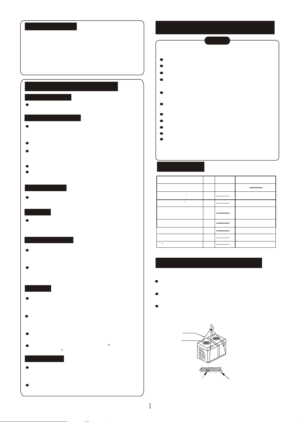
CARRY IN THE OUTDOOR UNIT
1. Carry in with steel wire:
Sling the outdoor unit and carry it in with 4 steel wire
(f6mm or more)
Use soft board to protect the unit surface from scratch
and distortion where contact the steel wire.
Remove the transportation board after carrying in the
outdoor unit.
2. Carry in with a fork lift
Steel wire
Protection board
Hole site for fork lift
Chassis
Page 3
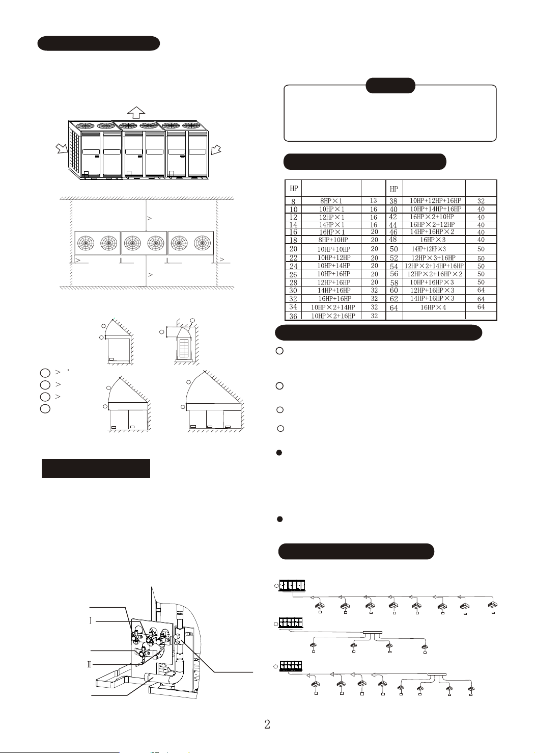
INSTALLATION SPACE
1. Leave enough space for maintenance (see following
picture) and install power unit on the side of outdoor
unit. Refer to power unit installation manual.
2. Keep the modules in one system at the same level.
(Air-out )
(Air-in )
(Air-in )
5. If through the front, please remove the clapboard
at corresponding place first.
CAUTION
To prevent the inside of piping from oxidizing
when welding, it is necessary to charge nitrogen,
or oxide may block the circulation.
OUTDOOR UNIT COMBINATION
Installation and maintenance surface
1000mm
1000mm
20mm~ 500mm
20mm~ 500mm
1000mm
1000mm
Outdoor unit planform
2. When there is obstacle above the outdoor unit:
A
B
Front view
45
A
300mm
B
1000mm
C
D
Airflow deflector
Front view
NOTE: The top of any pile around the outdoor unit should at least 800mm
below the top of unit. If not, please install mechanical air discharge equipment.
A
B
C
Side view
Front view
D
A
B
REFRIGERANT PIPE
1. Refrigerant piping connection is inside the outdoor
unit, please remove the front clapboard.
2. The piping can be led through the down-left of the
outdoor unit or the soleplate gap.
3. When through the front, piping is led by wiring from
the panel, then connect branch pipes towards left
or right.
4. When through the soleplate gap, install the branch
pipe towards left, right or back.
To liquid side pipe
To gas balance pipe
(flaring nut)
To oil balance pipe
To gas balance pipe
(welding)
To gas side pipe
NOTE: No connection
with gas and oil balance
pipes for single module.
Low-pressure
ball valve
Mode
Qty. of
indoor unit
Mode
SELECT SIZES OF REFRIGERANT PIPES
1
Pipe between outdoor unit and the first
branch (Main pipe)
Refer to table 1 for outdoor unit pipe sizes.
Size of main pipe connecting multi-modules
2
See table 2
3
Pipe between branches
See table 3
4
Pipe between branch and indoor unit
See table 4
Select branch joint
Select the joint according to the total designed
capacity of indoor units which it connects to. If this
capacity is more than that of the outdoor unit, then
select the connection according to the outdoor unit.
The selection of branch header depends on
the quantity of branches it connects to.
22
33
33
(See table 3)
22
33
33
33
PIPE SIZE AND CONNECTION
Outdoor unit
11
11
Outdoor unit
22
Outdoor unit
33
11
22
33
33
22
33 33
33
11
22 22
22
33
33 33 33
22 22 22
33 33
33
33
Qty. of
indoor unit
33
33
Page 4
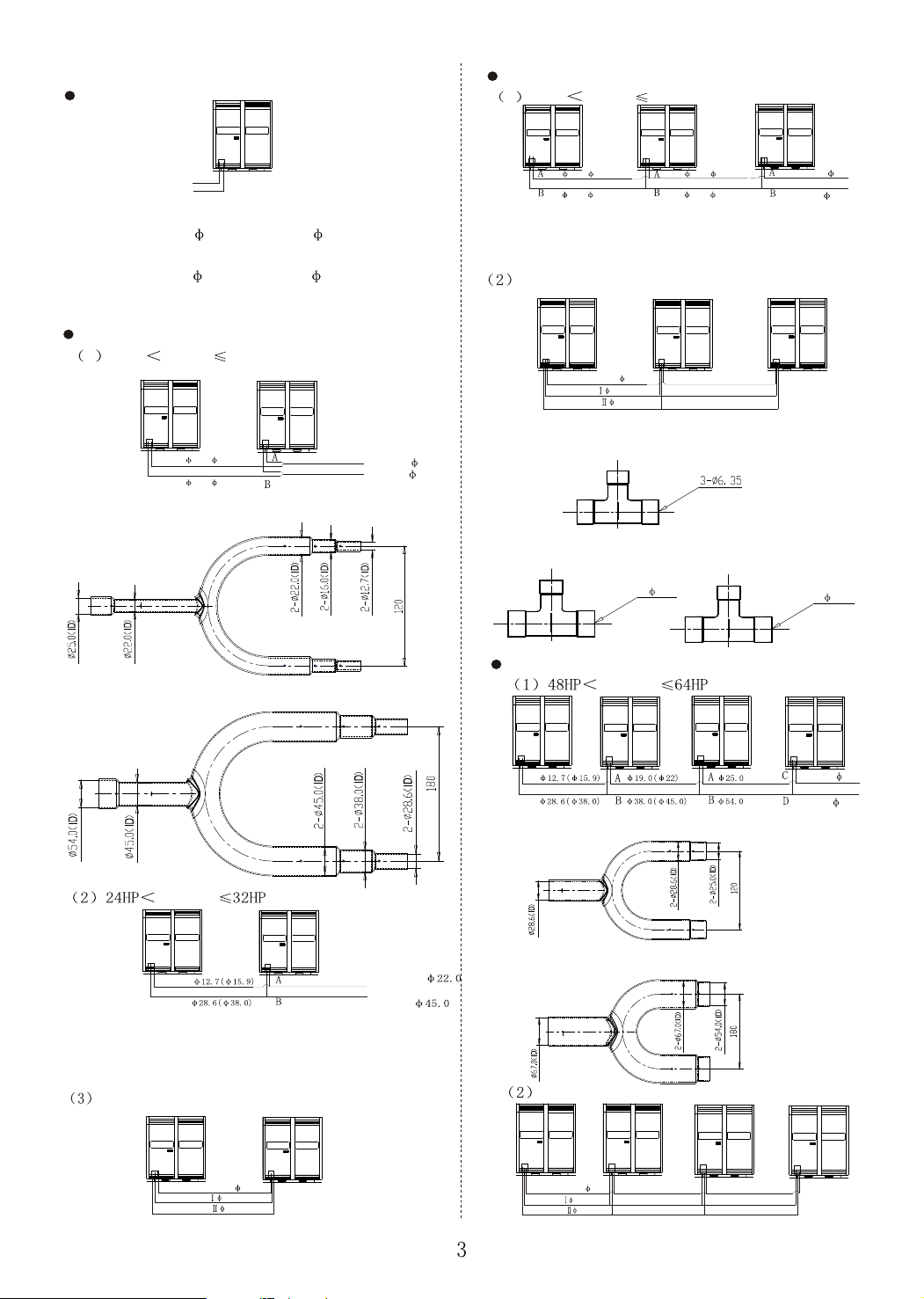
<Module installation chart>
Single module
Three modules
1 32HP capacity 48HP
Liquid pipe
Gas pipe
NOTE: Pipe size of model 8HP, 10HP and 12HP:
liquid side 12.7, gas side 28.6.
Pipe size of model 14HP and 16HP:
liquid side 15.9, gas side 38.0.
Gas and oil balance pipes should be sealed by welding
for single module.
Two modules
1 16HP capacity 24HP
12.7( 15.9)
28.6( 38.0)
Liquid pipe 19.0
Gas pipe 38.0
NOTE: See following chart for size of Y-shaped
pipe A on liquid side:
See following chart for size of Y-shaped
pipe B on gas side:
12.7( 15.9)
28.6( 38.0)
19.0( 22)
38.0( 45.0)
Liquid pipe 25.0
Gas pipe 54.0
NOTE: The size of Y-shaped pipes A and B on liquid
side and gas side respectively are the same
with that specified in item(1) of two modules.
Connection of oil and gas balance pipes
Oil balance pipe 6.35
Gas balance pipe 15.9(flaring nut)
Gas balance pipe 19.0(welding)
X
Y
Z
NOTE: See following chart for size T-shaped pipe X
connecting with oil pipe.
See following chart for size T-shaped pipes Y and Z
connecting with gas pipe.
Y
Four modules
3- 15.9
Z
3- 19.0
capacity
capacity
Liquid pipe
Gas pipe
NOTE: The size of Y-shaped pipes A and B on liquid
side and gas side respectively are the same
with that specified in item(1).
Connection of oil and gas balance pipes
NOTE: Wrap the valves
with wet cloth when welding,
or the valves may be
Oil balance pipe 6.35
Gas balance pipe 15.9(flaring nut)
Gas balance pipe 19.0(welding)
damaged to cause leakage.
NOTE: See following chart for size of Y-shaped
pipe C on liquid side:
See following chart for size of Y-shaped
pipe D on gas side:
Connection of oil and gas balance pipes
Oil balance pipe 6.35
Gas balance pipe 15.9(flaring nut)
Gas balance pipe 19.0(welding)
X
Y
Z
X
Y
Z
Liquid pipe 28.6
Gas pipe 67.0
Page 5

NOTE: The size of T-shaped pipe X connecting with
oil pipe is the same with that specified in three modules.
The sizes of T-shaped pipes Y and Z connecting with
gas pipe are the same with that specified in three modules.
1 Table 1
Pipe size and connection of outdoor unit
Model
MDV-D252W/CS
MDV-D280W/CS
MDV-D335W/CS
MDV-D400W/CS
MDV-D450W/CS
Gas side
28.6(welding)
28.6(welding)
28.6(welding)
38.0(welding)
38.0(welding)
Liquid side
12.7(flaring nut)
12.7(flaring nut)
12.7(flaring nut)
15.9(flaring nut)
15.9(flaring nut)
2 Table 2
Size of main pipe connecting multi-modules (unit: mm)
Capacity of parallel unit A (HP) Pipe size (gas/liquid)
3 Table 3
Type of pipe
Name
Branch pipe
Main pipe
4 Table 4
Size of main pipe
A: Capacity of all the indoor units.
A(horsepower)
A12
12A16
16A24
24A32
32A48
48A64
Main pipe(gas side/liquid side) Branch joint
Pipe location
Directly connect to indoor unit
Not directly connect to indoor unit
F28.6/ F12.7
F38.0/ F15.9
F38.0/ F19.0
F45.0/ F22.0
F54.0/ F25.0
F67.0/ F28.6
MDV-BY101
MDV-BY102(A) (refit)
MDV-BY102(A)
MDV-BY103(A)
MDV-BY104
MDV-BY105
Number in chart
3
12
Note: Select the first branch joint based on the capacity of outdoor
unit, which should be larger than other branch joints.
4.Take 30HP outdoor unit for example:
1 a 2 b 3 c 4 d 5 e 6 f 13
7 8 9 10 11 12
#
#2#3#4#
1
(5P) (5P) (5P) (5P) (3P) (2P)
5
Determine pipe size
1. Branch pipes: No.7, 8, 9, 10,11, 12 and 13 the size is F19.0/F9.53
2. 6# and 7# indoor units connect with pipe 6, total HP is 2+5=7P 10P pipe size is
F28.6/F12.7, model of branch join: MDV-BY101
3. Subordinate indoor units of pipe 5 are :5#, 6# and 7#, total HP is 3+2+5=10P 10P,
pipe size is F28.6/ F12.7, model of branch joint: MDV-BY101
4. Subordinate indoor unis of pipe 4 are 4#, 5#, 6# and 7#, total HP is 5+3+2 +5=15P
16P, pipe size is F38.0/F15.9, model of branch joint:MDV-BY102(A)
5. Subordinate indoor units of pipe 3 are 3#, 4#, 5#, 6# and 7#, total HP is 5+5+3+2+5=
20P 24P, pipe size is F38.0/F19.0, model of branch joint:MDV-BY102(A)
6. Subordinate indoor units of pipe 2 are 2# 7#, totel HP is 5+5+5+3+2+5=25P 32P,
pipe size is F45.0/F22.0, model of branch joint:MDV-BY103(A)
7. Pipe 1 is main pipe, the size is F45.0/F22.0, model of branch joint: MDV-BY103(A)
4. Table 5
Pipe size and connection of indoor unit
Gas side
F19.0 flaring nut 9.53 flaring nut
Length and Drop Height Permitted of the Refrigerant piping
Permitted value
20HP
Total Pipe Length (Actual)
Max Piping (L)
Pipe Length
Piping (farthest from the first line
pipe branch) Equivalent Length (l)
Indoor-Outdoor Unit
Drop Height(H)
Drop
Height
Indoor Unit to Indoor Unit Drop Height(h)
Actual Length
Equivalent Length
Outdoor Unit Up
Outdoor Unit Down
20HP
130m
150m
40m
50m
30m
15m
250m
300m
7#
5P
#
6
Liquid side
Piping
L1+L2+L3+L4+L5+L6
+a+b+c+d+e+f+g+h+i
L1+L3+L4+L5+L6+i
L3+L4+L5+L6+i
Outdoor Unit (one or more outdoor units)
L
Branch header
2
b
Indoor Unit
L
5
f
c
L
6
g
h
a
Max Piping Equivalent Length L 125m
L
4
Indoor Unit
d
h 15m
Indoor Unit to Indoor Unit
Drop Height
i
Drop Height between Indoor
unit and outdoor Unit H 50m
L
1
First branch
L
3
(From the first branch) Max piping Equivalent Length l 40m
e
Remove Dirt or Water in the Piping
Make sure there is no any dirt or water before
connecting the piping to the outdoor units.
Wash the piping with high pressure nitrogen, never
use refrigerant of the outdoor unit.
Airtight Test
1. Connect piping on hi-pressure side with hi-pressure
valve. (For multi-modules parallel connection, please
connect gas and oil balance valves.)
2. Weld the piping on low-pressure side with gauge joint.
3. Charge nitrogen from hi-pressure valve core and gauge
joint.
4. After airtight test, weld low-pressure ball valve and
piping on low--pressure side.
CAUTION
1. Pressured nitrogen [2.94MPa (30kg/cm ) should be used in the
airtight test.
2. Do not connect piping on low-pressure side and low-pressure ball
valve before charging nitrogen.
3. The airtight test should never use any oxygen, flammable gas
or poisonous gas.
4. Wrap low-pressure valve and balance valves with wet cloth while welding.
Gas balance valve
Gas balance valve
Oil balance valve
Hi-pressure valve
Gauge joint
Indoor unit and branch joint
2
Low-pressure ball valve
Vacuum with vacuum pump
Do vacuum with vacuum pump instead of refrigerant.
Vacuuming should be done from liquid and gas side
simultaneously. The pressure should be lower than
30Pa.
Open all valves
Refrigerant Amount to be Added
Calculate the added refrigerant according to the diameter
and the length of the liquid side pipe of the ou tdoor/indoor
unit connection. The refrigerant is R22.
Pipe size on liquid side
f
9.53
f
12.7
f
15.9
f
19.0
f
22.0
f
25.0
f
28.6
Refrigerant to be Added per meter
0.065kg
0.115kg
0.190kg
0.290kg
0.380kg
0.580kg
0.760kg
Page 6

Outdoor unit address
setting switch
Outdoor unit capacity
setting switch
Mode setting
switch
Constraint
cool button
Query button
(Chart 2)
Page 7

(Chart 2) Function description
Discharge temp detecting point, No.2 fixed compressor
Discharge temp detecting point, No.1 fixed compressor
Discharge temp detecting point, digital compressor
Phase detecting point
C-phase power supply
Power input of transformer
Load output
Load output
Load output
Load output
Power output of transformer
Load output
Electronic expansion valve driving port
Electronic expansion valve driving port
Indoor to outdoor unit communication port
Current detecting inductor, No.2 fixed compressor
Current detecting inductor, No.1 fixed compressor
Current detecting inductor, digital compressor
Outdoor temp detecting point
Outdoor condenser temp detecting point
Signal input port, low-pressure detecting switch
Signal input port, hi-pressure detecting switch
Outdoor to outdoor unit communication port
Reserved
Reserved
Reserved
Reserved
Reserved
Please complete address setting of indoor and outdoor
units before debugging.
HV inside electric control box, do not touch!
Address dial of outdoor unit
The quantity of outdoor unit is searched.
The address dial is shown below:
Address 0: outdoor main unit;
Address 1: outdoor auxiliary unit;
Address 2: outdoor auxiliary unit;
Address 3: outdoor auxiliary unit;
Address higher than 3: ineffective address, error occurs.
QUERY DESCRIPTION
SW4 query instructions:
Normal display
Display content
Normal display
ADDR of outdoor unit
Cap. of outdoor unit
Qty. of outdoor unit
Effective to main unit
Total cap. of outdoor units
Cap. REQT. of indoor units
Cap. REQT. of main unit (after correction)
Effective to main unit
Effective to main unit
Running mode
Actual running cap. of outdoor unit
Fan speed
T2 average
T3 pipe temp
T4 ambient temp
Discharge temp, digital compressor
Discharge temp, No.1 fixed compressor
Discharge temp, No.2 fixed compressor
Current, digital compressor
Current, No.1 fixed compressor
Current, No.2 fixed compressor
Opening degree, electronic expansion valve A
Opening degree, electronic expansion valve B
Qty. of indoor unit
The last error or protection code
Actual value
Actual value
Actual value
Actual value
Actual value
Actual value
Actual value
Actual value
Actual value
Actual value 8
Actual value 8
Actual value
No protection or error, display 00
End of query
Normal display:
Display qty. of indoor units which communicate with outdoor unit on
standby mode. In case of cap. requirement, display opening degree
of unloading valve PWM of digital compressor.
Running mode:
OFF: 0--OFF, 1-- FAN, 2-- COOL, 3-- HEAT, 4-- Constraint cool
Fan speed: 0--OFF, 1-- LOW, 2--HIGH
PWV opening: pulse count=displayed value 8
SW1: outdoor unit cap. setting switch
SW3: constraint cool button
SW5: mode locking switch
The outdoor unit of 8Hp, 10Hp and 12Hp exclude the part in broken
line circle and relevant wiring (including the wiring with CT2 current
inductor and HEAT2) on nameplate.
SW2: outdoor unit ADDR setting switch
SW4: query button
Mode setting switch
See following chart:
Mode setting
COOL HEAT
Note
or
AUTO (Default)
Distance between ground bolt is shown below: (Note: Outdoor units in
the same system should be located in the same level.
Through hole(15X20 long hole)
Outdoor unit
Page 8

NAME
Digital compressor
Auxil. 4-way valve
Fixed compressor
Capacitor, fan
Main 4-way valve
Relay
Contactor
Terminal
Low-pressure switch
Hi-pressue switch
Electronic expansion valve
Middle terminal
Middle terminal
Pipe temp sensor
Outdoor temp sensor
Current inductor
Fan
Discharge temp sensor, digital compressor
Solenoid valve
Discharge temp sensor, fixed compressor
Power transformer
Crankcase heating
PWM unloading valve
DSP1
Outdoor unit COMM error
Phase protection
COMM error with indoor unit
T3 pipe temp sensor errror
Mode conflict
T4 outdoor temp sensor error
Discharge temp sensor error, digital compressor
Outdoor unit address error
Chip COMM error
Qty of outdoor unit decreases
Qty of outdoor unit increases
Hi-pressure protection
Low-pressure protection
Over-current protection, digital compressor
Compressor overhigh discharge temp protection
Outdoor condenser hi temp protection
Current protection, No.1 fixed compressor
Current protection, No.2 fixed compressor
CODE
Blue
White
White
Black
Blue
Red
Red
Yellow
Yellow
Blue
Brown
White
Black
White
Red
Red
Main control board
Red
Red
Red
Red
Red
Red
Red
Blue
Black
White
Yellow
Green
Brown
Yellow
Green
Red
Red
Blue
Blue
White
Red
Red
Red
Blue
Blue
Blue
Blue
Blue
Black
Black
Black
Blue
Green
Yellow
Blue
Green
Yellow
Red
Brown
White
Black
Blue
Blue
Blue
Blue
Blue
(Reserved)
Blue
Blue
(Load patch board)
Blue
Blue
Black
Black
Black
Black
Black
Black
Blue
Blue
Blue
Blue
Blue
Black
Orange
Green
Black
Grey
Yellow
To indoor COMM.
To outdoor COMM.
Black
Blue
White
Red
3-phase power supply
Brown
Red
White
Blue
Red
Blue
Black
Black
Blue
Black
Red
White
Outdoor unit
wiring nameplate
Black
Yellow/green
Yellow/green
Red
White
Capacity setting
SW1 capacity setting (unchangeable)
or
Auxiliary unit2 Auxiliary unit3
AUTO (Default)
Black
Auxiliary unit1
Main unit
Address setting
Red
COOL HEAT
Mode setting
White
Blue
Yellow/green
Red
Red
Blue
White
Red
Red
Red
Blue
White
Red
Red
Blue
White
Red
Black
Blue
White
Red
Black
Yellow/green
Yellow/green
Page 9

OUTDOOR UNIT INSTALLATION
In snowy areas, facilities should be installed to
prevent snow. (See the chart below)(defective
facilities may cause malfunction.) Please lift the
bracket higher and install snow shed at the air
inlet and air outlet.
Snow shed for air inlet
Snow shed for air outlet
Note: Select power cord these five models separately
according to relevant standard.
MDV-D252( 8)W/S-830,MDV-D280(10)W/S-830,
MDV-D335(12)W/S-830, MDV-D400(14)W/S-830,
MDV-D450(16)W/S-830
Note: The wiring diameter and the length in the table indicate
the condition that the voltage dropping range is within
2%. If the length exceeds the above figure, please select
the wire diameter according to relevant standard.
Snow shed for air inlet
ELECTRIC WIRING
CAUTION
Please select power supply for indoor unit and
outdoor unit separately.
The power supply should have specified branch
circuit with leakage protector and manual switch.
The power supply, leakage protector and manual of all
the indoor units connecting to the same outdoor unit
should be universal. (Please set all the indoor unit power
supply of one system into the same circuit.)
Please put the connective wiring system between
indoor unit and outdoor unit with refrigerant piping
system together.
It is suggested to use 2-core shielded wire as signal
wire between indoor and outdoor units, multi-core wire
is unavailable.
Please comply with relevant National Electric Standard.
Power wiring should be done by professional electrician.
POWER WIRING
<Outdoor unit>
Separate Power Supply (without power facility)
(See table below)
Item
Model
MDV-D252W/CS
MDV-D280W/CS
MDV-D335W/CS
MDV-D400W/CS
MDV-D450W/CS
Min. Power wire diameter
Wiring of mental and synthetic resin
Power
supply
Size Size
380V 3N~
16(29)
50Hz
380V 3N~
16(29)
50Hz
mm
25 (46)
35 (78)
25 (46)
35 (78)
(A)
Grounding
wire
16
16
2
Manual switch
Fuse
Capacity
60
80
50
70
Leakage
protector
100mA
0.1sec or
less
Outdoor unit
power supply
380V 3N~
50Hz
Leakage
protector
Manual
switch
a
Branch box
Leakage
protector
With power facilities
Leakage
protector
Manual
switch
a
Branch box
Manual
switch
Outdoor unit
Outdoor unit
Outdoor unit
Outdoor unit
Outdoor unit
Outdoor unit
Power facilities
(with leakage protector)
b
Outdoor unit
b
Outdoor unit
GND
GND
GND
GND
GND
GND
GND
GND
GND
GND
GND
GND
Select the wire diameter
Power wiring refer to the main wire (a) connecting to
branch box and the wiring (b) between branch box and
power facilities. Please select the wire diameter according
to the following requirement.
(1) Diameter of main wire (a)
Depends on the total horsepower of outdoor unit and
following table.
E.g In system:(5Hp 1unit+8Hp 1unit+10Hp 1unit)
Total Hp=23Hp (Table ) size of wire=70mm (within
50m)
(2) Wiring(b) between branch box and power equipment
Depends on the number of combined outdoor unit. If fewer
than 5, the diameter is the same as that of main wire (a);
if more than6, there will be 2 electric control boxes, and the
diameter of wiring depends on the total horsepower of
outdoor connecting to and
units each electric control box
following table.
Select wire diameter ( ) (table) (unit :mm)
2
2
Page 10

Total Hp
8
10
12
14
16
18
20
22
24
26
28
30
32
34
36
<20m
10
10
16
25
25
25
25
35
35
35
35
50
50
50
50
25
25
25
35
35
35
35
70
70
70
70
70
70
70
70
Total Hp
38
40
42
44
46
48
50
52
54
56
58
60
62
64
<20m<50m <50m
70
70
70
70
70
70
95
95
95
95
95
95
95
95
95
95
95
95
95
95
120
120
120
120
120
120
120
120
Select the capacity of manual switch and fuse of the branch box.
(1) See following table when without power facilities,
depends on the outdoor unit it connecting to.
(2) See table below when there is power facility,
depends on the total horsepower.
Total horsepower, capacity of manual switch and fuse
29~36
37~47
48~50
Manual
switch (A)
200
300
300
Fuse(A)
200
250
300
Total Hp
10~14
15~18
19~28
Manual
switch (A)
100
100
150
Fuse(A)
75
100
150
Total Hp
Indoor power supply
Single-phase 220V~ 50Hz
Leakage protector
Manual switch
1
9
2
10311
Branch box
4
Indoor unit
12
13
7
6
5
14
8
CAUTION
1. Set refrigerant piping system, signal wires between
indoor-indoor unit, and that between outdoor-outdoor unit
into one system.
2. Please do not put the signal wire and power wire in the
same wire tube; keep distance between the two tubes.
(Current capacity of power supply: less than 10A--300mm,
less than 50A--500mm.)
3. Make sure to set address of outdoor unit in case of parallel
multi-outdoor units.
Signal wire of indoor/outdoor unit adopts 2-core
shielded wire ( 0.75mm )which has polarity, please
2
connect it correctly.
Signal wire of indoor/outdoor units
Outdoor unit
Outdoor unit
Outdoor unit
(main unit)
(auxil unit)
Signal wire between outdoor units
To closed end of shield wire
(auxil unit)
Outdoor unit
(auxil unit)
(All shield terminals of shield wires
connect to COMM terminal E)
<Indoor unit>
Power cord
Item
Model
Non auxil
All
heater
models
Auxil
heater
Power
supply
Single-phase
220V~ 50Hz
380V 3N~
50Hz
Min. Power wire diameter
mm
Size Size
2.5
3.5
30m
50m
2
(A)
Grounding
wire
f1.6mm
Manual switch
Capacity
Fuse
30 15
Signal wire of
indoor/outdoor
units
Leakage
protector
20A 30mA
0.1sec or
less
Note: The length in the table equals the value of power cord
connecting parallel indoor units, indicating the condition
that the voltage dropping range is within 2%. If the length
exceeds the above figure, please select the wire diameter
according to relevant standard.
Group control
(Open)
Test running
Please follow the gist for test running on electric
control box cover.
CAUTION
1. Do not start test running until the outdoor
unit has been connected to the power for 12hr.
2. Make sure to open all valves before test running.
3. Do not make forced running .(Or the protection
device will not work, which is very dangerous.)
Page 11

FILL THE NAME OF CONNECTED SYSTEM
To clearly identify the connected systems between
two or more indoor units and outdoor unit, select
names for every system and record them on the
nameplate on the outdoor electric control box cover.
Model (indoor unit)
Room Name
E.g.: Indoor unit (A) of the
first system on second floor
is recorded as: 2F 1A.
b. Leakage detector alarming device
related to mechanical ventilator
Indoor unit
OA
a. Ventilation
peristome
(Leakage detector alarming device should
be installed in places easily keeping refrigerant)
CAUTION ON REFRIGERANT LEAKAGE
This air conditioner adopts R22 as refrigerant, which is
safe and noncombustible. The room for air conditioner
should be big enough that refrigerant leakage can not
reach the critical thickness. Besides this, you can take
some action on time.
Critical thickness the max thickness of Freon
without any harm to person. R22 critical
thickness:
0.3 [ kg/m ]
Outdoor unit
Calculate the critical thickness through following
steps, and take necessary actions.
1. Calculate the sum of the charge volume (A[kg])
Total refrigerant volume= refrigerant volume when
delivered(13[kg])+superaddition
2. Calculate the indoor cubage (B[m ]) (as the
minimum cubage)
3. Calculate the refrigerant thickness
A [ kg]
3
B [ m ]
Countermeasure against overhigh thickness
1. Install mechanical ventilator to reduce the refrigerant
thickness under critical level. (ventilate regularly)
2. Install leakage detector alarming device related to
mechanical ventilator if you can not regularly
ventilate.
3
Indoor unit
Room full of leaking refrigerant
(All the refrigerant has leaked)
3
Critical thickness 0.3 [ kg/m ]
3
TURN OVER TO CUSTOMER
The owner's manuals of indoor unit and outdoor
unit and Service manual must be turned over to
the customer.
Particularize the contents in the owner's manual
to the customers.
Dimension and the quantity of electric wire
Name
Signal wire
of indoor/
outdoor unit
1. Signal wire of indoor/outdoor unit adopts 2-core shielded
wire which has polarity. For least interference, the closed
ends of shield wire should be connected continuously and
the shielding layer should be connected to the end E on
outdoor terminal block.
2. 5-core shield wire is used for wire controller (terminals
A, B, C, D and E)
3. The controlling between indoor and outdoor units is
realized by RS485 communication, and the address is
set while installation.
Signal wire of indoor/outdoor unit and wiring
of wire controller belong to low voltage circuit,
which should not contact power cord with high
voltage.
Type
2-core
Size
22
0.75mm 500m RVVP-0.75mmx 2
CAUTION
Page 12

 Loading...