

Page 1

OWNER’ S MANUAL
WEEKLY SCHEDULE CONTROLLER
OF AIR CONDITIONER
MODEL: MD-CCM04/E
Thank you very much for purchasing our product.
Before using your unit, please read this manual carefully and keep it for future reference.
Page 2

Page 3

● This manual gives detailed description of the precautions
that should be brought to your attention during operation.
● In order to ensure correct service of the wired controller
please read this manual carefully before using the unit.
● For convenience of future reference, keep this manual
after reading it.
Page 4

CONTENTS
PAGE
1. SAFETY PRECAUTION...............................................................................
2. SUMMARIZE................................................................................................
3. FUNCTION SUMMARY................................................................................
4. NAME AND FUNCTION OF INDICATORS ON THE CONTROLLER..........
5. INSTALLATION METHOD............................................................................
6. NAME AND OPERATION OF THE BUTTON ON THE CONTROLLER......
7. USING METHOD..........................................................................................
SET TIME.....................................................................................................
SET DATE....................................................................................................
QUERY PLAN..............................................................................................
SET PLAN....................................................................................................
OTHERS.......................................................................................................
8. TECHNICAL INDICATION AND REQUIREMENT........................................
9. TATBLE OF ALARM STATES.......................................................................
10.TABLE OF PROTECTION STATES.............................................................
1
2
2
3
4
5
7
7
8
8
9
10
11
11
12
Page 5
1. SAFETY PRECAUTIONS
W
arning
Caution
The following contents are stated on the product and the operation manual,
including usage, precautions against personal harm and property loss, and the
methods of using the product correctly and safely. After fully understanding the
following contents (identifiers and icons), read the text body and observe the
following rules.
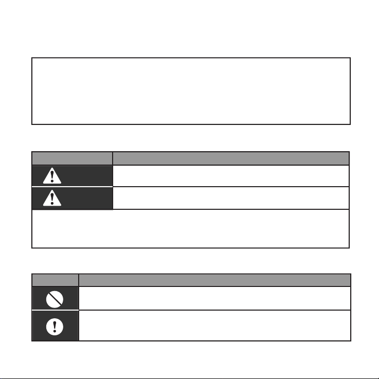
Identifier description
Identifier Meaning
W
arning
Means improper handling may lead to personal injury or
[Note]: 1. “Harm” means injury, burn and electric shock which need
long-term treatment but need no hospitalization
2. “Property loss” means loss of properties and materials.
Caution
Icon description
Meaninglcon
It indicates forbidding. The forbidden subject-matter is indicated in the
icon or by images or characters aside.
It indicates compulsory implementation. The compulsory subject-matter
is indicated in the icon or by images or characters aside.
Means improper handling may lead to personal death or
severe injury.
property loss.
1
Page 6
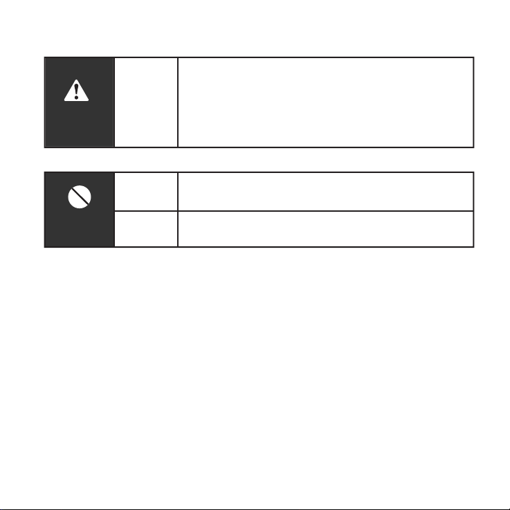
Warning
W
arning
Usage
W
arning
Delegate
arning
Usage
arning
installation
Forbid
Forbid
Please entrust the distributor or professionals to install
the unit. The installers must have the relevant know-how.
Improper installation performed by the user without perm
ission may cause fire, electric,shock, personal injury or
water leakage.
Do not spray flammable aerosol to the wire
controller directly. Otherwise, fire may occur.
Do not operate with wet hands or let water enter the wire
controller. Otherwise, electric shock may occur.
2. SUMMARIZE 3. FUNCTION SUMMARY
Usage condition:
1. Power supply: 5V DC.
2. Operation temperature:
-15°C~ +43°C(-5°F+109°F).
3. Operation humidity: 40%-90%,RH.
2
Main function:
1. Connecting to indoor unit by +5V, GND,
E, Y, X terminal;
2. Buttons setting action mode/ fan/ time/
temperature/ date etc.
3. LCD and background display.
4. Timer for every week.
5. Override function
6. Unified switch of ON/OFF
Page 7
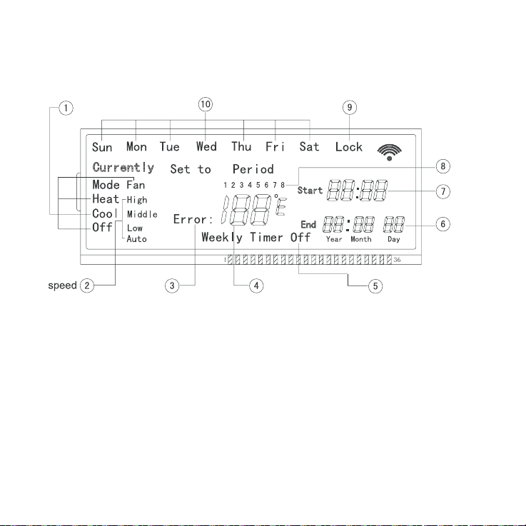
4. NAME AND FUNCTION OF LCD ON THE WIRE CONTROLLER
Operation mode
Error
ķOperation mode indication: When
press "MODE"button, the following mode
can be selected in circle: Cool→Heat→
Fan→Off.
For cooling only model, heat mode
should be skipped.
ĸFan speed indication :There are four
fan modes : auto, low, middle, high.For
some air conditioners with no middle fan,
then the middle fan is seen as high
Week
Lock
Period
Time
Date
Temperature
or Error code
speed.
ĹFault indication.
ĺTemperature or error code indication.
ĻWeekly Schedule Controller switch
indication.
ļDate indication.
ĽTime indication.
ľPeriod indication.
ĿLock indication.
ŀWeek indication.
Timer on/off
3
Page 8
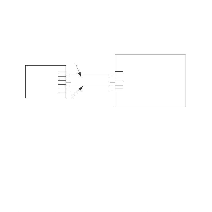
5. INSTALLATION METHOD
When a weekly schedule controller is needed, a small 2-cores wire and
3-cores wire should be added. Connect like the following figure.
Weekly Schedule
Controller
4
Yel lo w
Brown
Black
Red
White
2-cores wire
+5V
GND
E
Y
X
3-cores wire
To display board
To main board
+5V
GND
E
Y
X
INDOOR UNIT
Page 9

6. NAME AND OPERATION OF THE BUTTON ON THE
WIRE CONTROLLER
212))
23(5$7,21/$03
'(/$<
'(/$<
ķMode button: press this button, then
the operation mode will change in turn as
follows: COOL→HEAT→FAN→OFF
Remark : For the cooling only model, the
heating mode should be skipped.
ĸFan speed button: press this button,
then the operation fan will change in turn
as follows: Auto→Low→Middle→High
ĹEdit button: press this button, then you
can setup Weekly time function. (Details
in page 9: SET PLAN_ķ)
5
Page 10

ĺDate button: press the button, and
then enter the date of calibration, the
calibration sequence year--month--day-
-week .
Jump to next setparameters when press
the Confirm button every time, set the
scope of date (1-31) is not checking it
without date. (Press Cancel that can
return to the previous parameter
changes)
ĻTimer on/off button:Press this button,
can turn off the weekly timer function.
ļReset button:When press this button,
the system will clear the information of
weekly timer and delay,come into normal
display state and need to carry out some
initial setting (in page 9: SET PLAN_ĸ).
ĽLock button:press this button,weekly
timer come into lock mode, Press LOCK
again,lock mode is unchained at once.
Weekly timer lock mode state can not be
canceled when weekly timer has come
back to supply power after interruption of
power supply.
ľCancel button: It is for not saving and
retreating, or to cancel the temporary
6
setting (Details in page 10).
ĿQuery button: Press “Query”, display
present indoor temperature value, press
“Cancel” to back press “Add ” or
“Reduce” to select the day you want to
query from “Sun” to “Sat”, press
“Confirm”. Then press “Add ” or
“Reduce” to select the period you want to
query from “1”“4” period. Press
“Cancel” to back or select other periods.
ŀReduce button: It is for reducing to
numbers and moving left or up to the
other.
Add button: It is for adding to numb
ers, and moving right or down to the
other.
Confirm button: It is for confirm
selection.
Time button: press this button, then
press "Add" or "Reduce" to adjust the
hours valueˈpress "Confirm" to adjust
minutes: press "Add" or "Reduce" to
adjust the minutes valueˈpress
"Confirm" to save and back.
Page 11

Delay button:
press this button once, display
" "
and
wait 3 seconds to confirm. It means the
unit will override 1 hour;
press this button twice, display
" "
and
wait 3 seconds to confirm. It means the
unit will override 2 hours;
" "
press three times, display
and wait
3 seconds to confirmIt means to cancel
the setting;
cycling display as follows: 1h-2h-0h-1h.
When the override function does not go
into effect, the delay time can be
changed through the setting. But if the
function has gone into effect, any opera-
tion for the delay button is not effective
and the delay button is only for querying
the delay time you set.
Remark :
button is ineffective.
ON/OFF button:
If weekly timer is off, delay
Push the button at the condition of OFF,
the OPERATION lamp lights, and the
wire controller enters into ON operation,
simultaneously sends the information of
operation mode, fan speed, temperature
etc.
Push the button at the condition of ON,
the OPERATION lamp extinguishes,
simultaneously sends the OFF. If having
set DELAY, the wire controller will cancel
this setting before entering into OFF,
close the concern indicator, and then
send the OFF information.
7. USING METHOD
SET TIME
Under the normal display interface
TIME
or
ADD
CONFIRM
NOTE
In operating, Press the key "CANCEL",
to turn back to the previous step or the
normal display interface.
REDUCE
ADD
set minute
set hour
REDUCE
or
CONFIRM
set done
7
Page 12

SET DATE
QUERY PLAN
Under the normal display interface
DATE
or
ADD
CONFIRM
ADD
CONFIRM
ADD
CONFIRM
ADD
CONFIRM
or
or
or
set done
REDUCE
REDUCE
REDUCE
REDUCE
set year
set month
set date
set week
Under the normal display interface
QUERY
or
ADD
CONFIRM
ADD
CONFIRM
CANCEL
or
display various parameters
of the selected period
CONFIRM
select week
REDUCE
REDUCE
select period
back to the normal
display interface
NOTE
In operating, Press the key "CANCEL",
to turn back to the previous step or the
normal display interface.
8
Page 13

SET PLAN
ʏ
Under the normal display interface
or
or
or
or
CONFIRM
REDUCE
REDUCE
REDUCE
REDUCE
*
EDIT
ADD
CONFIRM
ADD
CONFIRM
ADD
CONFIRM
ADD
CONFIRM
ʐ
RESET
ADD
select °C or °F
select week
select the start
hour of the first
period
select the start
minute of the first
period
select the end
hour of the first
period
select the end
ADD
or
CONFIRM
CONFIRM
Setting of the first period is done
Long time press the button
"CONFIRM" to turn back to the
"select week" interface directly
ADD
*
set various parameters of the next period
from the place " ", till the setting of
parameters of all the four period is done,
turn back to the "slect week" interface, as
this time, you can also press the key
"CANCEL"back to the normal display
interface.
minute of the first
REDUCE
period
or
*
REDUCE
NOTE
In operating, Press the key "CANCEL",
to turn back to the previous step or the
normal display interface.
9
Page 14

How to change “ ” to “ ”,or “ ”
to “ ” ?
There are two methods:
ʏ
Reset
ADD
select °C or °F
CONFIRM
Pressing the “RESET” button will
clear the information of weekly timer.
ʐ
EDIT
Always press
QUERY
+
select °C or °F
The example of DELAY
The plan setted as follows:
period
Start time
End time
Time
Period 1
Period 2
09:00
11: 30
If you want the unit overrides 1/2 hour after
period 1. Just press “ Delay ” button once
during 09:00 to 11:30.
But if you set the delay time(1/2 hour) out
of the period you set (like during 11:31 to
14:30), the unit will override 1/2 hour at once.
Remark:When finishing the function, the
unit will operate following the plan you set.
14:30
17:30
Period 3
19:00
21:30
Period 4
00:00
00:00
How to set mode/fan/temperature
under the OFF status?
Firstly, press the Mode button to enter the
setting. Then it will display the mode/ fan/
temperature before OFF. At this time, you
could set the mode/ fan/ temperature you
want.
And When you finish the setting, press the
Confirm button to send. The air conditioner
will start with the information you set.
What is the temporary setting?
ķ
Weekly timer is operating:
When the unit operated with the Weekly
timer, Any operations of mode/ fan speed/
temperature are called temporary setting.
When the wire controller displays Currently
icon, temporary setting has been effective.
Under the main interface, pressing “cancel”
button will cancel the temporary setting.
“ Currently ” icon will disappear and the
mode/ fan speed/ temperature parameters
of temporary setting will be saved. Then the
unit operated with the Weekly timer.
ĸ
Weekly timer is off:
Temporary setting is always effective.
10
Page 15

8. TECHNICAL INDICATION AND REQUIREMENT
EMI and EMC comply to CE
9. TABLE OF ALARM STATES
Alarm states
EF
EE
ED
EA
E8
E7
E6
E8
E5
E4
E2
E1
E0
F1
NOTE:
When the unit appears error, the corresponding error code
will be displayed with the flashing OPERATION LAMP.
Description
Other malfunctions
Water level detection malfunction
Outdoor malfunction protection
Compressor overcurrent˄4 times˅
Air speed detection out of control
EEPROM error
Zero-crossing detection error
Malfunction in air discharge temperature sensor of T3, T4 or digital
compressor
T2B Sensor malfunction
T2A Sensor malfunction
T1 Sensor malfunction
Communication malfunction
Phases' sequence error or default
Weekly schedule Sensor malfunction
11
Page 16

10. TABLE OF PROTECTION STATES
Protection states
PF
P8
P7
P6
P5
P4
P3
P2
P1
P0
12
Description
Other protection
Compressor overcurrent
Power supply over-under voltage protection
Air exhaust low pressure protection
Air exhaust high pressure protection
Air exhaust temperature protection
Compressor temperature protection
Condensate high temperature
protection
Anti-cool air or defrost protection
Evaporator temperature protection
Page 17

Page 18

Version: MDV12U-004AW
202055100846
Page 19

Page 20

Page 21

Page 22

Page 23

Page 24

 Loading...