

Page 1
1
OWNER’ S MANUAL
CENTRAL MONITOR CONTROL
MD-CCM02/E
Thank you very much for purchasing our product.
Before using your unit, please read this manual carefully and keep it for future
reference.
Page 2

2
This manual gives detailed description of the precautions
that should be brought to your attention during operation.
In order to ensure correct service of the wired controller
please read this manual carefully before using the unit.
For convenience of future reference, keep this manual
after reading it.
Page 3

3
CONTENTS
1. SAFETY PRECAUTION ............................................................................. 1
2. SUMMARIZE OF OUTDOOR CCM ........................................................... 2
3. BASIC REQUIREMENTS ........................................................................... 3
4. OPERATION .............................................................................................. 3
5. INSTALLATION ....................................................................................... 10
6. TECHNICAL INDEX AND REQUIREMENT ..............................................11
Page 4
1
1. SAFETY PRECAUTIONS
The following contents are stated on the product and the operation manual,
including usage, precautions against personal harm and property loss, and the
methods of using the product correctly and safely. After fully understanding the
following contents (identiers and icons), read the text body and observe the
following rules.
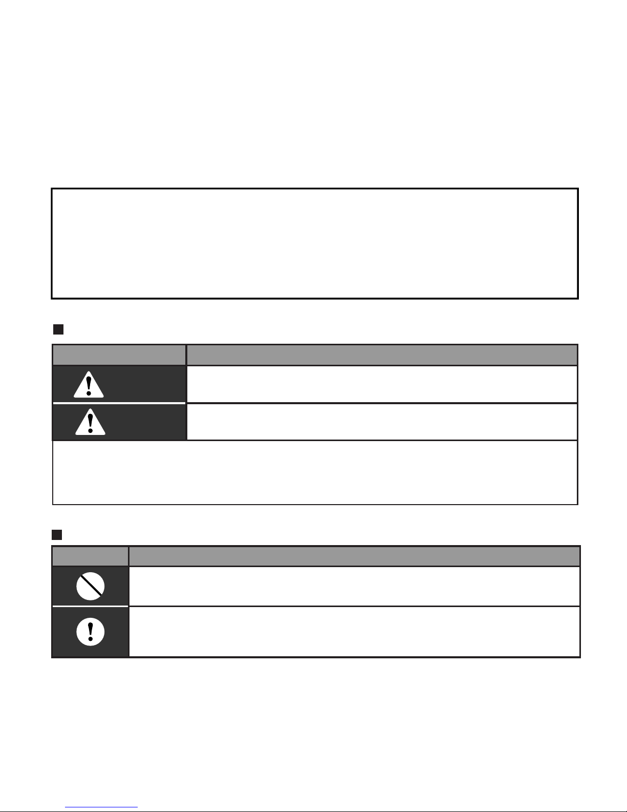
Identier description
Icon description
Identier Meaning
Warning
Means improper handling may lead to personal or
severe injury.
Caution
Means improper handling may lead to personal injury or
property loss.
[Note]: 1. “Harm” means injury, burn and electric shock which need
long-term treatment but need no hospitalization
2. “Property loss” means loss of properties and materials.
lcon Meaning
It indicates forbidding. The forbidden subject-matter is indicated in the
icon or by images or characters aside.
It indicates compulsory implementation. The compulsory subject-matter
is indicated in the icon or by images or characters aside.
Page 5
2
2. SUMMARIZE OF OUTDOOR CCM
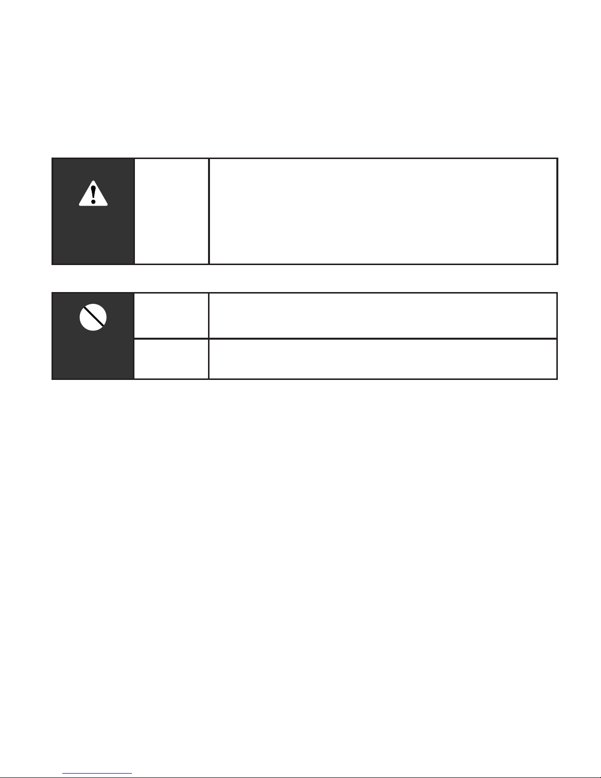
Warning
Warning
Delegate
installation
Please entrust the distributor or professionals to install
the unit. The installers must have the relevant know-how.
Improper installation performed by the user without
permission may cause re, electric, shock, personal
injury or water leakage.
Usage
Warning
Forbid
Do not spray ammable aerosol to the wire controller
directly. Otherwise, re may occur.
Forbid
Do not operate with wet hands or let water enter the wire
controller. Otherwise, electric shock may occur.
The functions only can be realized when
the system is in normal operation.
1. Central Control Monitor can realize
the central control and data query to
outdoor units. One outdoor CCM can
connect max 8 refrigerant system by
NIM, so each outdoor CCM can connect
max 8 systems are multiplied by max
4 sets outdoor units per system equals
max 32 outdoor units. And it adopts
wire-connecting method communication
to realize central control to the outdoor
units in the same network. .
2. CCM can communicate with PC
through RS485/RS232 converter.
One PC can connect max. 16 outdoor
CCM and 16 indoor CCM. And PC can
realize central control to outdoor units,
central control to indoor units, central
control to indoor units and outdoor units,
management, status query and so on.
Page 6

3
3. The CCM and outdoor units, PC and
CCM adopt main-auxiliary responsion
communication. In the network of CCM
and outdoor units, CCM is the main unit
and outdoor units are the auxiliary units.
3. BASIC REQUIREMENTS
1. Applicable Power Voltage Range:
Input Voltage 220~240VAC.
2. AC Input Power Frequency:
50Hz/60Hz.
3. Working Ambient Temp.:
-15°C(-5°F)~ +43°C(+109°F).
4. Working Ambient Humidity: RH40%~
RH90%.
4. OPERATION
4-1 Key Words and Basic Functions
Power on or restore
After the CCM is power on or restore,
rst all display segment on LCD will be
on and last 3 seconds, then all will be
off. 2 second later, the system enters
into normal display state, the CCM is in
the main page and display the data in
the rst page.
Network Area Address Setting
The PC or gateway can connect max. 16
sets CCM. Every CCM can be viewed as
one network area and be distinguished
by address set through the address
setting button in keyboard. The setting
range is 16-31.
Address setting method:
pressing the Address set button
repeatedly, the address will be increased
one by one. When the address is equal
MAX.31 and you press once more, the
address will restart from 16.
Indicator Display
Indicator lamp will be on when the CCM
is power on.
CCM LOCKED
All the other button will not be on
controlled anytime when pushing the
CCM is locked, and unlock happens
when receiving the lock!
Page 7

4
Electric energy consumption query
The Electric energy consumption can be
queried through CCM when the outdoor
unit has its ammeter.
4-2 Function
4-2-1 Buttons on CCM
1. QUERY BUTTON
Push it to enter into the query state.
2. PREVIOUS BUTTON
On the query state, push it to query in
default the running states of other online
air-conditioners.
3. NEXT BUTTON
On the query state, push it to query in
default the running states of other online
air-conditioners.
QUERY
SET
MODE
PREVIOUS PAGE UP
NEXT
PAGE DOWN
ADDRESS
Graph 1 Button Distribution on CCM
LOCK
OK
M
Page 8

5
4. PAGE UP BUTTON
Pushing the PAGE UP button when
choosing a online air-conditioner on the
query state can display the parameters
in previous page, and this can be cycled.
5.PAGE DOWN BUTTON
Pushing the PAGE DOWN button when
choosing a online air-conditioner on the
query state can display the parameters
in next page, and this can be circled.
6. SET BUTTON
Press SET button to enter into Set
Page.
7. MODE BUTTON
Pressing MODE button to enter into
MODE set, and select circularly between
Forced Cooling and OFF state.
8. OK BUTTON
Pressing OK button to conrm all
settings and send to the corresponding
air-conditioners.
9. LOCK BUTTON
All the other button will not be on
controlled anytime when pushing the
button, and unlock happens when push
it again.
10. ADDRESS SET BUTTON
In set page, pressing the SET button
repeatedly, the address will be increased
one by one. When the address is equal
31 and you press once more, the
address will restart from 16.
Page 9

6
Common Display Data:
1.Figure means CCM is sending
query order;
2.Figure means CCM is in
communication connection with PC,
and it will be off in 20 seconds with no
communication;
3.Figuer means CCM is in
communication connection with outdoor
unit, and it will be off in 20 seconds with
communication
4.Press the OK button in setting page
and waiting for 4 seconds,"success"or
"fail" will be shown in the operation state
area.;
Stand-by Page Display:
1.Figure means the total number
of online modules;
2.Figure means the total number
of online outdoor units;
4-2-2 Datas
Graph 2 LCD Screen
OR display
' '
with the model: MD-CCM02/E(H)
Page 10

7
3.Stand-by Page can display the address
of CCM with the address format of "Addr
xx", here "xx" equals the real address
of CCM plus 16, so the range of "xx" is
16-31.
Query Page Display
1.Query Page Display the symbol of
query;
2.Displaying the address of selected
outdoor unit with and .
3.Mode display: means cool,
means heat, means shut off,
means locked cool, means locked
heat.
4.Fan Speed Display: means low
speed, means middle speed,
means high speed.
5.Compressor State Display: “COMP. 1
2 3 4 ”;
6.Electromagnetism Valve Display:
“EMV. 1 2 3 4 5 6”;
7.4-Ways Valve Display: ;
8.Defrost Display: “Defrost”;
9.Oil Return Display: “OIL RETURN”;
10.Page0 displays the consumption
of electric energy with: "ELECTRIC
ENERGY Kwh" and the number;
11.Page1 displays the input power
frequency with “Frequency Hz” and the
number;
12.Page2 displays the total number of
indoor units;
13.Page3 displays the temperature
symboled T3;
14.Page4 displays the temperature
symboled T4;
15.Page5 displays the temperature
symboled T6;
16.Page6 displays the discharge
temperature of compressor symboled
C1;
17.Page7 displays the discharge
temperature of compressor symboled
C2;
Page 11

8
18.Page8 displays the discharge
temperature of compressor symboled
C3 ;
19.Page9 displays the compressor
current symboled 1 with"CURRENT A",
"1" and the number;
20.Page10 displays the compressor
current symboled 2 with "CURRENT A",
"2" and the number;
21.Page11 displays the compressor
current symboled 3 with "CURRENT A",
"3" and the number;
22.Page12 displays the digital capacity
with "DIGITAL CAPACITY" and the
number;
23.Page13 displays the openness of
electromagnetism valve symboled 1
with "VALVE OPENNESS" , "1" and the
number;
24.Page14 displays the openness of
electromagnetism valve symboled 2
with "VALVE OPENNESS", "2" and the
number;
25.Page15 displays the most advanced
malfunction with "MALFUNCTION" and
the code;
26.Page16 displays the most advanced
protection with "PROTECTION" and the
code.
The page will increase or decrease by
1 every time you press “PAGE UP” or
“PAGE DOWN”.
Select the online outdoor unit by push
the “previous” or “next” freely.
• SET PAGE DISPALY
1.Set Page Displays "set";
2.Mode display:Pressing MODE button
to enter into MODE set, and select
circularly between Forced Cooling
and state;
3.Set page displays the addresses of
selected outdoor unit and module;
4.Pressing OK button to confirm all
settings and send to the corresponding
NOTE
Page 12

9
air-conditioners.
5."successful"or "unsuccessfull" shown
in the operation state area indicates
whether the transmission is conrmed or
not.
4-3 Malfunction and Protection Code Table
ERROR Code ERROR Contents Description ERROR Code ERROR Contents Description
H3
Outdoor adding malfunction
(valid for host unit)
PA Defrost Protection
H2
Outdoor decreasing
malfunction (valid for host unit)
P8
Compressor Current 3rd
Protection
H1
Net communication
malfunction
P7
Compressor Current
2nd Protection
EF Other malfunction P5
Condenser High Temp.
Protection
E4T4 Temp. Sensor malfunction P4
Discharge Pipe Temp.
Protection
E3T3 Temp. Sensor malfunction P3
Compressor Current 1st
Protection
E2 Sensor malfunction P2
Discharge Low-pressure
Protection
E1
Phase sequence or lack of
phase
P1
Discharge Highpressure Protection
E0 Communication malfunction P0
Compressor High Temp.
Protection
PF Other Protection
PE Oil Balance
PD Oil Return
Page 13

10
5. INSTALLATION
1. Never connect the network communication wire with strong power or put it into the
same wiring tube with the strong power. And at least 300-500mm distance should be left
between their wiring tubes.
2. The shield cable must be connected stable to the ground, or transmission may fail.
3. Do not attempt to extend the shield cable by cutting.
4. After finishing connection, do not use Megger to have the insulation check to the
signal wire.
Turn a screwdriver at the concave on bottom panel
of the Wire Controller to remove the Back Cover
When installing the Wire Controller, you
should adjust the bottom of the Wire Controller
Board to the Wire Controller Back Cover which
should be xed rst, then press the other end
of the Wire Controller Board.
When installing the Wire Controller
Cover, be sure there is a hole
in the wall to avoid the Wire
Controller Back Cover being xed
directly to the wall which is not
allowed for the Wire Joint extrudes
out of the Wire Controller Back
Cover
Wire Controller
Back Cover
Wire Controller
Top Cover
Wire Controller
LCD
Wire Controller
Board
Wire Controller
Bottom Cover
Wood Mounting
Screw (M4X20)
Page 14

11
6. TECHNICAL INDEX AND REQUIREMENT
EMC and EMI should conform to the requirement of CE Certication.
Page 15

12
Version: MDV06U-001IW
202000170150
Page 16

 Loading...