

Midea MEHSU-18CHC2, MEHSU-09CHC2, MEHSU-18CHD2, MEHSU-18CHF2, MEHSU-24CHC2 Service Manual
...Page 1

CONTENTS
1. Precaution ..................................................................................................................................................... 1
1.1 Safety Precaution .......................................................................................................................... 1
1.2 Warning .......................................................................................................................................... 1
2. Part Names and Features ............................................................................................................................ 4
2.1 Model Names of Indoor/Outdoor units .......................................................................................... 4
2.2 Part names of Indoor/Outdoor units .............................................................................................. 5
2.3 Features ......................................................................................................................................... 9
3. Dimension ................................................................................................................................................... 18
3.1 Indoor Unit ................................................................................................................................... 18
3.2 Outdoor Unit ................................................................................................................................ 23
4. Service Space ............................................................................................................................................. 25
4.1 Indoor Unit ................................................................................................................................... 25
4.2 Outdoor Unit ................................................................................................................................ 27
5. Refrigerant Cycle Diagram ........................................................................................................................ 28
6. Wiring Diagram ........................................................................................................................................... 29
6.1 Indoor Unit ................................................................................................................................... 29
6.2 Outdoor Unit ................................................................................................................................ 34
7. Fan Curves .................................................................................................................................................. 41
8 Electric Characteristics .............................................................................................................................. 48
9 Sound Level ................................................................................................................................................. 49
9.1 Indoor unit .................................................................................................................................... 49
9.2 Outdoor unit ................................................................................................................................. 52
10 Accessories ............................................................................................................................................... 53
11 The Specification of Power ...................................................................................................................... 55
12 Installation Details .................................................................................................................................... 57
12.1 Location selection ................................................................................................................... 57
12.2 Indoor unit installation ............................................................................................................. 57
12.3 Outdoor unit installation .......................................................................................................... 64
12.4 Refrigerant pipe installation .................................................................................................... 65
12.5 Drainage pipe installation ....................................................................................................... 69
12.6 Vacuum Drying and Leakage Checking ................................................................................. 72
12.7 Additional refrigerant charge .................................................................................................. 73
12.8 Engineering of insulation ........................................................................................................ 74
12.9 Engineering of electrical wiring ............................................................................................... 75
12.10 Test operation ...................................................................................................................... 75
13. Operation Characteristics ....................................................................................................................... 77
14. Electronic Function .................................................................................................................................. 78
14.1 Abbreviation ............................................................................................................................... 78
Page 2

14.2 Display function ......................................................................................................................... 78
14.3 Main Protection .......................................................................................................................... 78
14.4 Operation Modes and Functions ............................................................................................... 79
16. Troubleshooting ....................................................................................................................................... 85
16.1 Indoor Unit Error Display ........................................................................................................... 86
16.2 Outdoor unit error display .......................................................................................................... 87
For 9K-24K outdoor unit: ................................................................................................................... 87
For 36K-48K Outdoor Unit ................................................................................................................. 88
Outdoor check function ...................................................................................................................... 88
16.3 Diagnosis and Solution .............................................................................................................. 91
16.4 Main parts check ...................................................................................................................... 107
17. Disassembly Instructions ..................................................................................................................... 114
17.1 Indoor unit ................................................................................................................................ 114
17.2 Outdoor unit ............................................................................................................................. 131
Page 3

1
1. Precaution
1.1 Safety Precaution
To prevent injury to the user or other
people and property damage, the following
instructions must be followed.
Incorrect operation due to ignoring
instruction will cause harm or damage.
Before service the unit, be sure to
read this service manual at first.
1.2 Warning
Installation
Do not use a defective or underrated
circuit breaker. Use this appliance on a
dedicated circuit.
There is risk of fire or electric shock.
For electrical work, contact the dealer,
seller, a qualified electrician, or an
authorized service center.
Do not disassemble or repair the product,
there is risk of fire or electric shock.
Always ground the product.
There is risk of fire or electric shock.
Install the panel and the cover of
control box securely.
There is risk of fire of electric shock.
Always install a dedicated circuit and
breaker.
Improper wiring or installation may cause
electric shock.
Use the correctly rated breaker of
fuse.
There is risk of fire or electric shock.
Do not modify or extend the power
cable.
There is risk of fire or electric shock.
Do not install, remove, or reinstall the
unit by yourself (customer).
There is risk of fire, electric shock, explosion,
or injury.
Be caution when unpacking and
installing the product.
Sharp edges could cause injury, be especially
careful of the case edges and the fins on the
condenser and evaporator.
For installation, always contact the
dealer or an authorized service center.
Do not install the product on a
defective installation stand.
Be sure the installation area does not
deteriorate with age.
If the base collapses, the air conditioner could
fall with it, causing property damage, product
failure, and personal injury.
Do not let the air conditioner run for a
long time when the humidity is very high
and a door or a window is left open.
Take care to ensure that power cable
could not be pulled out or damaged during
operation.
There is risk of fire or electric shock.
Do not place anything on the power
cable.
There is risk of fire or electric shock.
Do not plug or unplug the power
supply plug during operation.
There is risk of fire or electric shock.
Do not touch (operation) the product
with wet hands.
Do not place a heater or other
appliance near the power cable.
There is risk of fire and electric shock.
Do not allow water to run into
electrical parts.
It may cause fire, failure of the product, or
electric shock.
Do not store or use flammable gas or
combustible near the product.
There is risk of fire or failure of product.
Do not use the product in a tightly
closed space for a long time.
Oxygen deficiency could occur.
When flammable gas leaks, turn off
the gas and open a window for ventilation
before turn the product on.
Page 4

2
If strange sounds or smoke comes
from product, turn the breaker off or
disconnect the power supply cable.
There is risk of electric shock or fire.
Stop operation and close the window
in storm or hurricane. If possible, remove
the product from the window before the
hurricane arrives.
There is risk of property damage, failure of
product, or electric shock.
Do not open the inlet grill of the
product during operation. (Do not touch the
electrostatic filter, if the unit is so equipped.)
There is risk of physical injury, electric shock,
or product failure.
When the product is soaked, contact
an authorized service center.
There is risk of fire or electric shock.
Be caution that water could not enter
the product.
There is risk of fire, electric shock, or product
damage.
Ventilate the product from time to
time when operating it together with a stove
etc.
There is risk of fire or electric shock.
Turn the main power off when
cleaning or maintaining the product.
There is risk of electric shock.
When the product is not be used for a
long time, disconnect the power supply plug
or turn off the breaker.
There is risk of product damage or failure, or
unintended operation.
Take care to ensure that nobody
could step on or fall onto the outdoor unit.
This could result in personal injury and
product damage.
CAUTION
Always check for gas (refrigerant)
leakage after installation or repair of
product.
Low refrigerant levels may cause failure of
product.
Install the drain hose to ensure that
water is drained away properly.
A bad connection may cause water leakage.
Keep level even when installing the
product.
It can avoid vibration of water leakage.
Do not install the product where the
noise or hot air from the outdoor unit could
damage the neighborhoods.
It may cause a problem for your neighbors.
Use two or more people to lift and
transport the product.
Do not install the product where it will
be exposed to sea wind (salt spray) directly.
It may cause corrosion on the product.
Corrosion, particularly on the condenser and
evaporator fins, could cause product
malfunction or inefficient operation.
Operational
Do not expose the skin directly to
cool air for long time. (Do not sit in the
draft).
Do not use the product for special
purposes, such as preserving foods, works
of art etc. It is a consumer air conditioner,
not a precision refrigerant system.
There is risk of damage or loss of property.
Do not block the inlet or outlet of air
flow.
Use a soft cloth to clean. Do not use
harsh detergents, solvents, etc.
There is risk of fire, electric shock, or damage
to the plastic parts of the product.
Do not touch the metal parts of the
product when removing the air filter. They
are very sharp.
Do not step on or put anything on the
product. (outdoor units)
Always insert the filter securely.
Clean the filter every two weeks or more
often if necessary.
A dirty filter reduces the efficiency of the air
conditioner and could cause product
malfunction or damage.
Page 5

3
Do not insert hands or other objects
through air inlet or outlet while the product
is operated.
Do not drink the water drained from
the product.
Use a firm stool or ladder when
cleaning or maintaining the product.
Be careful and avoid personal injury.
Replace the all batteries in the remote
control with new ones of the same type. Do
not mix old and new batteries or different
types of batteries.
There is risk of fire or explosion.
Do not recharge or disassemble the
batteries. Do not dispose of batteries in a
fire.
They may burn of explode.
If the liquid from the batteries gets
onto your skin or clothes, wash it well with
clean water. Do not use the remote of the
batteries have leaked.
Page 6
4
2. Part Names and Features
2.1 Model Names of Indoor/Outdoor units
Series Capacity
Indoor units
Outdoor units
Cassette
9K
MEHSU-09CHC2
MCHSU-09PHH2
Duct
MEHSU-09CHD2
Console
MEHSU-09CHN2
Cassette
12K
MEHSU-12CHC2
MCHSU-12PHH2
Duct
MEHSU-12CHD2
Console
MEHSU-12CHN2
Cassette
18K
MEHSU-18CHC2
MCHSU-18PHH2
Duct
MEHSU-18CHD2
Floor Ceiling
MEHSU-18CHF2
Cassette
24K
MEHSU-24CHC2
MCHSU-24PHH2
Duct
MEHSU-24CHD2
Floor Ceiling
MEHSU-24CHF2
Cassette
36K
MEHSU-36CSC2
MCHSU-36CSH2
Duct
MEHSU-36CSD2
Floor Ceiling
MEHSU-36CSF2
Cassette
48K
MEHSU-48CSC2
MCHSU-48CSH2;
Duct
MEHSU-48CSD2
Floor Ceiling
MEHSU-48CSF2
Page 7
5
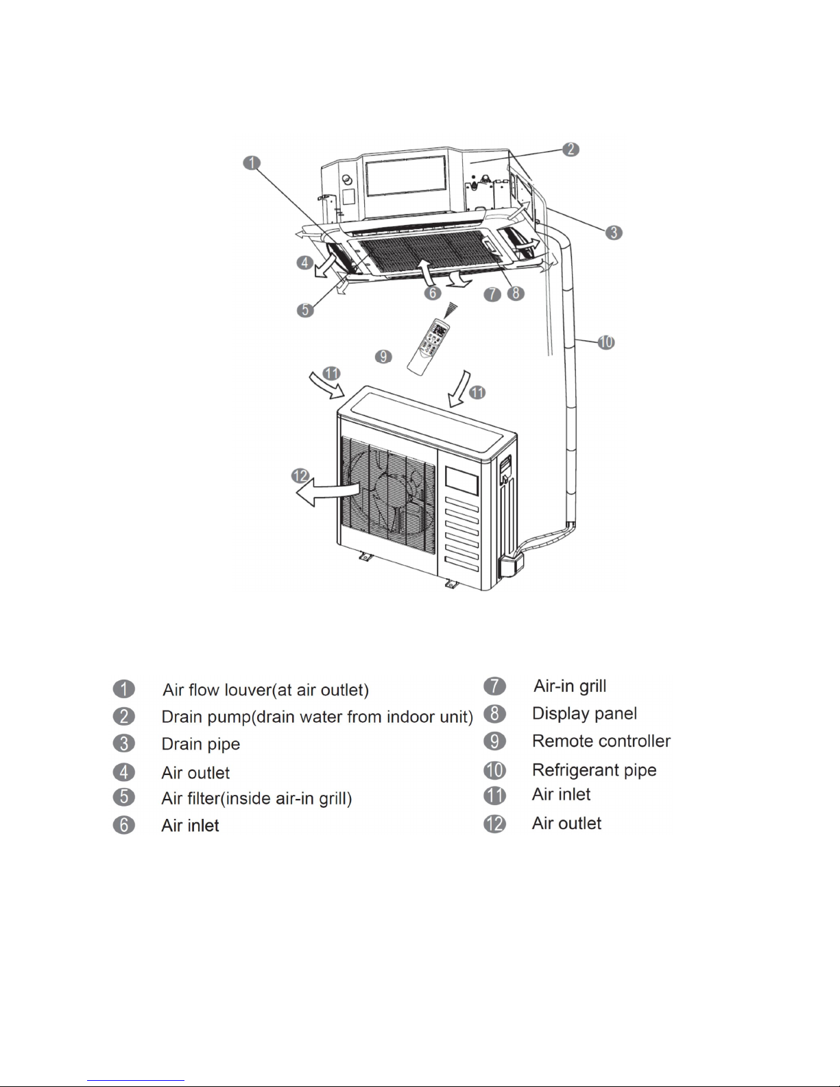
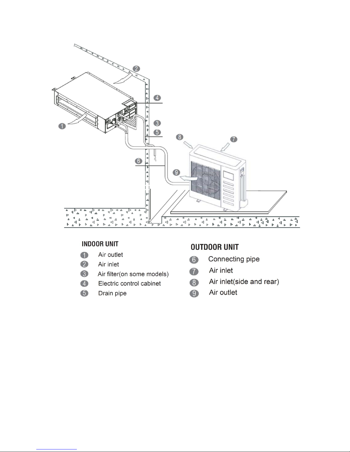
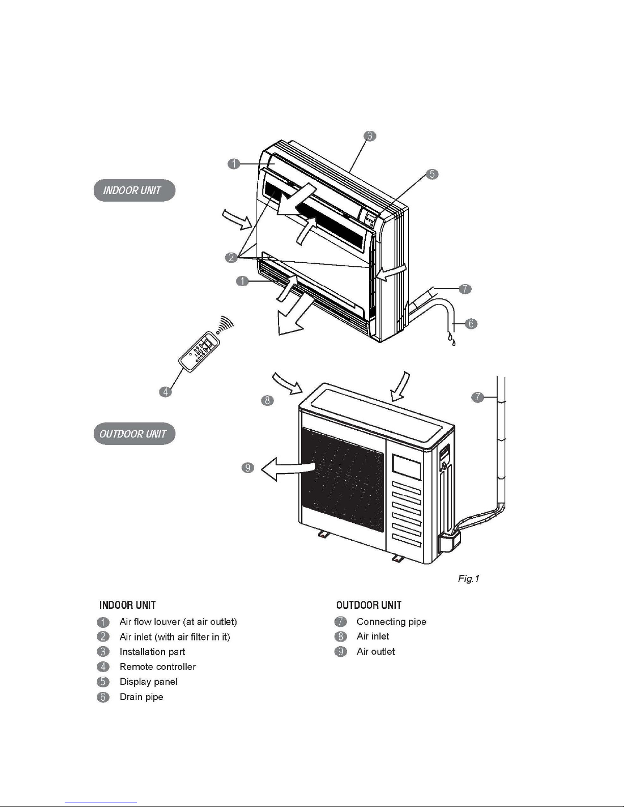
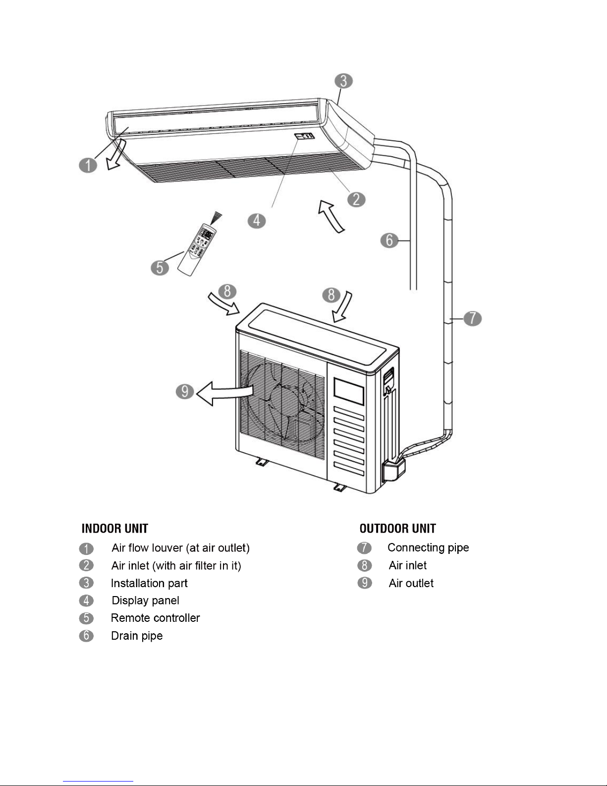
2.2 Part names of Indoor/Outdoor units
Cassette Unit
Page 8
6
Duct Units
Page 9
7
Console
Page 10
8
Ceiling-floor Units
Page 11
9
2.3 Features
2.3.1 Duct Units
2.3.1.1 Installation Accessories: (Optional)
Front Board, Canvas Air Passage, Filter, Panel, for easy installation
2.3.1.2 Easy Installation: Two air Inlet Styles (Bottom side or Rear side)
Air inlet from rear is standard for all capacity; air inlet from bottom is optional.
The size of air inlet frame from rear and bottom is same, it’s very easy to move the cover from
bottom to rear side, or from rear to the bottom, in order to matching the installation condition.
2.3.1.3 Fresh Air Intake Function
Install one duct from the reserved fresh-air intake to outdoor.
Continually inhale the fresh air to improve the quality of the indoor air, fulfills air quality more
healthy and comfortable.
Panel
Air intake from rear (Standard)
Air intake from bottom (Optional)
6.30in
4.92in
3.15in
3.54in
Page 12
10
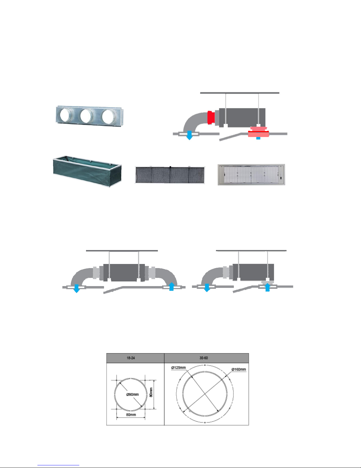
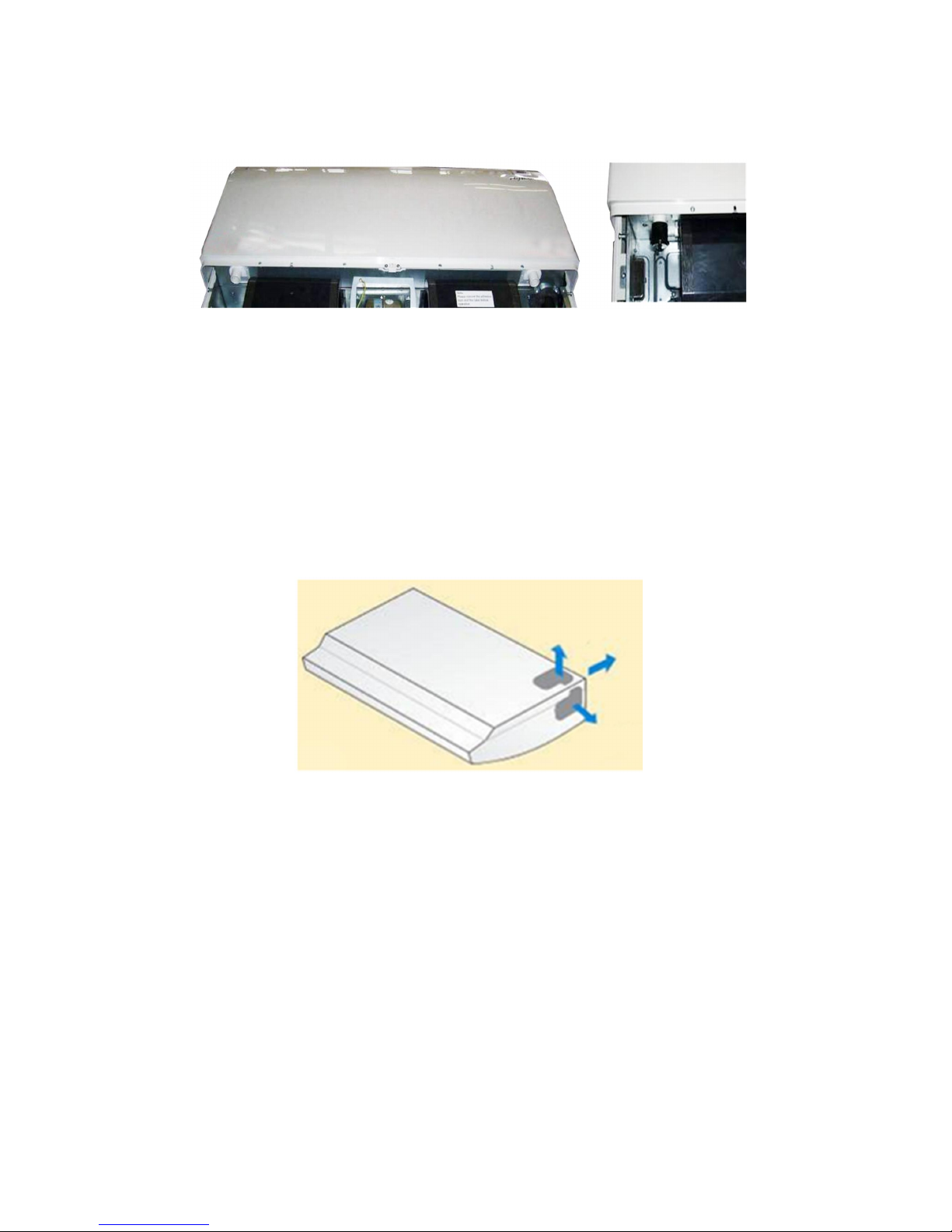
2.3.1.4 Easy Maintenance
Clean the filter (Optional, standard product without filter)
It is easy to draw out the filter from the indoor unit for cleaning, even the filter is installed in rear
side or bottom side.
Replace the motor or centrifugal fan
Remove the ventilated panel firstly. Remove a half of blower housing and take out the motor with
centrifugal fan. Directly remove two bolts, and then replace the motor or centrifugal fan easily.
2.3.1.5 Reserved Remote On-off and Central Control Ports
Reserved remote on-off ports and central control ports, can connect the cable of an on-off
controller or a central controller to realize remote on-off control function or group control function.
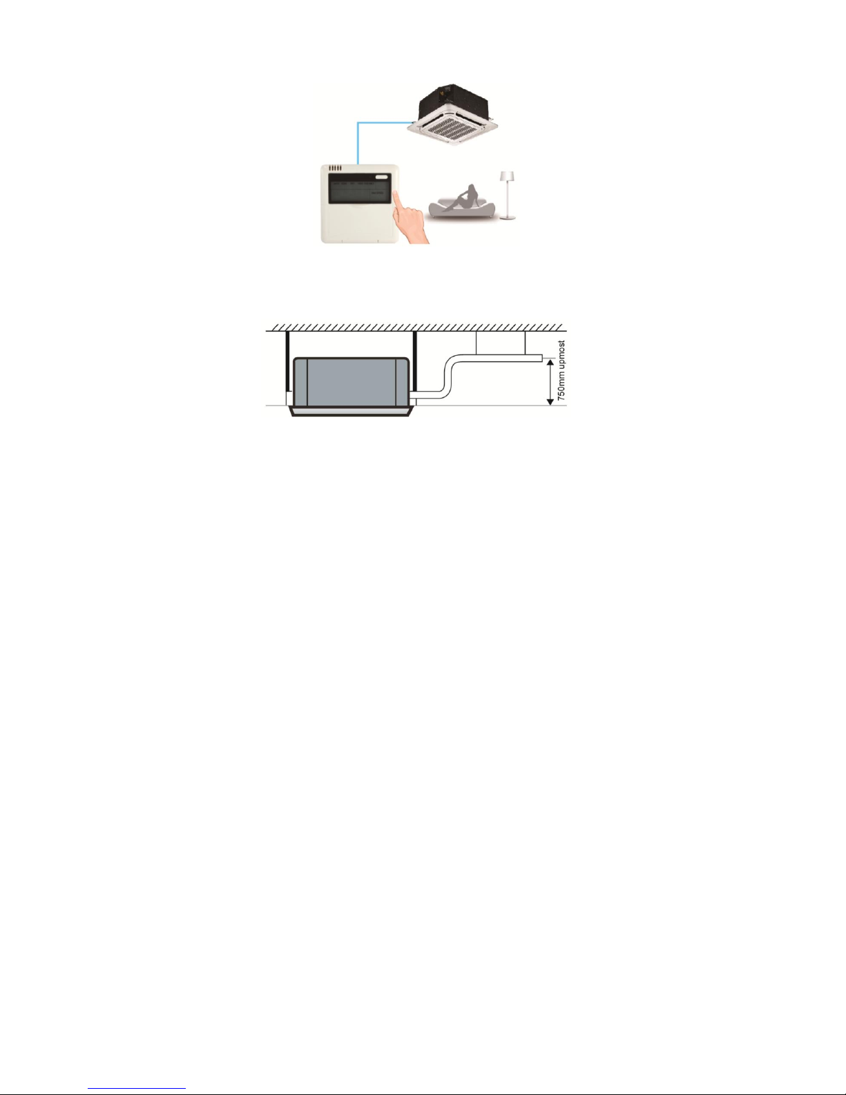
2.3.1.6 Built-in Drain Pump (Optional):
Built-in drain pump can lift the water to 750mm(29.53in) upmost. It’s convenient to install drainage
piping under most space condition.
Motor
Blower Housing
Ventilated Panel
Remote on-off ports Central control ports
Page 13
11
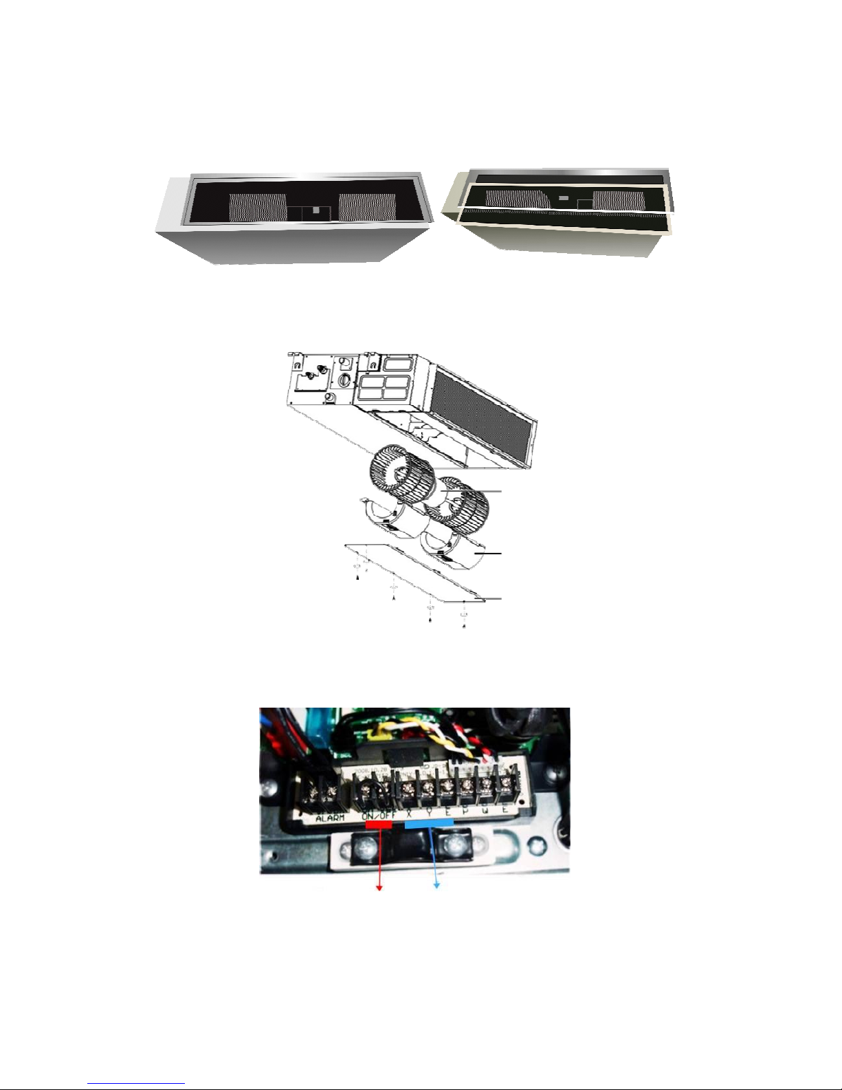
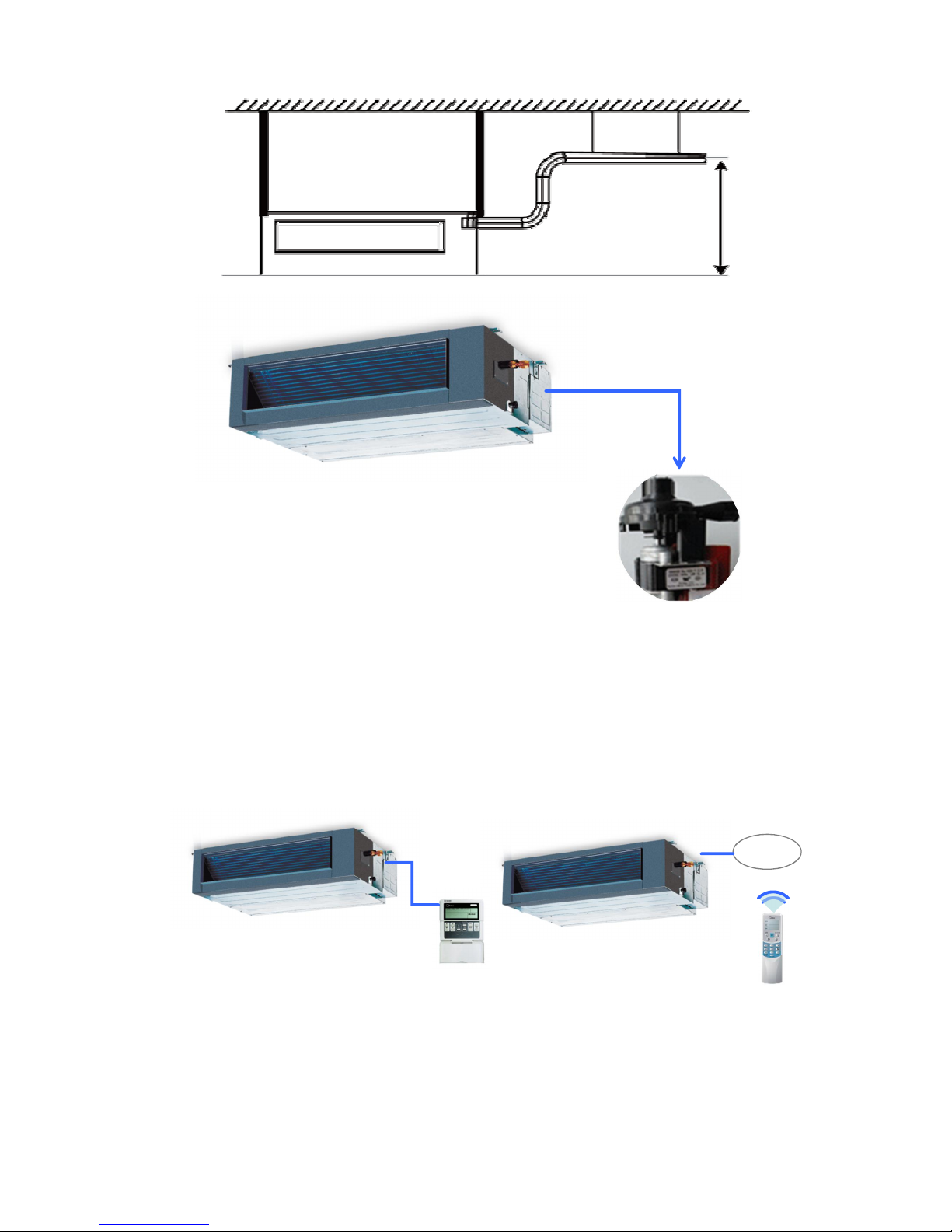
2.3.1.7 Built-in Display Board
The standard indoor unit can be controlled by wired controller.
There is a display board with a receiver in the E-box. Move out the display, and fix it in other place,
even in the distance of 2m(6.56ft). The unit will realized remoter control.
The wired controller and the display board can display the error code or production code when the
chips detect some failure.
Display
750mm(29.53in) upmost
Wired Controller (Standard)
Remote Controller (Optional)
Page 14
12
2.3.2 Cassette Unit
2.3.2.1 Lower Noise
Optimize air channel system design to ensure the maximum quietness and comfort.
Noise max down 6dB.
2.3.2.2 Turbo Mode (Optional)
Turbo function can boost cooling or heating speed in a short period, and makes the room cool
down or heat up rapidly.
2.3.2.3 Fire-proof Controller Box
Electrical control box adopts new design, which can meet higher fire safety requirements.
2.3.2.4 Fresh Air
Fresh air intake function bring you fresh and comfortable air feeling.
2.3.2.5 Wired Controller (Optional)
Compared with infrared remote controller, wired controller can be fixed on the wall and avoid
mislaying. It's mainly used for commercial zone and makes air conditioner control more
convenient.
Old
New
Turbo Mode (After 30 min)
Cold
Hot
Common vs. Turbo
Old
New
Page 15
13
2.3.2.6 Build-in Drain Pump
The drain pump can lift the condensing water up to 750mm(29.53in) upmost.
It’s convenient to install drainage piping under most space condition.
2.3.2.7Terminals For Alarm Lamp and Long-distance On-off Controller Connection Are
Standard
Reserve terminals for the connection of alarm lamp and long-distance on-off controller, more
human control.
Page 16
14
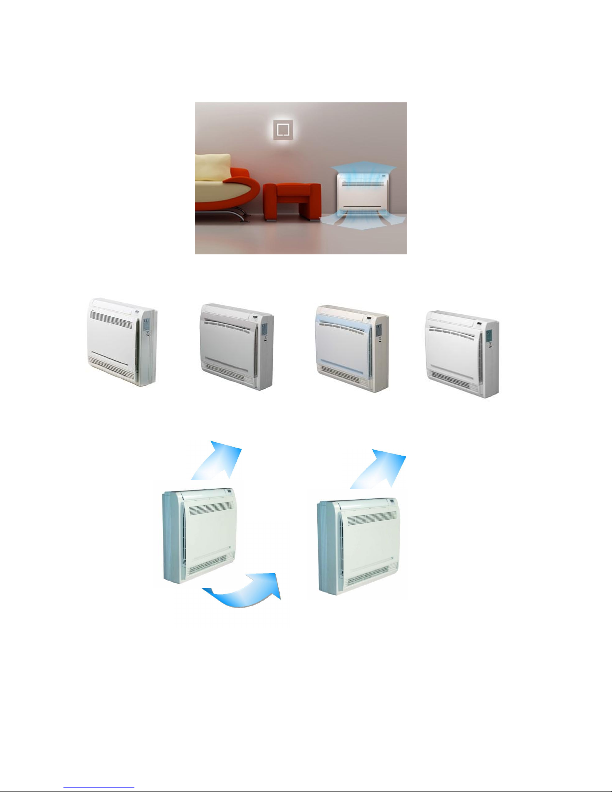
2.3.3 Console
2.3.3.1. Modern and Elegant Appearance
The simple and stylish designs can nicely harmonies with your living space.
3.2.3.2. Four Panels optional
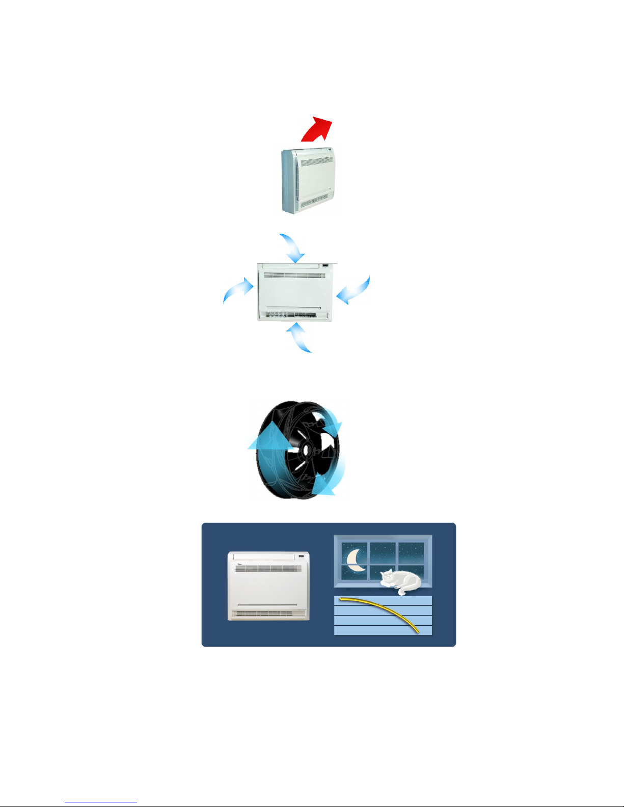
2.3.3.3. Two Air-outlet Ways
Cooling mode
Quick Cooling To maintain room temp
Air outlet from top and bottom to make quick cooling ------When the A/C is just switched on, or
room temp. is still high, cold air will be blown out from top and bottom air outlet to cool down the
room quickly
Air outlet from top to maintain room temp. ----When the room has been cooled down, or the A/C
has been opened over 1 hour, cold air only from the top outlet to keep constant room temp
Page 17
15
Heating mode
Anti-cold air ------When the AC is just turn on, temperature of evaporator is very low, in this case,
in order to prevent cold air direct blowing, only the upper louver is opened in a high position, the
lower louver closed.
2.3.3.4. Four Air Inlets
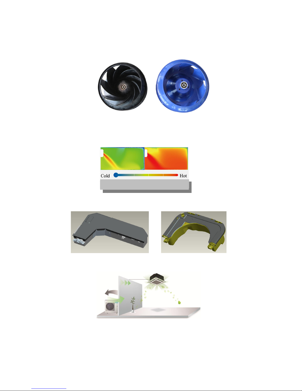
2.3.3.5. Low Noise
DC indoor fan motor, which has five speeds.
Low noise and energy saving.
Advanced centrifugal fan technology makes a fast airflow and reduces the indoor noise.
2.3.3.6. Golden fin is optional.
2.3.3.7. Active carbon filter is standard
Page 18
16
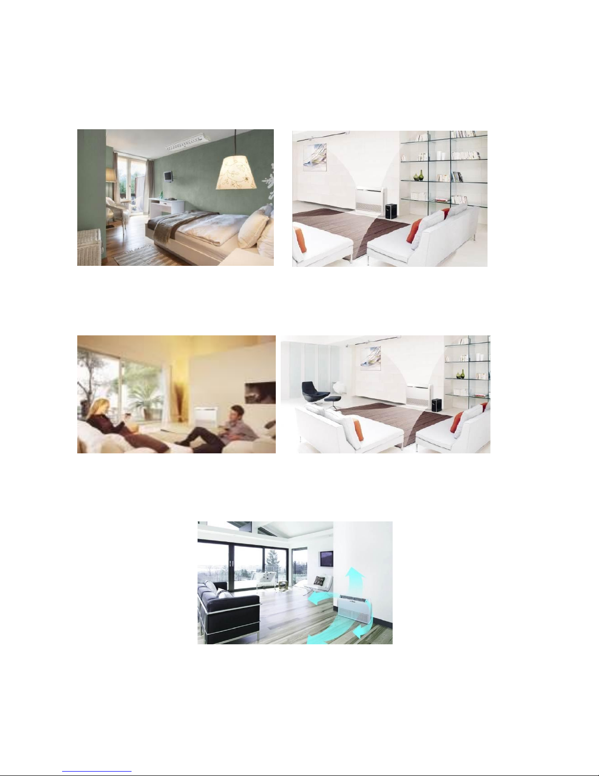
2.3.1 Ceiling-floor Units
2.3.1.1 Two-way Installation
The rounded design of the ceiling and floor type air conditioner allows either ceiling or floor-level
installation. Ceiling installation saves room space, while floor installation helps prevent the loss of
warm air.
2.3.1.2 Brief Design
Brief design that is suitable for any interior will not only give you cooling and heating performance
but also upgrade your lifestyle.
2.3.1.3 3D Airflow
Vertical air flow and horizontal airflow can be adjusted by remote controller, the cooperation of the two
airflow ways help to spread air comfortably throughout even a large room. With these functions, the
whole room can be evenly air-conditioned for both floor-level and ceiling installation.
Page 19
17
2.3.1.4 Optional Drainage Pipe Connection
Both right side and left side drainage holes are available to avoid the space limitation for drainage
pipe installation. Make you more convenient during installation.
C Panel (LED display) D Panel
2.3.1.5 Convenience Operating and Easy Maintenance
Remote controller as standard, wired controller for optional.
The filter without screw fixed, can be took out easily.
2.3.1.6 Easy Installation, Save Working Time
The pipes can be connected from bottom, back and right side, makes the installation more easily.
The wiring works can be finished before installation.
2.3.1.7 Outside Water Pump for Ceiling Installation Only. Floor Mount will require an
External Pump or Gravity Drain
Page 20
18
3. Dimension
3.1 Indoor Unit
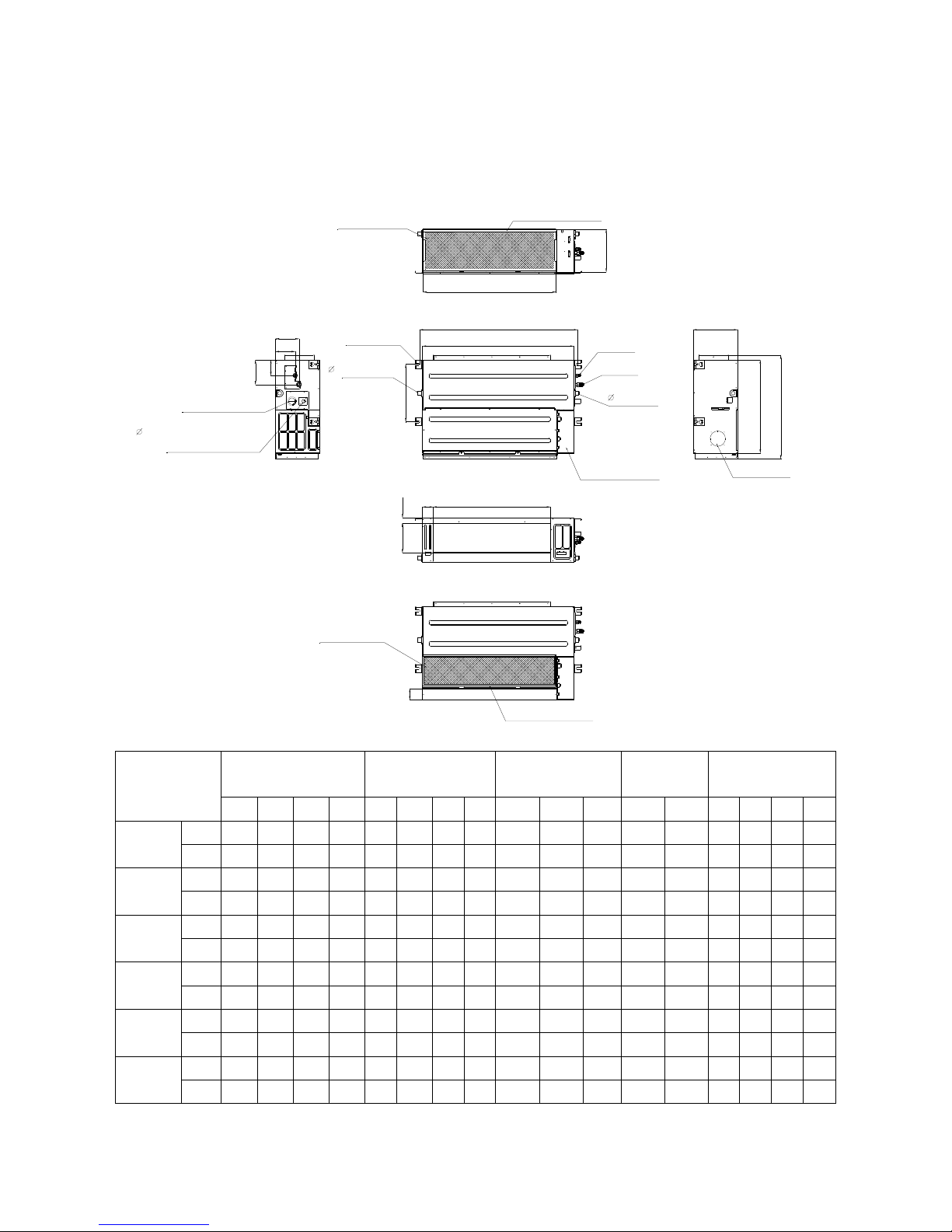
Duct Units
A
C
B
D
J
I
K
Air filter ( optional )
air inlet from rear side
air inlet from bottom side
FE
GH
Electric control box
Air filter ( optional )
L
4-install hanger
Gas side
Liquid side
M
W1
W2
H1
H2
25 Drain connecting pipe
( for pump )
Test mouth & Test cover
Fresh air intake
25 Drain pipe
25 Drain pipe
Capacity (KBtu)
Outline dimension(mm) Air outlet opening size Air return opening size
Size of install
hanger
Size of refrigerant pipe
A B C D E F G H
I J K L M H1 H2 W1 W2
9
mm
700 210 635 570 65 493 35 119 595 200 80 740 350 120 143 95 150
in
27.56 8.27 25 22.44 2.56 19.41 1.38 4.69 23.43 7.87 3.15 29.13 13.78 4.72 5.63 3.74 5.91
12
mm
700 210 635 570 65 493 35 119 595 200 80 740 350 120 143 95 150
in
27.56 8.27 25 22.44 2.56 19.41 1.38 4.69 23.43 7.87 3.15 29.13 13.78 4.72 5.63 3.74 5.91
18
mm
920 210 635 570 65 713 35 119 815 200 80 960 350 120 143 95 150
in
36.22 8.27 25.00 22.44 2.56 28.07 1.38 4.69 32.09 7.87 3.15 37.80 13.78 4.72 5.63 3.74 5.91
24
mm
920 270 635 570 65 713 35 179 815 260 20 960 350 120 143 95 150
in
36.22 10.63 25.00 22.44 2.56 28.07 1.38 7.05 32.09 10.24 0.78 37.80 13 .78 4.72 5.63 3.74 5.91
36
mm
1140 270 775 710 65 933 35 179 1035 260 20 1180 490 120 143 95 150
in
44.88 10.63 30.51 27.95 2.56 36.73 1.38 7.05 40.75 10.24 0.78 46.46 19 .29 4.72 5.63 3.74 5.91
48
mm
1200 300 865 800 80 968 40 204 1094 288 45 1240 500 175 198 155 210
in
47.24 11.81 34.06 31.50 3.15 38.11 1.57 8.03 43.07 11.34 1.77 48.82 19 .69 6.89 7.80 6.10 8.27
1 in
Page 21
19
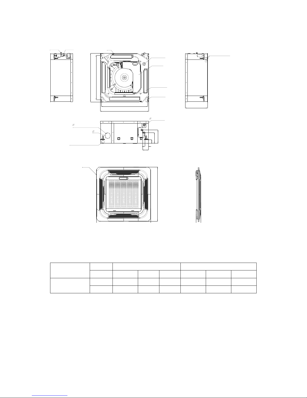
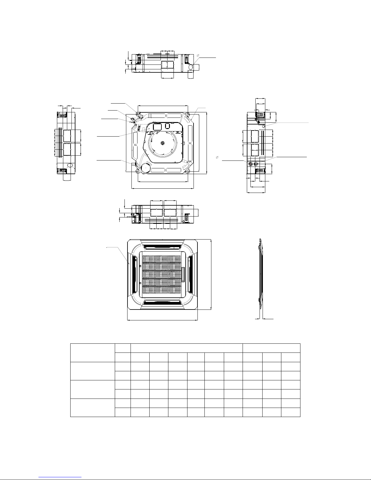
Cassette Units(9K, 12K, 18K)
Panel
Gas side
Liquid side
4-install hanger
Body
Drain pipe32
Fresh air intake
65
647
Drain hole
( for Service )
545
570
260
68
42
157
126
44
Wiring connection port
75
E-parts box
4-Screw hole
(for install panel)
523
570
Wiring connection port
Capacity (Btu/h)
Body Panel
W D H W1 D1 H1
9K/12K/18K
mm 570 260 570 647 50 647
inch 22.44 10.24 22.44 25.47 1.97 25.47
22.44in
(21.46in)
10.24in
25.47in
(20.59in)
1-1/4in
2.95in
2.56in
Page 22
20
Cassette Units (24K, 36K, 48K)
840
840
950
950
C
Test mouth &
Test cover
Drain hole
32
Wiring connection port
680
780
780
680
136
126
91
196
132
A
A
B
A
A
B
AA
B
A
B
Service hole for
draining pump
Fresh air intake
75
55
80
80
4-install hanger
Gas side
Liquid side
E-parts box
135
90
Panel
Body
92929292
D
D
92 92
D
D
D
D
92
9292
92
92 92 92
92
D
D
Capacity
(Btu/h)
Body Panel
W C H A B D W1 D1 H1
24K
mm 840 205 840 160 75 50 950 55 950
inch 33.07 8.07 33.07 6.30 2.95 1.97 37.40 2.17 37.40
36K
mm 840 245 840 160 95 60 950 55 950
inch 33.07 9.65 33.07 6.30 3.74 2.36 37.40 2.17 37.40
48K
mm 840 287 840 160 95 60 950 55 950
inch 33.07 11.30 33.07 6.30 3.74 2.36 37.40 2.17 37.40
2.95in
3.62in
1-1/4in
3.15in
26.77in
(5.35in)
(4.96in)
(37.40in)
(2.17in)
(3.58in)
(33.07in)
(30.70in)
(7.72in)
(5.20in)
(5.31in)
Page 23
21
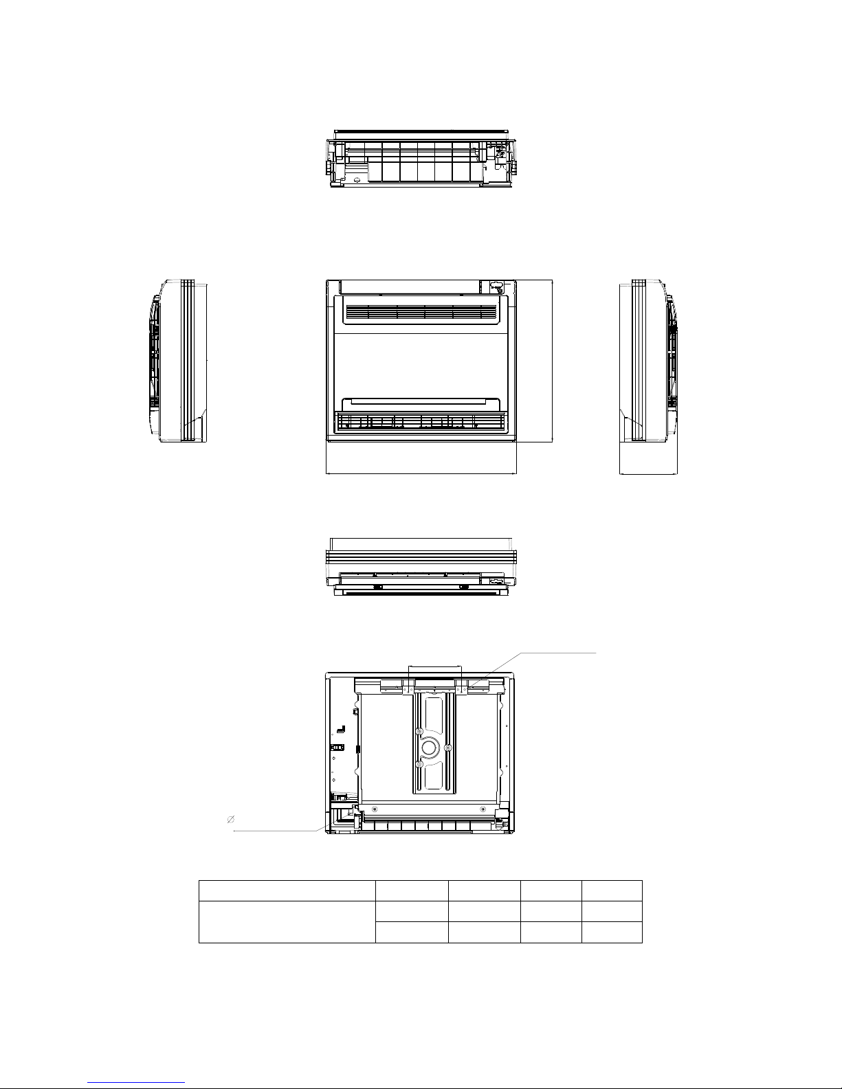
Console Units
16 Drain pipe
195
Hanging arm
Unit: mm
700
600
210
Capacity (Btu/h)
W D H
9K / 12K
mm 700 210 600
inch 27.56 8.27 23.62
(27.56in)
(23.62in)
(8.27in)
(7.68in)
(5/8in)
Page 24
22
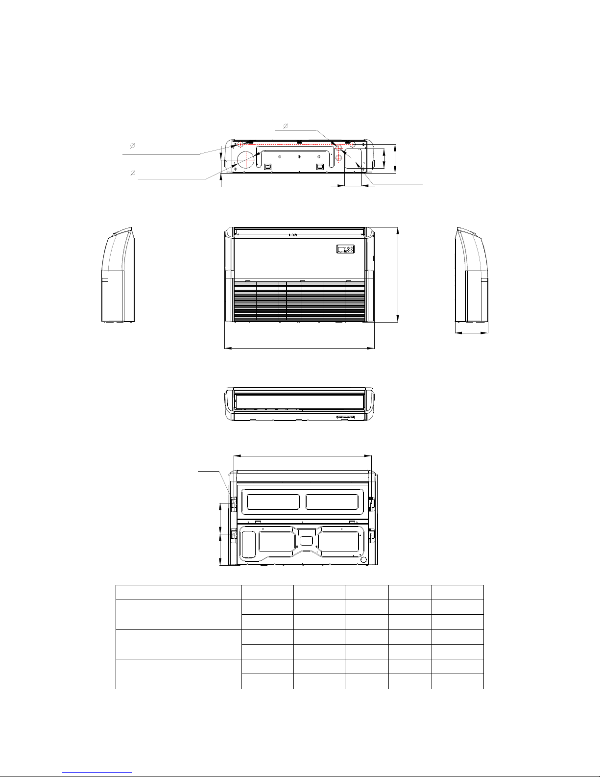
Ceiling-floor Units (18K-48K)
A
B
220
222
C
120
2
-
4
0
120
140
2
-
3
3
Wiring connection port
204
94
Fresh air intake
Drain discharge port
Refrigerant pipe hole
Hanging arm
D
Capacity (Btu/h)
A B C D
18K / 24K
mm 1068 675 235 983
inch 42.05 26.57 9.25 38.70
36K
mm 1285 675 235 1200
inch 50.59 26.57 9.25 47.24
48K
mm 1650 675 235 1565
inch 64.96 26.57 9.25 61.61
(1.30in)
(1.57in)
(4.72in)
(4.72in)
(8.03in)
(5.51in)
(8.66in)
(8.74in)
Page 25
23
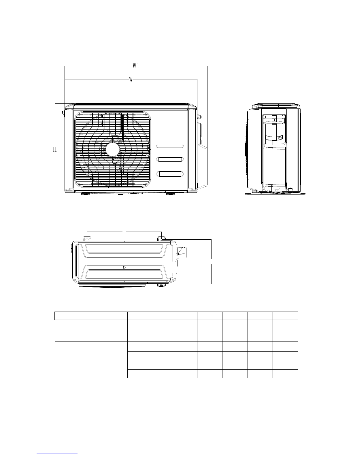
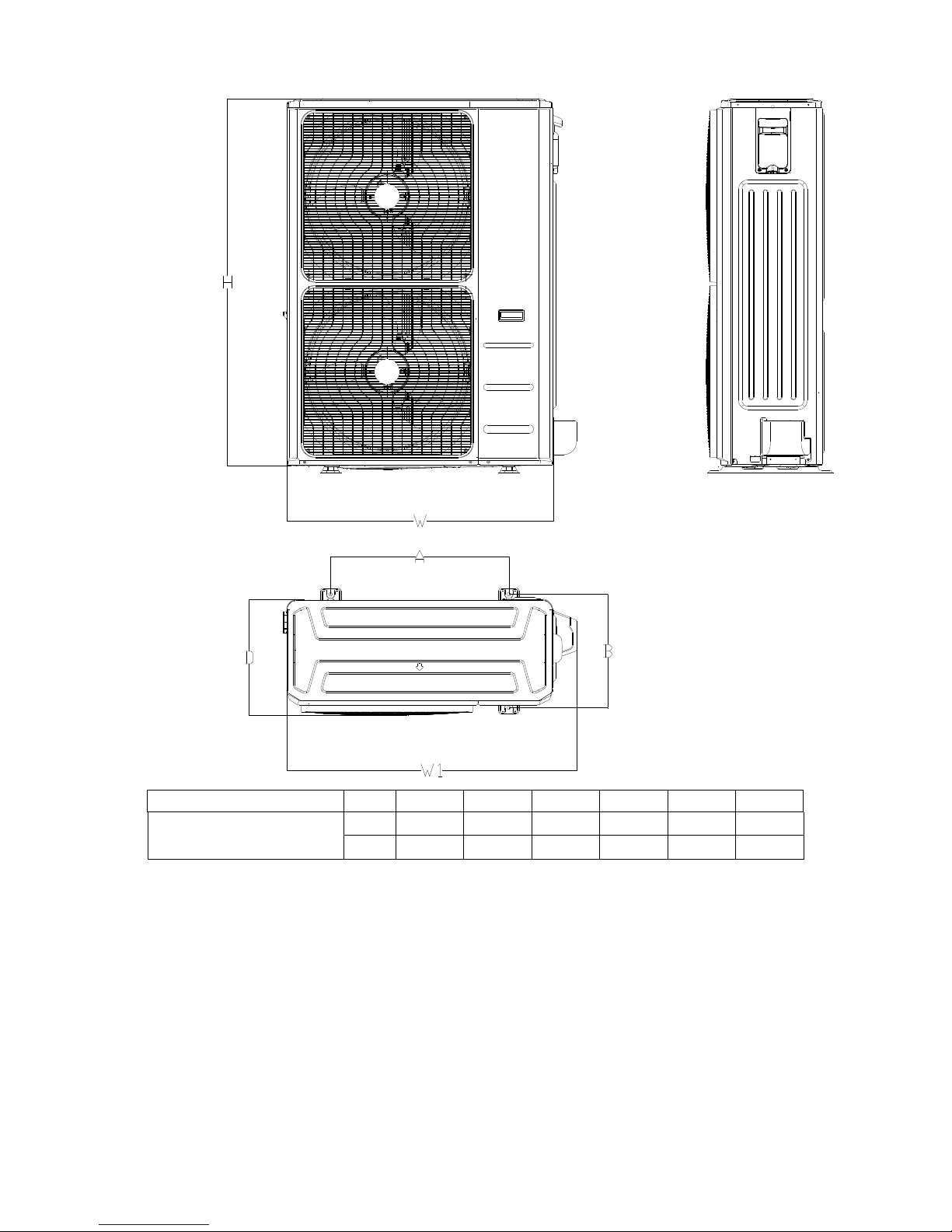
3.2 Outdoor Unit
Note: The above drawing is only for reference. The appearance of your units may be different.
Model W D H W1 A B
MCHSU-09PHH2
MCHSU-12PHH2
mm
800 333 554 870 514 340
inch
31.5 13.1 21.8 34.3 20.2 13.4
MCHSU-18PHH2
mm
845 363 702 914 540 350
inch
33.3 14.3 27.6 36.0 21.3 13.8
MCHSU-24PHH2
MCHS-30PSH2
mm
946 420 810 1030 673 403
inch
37.2 16.5 31.9 40.6 26.5 15.9
A
B
D
Page 26
24
Model W D H W1 A B
MCHSU-48CSH2
mm
952 415 1333 1045 634 404
inch
37.5 16.3 52.5 41.1 25.0 15.9
Page 27

25
4. Service Space
4.1 Indoor Unit
Duct Units
Ensure enough space required for installation and maintenance.
200mm(7.87in) or more
300mm(11.81in) or more
600mmx600mm/23.62inx23.62in
Check orifice
All the indoor units reserve the hole to connect the fresh air pipe. The hole size as following
Cassette Units
Unit: mm/inch
39.3
98.43
11.42
39.3
10.24
6.30in
4.92in
3.15mm
3.54mm
Page 28

26
Console Unit
Ceiling-floor Units
39.37
39.37in
3.94in
39.37in
1.38in
Page 29

27
4.2 Outdoor Unit
More than 30cm
(11.81in)
More than 60cm
(23.62in)
More than 200cm(78.74in)
Air inlet
Air inlet
More than 30cm(11.81in)
Air outlet
(Wall or obstacle)
Maintain channel
More than 60cm
(23.62in)
Page 30
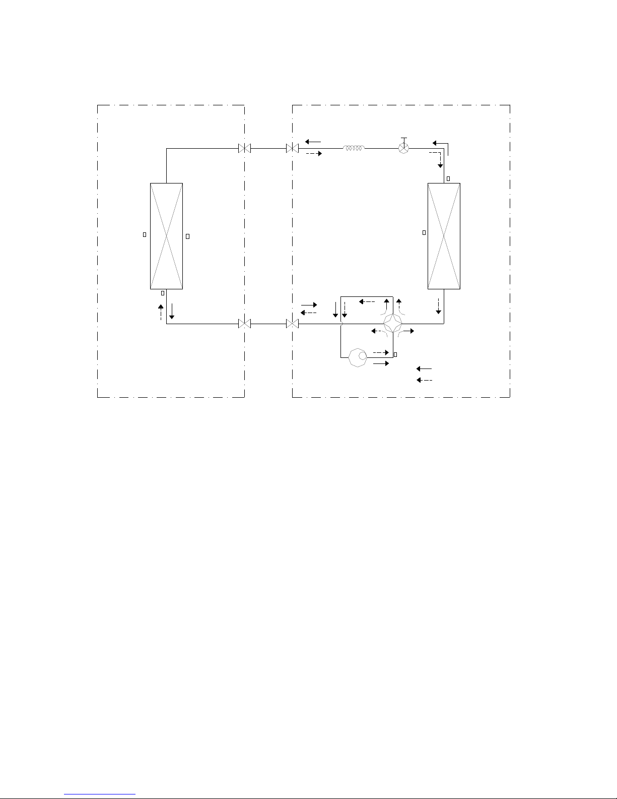
28
5. Refrigerant Cycle Diagram
LIQUID SIDE
GAS SIDE
HEAT
EXCHANGE
(EVAPORATOR)
HEAT
EXCHANGE
(CONDENSER)
Compressor
2-WAY VALVE
3-WAY VALVE
4-WAY VALVE
COOLING
HEATING
T2B Evaporator
temp. sensor
outlet
T1 Room temp.
sensor
T3 Condenser
temp. sensor
T5 Discharge
temp. sensor
T4 Ambient
temp. sensor
INDOOR OUTDOOR
T2 Evaporator
temp. sensor
middle
Electronic
expansion valve
CAPILIARY TUBE
Page 31

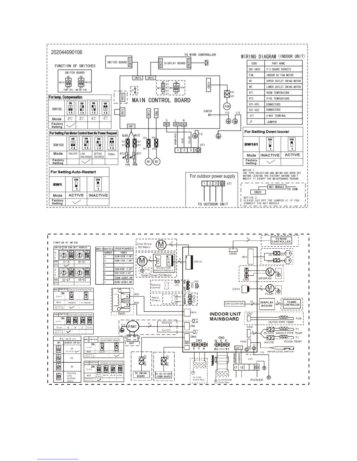
29
6. Wiring Diagram
6.1 Indoor Unit
MEHSU-09CHC2, MEHSU-12CHC2, MEHSU-18CHC2,
MEHSU-24CHC2
MEHSU-09CHD2, MEHSU-12CHD2, MEHSU-18CHD2,MEHSU-24CHD2
Page 32
30
MEHSU-09CHN2, MEHSU-12CHN2
MEHSU-36CSC2, MEHSU-48CSC2
Page 33

31
MEHSU-36CSD2, MEHSU-48CSD2
Page 34

32
MEHSU-18CHF2, MEHSU-24CHF2
MEHSU-36CSF2
Page 35

33
MEHSU-48CSF2
MEHSU-36CSF2,MEHSU-48CSF2
Page 36

34
6.2 Outdoor Unit
MCHSU-09PHH2 ,MCHSU-12PHH2 , MCHSU-18PHH2
Page 37

35
MCHSU-24PHH2
Page 38

36
MCHSU-36CSH2
Page 39

37
MCHSU-48CSH2
PCB board of
MCHSU-09PHH2, MCHSU-12PHH2, MCHSU-18PHH2
Suction
Exhaust
+
17122200000309
HuiQi
TestPort
1
1
HEAT
4-WAY
W
BLUE
BLACK
RED
V
U
TPT3T4
No
NO
NO
YES
Low-Fre
No
Have
YES
Have
Temp-Pro
Rdi
Ripm
11
PMV
44
15V17V
[V1.8] 2015-01-16
7815
22
1
34
REACTOR
311 TEST
7805
N-IN
DC-FAN
AC-FAN
L-IN
S
KFR-72W/BP2-(311+0515+6061HD+PSS30S92F6-AG+6822+HEAT).D.13.WP2.1
12V 5V
CN3
DSA1
K
A
K
D5
R18
R46
R
1
0
7
A
R515A
R316A
R18A
IC403
D4
C21
R54
R55
R68
R69
R56
R90
C14
J4
R16
R52
J5
+
LED1
R78
R142
R141
R155
R154
R153
R152
R151
R150
C3
R108
R107
RC2
RC4
RC1
RC3
C1
FUSE1
65T 250V30A
ZR1
ZR2
CN30
R109
R58
R61
R60
R59
C301
C76
C312
R315
C83
C85
C86
C91
R156R158
R169
R170
R171
R172
IC34
D11
R157
R159
C310
C306
C308
C311
C307
C309
R110
E305
C302
+
DZ301
Q3
R75
R84
C103
CN28
CN29
CN6-1
CN6
CN13
CN12
CN2
CN8
CN7
CN22
DR
CN21
DR
R102
J6
PTC1
CN414
R127
C105
+
E5
IPM2
C501
C503
C507
C508
C509
C510
C511
C512
C517
+
DZ501
R501
R502
R503
R504
R505
R506
R509
R510
R511
R512
R513
R514
R523
C502
C505
+
DZ502
R515
R522
+
DZ504
C504
R316
~ ~
IN
AC
-
+
R101
R100
R71
C42
CN20
RY5
CN16
CN18
NTC4
C8
C513
C514
C515
C516
R516
R517
R518
R519
R520
R521
C27
IC7
24LC512
33
49
17
1
IC9
R53
IC101
R160
+
E4
+
E3
R83
R82R81
R80
R79
R50
C47
C20
R322
R321
R320
Q2
IC405
+
E10
R120
R167
R166
R32
+
E1
R12
+
LED3
R412
R413
R414
R415
Rdi
Ripm
R13
CN24
R72
R8
R87
R74
J3
IC17
+
E24
D2
R124
C2
J2
J1
C77
AC AC
+
-
BR1
C13
D3
R7
RY3
RY4
RY2
CN5
R23
R24
R25
R26
R27
C74
C75
RY1
+
E14
C9
C17
C18
C19
C23
C24
C26
C32
C33
C35
C36
C37
C39
C43
C48
C49
C52
C65C67
C78
C87
C89
C90
C92
C147
C153
C25
CN9
CN23
CN39
+
E17
+
E23
+
E28
IC8
24LC08
IC12
24LC08
IC14
+
LED2
OSC1
R5
R30
R31
R40
R41
R42
R48
R49
R62
R64
R65 R66
R70
R73
R76
R77
R86
R92
R97
R161
R162
R163
R164
R165
R176
R177
R419
X1
C58
+
+
E405
IC404
R45
Q1
C15
C22
R21
R22
R28
R29
R33
+
E22
R3
R4
R121
C5
+
E6
R10
C28
C4
CN38
IC10
C79
C80
D7
C6
R148
R63
C506
R507
R508
+
E11
R106
C73
IC21
PC817
IC31
PC817
R175
R178
C409
IC402
C403
IC11
+
E402
D401
C401
R403
C411
C40
C50
D403
R401
R405
R406
R404
+
E404
D402
D404
C408
C402
+
E403
R407
R408
C404
C110
+
E409
+
E401
R402
C405
10
9
7
6
5
4
3
1
T401
C406
C407
D13
D14
+
E406
+
E407
+
E408
+
E502
+
E503
+
E504
+
DZ503
CN25
R6
R9
CN60
IC406
IC407
C7
D1
R1
R137
IC2
PC851
IC1
PC817
R2
R126
R125
R123
R122
R119
R118
R117
R15
R14
C99
C98
C97
C96
C95
C94
C93
C66
D20
R17
CN17
CN10
CN1
C41
R38
C45
C44
R136
R135
R134
R104
D12
D10
C54
+
D8
D9
R57
R20
C242
C243C244
R89
E2
R67
C84
C10
C11
IC4
C12
C38
R34
R47
R88
IC32
R39
R35
R36
R19
+
DZ6
R37
C46
C51
C53
CN19
+
DZ2
+
E27
IC3
PC817
IC5
PC817
Q8
R43
R44
R85
R91
R93
R95
R96
R99
D15
R51
+
E410
+
E8
C60
C61
E302
E303
E304
C62
VN1
VP1
U
P
VUB
U+
W
V+
V
W+
U-
VVB
VWB
FO
WV-
NV
NW
NU
VNC
CIN
IPM1
+
DZ304
+
DZ303
+
DZ302
C314
C316
C318
C30
C34
C31
ZR3
ZR4
C82
L1
R11
R140
CN27
E301
R168
IGBT1
connect to the DR module
connect to earth
fuse 250V 30A
connect to reactance
290-330VDC standby
210-300VDC running
power supply 208-230V AC connect to the terminal
connect to 4-way valve
when 4-way is on, output 208-230V AC
AC FAN mototr
connect to compressor heater
when heater is on, output 208-230V AC
1 low speed
2 hign speed
3 ground
external drive motor
connect to DC motor
0V AC standby
10~200V AC’ running
U
V
W
connect to electric expansion valve
6 5 4 3 2 1
+12VDC
+12VDC
+12V DC pulse wave between( +4)-GND
+12V DC pulse wave between( +3)-GND
+12V DC pulse wave between( +2)-GND
+12V DC pulse wave between( +1)-GND
EEPROM Programmer Port
reserve
test port
Connect to PC
communication
V
U
W
connect to PC communication
test port
LED2 (red)&LED3(green): status light
combination LED2 and LED3 show errors
(
refer to the attechment Word
)
LED: status light(yellow
)
slow flicker:standby(0.5Hz
)
quick flicker:error (2Hz
)
continuous light: running
internal drive motor
6 5 4 3 1
rotate speed feedback signal
0-15V square signal
drive power voltage: +15VDC
DC negative pole: GND
DC positive pole P: 315VDC
exhaust temp. sensor
pipe temp.sensor& room temp. sensor
TP T4 T3
7 6 5 4 3 2 1
RT
+5V DC
RT
RT
+5V DC
+5V DC
CN5/CN4 connect to chassis heater
when heater is on, output 208-230V AC
connect to DC motor
0V AC standby
10~200V AC’ running
bridge
IGBT
fast recovery diode
(FRD)
IPM for compressor
IPM for DC FAN
reserve
P
N
Page 40

38
For MCHSU-24PHH2, MCHSU-36CSH2,
N
L
SHOW/SW
EARTH
[1.4]2014.06.26
EU-KFR105W/BP3T5N1-350S.D.13.WP1-1
L-OUT
N-OUT
CONNECT TO INVERTER driver
HIGH
LOW
T2B-E T2B-DT2B-C
T2B-B
T2B-A
TP
T4
T3
S-E
S-D
S-C
S-B
S-A
FAN_OUT
FAN_IN
Q
E
P
AB
C
D
E
202302141206
CN19
D4
R134
R133
R89
R37
+
E12
+
E15
CN10
N
C18
CN9
ZR3
ZR2
ZR1
X1
S
RY8
RY7
RY6
RY5
RY3
RY2
R213
R212
R211
R210
R180
R170
R140
R131
R130
R129
R128
R127
R126
R125
R124
R123
R121
R120
R118
R117
R116
R115
R114
R113
R112
R111
R110
R109
R108
R107
R106
R105
R104
R103
R102
R101
R100
R99
R98
R96
R95
R94
R93
R92
R91
R90
R88
R81
R80
R79
R78
R77
R76
R75
R74
R73
R72
R71
R70
R69
R68
R67
R66
R65
R64
R63
R62
R61
R60
R59
R58
R57
R56
R55
R54 R53
R52
R51
R50
R49
R48
R47
R46
R45
R44
R43
R42
R41
R40
R39
R38
R36
R35
R34
R33
R32
R31
R30
R29
R28
R27
R26
R25
R24
R23
R22
R21
R20
R19
R18
R17
R16
R15
R14
R13
R12
R11
R10
R9
R8
R7
R6
R5
R4
R3
R2
R1
Q5
Q2
PTC1
LED1
L3
IC30
IC22
IC21
IC20
IC19
IC18
IC17
IC16
IC15
IC14
IC13
IC12
IC10
IC9
IC8
IC7
IC6
IC5
IC2
IC1
FUSE2
5A/250V
FUSE1
T30A/250V
E21
E20
+
E19
+
E16+E14
E13
E11
E9
E8
E5
E4
E3
E1
DSP1
DSA1
D28
D27
D26
D25
D24
D23
D22
D21
D20
D19
D18
D17
D16
D15
D14
D13
D12
D11
D10
D9
D8
D7
D6
D5
D3
D2
D1
CONdebug
CN44
HEAT2
CN43
FAN
CN42
C
CN41
C
CN40
HEAT1
CN34
CN33
CN30
CN29
CN28
CN27
CN26
CN22
4-WAY
CN20
CN18
CN17
CN16
CN14
CompTop
CN12
CN11
CN8
CN6
CN5
CN4
N
CN3
N
CN2
N-IN
CN1
L-IN
C103
C98
C97
C96
C95
C94
C93
C92
C91
C90
C72
C70
C69
C68
C67
C66
C65
C64
C62
C61
C60
C59
C58
C57
C56
C55
C54
C53
C52
C51
C50
C49
C48
C47
C46
C45
C44
C43
C42
C41
C40
C39
C38
C37
C36
C35
C34
C33
C32
C31
C30
C29
C28
C27
C26
C25
C24
C23
C22
C21
C20
C19
C17
C16
C15
C14
C13
C12
C11
C10
C9
C8
C7
C6
C5
C4
C3
C2
C1
JP1
JP2
D29
D30
CN23
~ ~
-++-
SSR1
CN7
CN13
P-1
L1
R82
R83
R84
R85
R86
R87
R97
R119
R122
R132
CN35
N
CN37
FAN-L
Q3
Q6
Q7
Q8
Q9
CN36
FAN-H
E2
IC3
Q1
Q4
IC4
ZR4
RY4
CN32
CN38
L2
R135
SW1
CN21
Electric Expansion
Value B
Electric Expansion
Value E
Electric Expansion
Value D
Electric Expansion
Value C
Electric Expansion
Value A
485
communication
testPort
connect to detector
external drive DC fan
motor input terminal
external drive DC fan
motor ouput terminal
current loop
communication A
current loop
communication B
current loop
communication C
current loop
communication D
current loop
communication E
digital display
Fuse
T30A/250V
connect to high and low
pressure sensor
connect to
trmp. sensor
Fuse 5A/250V
connect to earth
CN23 reserve
digital display button
test report
connect to detector
CN43-5,CN43-1/CN41,CN42
AC fan motor capacitor
connector
CN43-4/CN37 CONNECT TO
AC FAN MOTOR(LOW SPEED)
CN43-3/CN36
AC fan motor low speed
connector
CN43-2/CN35
AV fan motor N phase
current loop
communication C
Signal wire
24VDC Pulse wave
connect to the terminal
connect to the terminal
208-230V AC
power supply
room temp sensor
pipe temp sensor
(3.3V)
(3.3V)
high pressure sensor
low pressure sensor
Connect to the Indoor evap.pipe
out temp. sensor
T2B-A、T2B-B、T2B-C、T2B-D、T2B-E
+12V DC pulse wave between (+1)-GND
+12V DC pulse wave between (+2)-GND
+12V DC pulse wave between (+3)-GND
+12V DC pulse wave between (+4)-GND
+12V DC
+12V DC
6 5 4 3 2 1
when 4-way is ON, output 208-230VAC
connect to the 4-WAY
when heater is ON, output 208-230V AC
connect to compressor heater
CN44 L
CN10 N
CN40 L
CN4 N
CN22 L
CN3 N
connect to exhaust
temp. sensor
connect to the terminal
208-230V AC
external drive DC fan
motor connector
T3
T4
electric
heater1
electric
heater 2
Page 41

39
For MCHSU-48CSH2
Page 42

40
IPM board of MCHSU-24PHH2,
MCHSU-36CSH2,
202302141237
PFC-L2
[1.6]2014.10.16
EU-KFR105W/BP2T3N1-350(767).D.13.MP2-1
PFC-L1
CN58
EARTH
C57
C56
6
J146J15
R65
C55
C53
E31
C50
D7
C49
+
E30
C47
C9
ZR1
DZ3
R8
E3
E2
CN55
TO-MAIN
E23
C46
R13
IC3
C113
W
V
U
1
6
7
10
11
12
1314
15
3 8
T1
R208
R207
R206
R205
R204
R203
R202
R198
R197
R196
R194
R192
R187
R186
R185
R184
R183
R182
R181
R180
R179
R175
R174
R173
R170
R163
R160
R150
R147
R146
R144
R143
R141
R140
R139
R137
R135
R133
R132
R131
R130
R129
R128
R127
R126
R125
R124
R119
R114
R111
R107
R104
R96
R92
R91
R90
R82
R80
R79
R78
R77
R76
R75
R66
R63
R62
R61
R60
R59
R58
R57
R56
R55
R54
R53
R52
R51
R50
R49
R48
R47
R46
R45
R44
R43
R42
R41
R40
R39
R38
R37
R36
R35
R33
R32
R31
R30
R29
R27
R26
R25
R24
R23
R22
R21
R20
R19
R18
R17
R15
R14
R12
R11
R10
R9
R7
R5
R2
R1
Q2
OSC1
+
LED4+LED3
JR1
J201
6
J1
IPM2
1
IPM1
1
17
49
33
IC20
IC17
IC16
IC15
24C256
IC14
24C08
IC10
IC7
IC4
IC2
E34
E33
E27
E25
+
E24
+
E22
+
E21
+
E20
+
E17
E16
E15
E14
E13
E12
E10
E9
+
E8
+
E7
+
E6
+
E5
E4
E1
+
DZ9
+
DZ8
+
DZ7
+
DZ6
+
DZ1
D26
D14
D13
D12
D11
D10
D9
D8
D6
D5
D4
D3
D2
CN57
1
CN56
CN54
L-IN2
CN53
N-IN2
CN52
CN51
CN19
OUTFAN(DC)
C124
C123
C122
C121
C120
C119
C118
C117
C116
C114
C111
C109
C108
C107
C106
C105
C104
C103
C102
C101
C100
C99
C97
C94
C82
C79
C78
C77
C76
C72
C71
C70
C69
C67
C66
C65
C64
C61
C60
C59
C54
C51
C40
C39
C38
C36
C33
C32
C31
C30
C29
C26
C25
C24
C23
C22
C21
C20
C19
C18
C17
C16
C15
C14
C13
C12
C11
C8
C7
C6
C5
C4
C3
C2
C1
BR1
R3
R4
R6
R16
C27
C28
+
E18
C10
+
E19
C34
+
D1
+
D15
+
D16
22
44
23
IC1
C52
D17
R28
6J36
J4
6
J2
6
J5
6
J6
6
J7
6
J8
6J96
J10
6
J11
6
J12
6
J13
C35
C37
C41
C42
C43
C44
C45
E26
E28
E29
IC11
IC12
R34
R64
C48
E11
CN53
power supply
connect to the terminal
208-230V AC
CN54
CN51
CN52
PFC
inductance
terminal
CN58
EATTH
+
210-300VDC (Running)
CAPACITOR Voltage
290-330VDC (standby)
CN55
TO MAIN
CN19
connect to DC fan motor
U
V
W
10-200VAC (running)
0VAC (standby)
connect to the compressor
U
V
W
10-200VAC (running)
0VAC (standby)
CN57
Debug
For MCHSU-48CSH2
Page 43

41
7. Fan Curves
ENC2
Static Pressure
Range In. WG (Pa)
Model
(K Btu/h)
Model 0 1 2 3 4
Model≤12
0.02
(5)
0.04
(10)
0.08
(20)
0.12
(30)
0.16
(40)
0-0.18
(0-45)
Model=18
0.04
(10)
0.10
(25)
0.14
(35)
0.18
(45)
0.22
(55)
0-0.28
(0-70)
18<Model≤24
0.04
(10)
0.10
(25)
0.16
(40)
0.22
(55)
0.28
(70)
0-0.40
(0-100)
24<Model≤60
0.08
(20)
0.14
(35)
0.20
(50)
0.26
(65)
0.32
(80)
0-0.40
(0-100)
Factory Setting √
Page 44
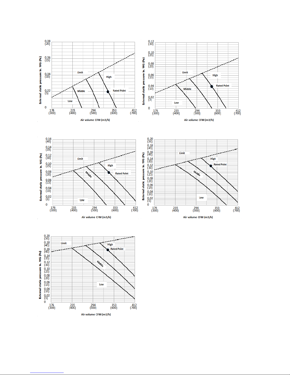
42
MEHSU-09CHD2,
Code 0 Code 1
Code 2 Code 3
Code 4
Page 45

43
MEHSU-12CHD2
Code 0 Code 1
Code 2 Code 3
Code 4
Page 46

44
MEHSU-18CHD2
Code 0 Code 1
Code 2 Code 3
Code 4
Page 47

45
MEHSU-24CHD2
Code 0 Code 1
Code 2 Code 3
Code 4
Page 48

46
MEHSU-36CSD2
Code 0 Code 1
Code 2 Code 3
Code 4
Page 49

47
MEHSU-48CSD2
Code 0 Code 1
Code 2 Code 3
Code 4
Page 50

48
8 Electric Characteristics
Model
Indoor Unit
Hz Voltage Min. Max.
MEHSU-09CHC2 60 208-230V 187V
253V
MEHSU-09CHD2 60 208-230V 187V
253V
MEHSU-09CHN2 60 208-230V 187V
253V
MEHSU-12CHC2 60 208-230V 187V
253V
MEHSU-12CHD2 60 208-230V 187V
253V
MEHSU-12CHN2 60 208-230V 187V
253V
MEHSU-18CHC2 60 208-230V 187V
253V
MEHSU-18CHD2 60 208-230V 187V
253V
MEHSU-18CHF2 60 208-230V 187V
253V
MCHSU-36CSH2 60 208-230V 187V
253V
MEHSU-24CHD2 60 208-230V 187V
253V
MEHSU-24CHF2 60 208-230V 187V
253V
MEHSU-36CSC2 60 208-230V 187V
253V
MEHSU-36CSD2 60 208-230V 187V
253V
MEHSU-36CSF2 60 208-230V 187V
253V
MEHSU-48CSC2 60 208-230V 187V
253V
MEHSU-48CSD2 60 208-230V 187V
253V
MEHSU-48CSF2 60 208-230V 187V
253V
Page 51

49
9 Sound Level
9.1 Indoor unit
Suction
Discharge
Microphone
1.4m
Concealed Duct Type
DuctDuct
Model
Noise level dB(A)
H M L
MEHSU-09CHD2
37 34 31
MEHSU-12CHD2
39 36 32
MEHSU-18CHD2
35 33 31
MEHSU-24CHD2
50 47 45
MEHSU-36CSD2
53 49 45
MEHSU-48CSD2
44 47 41
(4.59ft)
Page 52

50
1.4m
Micro phone
Model
Noise level dB(A)
H M L
MEHSU-09CHC2
41 39 37
MEHSU-12CHC2
41 38 35
MEHSU-18CHC2
46 43 41
MEHSU-24CHC2
51 47 43
MEHSU-36CSC2
52 47 44
MEHSU-48CSC2
53 49 45
(4.59ft)
Page 53

51
1.5m
1m
Microphone
Model
Noise level dB(A)
H M L
MEHSU-09CHN2 45 41 35
MEHSU-12CHN2 44 42 38
Microphone
1m
1m
Air outlet side
1.5m
1m
Microphone
Model
Noise level dB(A)
H M L
MEHSU-18CHF2
47 44 38
MEHSU-24CHF2
53 49 45
MEHSU-36CSF2
55 48 41
MEHSU-48CSF2
57 54 52
(4.92ft)
(3.28ft)
(3.28ft)
(3.28ft)
(4.92ft)
(3.28ft)
Page 54

52
9.2 Outdoor unit
Note: H= 0.5 × height of outdoor unit
Model Noise Level dB(A)
MCHSU-09PHH2 59
MCHSU-12PHH2 56
MCHSU-18PHH2 59
MCHSU-24PHH2 61
MCHSU-36CSH2
65
MCHSU-48CSH2 63
H
1.0m
Outdoor Unit
Microphone
(3.28ft)
Page 55

53
10 Accessories
Duct Units
Name Shape Quantity
Tubing & Fittings
Soundproof / insulation sheath
2
Binding tape
1
Seal sponge
1
Drainpipe Fittings
(for cooling & heating)
Drain joint
1
Seal ring
1
Wired controller & Its Frame
Wired controller
1
Others
Owner,s manual
1
Installation manual
1
EMS & It’s fitting
Magnetic ring (twist the electric wires L
and N around it to five circles)
1
Cassette Units
Name Shape Quantity
Installation Fittings
Installation paper board
1
Tubing & Fittings
Soundproof / insulation sheath
1
Drainpipe Fittings
Out-let pipe sheath
1
Out-let pipe clasp
1
Drain joint
1
Seal ring
1
Remote controller & Its
Frame(The product you
have might not be
Remote controller & Its Frame
1
Page 56

54
provided the following
accessories)
Remote controller holder
1
Mounting screw(ST2.9×10-C-H)
2
Remote controller manual
1
Alkaline dry batteries (AM4)
2
Others
Owner's manual
1
Installation manual
1
Installation accessory
(The product you have
might not be provided the
following accessories
Expansible hook
4
Installation hook
4
Orifice
1
Console Units
Name Shape Quantity
Installation fittings
Hook
2
Remote controller & Its Frame
Remote controller
1
Frame
1
Mounting screw(ST2.9×10-C-H)
2
Alkaline dry batteries (AM4)
2
Others
Installation manual / 1
Owner's manual / 1
Ceiling-floor Units
Remote controller & Its
holder
1. Remote controller
1
2. Remote controller holder
1
3. Mounting screw (ST2.9×10-C-H)
2
4. Alkaline dry batteries (AM4)
2
Others
5. Owner's manual
1
6. Installation manual
1
7. Remote controller manual
1
Page 57
55
11 The Specification of Power
Type
9K-18K
24K
Power
Phase 1-phase 1-phase
Frequency and Voltage 208-230V, 60Hz 208-230V, 60Hz
Circuit Breaker/ Fuse (A) 25/20 40/30
Indoor Unit Power Wiring (mm2)
Indoor/Outdoor
Connecting
Wiring
Ground Wiring 2.5 2.0
Outdoor Unit Power Wiring
3×2.5 3×2.0
Strong Electric Signal 4×1.0 4×1.5
Weak Electric Signal
Model 36K 48K
Power
Phase 1-phase 1-phase
Frequency and Voltage 208-230V, 60Hz 208-230V, 60Hz
Circuit Breaker/ Fuse (A) 60/40 70/55
Indoor Unit Power Wiring (mm2)
Indoor/Outdoor
Connecting
Wiring
Ground Wiring 4.0 4.0
Outdoor Unit Power Wiring
3×4.0 3×4.0
Strong Electric Signal 3×1.5 3×1.5
Weak Electric Signal 3×0.5 3×0.5
Page 58

56
12 Field Wiring
36K, 48K
Page 59

57
12 Installation Details
12.1 Location selection
12.1.1
Indoor unit location selection
The place shall easily support the indoor
unit’s weight.
The place can ensure the indoor unit
installation and inspection.
The place can ensure the indoor unit
horizontally installed.
The place shall allow easy water drainage.
The place shall easily connect with the
outdoor unit.
The place where air circulation in the room
should be good.
There should not be any heat source or
steam near the unit.
There should not be any oil gas near the unit
There should not be any corrosive gas near
the unit
There should not be any salty air neat the
unit
There should not be strong electromagnetic
wave near the unit
There should not be inflammable materials
or gas near the unit
There should not be strong voltage vibration.
12.1.2
Outdoor unit location selection
The place shall easily support the outdoor
unit’s weight.
Locate the outdoor unit as close to indoor
unit as possible
The piping length and height drop cannot
exceed the allowable value.
The place where the noise, vibration and
outlet air do not disturb the neighbors.
There is enough room for installation and
maintenance.
The air outlet and the air inlet are not
impeded, and not face the strong wind.
It is easy to install the connecting pipes and
cables.
There is no danger of fire due to leakage of
inflammable gas.
It should be a dry and well ventilation place
The support should be flat and horizontal
Do not install the outdoor unit in a dirty or
severely polluted place, so as to avoid
blockage of the heat exchanger in the
outdoor unit.
If is built over the unit to prevent direct
sunlight, rain exposure, direct strong wend,
snow and other scraps accumulation, make
sure that heat radiation from the condenser
is not restricted.
More than 30cm/11.81in
More than 60cm/23.62in
More than 200cm/78.74in
More than 30cm/11.81in
More than
60cm/23.62in
(Service space)
F
e
n
c
e
o
r
o
b
s
t
a
c
l
e
s
12.2 Indoor unit installation
12.2.1
A5 duct indoor unit installation
12.2.1.1 Service space for indoor unit
12.2.1.2 Bolt pitch
7.87in
11.81in
23.62inx23.62in
Page 60

58
12.2.1.3 Install the pendant bolt
Select the position of installation hooks
according to the hook holes positions showed
in upper picture.
Drill four holes of Ø12mm(0.47in),
45~50mm(1.57~1.97in) deep at the selected
positions on the ceiling. Then embed the
expansible hooks (fittings).
12.2.1.4 Install the main body
Make the 4 suspender through the 4 hanger of
the main body to suspend it. Adjust the
hexangular nuts on the four installation hooks
evenly, to ensure the balance of the body. Use
a leveling instrument to make sure the
levelness of the main body is within ±1°.
12.2.1.5 Install the air filter
Insert the air filter through the filter slot and fix it
with 2 screws.
12.2.1.6 Install the air duct
Please design the air duct as below
recommended picture
12.2.1.7 Change the air inlet direction
① Take off ventilation panel and flange, cut off
the staples at side rail.
② Stick the attached seal sponge as per the
indicating place in the following fig, and then
change the mounting positions of air return
panel and air return flange .
Capacity(KBtu)
Size of outline dimension mounted
plug
L M
9
mm
740 350
in
29.13 13.78
12
mm
740 350
in
29.13 13.78
18
mm
960 350
in
37.80 13.78
24
mm
960 350
in
37.80 13.78
36
mm
1180 490
in
46.46 19.29
48
mm
1240 500
in
48.82 19.69
Page 61

59
③ When install the filter mesh, please plug it
into flange inclined from air return opening, and
then push up.
④ The installation has finish, upon filter mesh
which fixing blocks have been insert to the
flange positional holes.
12.2.2 Compact cassette indoor unit
installation
12.2.2.1 Service space for indoor unit
12.2.2.2 Bolt pitch
12.2.2.3 Install the pendant bolt
Select the position of installation hooks
according to the hook holes positions showed
in upper picture.
Drill four holes of Ø12mm(0.47in), 45~50mm
(1.57in~1.97in) deep at the selected positions
on the ceiling. Then embed the expansible
hooks (fittings).
Face the concave side of the installation hooks
toward the expansible hooks. Determine the
length of the installation hooks from the height
of ceiling, then cut off the unnecessary part.
39.37in
25.47in
22.44in
21.46in
20.59in
Page 62

60
If the ceiling is extremely high, please
determine the length of the installation hook
depending on the real situation.
12.2.2.4 Install the main body
Make the 4 suspender through the 4 hanger of
the main body to suspend it. Adjust the
hexangular nuts on the four installation hooks
evenly, to ensure the balance of the body. Use
a leveling instrument to make sure the
levelness of the main body is within ±1°.
Adjust the position to ensure the gaps between
the body and the four sides of ceiling are even.
The body's lower part should sink into the
ceiling for 10~12 mm (0.39-0.47in). In general,
L is half of the screw length of the installation
hook.
Locate the air conditioner firmly by wrenching
the nuts after having adjusted the body's
position well.
12.2.2.5 Install the panel
Remove the grille
Hang the panel to the hooks on the mainbody.
Tighten the screws under the panel hooks till
the panel closely stick on the ceiling to avoid
condensate water.
6.93in
(0.39-0.47in)
Page 63

61
Hang the air-in grill to the panel, then connect
the lead terminator of the swing motor and that
of the control box with corresponding
terminators on the body respectively.
Note: The panel shall be installed after the
wiring connected.
12.2.3 Console indoor unit installation
12.2.3.1 Service space for indoor unit
12.2.3.2 Install the main body
Fix the hook with tapping screw onto the
wall
Hang the indoor unit on the hook.
(The bottom of body can touch with floor or
suspended, but the body must install vertically.)
14.2.4 Ceiling-floor unit installation
12.2.4.1 Service space for indoor unit
12.2.4.2 Bolt pitch
① Ceiling installation
Capacity (Btu/h)
D E
18K / 24K
mm 983 220
inch 38.70 8.66
36K
mm 1200 220
inch 47.24 8.66
48K
mm 1565 220
inch 61.61 8.66
1.38in
39.37in
Page 64

62
② Wall-mounted installation
12.2.4.3 Install the pendant bolt
① Ceiling installation
Select the position of installation hooks
according to the hook holes positions showed
in upper picture.
Drill four holes of Ø12mm(0.47in),
45~50mm(1.77~1.97in) deep at the selected
positions on the ceiling. Then embed the
expansible hooks (fittings).
② Wall-mounted installation
Install the tapping screws onto the wall.(Refer
to picture below)
12.2.4.4 Install the main body
① Ceiling installation (The only installation
method for the unit with drain pump)
Remove the side board and the grille.
Locate the hanging arm on the hanging screw
bolt. Prepare the mounting bolts on the unit.
Put the side panels and grilles back.
② Wall-mounted installation
Hang the indoor unit by insert the tapping
screws into the hanging arms on the main unit.
(The bottom of body can touch with floor or
suspended, but the body must install vertically.)
0.79in
Page 65

63
12.2.5 Slim cassette indoor unit
installation
12.2.5.1 Service space for indoor unit
Capacity (Btu/h) A H
24K
mm 205 >235
inch 8.07 >9.25
36K
mm 245 >275
inch 9.65 >10.83
48K
mm 287 >317
inch 11.30 >12.48
12.2.5.2 Bolt pitch
12.2.5.3 Install the pendant bolt
Select the position of installation hooks
according to the hook holes positions showed
in upper picture.
Drill four holes of Ø12mm(0.47in),
45~50mm(1.77~1.97in) deep at the selected
positions on the ceiling. Then embed the
expansible hooks (fittings).
12.2.5.4 Install the main body
Make the 4 suspender through the 4 hanger of
the main body to suspend it. Adjust the
hexangular nuts on the four installation hooks
evenly, to ensure the balance of the body. Use
a leveling instrument to make sure the
levelness of the main body is within ±1°.
Adjust the position to ensure the gaps between
the body and the four sides of ceiling are even.
The body's lower part should sink into the
ceiling for 10~12 mm(0.39~0.47in). In general,
L is half of the screw length of the installation
hook.
Locate the air conditioner firmly by wrenching
the nuts after having adjusted the body's
position well.
39.37in
34.65in
98.43in
5.35in
(0.39~0.47in)
Page 66

64
12.2.5.5 Install the panel
Remove the grille
Remove the 4 corner covers.
Hang the panel to the hooks on the mainbody. If
the panel is with auto-lift grille, please watch the
ropes lifing the grille, DO NOT make the ropes
enwinded or blocked.
Tighten the screws under the panel hooks till
the panel closely stick on the ceiling to avoid
condensate water.
Hang the air-in grill to the panel, then connect
the lead terminator of the swing motor and that
of the control box with corresponding
terminators on the body respectively.
Install the 4 corner covers back.
Note: The panel shall be installed after the
wiring connected.
12.3 Outdoor unit installation
12.3.1 Service space for outdoor unit
More than 30cm
(11.81in)
More than 60cm
(23.62in)
More than 200cm(78.74in)
Air inlet
Air inlet
More than 30cm(11.81in)
Air outlet
(Wall or obstacle)
Maintain channel
Page 67

65
More than 60cm
(23.62in)
12.3.2 Bolt pitch
For the value of A,B and D, please refer to
the dimension part.
14.3.3 Install the Unit
Since the gravity center of the unit is not at its
physical center, so please be careful when
lifting it with a sling.
Never hold the inlet of the outdoor unit to
prevent it from deforming.
Do not touch the fan with hands or other
objects.
Do not lean it more than 45, and do not lay it
sidelong.
Make concrete foundation according to the
specifications of the outdoor units.
Fasten the feet of this unit with bolts firmly to
prevent it from collapsing in case of earthquake
or strong wind.
12.4 Refrigerant pipe installation
12.4.1 Maximum pipe length and height
drop
Considering the allowable pipe length and
height drop to decide the installation position.
Make sure the distance and height drop
between indoor and outdoor unit not exceeded
the date in the following table.
Model
Max. Length Max. Elevation
m Ft. m Ft.
9,000Btu/h 25 82.2 10 32.9
12,000Btu/h 25 82.2 10 32.9
18,000Btu/h 30 98.7 20 65.8
24,000Btu/h 50 164.5 25 82.2
36,000Btu/h 65 213.8 30 98.7
48,000Btu/h 65 213.8 30 98.7
12.4.2 The procedure of connecting pipes
1. Choose the pipe size according to the
specification table.
2. Confirm the cross way of the pipes.
3. Measure the necessary pipe length.
4. Cut the selected pipe with pipe cutter
Make the section flat and smooth.
90
Lean
Crude
Burr
o
5. Insulate the copper pipe
Before test operation, the joint parts should
not be heat insulated.
6. Flare the pipe
Insert a flare nut into the pipe before flaring
the pipe
According to the following table to flare the
pipe
A
B
D
Page 68

66
Pipe
diamete
r
Flare dimension A
(mm/in)
Flare shape
Min Max
1/4"
(6.35)
8.3/0.33 8.7/0.34
R0.4~0.8
A
4
5
°
90
°
4
-
+
3/8"
(9.52)
12.0/0.4
7
12.4/0.49
1/2"
(12.7)
15.4/0.6
1
15.8/0.62
5/8"
(15.9)
18.6/0.7
3
19.1/0.75
3/4"
(19)
22.9/0.9
0
23.3/0.92
After flared the pipe, the opening part must
be seal by end cover or adhesive tape to
avoid duct or exogenous impurity come into
the pipe.
7. Drill holes if the pipes need to pass the
wall.
8. According to the field condition to bend the
pipes so that it can pass the wall smoothly.
9. Bind and wrap the wire together with the
insulated pipe if necessary.
10. Set the wall conduit
11. Set the supporter for the pipe.
12. Locate the pipe and fix it by supporter
For horizontal refrigerant pipe, the distance
between supporters should not be exceed
1m.
For vertical refrigerant pipe, the distance
between supporters should not be exceed
1.5m.
13. Connect the pipe to indoor unit and outdoor
unit by using two spanners.
Be sure to use two spanners and proper
torque to fasten the nut, too large torque
will damage the flare, and too small torque
may cause leakage. Refer the following
table for different pipe connection.
Pipe
Diameter
Torque Sketch map
(kgf.cm) (N.cm)
1/4" (6.35) 144~176
1420~1720
3/8" (9.52) 333~407
3270~3990
1/2" (12.7) 504~616
4950~6030
5/8" (15.9) 630~770
6180~7540
3/4" (19) 990~1210
9270~11860
12.4.3 First-Time Installation
Air and moisture in the refrigerant system
cause the following problems:
● Increases in system pressure
● Increases in operating current
● Decreases in cooling and heating efficiency
● Blocks in capillary tubing caused by
moisture in the refrigerant circuit freezing
● Corrosion of parts in the refrigerant system
caused by water
The indoor units and the pipes between
indoor and outdoor units must be tested for
leakages and evacuated to remove gas and
moisture from the system.
Gas leak check with soap water:
Apply soap water or a liquid neutral
detergent on the connections with a soft brush
to check for leakage in the pipe connecting
points. If bubbles emerge, the pipes are
leaking.
1. Air Purging Using the Vacuum Pump
1) Completely tighten the flare nuts on the
indoor and outdoor units. Confirm that both
the2-way and 3-way valves are set to the
closed position.
2) Connect the charge hose with the push pin
of the Handle Lo to the 3-way valve gas
service port.
3) Connect the charge hose of the Handle Hi
to the vacuum pump.
4) Fully open the Handle Lo of the manifold
valve.
Page 69

67
5) Turn on the vacuum pump to begin
evacuation.
6) Conduct a 30-minute evacuation. Check
whether the compound meter indicates
-0.1Mpa(14.5Psi). If the meter does not
indicate -0.1Mpa(14.5Psi) after 30 minutes
has elapsed, continue evacuation for 20
more minutes. If the pressure does not
reach -0.1Mpa(14.5Psi) after 50 minutes
has elapsed, check if there are any leaks.
Fully close the Handle Lo valve of the manifold
valve and turn off the vacuum pump. After 5
minutes, confirm that the gauge needle is not
moving.
7) Turn the flare nut on the 3-way valve45°
counterclockwise for 6-7 seconds. Once
gas begins to come out, tighten the flare nut.
Make sure the pressure display on the
pressure indicator is higher than
atmospheric pressure. Then remove the
charge hose from the 3-way valve.
8) Fully open the 2-wayand 3-way valves and
securely tighten the cap on the 3-way valve.
2. Air Purging Using Refrigerant
Procedure:
1). Confirm that both the 2-way and 3-way
valves are set to the closed position.
2). Connect the charge set and a charging
cylinder to the service port on the 3-way valve.
3). Air purging:
Open the valves on the charging cylinder and
the charge set. Loosen the flare nut on the
2-way valve approximately 45° for 3 seconds
then closing it for 1 minute. Repeat 3 times.
After purging the air, use a torque wrench to
tighten the flare nut on the 2-way valve.
4). Check for gas leaks.
Check the flare connections for gas leaks.
5). Discharge the refrigerant.
Close the valve on the charging cylinder and
discharge the refrigerant by loosening the flare
nut on the 2-way valve approximately 45° until
the gauge displays a value between 0.3 to 0.5
Mpa(43.5 to 72.5Psi)
6). Disconnect the charge set and the charging
cylinder. Set the 2-way and 3-way valves to the
open position.
Be sure to use a hexagonal wrench to open and
close the valve stems.
7). Mount the valve stems nuts and the service
port cap.
Be sure to use a torque wrench to tighten the
service port cap to a torque of 18N·m.
Be sure to check for gas leaks.
12.4.4 Adding Refrigerant after Long-Term
System Operation
Procedure
1). Connect the charge hose to the 3-way
service port and open the 2-way and 3-way
valve.
Connect the charge hose to the valve at the
bottom of the cylinder. If the refrigerant is
R410A, place the cylinder bottom-up to ensure
liquid charge.
2). Purge the air from the charge hose.
Open the valve at the bottom of the cylinder
and press the check valve on the charge set to
purge the air (be careful of the liquid
refrigerant).
Page 70

68
3) Place the charging cylinder onto the
electronic scale and record the weight.
4) Turn on the air conditioner in cooling mode.
5) Open the valves (Low side)on the charge set
and charge the system with liquid refrigerant.
6).When the electronic scale displays the
proper weight (refer to the gauge and the
pressure of the low side), disconnect the charge
hose from the 3-way valve’s service port
immediately and turn off the air conditioner
before disconnecting the hose.
7). Mount the valve stem caps and the service
port.
Use torque wrench to tighten the service port
cap to a torque of 18N.m.
Be sure to check for gas leaks.
12.4.5 Re-installation When Indoor Unit
Requires Repairs
1. Collecting the Refrigerant into the
Outdoor Unit
Procedure
1). Confirm that both the 2-way and 3-way
valves are open.
Remove the valve stem caps and confirm that
the valve stems are open.
Be sure to use a hexagonal wrench to operate
the valve stems.
2). Connect the charge hose with the push pin
of handle lo to the 3-way valves gas service
port.
3). Purge the air from the charge hose.
Open the handle Lo valve of the manifold valve
slightly to purge air from the charge hose for 5
seconds and then close it quickly.
4). Close the 2-way valve.
5). Turn on the air conditioner in cooling mode.
Turn it off when the gauge indicates
-0.1MPa(14.5Psi).
6).Immediately close the 3-way valve
Do this quickly so that the gauge displays a
value between 0.3 to 0.5 Mpa(43.5 to 72.5Psi).
Disconnect the charge set, and tighten the
2-way and 3-way valves’ stem nuts.
Use a torque wrench to tighten the 3-way valves
service port cap to a torque of 18N.m.
Be sure to check for gas leaks.
2. Air Purging by the Refrigerant
Procedure:
1). Confirm that both the 2-way and 3-way
valves are closed.
2). Connect the charge set and a charging
cylinder to the service port of the 3-way valve
Leave the valve on the charging cylinder closed.
3). Purge the air from the charge hose.
Open the valves on the charging cylinder and
the charge set. Purge the air by loosening the
flare nut on the 2-way valve approximately 45’
for 3 seconds and then closing it for 1 minute.
Repeat 3 times.
After purging the air, use a torque wrench to
tighten the flare nut on the 2-way valve.
4). Check for gas leaks
Check the flare connections for gas leakage.
5). Discharge the refrigerant.
Close the valve on the charging cylinder and
discharge the refrigerant by loosening the flare
nut on the 2-way valve approximately 45’ until
the gauge indicates 0.3 to 0.5 Mpa(43.5 to
72.5Psi)
Page 71

69
6). Disconnect the charge set and the charging
cylinder, and open the 2-way and 3-way valves
Be sure to use a hexagonal wrench to operate
the valve stems.
7). Mount the valve stems nuts and the service
port cap.
Be sure to use a torque wrench to tighten the
service port cap to a torque 18N.m.
Be sure to check for gas leakage.
12.4.6 Re-Installation When the Outdoor
Unit Requires Repairs
1. Evacuation for the whole system
Procedure:
1).Confirm that both the 2-way and 3-way
valves are open.
2). Connect the vacuum pump to 3-way valve’s
service port.
3). Conduct an evacuation for approximately
one hour. Confirm that the compound meter
displays a value of -0.1Mpa(14.5Psi).
4). Close the valve (Low side) on the charge set,
turn off the vacuum pump. After 5 minutes,
confirm that the gauge needle is not moving.
5). Disconnect the charge hose from the
vacuum pump.
2. Refrigerant charging
Procedure:
1). Connect the charge hose to the charging
cylinder. Open the 2-way 3-way valve.
With the charge hose you disconnected from
the vacuum pump, connect it to the valve at the
bottom of the cylinder. If the refrigerant is
R410A, place the cylinder bottom-up to ensure
liquid charge.
2). To purge the air from the charge hose, open
the valve at the bottom of the cylinder and press
the check valve on the charge set (be careful of
the liquid refrigerant).
3) Place the charging cylinder onto the
electronic scale and record the weight.
4). Open the valves (Low side) on the charge
set and charge the system with liquid refrigerant
If the system cannot be charged with the
specified amount of refrigerant, or can be
charged with a only a small amount at a time
(approximately 150g each time),turn the unit on
in cooling mode; however, one time is not
sufficient, wait approximately 1 minute and then
repeat the procedure.
5).If the electronic scale displays the proper
weight, disconnect the charge hose from the
3-way valve’s service port immediately.
If the system has been charged with liquid
refrigerant while the air conditioner is on, turn
off the air conditioner before disconnecting the
hose.
6). Mount the valve stem caps and the service
port.
Use a torque wrench to tighten the service port
cap to a torque of 18N.m.
Be sure to check for gas leakage.
12.5 Drainage pipe installation
Install the drainage pipe as shown below and
take measures against condensation.
Improperly installation could lead to leakage
and eventually wet furniture and belongings.
12.5.1 Installation principle
Page 72

70
Ensure at least 1/100 slope of the drainage
pipe
Adopt suitable pipe diameter
Adopt nearby condensate water discharge
12.5.2 Key points of drainage water pipe
installation
1. Considering the pipeline route and
elevation
Before installing condensate water pipeline,
determine its route and elevation to avoid
intersection with other pipelines and ensure
slope is straight.
2. Drainage pipe selection
The drainage pipe diameter shall not small
than the drain hose of indoor unit
According to the water flowrate and
drainage pipe slope to choose the suitable
pipe, the water flowrate is decided by the
capacity of indoor unit.
Relationship between water flowrate and
capacity of indoor unit
Capacity (x1000Btu) Water flowrate (l/h)
12 2.4
18 4
24 6
30 7
36 8
42 10
48 12
60 14
According to the above table to calculate the
total water flowrate for the confluence pipe
selection.
For horizontal drainage pipe (The following
table is for reference)
PVC
pipe
Reference
value of
inner
diameter of
pipe
(mm/in)
Allowable
maximum
water flowrate
(l/h)
Remark
Slope
1/50
Slope
1/100
PVC25 20/0.79 39 27
For branch
pipe
PVC32 25/0.98 70 50
PVC40 31/1.22 125 88
Could be used
for confluence
pipe
PVC50 40/1.57 247 175
PVC63 51/2.01 473 334
Attention: Adopt PVC40 or bigger pipe to be the
main pipe.
For Vertical drainage pipe (The following
table is for reference)
PVC
pipe
Reference
value of
inner
diameter of
pipe
(mm/in)
Allowable
maximum
water
flowrate (l/h)
Remark
PVC25 20/0.79 220
For branch
pipe
PVC32 25/0.98 410
PVC40 31/1.22 730
Could be used
for confluence
pipe
PVC50 40/1.57 1440
PVC63 51/2.01 2760
PVC75 67/2.64 5710
PVC90 77/3.03 8280
Attention: Adopt PVC40 or bigger pipe to be the
main pipe.
3. Individual design of drainage pipe
system
The drainage pipe of air conditioner shall
be installed separately with other sewage
pipe, rainwater pipe and drainage pipe in
building.
The drainage pipe of the indoor unit with
water pump should be apart from the one
without water pump.
4. Supporter gap of drainage pipe
In general, the supporter gap of the
drainage pipe horizontal pipe and vertical
pipe is respectively 1m~1.5m (3.28~4.92ft)
and 1.5m~2.0m(4.95~6.56ft).
Each vertical pipe shall be equipped with
not less than two hangers.
Overlarge hanger gap for horizontal pipe
shall create bending, thus leading to air
block.
Too long distance
Gas bag
5. The horizontal pipe layout should avoid
converse flow or bad flow
Page 73

71
Drainage pipe
Water flow
Drainage pipe
Drainage pipe
Drain tee
Drain tee
Water flow
Water flow
Water flow
Water flow
Water flow
Water flow
Water flow
Water flow
Drain tee
Branch pipe
Water flow
Water flow
Keep a certain degree
Branch pipe
Gas
Gas
Main pipe
Main pipe
The correct installation will not cause
converse water flow and the slope of the
branch pipes can be adjusted freely
The false installation will cause converse
water flow and the slope of the branch pipe
cannot be adjusted.
6. Water storage pipe setting
If the indoor unit has high extra static
pressure and without water pump to
elevate the condensate water, such as high
extra static pressure duct unit , the water
storage pipe should be set to avoid
converse flow or blow water phenomena.
Indoor unit
More than 50mm
More than 25mm
Plug
Water storage pipe
7. Lifting pipe setting of indoor unit with
water pump
The length of lifting pipe should not exceed
the pump head of indoor unit water pump.
The drainage pipe should be set down
inclined after the lifting pipe immediately to
avoid wrong operation of water level switch.
Refer the following picture for installation
reference.
Flexible pipe 300mm
Hanger
A
A:Length of horizontal pipe≤150mm
B: Lift height≤the pump head of water pump
Down incline pipe
B
8. Blowhole setting
For the concentrated drainage pipe system,
there should design a blowhole at the
highest point of main pipe to ensure the
condensate water discharge smoothly.
The air outlet shall face down to prevent dirt
entering pipe.
Each indoor unit of the system should be
installed it.
The installation should be considering the
convenience for future cleaning.
Blowhole
Plug
Indoor unit
Plug
Indoor unit
9. The end of drainage pipe shall not
contact with ground directly.
12.5.3 Drainage test
12.5.3.1. Water leakage test
After finishing the construction of drainage pipe
system, fill the pipe with water and keep it for
24 hours to check whether there is leakage at
joint section.
12.5.3.2. Water discharge test
1. Natural drainage mode(the indoor unit with
outdoor drainage pump)
Infuse above 600ml water through water test
hole slowly into the water collector, observe
whether the water can discharge through the
transparent hard pipe at drainage outlet.
Page 74

72
2. Pump drainage mode
2.1 Disconnect the plug of water level switch,
remove the cover of water test hole and slowly
infuse about 2000ml water through the water
test hole, be sure that the water will not touch
the motor of drainage pump.
2.2 Power on and let the air conditioner
operate for cooling. Check operation status
of drainage pump, and then connect the
plug of water level switch, check the
operation sound of water pump and
observe whether the water can discharge
through the transparent hard pipe at
drainage outlet. (In light of the length of
drainage pipe, water shall be discharged
about 1 minute delayed)
2.3 Stop the operation of air conditioner, power
off the power supply and put the cover of
water test hole back to the original place.
a. After stopped the air conditioner 3 minutes,
check whether there is anything abnormal.
If drainage pipes have not been distributed
properly, over back-flow water shall cause
the flashing of alarm indicator at
remote-controlled receiving board and
even water shall run over the water
collector.
b. Continuously infusing water until water
level alarmed, check whether the drainage
pump could discharge water at once. If
water level does not decline under warning
water level 3 minutes later, it shall cause
shutdown of unit. When this situation
happens, the normal startup only can be
recovered by turning down power supply
and eliminating accumulated water.
Note: Drain plug at the main water-containing
plate is used for eliminating accumulated water
in water-containing plate when maintaining air
conditioner fault. During normal operation, the
plug shall be filled in to prevent leakage.
12.5.4 Insulation work of drainage pipe
Refer the introduction to the insulation
engineering parts.
12.6 Vacuum Drying and Leakage
Checking
12.6.1 Purpose of vacuum drying
Eliminating moisture in system to prevent
the phenomena of ice-blockage and copper
oxidation.
Page 75

73
Ice-blockage shall cause abnormal
operation of system, while copper oxide
shall damage compressor.
Eliminating the non-condensable gas (air)
in system to prevent the components
oxidizing, pressure fluctuation and bad heat
exchange during the operation of system.
12.6.2 Selection of vacuum pump
The ultimate vacuum degree of vacuum
pump shall be -756mmHg or above.
Precision of vacuum pump shall reach
0.02mmHg or above.
12.6.3 Operation procedure for vacuum
drying
Due to different construction environment, two
kinds of vacuum drying ways could be chosen,
namely ordinary vacuum drying and special
vacuum drying.
1 Ordinary vacuum drying
When conduct first vacuum drying,
connect pressure gauge to the infusing
mouth of gas pipe and liquid pipe, and
keep vacuum pump running for 1hour
(vacuum degree of vacuum pump shall be
reached -755mmHg).
If the vacuum degree of vacuum pump
could not reach -755mmHg after 1 hour of
drying, it indicates that there is moisture or
leakage in pipeline system and need to go
on with drying for half an hour.
If the vacuum degree of vacuum pump still
could not reach -755mmHg after 1.5 hours
of drying, check whether there is leakage
source.
Leakage test: After the vacuum degree
reaches -755mmHg, stop vacuum drying
and keep the pressure for 1 hour. If the
indicator of vacuum gauge does not go up,
it is qualified. If going up, it indicates that
there is moisture or leak source.
2 Special vacuum drying
The special vacuum drying method shall be
adopted when:
Finding moisture during flushing refrigerant
pipe.
Conducting construction on rainy day,
because rain water might penetrated into
pipeline.
Construction period is long, and rain water
might penetrated into pipeline.
Rain water might penetrate into pipeline
during construction.
Procedures of special vacuum drying are as
follows:
Vacuum drying for 1 hour.
Vacuum damage, filling nitrogen to reach
0.5Kgf/cm2 .
Because nitrogen is dry gas, vacuum
damage could achieve the effect of
vacuum drying, but this method could not
achieve drying thoroughly when there is
too much moisture. Therefore, special
attention shall be drawn to prevent the
entering of water and the formation of
condensate water.
Vacuum drying again for half an hour.
If the pressure reaches -755mmHg,start
to pressure leakage test. If it cannot reach
the value, repeat vacuum damage and
vacuum drying again for 1 hour.
Leakage test: After the vacuum degree
reaches -755mmHg, stop vacuum drying
and keep the pressure for 1 hour. If the
indicator of vacuum gauge does not go up,
it is qualified. If going up, it indicates that
there is moisture or leak source.
12.7 Additional refrigerant charge
Page 76

74
After the vacuum drying process is carried
out, the additional refrigerant charge
process needs to be performed.
The outdoor unit is factory charged with
refrigerant. The additional refrigerant
charge volume is decided by the diameter
and length of the liquid pipe between indoor
and outdoor unit. Refer the following
formula to calculate the charge volume.
Diameter of
liquid pipe
(mm)
Φ6.35(1/4in) Φ9.52(3/8in)
Formula V=15g/m×(L-7.5) V=30g/m×(L-7.5)
V: Additional refrigerant charge volume (g).
L: The length of the liquid pipe (m).
Note:
Refrigerant may only be charged after
performed the vacuum drying process.
Always use gloves and glasses to protect
your hands and eyes during the charge
work.
Use electronic scale or fluid infusion
apparatus to weight refrigerant to be
recharged. Be sure to avoid extra
refrigerant charged, it may cause liquid
hammer of the compressor or protections.
Use supplementing flexible pipe to connect
refrigerant cylinder, pressure gauge and
outdoor unit. And The refrigerant should be
charged in liquid state. Before recharging,
The air in the flexible pipe and manifold
gauge should be exhausted.
After finished refrigerant recharge process,
check whether there is refrigerant leakage
at the connection joint part. (Using gas
leakage detector or soap water to detect).
12.8 Engineering of insulation
12.8.1 Insulation of refrigerant pipe
1 Operational procedure of refrigerant
pipe insulation
Cut the suitable pipe → insulation (except joint
section) → flare the pipe → piping layout and
connection→ vacuum drying → insulate the
joint parts
2 Purpose of refrigerant pipe insulation
During operation, temperature of gas pipe
and liquid pipe shall be over-heating or
over-cooling extremely. Therefore, it is
necessary to carry out insulation; otherwise
it shall debase the performance of unit and
burn compressor.
Gas pipe temperature is very low during
cooling. If insulation is not enough, it shall
form dew and cause leakage.
Temperature of gas pipe is very high
(generally 50-100 ℃ ) during heating.
Insulation work must be carried out to
prevent hurt by carelessness touching.
3 Insulation material selection for
refrigerant pipe
The burning performance should over
120℃
According to the local law to choose
insulation materials
The thickness of insulation layer shall be
above 10mm(0.39in).If in hot or wet
environment place, the layer of insulation
should be thicker accordingly.
4 Installation highlights of insulation
construction
Gas pipe and liquid pipe shall be insulated
separately, if the gas pipe and liquid pipe
were insulated together; it will decrease the
performance of air conditioner.
Liquid pipe Insulation meterial
Gas pipe
The insulation material at the joint pipe
shall be 5~10cm(1.97~3.94in) longer than the
gap of the insulation material.
The insulation material at the joint pipe
shall be inserted into the gap of the insulation
material.
Page 77

75
The insulation material at the joint pipe
shall be banded to the gap pipe and liquid pipe
tightly.
The linking part should be use glue to paste
together
Be sure not bind the insulation material
over-tight, it may extrude out the air in the
material to cause bad insulation and cause
easy aging of the material.
12.8.2 Insulation of drainage pipe
1 Operational procedure of refrigerant
pipe insulation
Select the suitable pipe → insulation (except
joint section) → piping layout and connection→
drainage test→ insulate the joint parts
2 Purpose of drainage pipe insulation
The temperature of condensate drainage water
is very low. If insulation is not enough, it shall
form dew and cause leakage to damage the
house decoration.
3 Insulation material selection for
drainage pipe
The insulation material should be flame
retardant material, the flame retardancy of
the material should be selected according
to the local law.
Thickness of insulation layer is usually
above 10mm(0.39in).
Use specific glue to paste the seam of
insulation material, and then bind with
adhesive tape. The width of tape shall not
be less than 5cm(1.97in). Make sure it is
firm and avoid dew.
4 Installation and highlights of insulation
construction
The single pipe should be insulated before
connecting to another pipe, the joint part
should be insulated after the drainage test.
There should be no insulation gap between
the insulation material.
12.9 Engineering of electrical wiring
1 Highlights of electrical wiring
installation
All field wiring construction should be
finished by qualified electrician.
Air conditioning equipment should be
grounded according to the local electrical
regulations.
Current leakage protection switch should
be installed.
Do not connect the power wire to the
terminal of signal wire.
When power wire is parallel with signal wire,
put wires to their own wire tube and remain
at least 300mm(11.81in) gap.
According to table in indoor part named
“the specification of the power” to choose
the wiring, make sure the selected wiring
not small than the date showing in the
table.
Select different colors for different wire
according to relevant regulations.
Do not use metal wire tube at the place with
acid or alkali corrosion, adopt plastic wire
tube to replace it.
There must be not wire connect joint in the
wire tube If joint is a must, set a connection
box at the place.
The wiring with different voltage should not
be in one wire tube.
Ensure that the color of the wires of outdoor
and the terminal No. are same as those of
indoor unit respectively.
12.10 Test operation
1 The test operation must be carried out
after the entire installation has been
completed.
2 Please confirm the following points
before the test operation.
The indoor unit and outdoor unit are
installed properly.
Tubing and wiring are correctly completed.
The refrigerant pipe system is
leakage-checked.
The drainage is unimpeded.
The ground wiring is connected correctly.
The length of the tubing and the added
stow capacity of the refrigerant have been
recorded.
The power voltage fits the rated voltage of
the air conditioner.
There is no obstacle at the outlet and inlet
of the outdoor and indoor units.
Page 78

76
The gas-side and liquid-side stop values
are both opened.
The air conditioner is pre-heated by turning
on the power.
3 Test operation
Set the air conditioner under the mode of
"COOLING" by remote controller, and check
the following points.
Indoor unit
Whether the switch on the remote controller
works well.
Whether the buttons on the remote
controller works well.
Whether the air flow louver moves
normally.
Whether the room temperature is adjusted
well.
Whether the indicator lights normally.
Whether the temporary buttons works well.
Whether the drainage is normal.
Whether there is vibration or abnormal
noise during operation.
Outdoor unit
Whether there is vibration or abnormal
noise during operation.
Whether the generated wind, noise, or
condensed of by the air conditioner have
influenced your neighborhood.
Whether any of the refrigerant is leaked.
Page 79

77
13. Operation Characteristics
Temperature
Mode
Cooling operation Heating operation Drying operation
Room temperature
17℃~32℃(62℉~90℉)
0℃~30℃
(32℉~86℉)
10℃~32℃
(50℉~90℉)
Outdoor temperature
(Entry level)
0℃~50℃
(32℉~122℉)
(-15℃~50℃(5℉~122℉):For
the models with low temperature
cooling system)
-15℃~30℃
(5℉~86℉)
0℃~50℃
(32℉~122℉)
Outdoor temperature
(E-Star level)
-25℃~50℃(-13℉~122℉)
-25℃~30℃
(-13℉~86℉)
Outdoor temperature
(Hyper heat)
-30℃~50℃(-22℉~122℉)
-30℃~50℃
(-22℉~122℉)
CAUTION:
1. If the air conditioner is used beyond the above conditions, certain safety protection features may
come into operation and cause the unit to operate abnormally.
2. The room relative humidity should be less than 80%. If the air conditioner operates beyond this
figure, the surface of the air conditioner may attract condensation. Please set the vertical air flow louver to
its maximum angle (vertically to the floor), and set HIGH fan mode.
3. The optimum performance will be achieved during this operating temperature zone.
Page 80

139
connector for fan motor
from the electronic control
board.
4) Remove the four fixing
screws of the fan motor.
5) Then remove the fan
motor.
3 Electrical
parts
How to remove the
electrical parts.
1) After finish work of
item 1 and item 2, remove
the connectors for the
compressor and reactor.
2) Pull out the two blue
wires connected with the
○1
○4
○2
Page 81

140
four way valve.
3) Pull out connectors of
the compressor top temp.
sensor, condenser coil
temp. sensor(T3),outdoor
ambient temp. sensor(T4)
and discharge temp.
sensor(T5).
4) disconnect the
electronic expansion valve
wire
5) remove the compressor
Crankcase electric heater
○3
○3
○4
5
 Loading...