

Page 1
1
MULTI OUTDOOR UNITS
SERVICE MANUAL
Multi zone
CONDENSING UNITS
Revision C: ODMI-E-1606
Model Numbers:
MCH2U-18PHH2 MCH3U-27PHH2 MCH4U-36PHH2
MCH5U-48PHH2
WARNING
Installation MUST conform with local building codes or, in the absence of local
codes, with the National Electrical Code NFPA70/ANSI C1-1993 or current edition
and Canadian Electrical Code Part1 CSA C.22.1.
The information contained in the manual is intended for use by a qualified service
technician familiar with safety procedures and equipped with the proper tools and
test instruments
Installation or repairs made by unqualified persons can result in hazards to you
and others.
Failure to carefully read and follow all instructions in this manual can result in
equipment malfunction, property damage, personal injury and/or death.
Table of Contents
1. Indoor Unit Combination
2. Suggested Indoor Unit Model Numbers
3. Dimension Of Outdoor Unit
4. Refrigerant Cycle Diagram
5. Installation Details
6. Electronic Function
7. Wiring Diagrams
8. Trouble Shooting
9. Disassembly Instructions
Page 2

2
CONTENTS
1. Indoor Unit Combination .................................................................................................................................... 4
2. Dimension Of Outdoor Unit ................................................................................................................................ 6
3. Refrigerant Cycle Diagram .................................................................................................................................. 7
4. Installation Details ............................................................................................................................................ 10
4.1 Wrench torque sheet for installation .......................................................................................................... 10
4.2 Connecting the cables ................................................................................................................................. 10
4.3 Pipe length and the elevation ..................................................................................................................... 10
4.4 First-Time Installation ................................................................................................................................. 11
4.5 Adding Refrigerant after Long-Term System Operation ............................................................................... 12
4.6 Procedure when servicing the indoor unit refrigeration circuit. ................................................................... 12
4.7 Evacuation after servicing the outdoor unit refrigeration circuit ................................................................. 14
6. Electronic Function ........................................................................................................................................... 15
6.1 Abbreviation ............................................................................................................................................... 15
6.2 Electric Control Working Environment. ....................................................................................................... 15
6.3 Main Protection .......................................................................................................................................... 15
6.4 Control and Functions ................................................................................................................................. 17
7. Wiring Diagrams ............................................................................................................................................... 23
8. Troubleshooting ............................................................................................................................................... 33
8.1Safety .......................................................................................................................................................... 33
8.2 Indoor Unit Error Display ............................................................................................................................. 34
8.3 Outdoor Unit Display .................................................................................................................................. 37
8.4 Diagnosis and Solution ................................................................................................................................ 42
8.5 Trouble Criterion Of Main Parts. ................................................................................................................. 91
9. Disassembly Instructions ................................................................................................................................ 103
MCH2U-18PHH2 (WCA30 metal plate) .............................................................................................. 103
MCH3U-27PHH2 (WD30 metal plate) ................................................................................................. 110
Page 3

3
MCH4U-36PHH2 (WD30 metal plate) ................................................................................................. 118
MCH5U-48PHH2 (WE30 metal plate) ................................................................................................. 125
Page 4
4
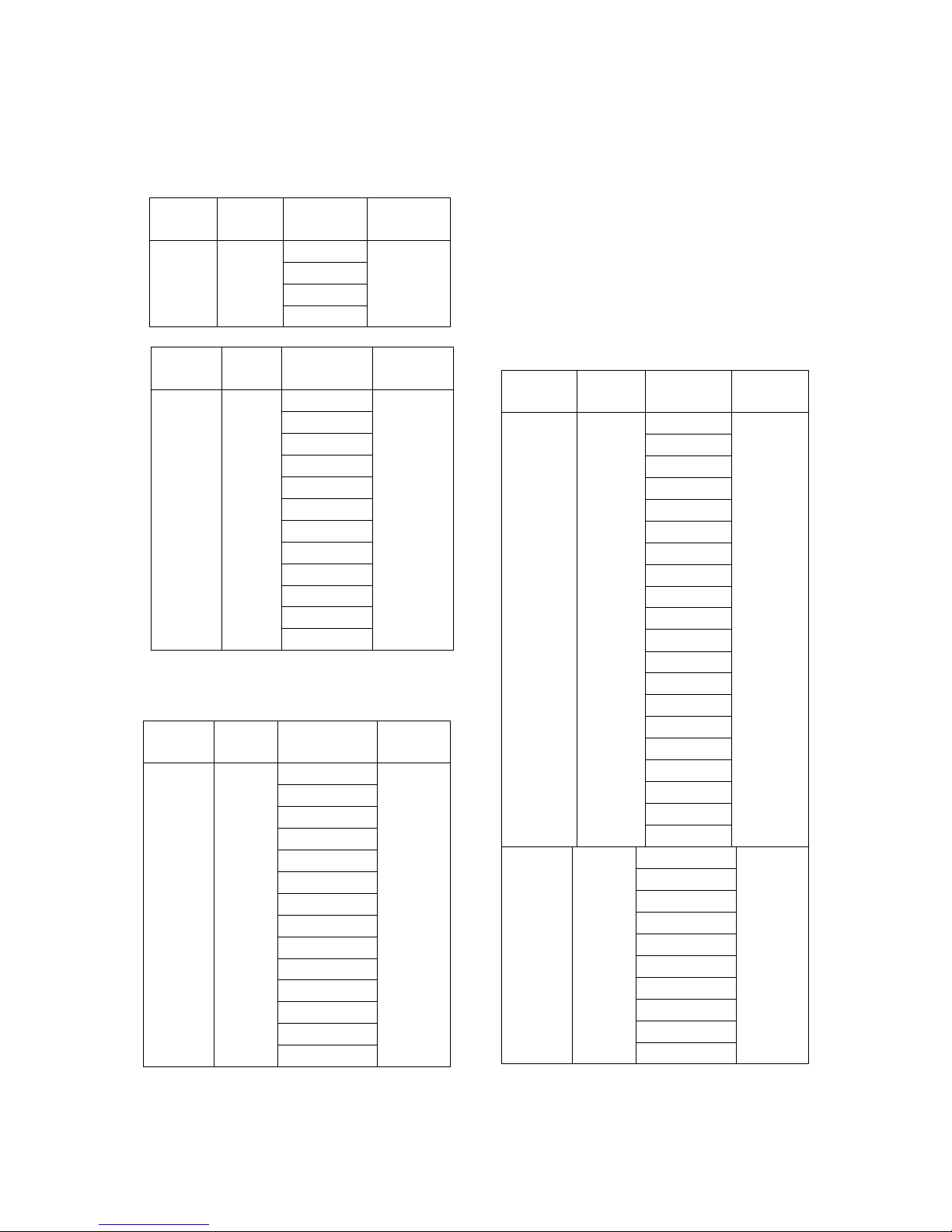
1. Indoor Unit Combination
Multi DC
Outdoor
Unit
Nominal
capacity
Suggested
Combination
Limit
1drive 2 5.2kW
12
None
9+9
9+12
12+12
Multi DC
Outdoor
Unit
Nominal
capacity
Suggested
Combination
Limit
1 drive 5 14kW
18+18
None
18+24
24+24
9+9+18
9+9+24
9+12+12
9+12+18
9+12+24
9+18+18
9+18+24
9+24+24
12+12+12
12+12+18
12+12+24
12+18+18
12+18+24
12+24+24
18+18+18
18+18+24
9+9+9+9
9+9+9+12
9+9+9+18
9+9+9+24
9+9+12+12
Multi DC
Outdoor
Unit
Nominal
capacity
Suggested
Combination
Limit
1drive 3 7.8kW
9+9
None
9+12
9+18
12+12
12+18
18+18
9+9+9
9+9+12
9+9+18
9+12+12
9+12+18
12+12+12
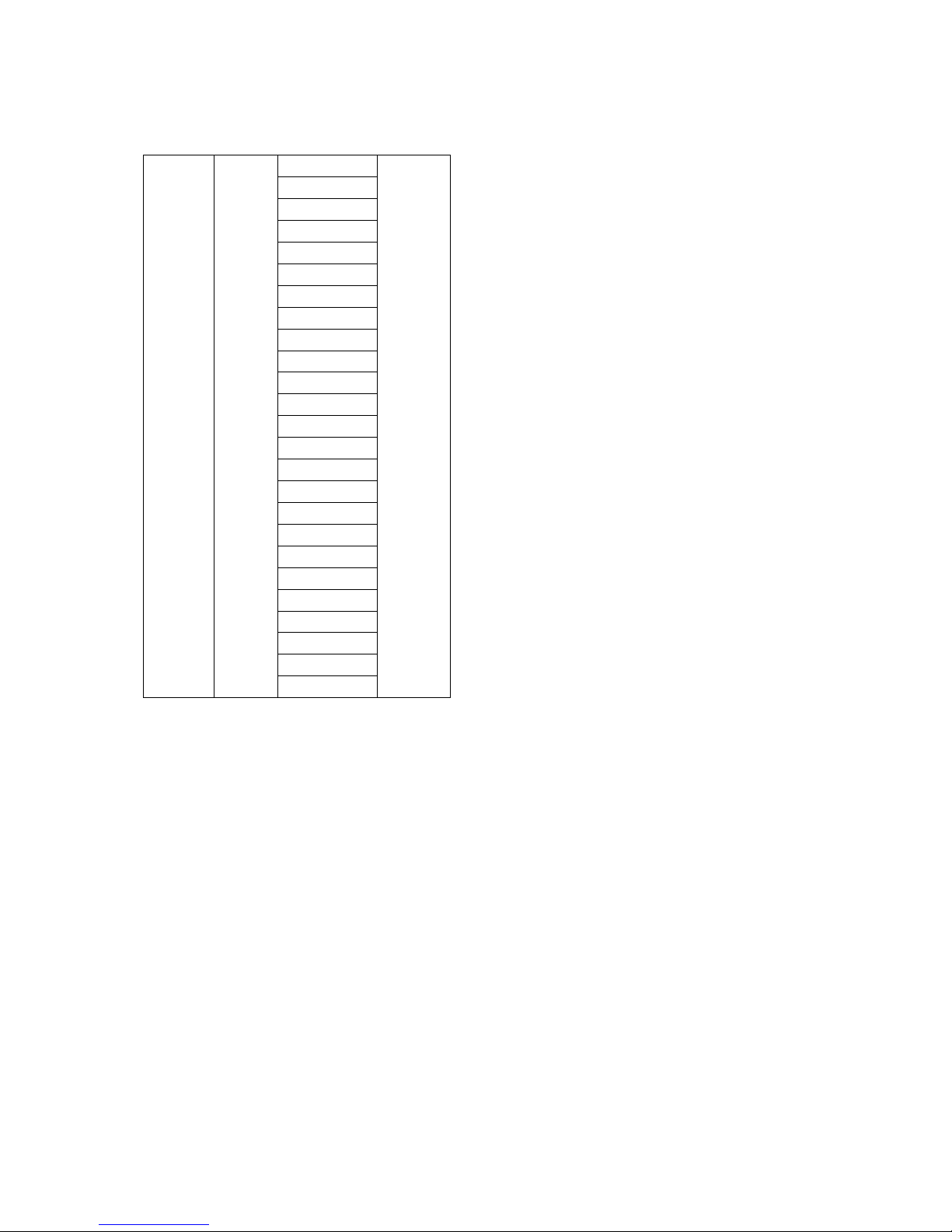
Multi DC
Outdoor
Unit
Nominal
capacity
Suggested
Combination
Limit
1 drive 4 10.5kW
9+18
None
12+12
12+18
18+18
9+9+9
9+9+12
9+9+18
9+12+12
9+12+18
9+18+18
12+12+12
12+12+18
12+18+18
9+9+9+9
9+9+9+12
9+9+9+18
9+9+12+12
9+9+12+18
9+12+12+12
12+12+12+12
Page 5
5
9+9+12+18
9+9+12+24
9+9+18+18
9+9+18+24
9+12+12+12
9+12+12+18
9+12+12+24
9+12+18+18
9+18+18+18
12+12+12+12
12+12+12+18
12+12+12+24
12+12+18+18
9+9+9+9+9
9+9+9+9+12
9+9+9+9+18
9+9+9+9+24
9+9+9+12+12
9+9+9+12+18
9+9+9+18+18
9+9+12+12+12
9+9+12+12+18
9+12+12+12+12
9+12+12+12+18
12+12+12+12+12
Page 6
6
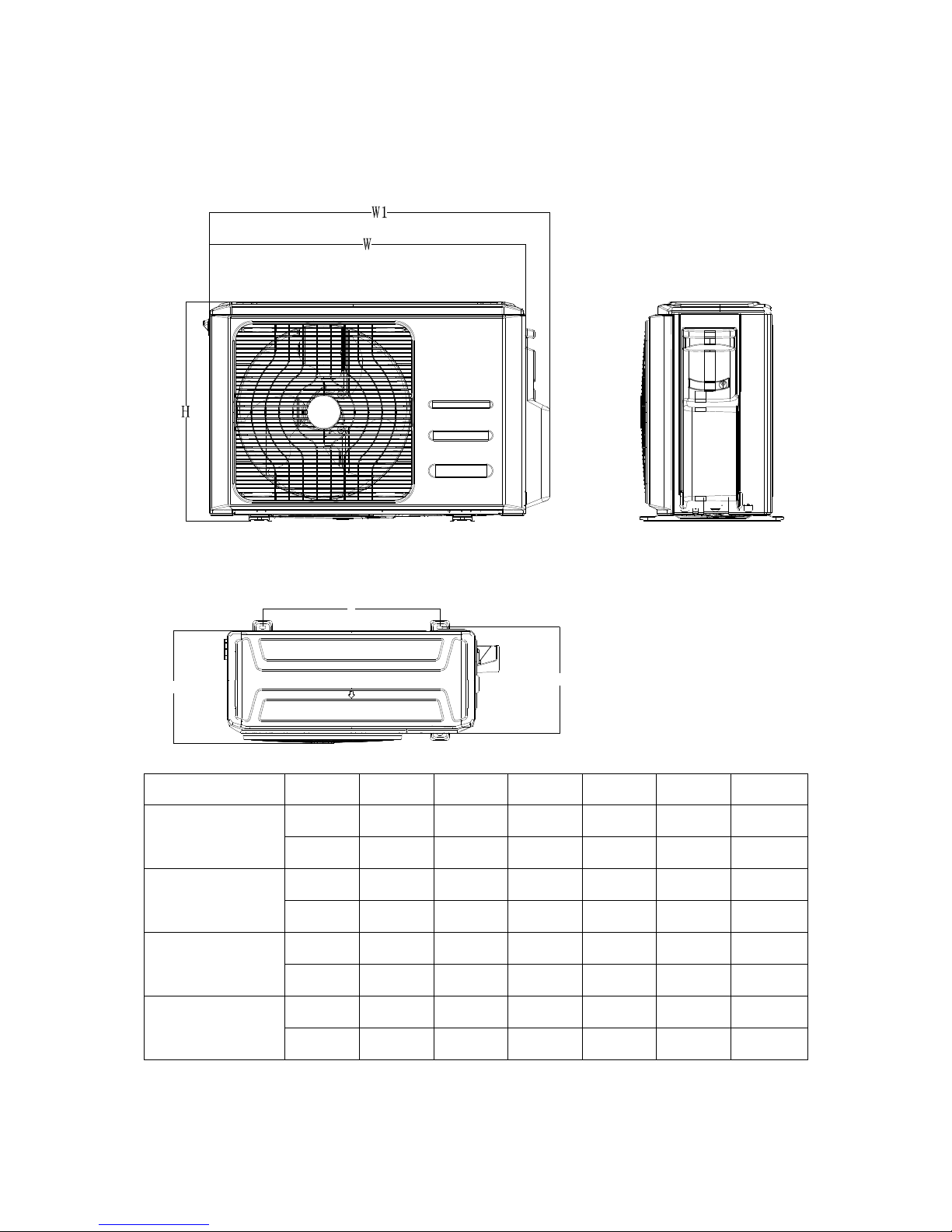
2. Dimension Of Outdoor Unit
Model
Unit:
W D H W1 A B
MCH2U-18PHH2
mm
845 363 702 923 540 350
inch
33.3
14.3
27.6
36.0
21.3
13.8
MCH3U-27PHH2
mm
946 410 810 1034 673 403
inch
37.2
16.5
31.9
40.6
26.5
15.9
MCH4U-36PHH2
mm
946 410 810 1034 673 403
inch
37.2
16.5
31.9
40.6
26.5
15.9
MCH5U-48PHH2
mm
952 415 1333 1060 634 404
inch
37.5
16.3
52.5
41.7
25.0
15.9
A
B
D
Page 7
7
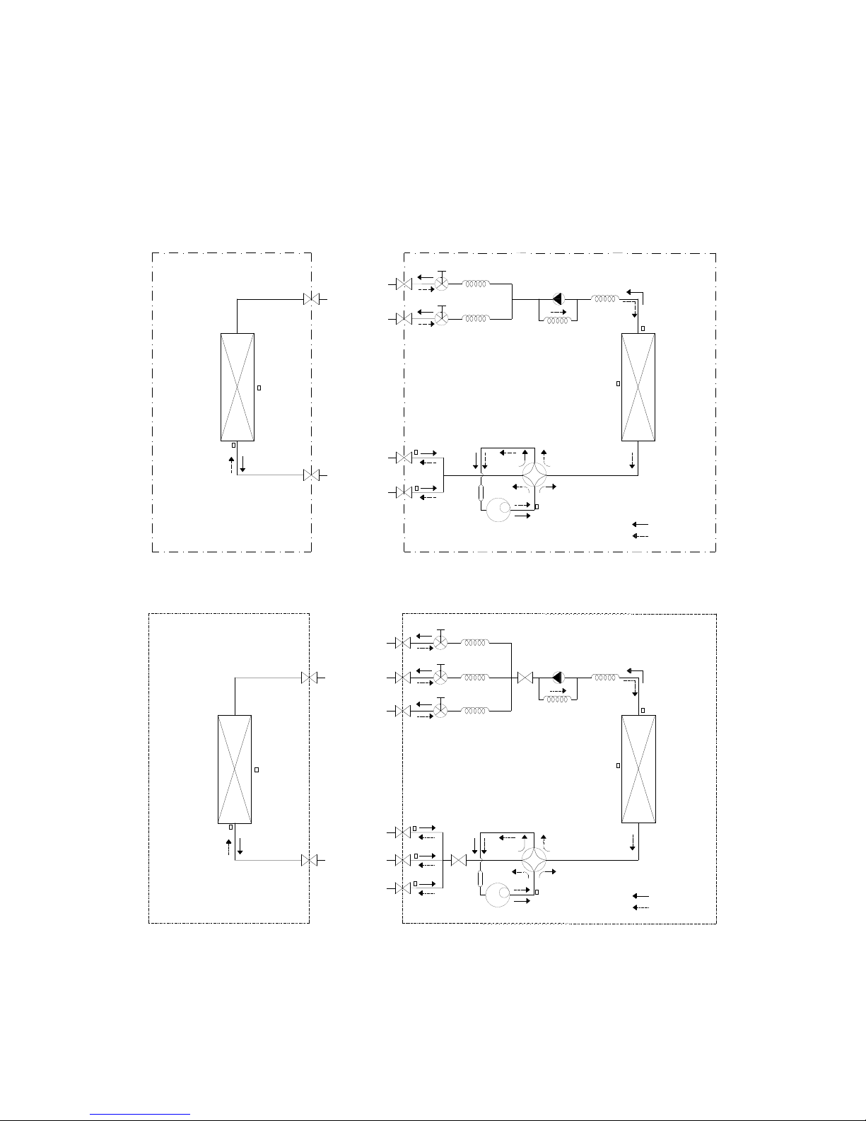
3. Refrigerant Cycle Diagram
3.1 Refrigeration circuit drawing of inverter 1 drive 2 type
LIQUID VALVE A
GAS VALVE A
HEAT
EXCHANGE
(EVAPORATOR)
HEAT
EXCHANGE
(CONDENSER)
Compressor
4-WAY VALVE
COOLING
HEATING
T2 Evaporator
temp. sensor
middle
T1 Room
temp. sensor
T3
Condenser
temp. sensor
T5 Discharge
temp. sensor
T4 Ambient
temp. sensor
INDOOR OUTDOOR
EXV A
CAPILIARY A
CHECK VALVE
CAPILIARY TUBE
EXV B CAPILIARY B
LIQUID VALVE B
GAS VALVE B
Accumulator
T2B-A
Evaporator
temp. sensor outlet
T2B-B
3.2 Refrigeration circuit drawing of inverter 1 drive 3 type
LIQUID VALVE A
GAS VALVE A
HEAT
EXCHANGE
(EVAPORATOR)
HEAT
EXCHANGE
(CONDENSER)
Compressor
4-WAY VALVE
COOLING
HEATING
T2 Evaporator
temp. sensor
middle
T1 Room
temp. sensor
T3
Condenser
temp. sensor
T5 Discharge
temp. sensor
T4 Ambient
temp. sensor
INDOOR OUTDOOR
EXV A CAPILIARY A
CHECK VALVE
CAPILIARY TUBE
EXV B
CAPILIARY B
LIQUID VALVE B
GAS VALVE B
EXV C
CAPILIARY C
LIQUID VALVE C
GAS VALVE C
Accumulator
T2B-A
Evaporator
temp. sensor outlet
T2B-B
T2B-C
Page 8
8
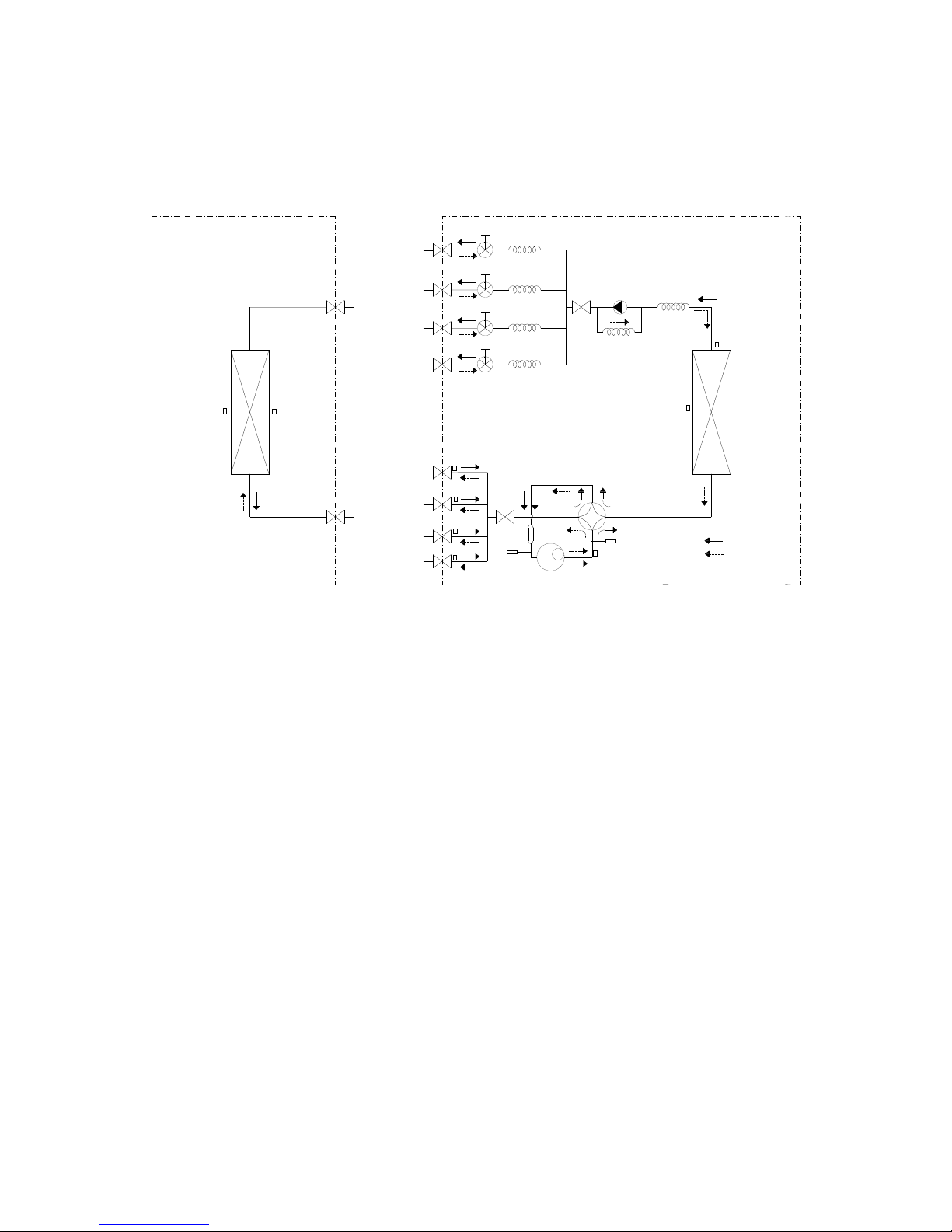
3.3 Refrigeration circuit drawing of inverter 1 drive 4 type
LIQUID VALVE A
GAS VALVE A
HEAT
EXCHANGE
(EVAPORATOR)
HEAT
EXCHANGE
(CONDENSER)
Compressor
4-WAY VALVE
COOLING
HEATING
T2 Evaporator
temp. sensor
middle
T1 Room
temp. sensor
T3
Condenser
temp. sensor
T5 Discharge
temp. sensor
T4 Ambient
temp. sensor
INDOOR OUTDOOR
EXV A
CAPILIARY A
CHECK VALVE
CAPILIARY TUBE
EXV B CAPILIARY B
LIQUID VALVE B
GAS VALVE B
EXV C
CAPILIARY C
LIQUID VALVE C
GAS VALVE C
EXV D CAPILIARY D
LIQUID VALVE D
GAS VALVE D
Accumulator
High pressure
switch
Low pressure
switch
T2B-A
Evaporator
temp. sensor outlet
T2B-B
T2B-C
T2B-D
3.4 Refrigeration circuit drawing of inverter 1 drive 5 type
Page 9
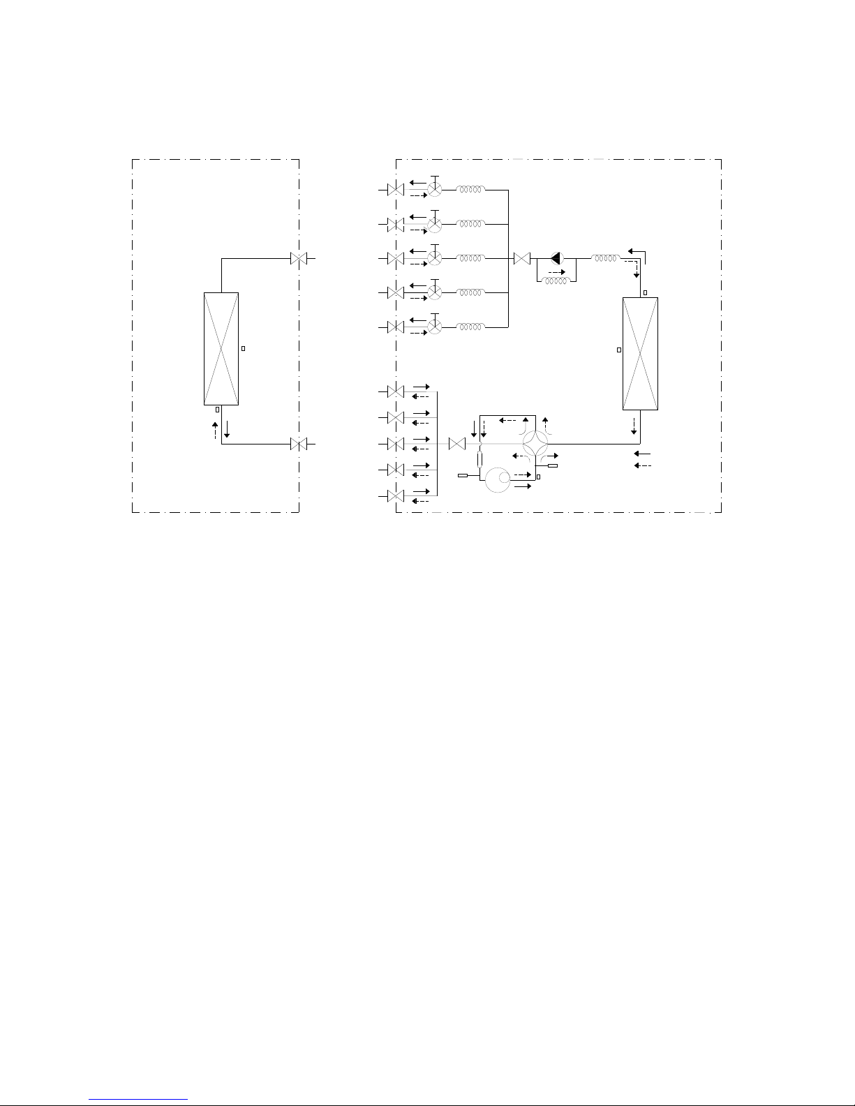
9
LIQUID VALVE A
GAS VALVE A
HEAT
EXCHANGE
(EVAPORATOR)
HEAT
EXCHANGE
(CONDENSER)
COOLING
HEATING
T2 Evaporator
temp. sensor
T1 Room
temp. sensor
T3
Condenser
temp. sensor
T4 Ambient
temp. sensor
INDOOR OUTDOOR
EXV A CAPILIARY A
CHECK VALVE
CAPILIARY TUBE
EXV B CAPILIARY B
LIQUID VALVE B
GAS VALVE B
EXV C
CAPILIARY C
LIQUID VALVE C
GAS VALVE C
EXV D
CAPILIARY D
LIQUID VALVE D
GAS VALVE D
EXV E
CAPILIARY E
LIQUID VALVE E
GAS VALVE E
Compressor
4-WAY VALVE
T5 Discharge
temp. sensor
Accumulator
High pressure
switch
Low pressure
switch
T2B-A
Evaporator
temp. sensor outlet
T2B-B
T2B-C
T2B-D
T2B-E
Page 10
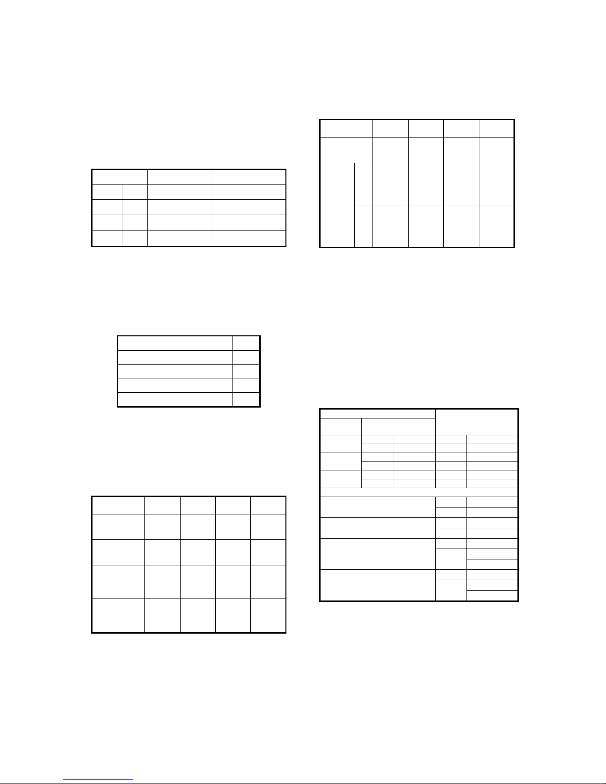
10
4. Installation Details
4.1 Wrench torque sheet for
installation
Outside
Torque
Additional
mm inch
N.cm N.cm
Ф6.35 1/4 1500(153kgf.cm) 1600(163kgf.cm)
Ф9.52 3/8 2500(255kgf.cm) 2600(265kgf.cm)
Ф12.7 1/2 3500(357kgf.cm) 3600(367kgf.cm)
4.2 Connecting the cables
The power cord connection should be
selected according to the following
specifications sheet.
Unit
AWG
1 drive 2 type (18K outdoor unit) 14
1 drive 3 type (27K outdoor unit). 14
1 drive 4 type (36K outdoor unit) 12
1 drive 5 type (48K outdoor unit) 10
For indoor unit and outdoor unit
connection line, 16AWG is ok for all.
4.3 Pipe length and the elevation
Maximum piping length and height
difference
1 drive 2 1 drive 3 1 drive 4 1 drive
5
Max. length
for all rooms
(m)
40
(131ft)
60
(197ft)
80
(262ft)
80
(262ft)
Max. length
for one IU
(m)
25
(82ft)
30
(98ft)
35
(115ft)
35
(115ft)
Max. height
difference
between IU
and OU (m)
15
(49.2ft)
15
(49.2ft)
15
(49.2ft)
15
(49.2ft)
Max. height
difference
between IUs
(m)
10
(33ft)
10
(33ft)
10
(33ft)
10
(33ft)
Additional refrigerant charge
1 drive 2 1 drive 3 1 drive 4 1 drive
5
Pre-charge
pipe length
(m)
15
(49.2ft)
22.5
(73.8ft)
30
(98.4ft)
37.5
(123ft)
Additio
nal
refriger
ant
charge
g 15 x
(length
for all
rooms -
15)
15 x
(length
for all
rooms
– 22.5)
15 x
(length
for all
rooms -
30)
15 x
(length
for all
rooms
– 37.5)
oz 0.161
x(lengt
h for all
rooms
– 49.2)
(0.161
x(lengt
h for all
rooms
– 73.8)
0.161x(
length
for all
rooms
– 98.4)
.0.161x
(length
for all
rooms
–123)
Caution:
● Refrigerant pipe diameter is different
according to indoor unit to be connected.
When using the extension pipe, refer to
the tables below.
● When refrigerant pipe diameter is
different from that of the outdoor unit
connector (18K indoor unit) an additional
adapter is required.
Indoor unit
Extension pipe
diameter (mm/inch)
Model
Pipe diameter
(mm/inch)
9K
Liquid 6.35(1/4) Liquid 6.35(1/4)
Gas 9.52(3/8) Gas 9.52(3/8)
12K 18K
Liquid 6.35(1/4) Liquid 6.35(1/4)
Gas 12.7(1/2) Gas 12.7(1/2)
24K
Liquid 9.52 (3/8) Liquid 9.52 (3/8)
Gas 15.9(5/8) Gas 15.9(5/8)
Outdoor unit union diameter (mm/inch)
1 drive 2
Liquid
6.35(1/4)
*2
Gas
9.52(3/8)
*2
1 drive 3
Liquid
6.35(1/4)
*3
Gas
9.52(3/8)
*3
1 drive 4
Liquid
6.35(1/4)
*4
Gas
9.52(3/8)
*3
12.7(1/2) *1
1 drive 5
Liquid
6.35(1/4)
*5
Gas
9.52(3/8)
*3
12.7(1/2) *2
Page 11
11
4.4 First-Time Installation
Air and moisture in the refrigerant system
cause the following problems:
● Increases in system pressure
● Increases in operating current
● Decreases in cooling and heating
efficiency
● Blocks in capillary tubing caused by
moisture in the refrigerant circuit freezing
● Corrosion of parts in the refrigerant
system caused by water
The indoor units and the pipes between
indoor and outdoor units must be tested for
leakages and evacuated to remove gas and
moisture from the system.
Gas leak check with soap water:
Apply soap water or a liquid neutral
detergent on the connections with a soft
brush to check for leakage in the pipe
connecting points. If bubbles emerge, the
pipes are leaking.
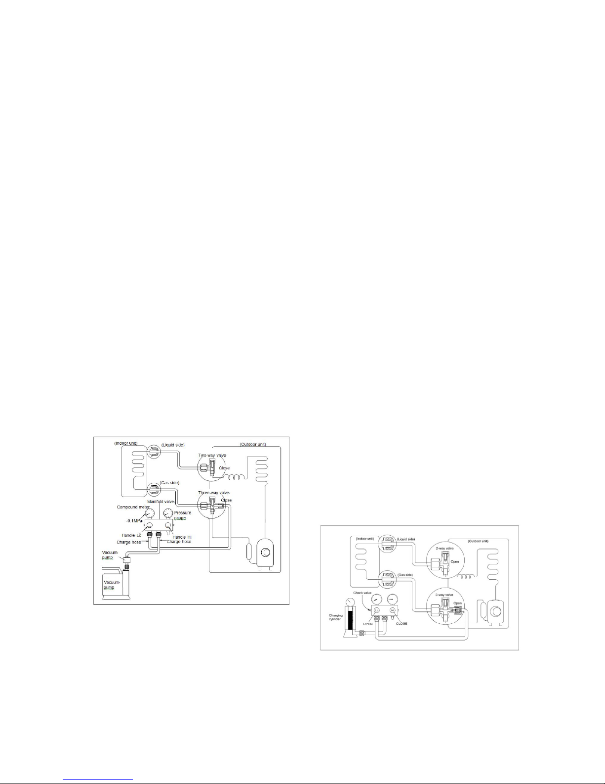
1. Air Purging Using the Vacuum Pump
1. Completely tighten the flare nuts on the
indoor and outdoor units. Confirm that
both the2-way and 3-way valves are set
to the closed position.
2. Connect the charge hose with the push
pin of the Handle Lo to the 3-way valve
gas service port.
3. Connect the charge hose of the Handle
Hi to the vacuum pump.
4. Fully open the Handle Lo of the manifold
valve.
5. Turn on the vacuum pump to begin
evacuation.
6. Conduct a 30-minute evacuation. Check
whether the compound meter indicates -
0.1Mpa(14.5Psi). If the meter does not
indicate -0.1Mpa(14.5Psi) after 30
minutes has elapsed, continue
evacuation for 20 more minutes. If the
pressure does not reach -
0.1Mpa(14.5Psi) after 50 minutes has
elapsed, check if there are any leaks.
Fully close the Handle Lo valve of the
manifold valve and turn off the vacuum
pump. After 5 minutes, confirm that the
gauge needle is not moving.
7. Turn the flare nut on the 3-way valve45°
counterclockwise for 6-7 seconds. Once
gas begins to come out, tighten the flare
nut. Make sure the pressure display on
the pressure indicator is higher than
atmospheric pressure. Then remove the
charge hose from the 3-way valve.
8. Fully open the 2-wayand 3-way valves
and securely tighten the cap on the 3way valve.
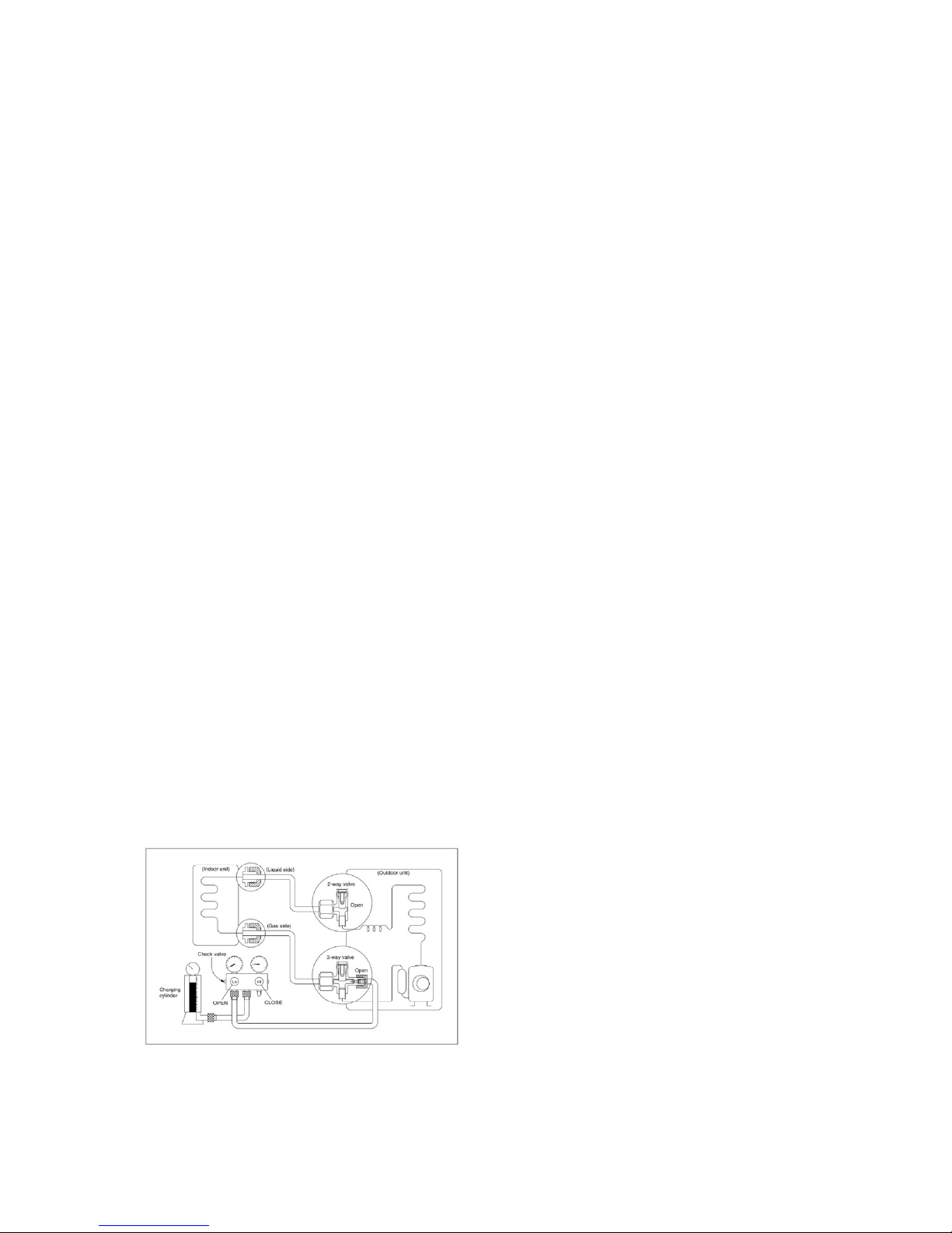
2. Adding refrigerant if the pipe length
exceeds chargeless pipe length
Procedure:
Page 12
12
1)
Connect the charge hose to the charging
cylinder and open the 2-way and 3-way
valves.
With the charge hose you disconnected
from the vacuum pump, connect it to the
valve at the bottom of the cylinder.
If the refrigerant is R410A, place the
cylinder bottom-up to ensure liquid charging
is possible.
2). Purge the air from the charge hose.
Open the valve at the bottom of the cylinder
and press the check valve on the charge set
(be careful of the liquid refrigerant).
3) Place the charging cylinder onto the
electronic scale and record the weight.
4) Turn on the air conditioner in cooling
mode.
5) Open the valves (Low side) on the charge
set. Charge the system with liquid refrigerant.
6).When the electronic scale displays the
proper weight (refer to the table), disconnect
the charge hose from the 3-way valve’s
service port immediately and turn off the air
conditioner before disconnecting the hose.
7). Mount the valve stem caps and the service
port
Use a torque wrench to tighten the service
port cap to a torque of 18N.m(13.27 ft·lbs).
Be sure to check for gas leaks.
4.5 Adding Refrigerant after Long-
Term System Operation
Procedure
1)
Connect the charge hose to the 3-way
service port and open the 2-way and 3-way
valve.
Connect the charge hose to the valve at the
bottom of the cylinder. If the refrigerant is
R410A, place the cylinder bottom-up to
ensure liquid charge.
2). Purge the air from the charge hose.
Open the valve at the bottom of the cylinder
and press the check valve on the charge set
to purge the air (be careful of the liquid
refrigerant).
3) Place the charging cylinder onto the
electronic scale and record the weight.
4) Turn on the air conditioner in cooling
mode.
5) Open the valves (Low side)on the charge
set and charge the system with liquid
refrigerant.
6).When the electronic scale displays the
proper weight (refer to the gauge and the
pressure of the low side), disconnect the
charge hose from the 3-way valve’s service
port immediately and turn off the air
conditioner before disconnecting the hose.
7). Mount the valve stem caps and the service
port.
Use torque wrench to tighten the service
port cap to a torque of 18N.m(13.27 ft·lbs).
Be sure to check for gas leaks.
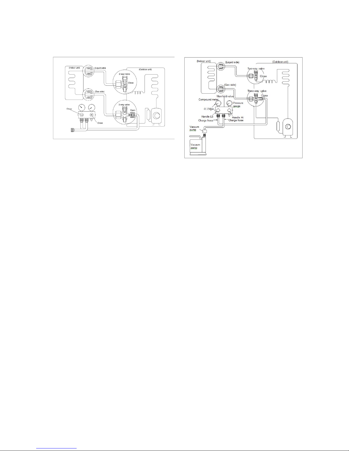
4.6 Procedure when servicing the
indoor unit refrigeration circuit.
1. Collecting the refrigerant into the
outdoor unit
Page 13
13
Procedure
1). Confirm that both the 2-way and 3-way
valves are set to the opened position
Remove the valve stem caps and confirm that
the valve stems are in the opened position.
Be sure to use a hexagonal wrench to operate
the valve stems.
2). Connect the charge hose with the push pin
of handle lo to the 3-way valves gas service
port.
3). Air purging of the charge hose.
Open the handle Lo valve of the manifold
valve slightly to purge air from the charge
hose for 5 seconds and then close it quickly.
4). Set the 2-way valve to the close position.
5). Operate the air conditioner at the cooling
cycle and stop it when the gauge indicates
0.1MPa.
6). Set the 3-way valve to the closed position
immediately
Do this quickly so that the gauge ends up
indicating 0.3 to 0.5Mpa.
Disconnect the charge set, and tighten the 2way and 3-way valve’s stem nuts.
Use a torque wrench to tighten the 3-way
valves service port cap to a torque of 18N.m.
Be sure to check for gas leakage.
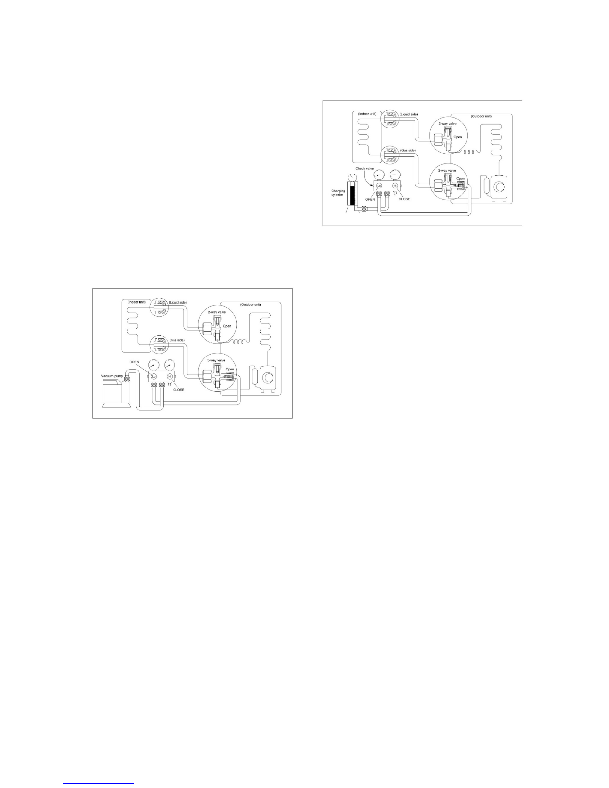
2. Air purging with vacuum pump
1) Completely tighten the flare nuts of the
indoor and outdoor units, confirm that
both the 2-way and 3-way valves are set
to the closed position.
2) Connect the charge hose with the push
pin of handle lo to the 3-way valves gas
service port.
3) Connect the charge hose of handle hi
connection to the vacuum pump.
4) Fully open the handle Lo of the manifold
valve.
5) Operate the vacuum pump to evacuate.
6) Make evacuation for 30 minutes and
check whether the compound meter
indicates -0.1Mpa. If the meter does not
indicate -0.1Mpa after pumping 30
minutes, it should be pumped 20 minutes
more. If the pressure can’t achieve -
0.1Mpa after pumping 50 minutes,
please check if there are some leakage
points.
Fully close the handle Lo valve of the
manifold valve and stop the operation of the
vacuum pump. Confirm that the gauge
needle does not move (approximately 5
minutes after turning off the vacuum pump).
7) Turn the flare nut of the 3-way valves
about 45° counterclockwise for 6 or
7seconds after the gas
coming out, then tighten the flare nut again.
Make sure the pressure display in the
Page 14
14
pressure indicator is a little higher than the
atmosphere pressure. Then remove the
charge hose from the 3 way valve.
8) Fully open the 2 way valve and 3 way
valve and securely tighten the cap of the
3 way valve.
4.7 Evacuation after servicing the
outdoor unit refrigeration circuit
1. Evacuation of the complete
refrigeration circuit, Indoor and outdoor
unit.
Procedure:
1). Confirm that both the 2-way and 3-way
valves are set to the opened position.
2). Connect the vacuum pump to 3-way
valve’s service port.
3). Evacuation for approximately one hour.
Confirm that the compound meter indicates -
0.1Mpa (500 Microns / 29.9 in,hg).
4). Close the valve (Low side) on the charge
set, turn off the vacuum pump, and confirm
that the gauge needle does not move
(approximately 5 minutes after turning off the
vacuum pump).
5). Disconnect the charge hose from the
vacuum pump.
2. Refrigerant charging
Procedure:
1). Connect the charge hose to the charging
cylinder, open the 2-way valve and the 3-way
valve.
Connect the charge hose which you
disconnected from the vacuum pump to the
valve at the bottom of the cylinder. If the
refrigerant is R410A, make the cylinder
bottom up to ensure liquid charge.
2). Purge the air from the charge hose
Open the valve at the bottom of the cylinder
and press the check valve on the charge set
to purge the air (be careful of the liquid
refrigerant).
3) Put the charging cylinder onto the
electronic scale and record the weight.
4). Open the valves (Low side) on the charge
set and charge the system with liquid
refrigerant
If the system cannot be charge with the
specified amount of refrigerant, or can be
charged with a little at a time (approximately
150g each time) , operating the air conditioner
in the cooling cycle; however, one time is not
sufficient, wait approximately 1 minute and
then repeat the procedure.
5).When the electronic scale displays the
proper weight, disconnect the charge hose
from the 3-way valve’s service port
immediately
If the system has been charged with liquid
refrigerant while operating the air conditioner,
turn off the air conditioner before
disconnecting the hose.
6). Mounted the valve stem caps and the
service port. Use torque wrench to tighten the
service port cap to a torque of 18N·m (13.27
ft·lbs).
Always leak check after servicing the
Page 15
15
refrigerant system.
For MCH3U-27PHH2/MCH4U36PHH2/MCH5U-48PHH2
There are one low-pressure centralized valve
and one high-pressure centralized valve, it will
be more time saving when vacuum and
recycle refrigerant. But refer to the previous
instruction when vacuum and recycle
refrigerant.
6. Electronic Function
6.1 Abbreviation
T1: Indoor ambient temperature
T2: Middle indoor heat exchanger coil
temperature
T2B: Indoor heat exchanger exhaust coil
temperature (located on the outdoor unit)
T3: Outdoor heat exchanger pipe
temperature
T4: Outdoor ambient temperature
T5: Compressor discharge temperature
6.2 Electric Control Working
Environment.
6.2.1 Input voltage: 230V.
6.2.2 Input power frequency: 60Hz.
6.2.3 Indoor fan standard working amp.: <1A
6.2.4 Outdoor fan standard working amp.:
<1.5A.
6.2.5 Four-way valve standard amp.: <1A.
6.3 Main Protection
6.3.1 Compressor Restart Delay
---- The compressor takes 1 minute to start
up the first time. Further restarts take 3
minutes.
6.3.2 Temperature Protection of
Compressor Discharge.
When the discharge temperature of the
compressor rises, the running frequency is
limited according to the following rules:
----If 105℃ (221 ℉)≦T5<110℃ (230 ℉),
maintain the current frequency.
Page 16
16
----If the temperature increase and T5≧110℃
(230 ℉), decrease the frequency to a lower
level every 2 minutes till to F1.
---If T5≧115℃ (239 ℉) for 10 seconds, the
compressor stops and then restart untill
T5<90℃ (194 ℉).
6.3.3 Fan Speed Malfunction
---- If outdoor fan speed is lower than
100RPM or higher than 2400RPM for 60
seconds or more, the unit stops and LED
displays E8 failure code.
6.3.4 Inverter Module Protection.
---- The inverter protection module ensures
that faults related to current, voltage, or
temperature does not damage the inverter.
If these protections are triggered, the A/C
unit stops and the LED displays the failure
code.
The unit restarts 3 minutes after the
protection mechanism has turned off.
6.3.5 Low Voltage Protection
V O LT A G E
N o l im it
V O L T _ LT M _F R EQ 1_ A D D
V O L T _L T M _F R EQ 2_ A D D
Note: If low voltage protection triggers and
voltage is not restored to normal within 3
minutes, the protection remains active
even after a machine restart.
6.3.6 Compressor Current Limit
Protection
The temperature interval for the current limit
is the same as the range of the T4
frequency limit.
Cooling mode:
CoolReturnI The difference between
current limit
and shutdown current
CoolT4Zone5I
Cooling T4≥50℃ current
limit value
CoolT4Zone4I
Cooling 49>T4≥45℃
current limit value
CoolT4Zone3I
Cooling 44>T4≥41℃
current limit value
CoolT4Zone2I
Cooling 40﹥T4≥33℃
current limit value
CoolT4Zone1I
Cooling 32>T4℃current
limit value
CoolStopI Cooling stop protection
current value
Heating mode:
℃
CoolT4Zone5I
50
49
45
CoolT4Zone4I
44
41
40
CoolT4Zone3I
33
32
CoolT4Zone2I
Page 17
17
℃
15
14 HeatT4Zone4I
10
9 HeatT4Zone3I
6
5 HeatT4Zone2I
HeatT4Zone1I
HeatReturnI The difference between
current limit
and shutdown current
HeatT4Zone4I
Heating
T4≥15℃
current
limit value
HeatT4Zone3I
Heating
14>T4≥10℃
current limit value
HeatT4Zone2I
Heating
9>T4≥6℃
current limit value
HeatT4Zone1I
Heating
5>T4
current limit
value
HeatStopI Heating stop protection
current value
6.3.7 Indoor / Outdoor Units
Communication Protection
If the indoor units do not receive the
feedback signal from the outdoor units for 2
consecutive minutes, the unit stops. The
unit displays the failure code.
6.3.8 High Condenser Coil Temp.
Protection
6.3.9 Outdoor Unit Anti-Freezing
Protection
When T2<4℃ for 250seconds or T2<0℃,
the indoor unit capacity demand is zero and
resumes normal operation when T2>8℃
and the protection time is no less than 3
minutes.
6.3.10 Oil Return
Rules for Operation
1. If the compressor frequency continues to
be lower than the frequency set for setting
time, the unit raises the frequency to the
frequency set for setting time and then
resumes with the former frequency.
2. The EXV continues at 300p while indoor
units maintain their operation.
If the outdoor ambient temperature is higher
than the set frequency during oil return, the
unit stops the oil return process.
6.3.11 Low Outdoor Ambient
Temperature Protection
When the compressor is off and T4 is lower
than -35℃ for 10 seconds, the unit stops
and displays “LP.”
When the compressor is on and T4 remains
lower than -40℃ for 10 seconds, the unit
stops and displays “LP.”
When T4 is no lower than -32℃ for 10
seconds, the unit exits protection.
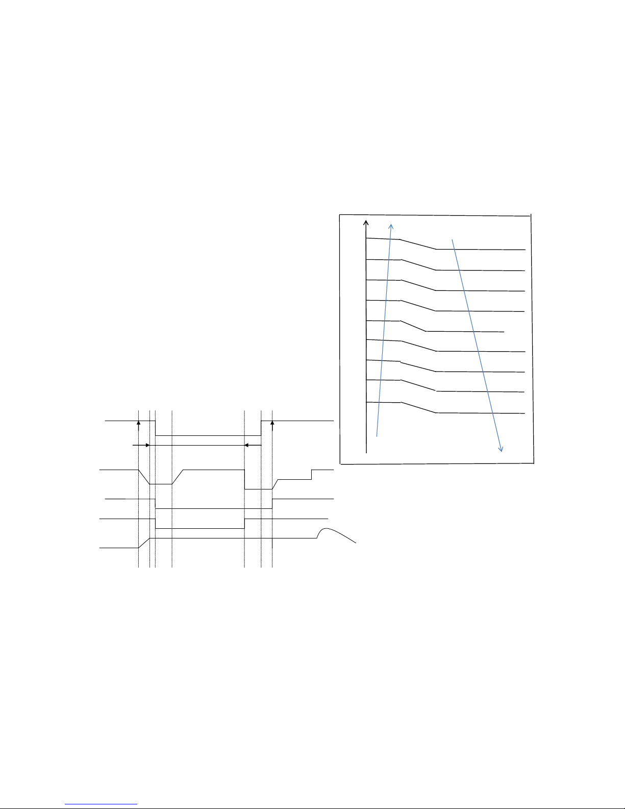
6.4 Control and Functions
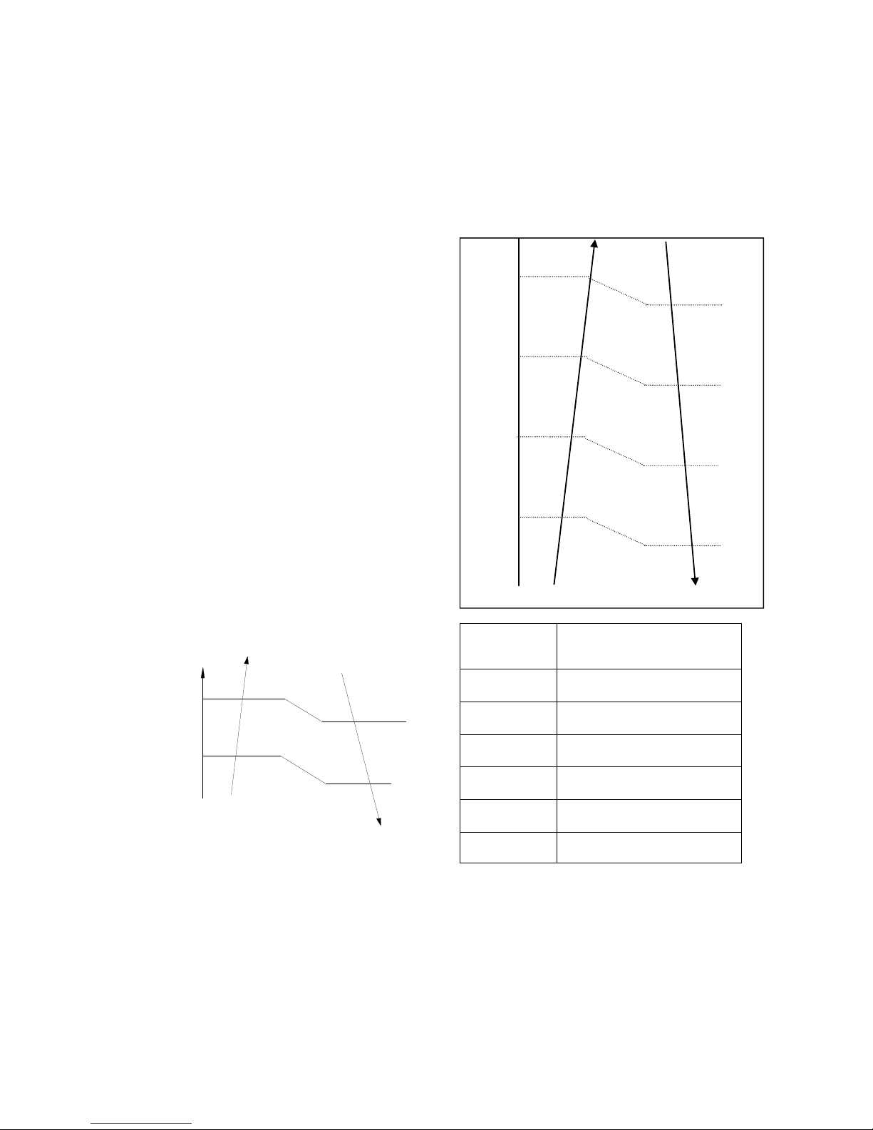
6.4.1 Capacity Request Calculation
Cooling Mode:
T3
Resume
Off
Decrease
Hold
Page 18

18
T1 Ts
3
1
1
e
c
a
4
2
0
2
3
0
1
f
d
b
Capacity area a b c d e f
Norm code
(N)
3 2 1.5 1 0.5 0
Model 9K 12K 18K 24K
HP 1.0 1.2 1.5 2.5
Note: The final result is an integer.
Use the following table and final capacity
request to confirm the operating
frequency.
Frequency
(Hz)
0
CO
OL_
F1
CO
OL_
F2
…
…
COO
L_F2
4
CO
OL_
F25
Amendatory
capacity
demand.
0 1 2
…
…
24 25
The maximum running frequency is
adjusted according to the outdoor ambient
temperature
℃
55
54 Fmax=
T4FREMAXC0
51.5
50.5 Fmax= T4FREMAXC1
45.5
44.5 Fmax= T4FREMAXC2
39
38 Fmax= T4FREMAXC3
33
32 Fmax= T4FREMAXC4
30
29 Fmax= T4FREMAXC5
22
20 Fmax= T4FREMAXC6
10
8 Fmax= T4FREMAXC7
0
-2 Fmax= T4FREMAXC8
-10
-12 Fmax= T4FREMAXC9
Fmax= T4FREMAXC10
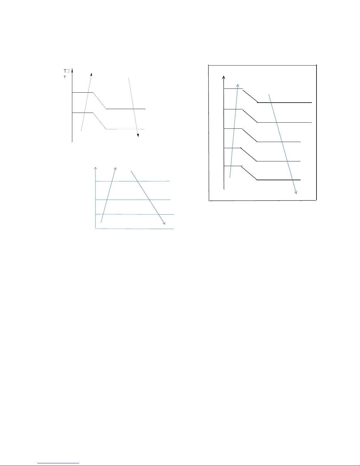
Heating Mode
T1 Ts
4
0
a
3
1
-1
3
1
2
0
b
c
d
e
f
2
Capacity area a b c d e f
Norm code (N) 3 2 1.5 1 0.5 0
Model 9K 12K 18K 24K
HP 1.0 1.2 1.5 2.5
Note: The final result is an integer.
Page 19
19
Then modify it according to a T2 average
(correction):
Note:Average value of T2:Sum T2 value of
all indoor units)/ (indoor units number
T2 average
Decrease frequency
47
Keep frequency
40 Increase frequency
Use the following table and final capacity
request to confirm the operating
frequency.
Frequency
(Hz) 0
HEA
T_F
1
HEA
T
_F2
…
HEA
T
_F24
HEA
T
_F2
5
Amendatory
capacity
demand.
0 1 2 … 24 25
The maximum running frequency is
adjusted according to the outdoor ambient
temperature
℃
34
33 Standby
28
27 Fmax=T4FREHEATMAX1
25
24 Fmax=T4FREHEATMAX2
22
21 Fmax=T4FREHEATMAX3
19
18 Fmax=T4FREHEATMAX4
17
16 Fmax=T4FREHEATMAX5
15
14 Fmax=T4FREHEATMAX6
12
11 Fmax=T4FREHEATMAX7
6
5 Fmax=T4FREHEATMAX8
1
0 Fmax=T4FREHEATMAX9
-3
-4 Fmax=F21
-7
-8 Fmax=F22
-11
-12 Fmax=F23
-15
-16 Fmax=F24
Fmax=F25
6.4.2 Defrosting Control
Conditions for Defrosting:
After the compressor starts and enters
normal operation, mark the minimum value
of T3 from the 10th to 15th minute as T30.
If any one of the following conditions is
satisfied, the unit enters defrosting mode:
1) If the compressor’s cumulative running
time reaches 29 minutes and T3< TCDI1
and T3+T30SUBT3ONE≦T30.
Page 20
20
2) If the compressor cumulative running
time reaches 35 minutes and T3< TCDI2
and T3+T30SUBT3TWO≦T30.
3) If the compressor cumulative running
time reaches 40 minutes and T3< -24C for 3
minutes.
4) If the compressor cumulative running
time reaches 120 minutes and T3<-15℃.
Defrost Stop Conditions
If any one of the following conditions is
satisfied, defrosting ends and the unit
returns to normal heating mode:
----T3 rises above than TCDE1℃.
----T3 remains at TCDE2℃ or above for 80
seconds.
----The machine runs for 10 consecutive
minutes in defrosting mode.
Defrosting Action:
off on
Cool-F9
10S 30S
TimeA
10S
4-way valve
defrosting Defrosting over
compressor
Indoor fan
Outdoor fan
EXV open
frequency
Max 10 minutes
frequency
Compressor stops
off
Anti-cold control
off
480P 480P for 240s
Condition of ending defrosting:
If any one of following items is satisfied,
defrosting will stop and the machine will turn
to normal heating mode.
① T3 > TempQuitDefrost_ADD ℃;.
② The defrosting time achieves 10min.
③ Turn to other modes or off.
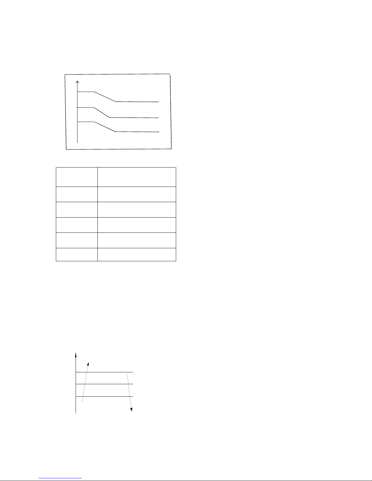
6.4.3 Outdoor Fan Control
6.4.3.1 Cooling Mode
Under normal operating conditions, the
system chooses the running fan speed
according to the ambient temperature:
O
utdoor temperature
℃
45
43 Supper high fan speed
28
26 High fan speed
25
23 Middle fan speed
22
20 Low fan speed
19
17 Supper low fan speed
10
9 Breeze fan speed
0
-1 F fan speed
-5
-6 G fan speed
-10
-11 H fan speed
I fan speed
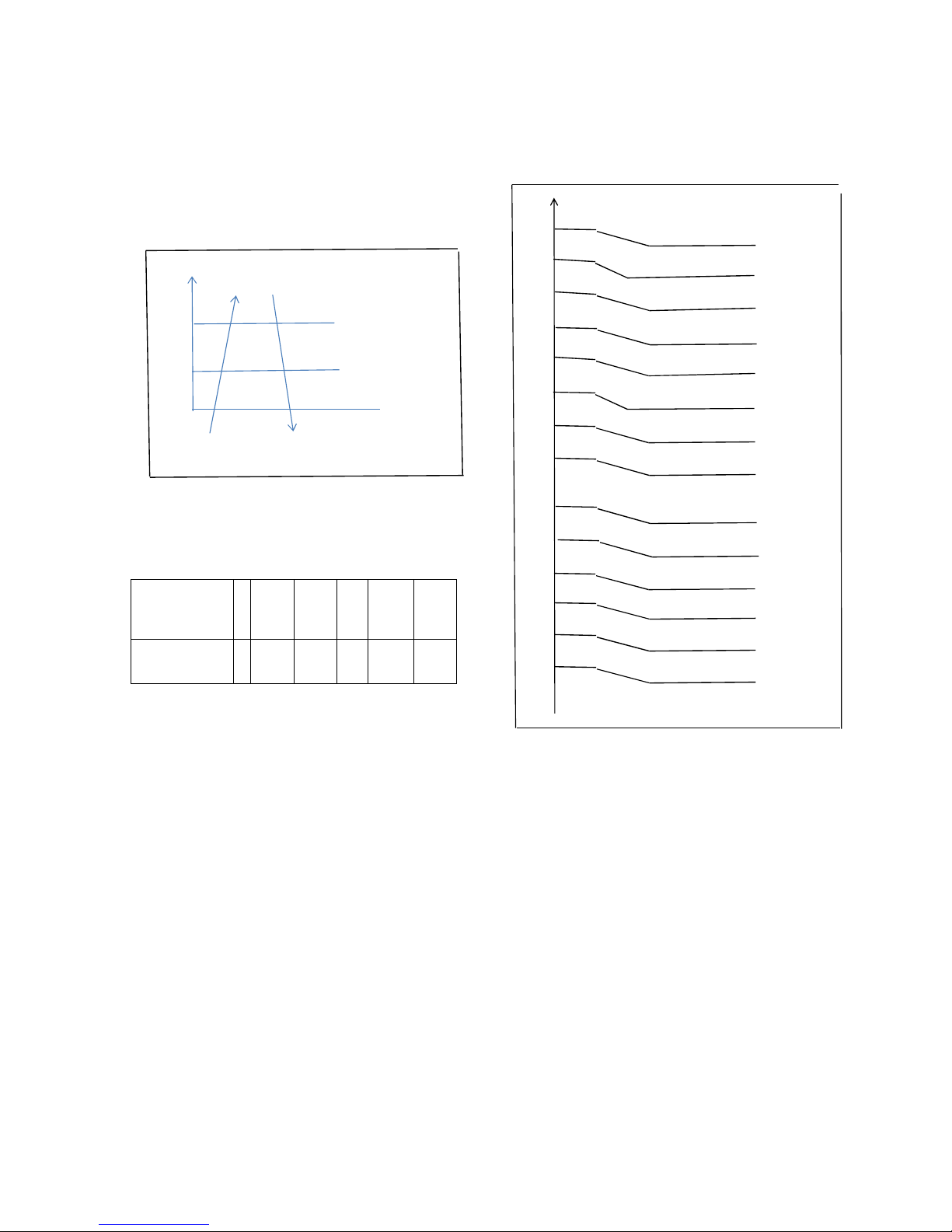
When low ambient cooling is in effect::
Outdoor fan speed control logic (low
ambient cooling)
When T4 <15 ℃ (59 ℉) and T3 < 30 ℃ (86
℉), the unit enters into low ambient cooling
mode. The outdoor fan chooses a speed
according to T3.
When T3≥38 ℃ (100.4 ℉) or when T4≥20 ℃
(68 ℉), the outdoor fan chooses a speed
according to T4 again.
Page 21
21
38
Exit low ambient cooling
mode, run with high fan
for 1 minute
Low
30
27
23
off
T3
Increase fan spe ed increase
Keep c urrent fan speed
Decrea se fan speed
Fan st op
LowCoolT3_ON
LowCoo lT3_Down
LowCoo lT3_OFF
6.4.3.2 Heating Mode
Under normal operating conditions, the
system chooses a running fan speed
according to ambient temperature:
Outdoor temperature℃
21
Breeze fan speed
19
18
Supper low fan speed
16
15
Low fan speed
13
12
Middle fan speed
10
0
High fan speed
-2
Supper high fan speed
6.4.4 Electronic Expansion Valve (EXV)
Control
1. EXV remains fully closed while the device
is powering up. EXV then remains on
standby with 350P open. It opens to the
target angle after the compressor starts.
2. EXV closes with -160P when the
compressor stops. Then it remains on
standby with 350P open. It opens to the
target angle after the compressor starts.
3. The action priority for the EXVs is A-B-CD-E.
4. The compressor and outdoor fan
commence operation only after EXV
initializes.
6.4.4.1 Cooling Mode
The initial open angle of the EXV depends on
the size of the indoor model. The adjustment
range is 100-400p.
When the unit has been running for 3
minutes, the outdoor receives indoor units'
capacity demand and T2B information and
then calculates their average. After
comparing each indoor’s T2B with the
Page 22

22
average, the outdoor gives the following
modification commands:
---- If the T2B>average, the relevant valve
needs to open 16p more
---- If the T2B= average, the relevant valve’s
open range remains as is
---- If the T2B<average, the relevant valve
needs to close 16p more
This modification is carried out every 2
minutes.
6.4.4.2 Heating Mode
The initial open angle of the EXV depends on
the size of the indoor model. The adjustment
range is 150-350p.
When the unit has been running for 3
minutes, the outdoor unit receives the indoor
units' indoor units' capacity demand and T2
information and then calculates their average.
After comparing each indoor unit’s T2 with
the average, the outdoor gives the following
modification commands:
----If the T2>average+2, the relevant valve
needs to close 16p more
---- If average+2≥the T2≥ average-2, the
relevant valve’s open range remains as is
----If the T2<average-2, the relevant valve
needs to open 16p more
This modification is carried out every 2
minutes.
6.4.5 Four-Way Valve Control
In heating mode, a four-way valve is opened.
In defrosting, a four-way valve operates
according to the current defrosting action.
In other modes, a four-way valve is closed.
When the unit is switched from heating to
other modes, the four-way valve turns off
after the compressor has been off for 2
consecutive minutes.
Failure or protection (excluding discharge
temperature protection and high/low
pressure protection) causes the four-way
valve to immediately shut down.
Page 23
23
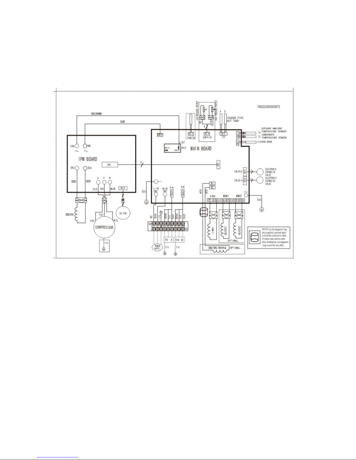
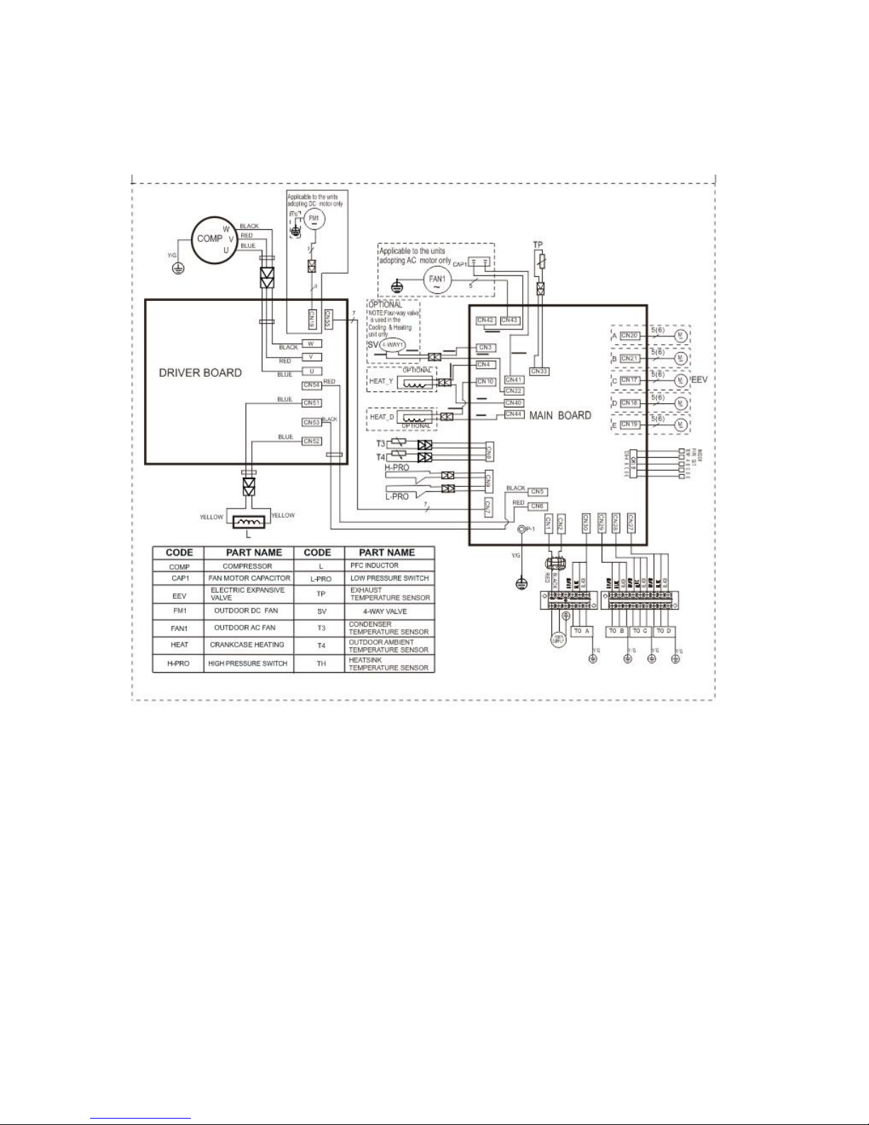
7. Wiring Diagrams
7.1 Wiring diagram of 1 drive 2 outdoor
MCH2U-18PHH2
Page 24
24
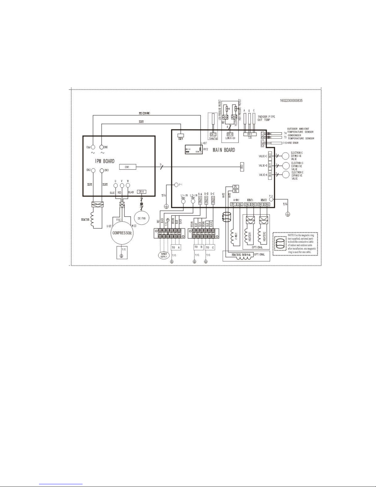
7.2 Wiring diagram of 1 drive 3 outdoor
MCH3U-27PHH2
Page 25
25
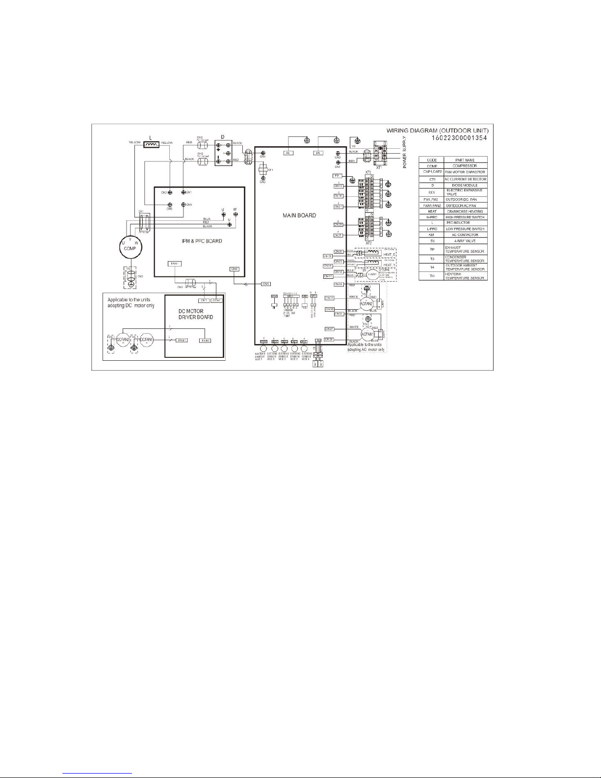
7.3 Wiring diagram of 1 drive 4 outdoor
MCH4U-36PHH2
Page 26
26
7.4 Wiring diagram of
MCH5U-48PHH2
Page 27
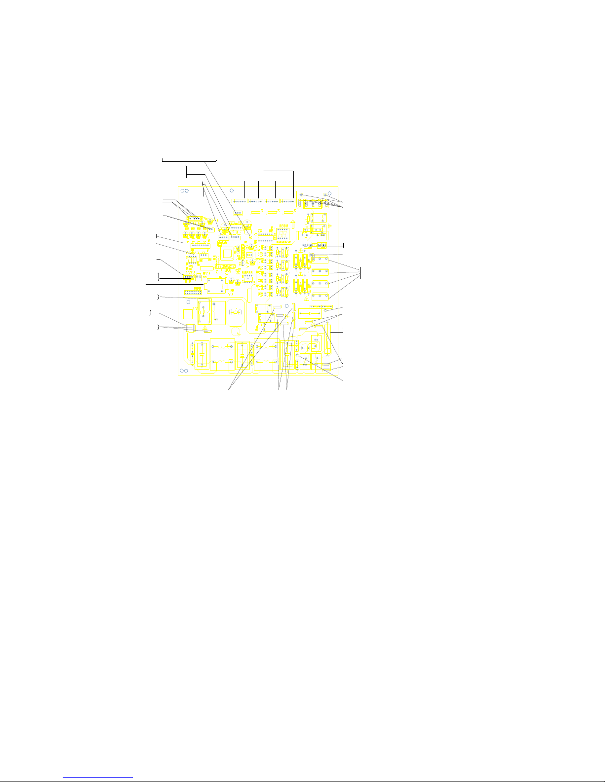
27
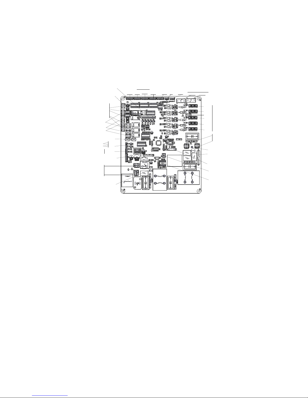
PCB board of MCH2U-18PHH2, MCH3U-27PHH2
S
N L
H
[1.4] 2015.08.27
1
P E Q
L-OUT
S N L
1
1
1
1
1
CE-KFR80W/BP2T4N1(AC MOTOR)-310.JD.FW.WXWKB.WP1-1
1
2
15
16
RUN
1
1
1
17122300001076
R121
CN36 C N35 CN34
CN33
CN32
P2
P1
C81
R119
C80
C50
C2
_1
D18
D16
D10
CN201
AS1
R116
R115
R114
R113
R112
R111
R98
R43
Q8
Q7
Q6
Q5
CN30
CN18
RY2
CN8
N
CN5
N
CN9
HEAT2
CN2
N
CN6
HEAT1
CN1
4-WAY
SW1
CN15
T2B
CN27
PFC-CONTROL
CN26
TestPort
L1
L2
R110
R109
R108
R107
R106
R105
R104
R103
R97
R57
R56
R55
IC9
D28
D27
C79
C78
R77
DSP1
CN11
AC MOTOR
R46
+
E7
+
E8
+
E11
R12
C11
+
-
~
~
RY8
C77
C76
C75
C74
C73
C72
D1
C71
IC1
R87
IC15
D2
ZR3
ZR2
ZR1
RY7
RY6
RY4
RY3
RY1
R102
R101
R100
R99
R96
R95
R94
R93
R92
R91
R90
R89
R88
R86
R85
R84
R83
R82
R81
R80
R79
R78R76
R75
R74
R73
R72
R71
R70
R69
R68
R67
R66
R65
R63
R62
R61
R60
R59
R58
R54
R53
R52
R51
R50
R48
R47
R45
R44
R42
R41
R39
R38
R37
R36
R35
R34
R33
R32
R31
R30
R28
R27
R26
R25
R24
R23
R22
R21
R20
R19
R18
R17
R16
R15
R14
R13
R11
R10
R9
R8
R7
R6
R5
R4
R3
R2
R1
Q4
Q3
Q2
Q1
PTC1
P-1
GND
IC16
IC14
IC11
IC3
FUSE2
T30A 250VAC
+
E13
+
E12
+
E10
+
E9
+E6+
E4
+
E2
+
E1
D19
D17
D13
D12
D11D9D8
D7
D6
D5
D4
D3
CT1
CONdebug1
CN25
S-A
CN24
D
CN23
S-B
CN22
C
CN21
TO-DRIVE
CN20
S-C
CN19
B
A
CN17
T3/T4
CN16
S-D
CN14
LOW/HIGH
CN13
FAN-C`
CN10
FAN-C
CN7
PAI QI
C59
C58
C57
C56
C55
C54
C53
C51
C49
C47
C46
C44
C43
C41
C40
C39
C38
C37
C35
C33
C32
C31
C30
C28
C26
C25
C24
C23
C22
C21
C20
C17
C16
C15
C14
C13
C12
C10
C9
C5
C4
C3
C1
D20
D15
C60
C61
C62
C63
C64
C65
C66
C67
C68
C69
C70
+
E14
+
E5
IC6
RY5
X1
IC17
C8
C7
C52
C48
C6
CN4
N-IN
CN29
N-OUT
CN28
CN12
CompTop
FUSE1
T5A 250VAC
R120
+
LED1
P-2
GND
CN3
L-IN
R117
R118
D33
D32
D31
R64
R49
R40
R29
IC13
IC12
IC10
IC8
IC7
IC5
IC4
IC2
C45 C36
C34
C29
C27
C19
C18
D34
C42
D14
CN4(N-IN)
power supply
208-230V AC
CN3(L-IN)
connect to the terminal
FUSE2
T30AL/250VAC
T5A 250VAC
FUSE1
CN9-CN8 (controled by RY4 relayer)
connect to the heater
when heater is ON, output 208-230V AC
CN6-CN5 (controled by RY3 relayer)
CN1-CN2 (controled by RY1 relayer)
connect to the 4-WAY
when 4-way is ON, output 208-230VAC
P-1(GND)
connect to the earth
connect to the Earth(Optional)
P-2(GND)
FOR EMC
P1
connect to P2
NO USE
CN20
CN23
CN25
CN16
CN30
connect to the terminal
24VDC Pulse wave betweene (+CN4)-(-CN30)
Signal wire
NO USE
CN36
CN35
CN34
CN10
CN13
FAN-C
FAN-C`
NO USE
CN18
Connect to Electric Expansion Valve
1
2
345
6
+12V DC
+12V DC
+12V DC pulse wave between (+4)-GND
+12V DC pulse wave between (+3)-GND
+12V DC pulse wave between (+2)-GND
+12V DC pulse wave between (+1)-GND
NO USENO USE
CN24 CN22
CN19
status light, by which you can judge the unit Normal or Error
LED1
(standby) Flashing once per second(low speed flashing)
(error) Flashing once p er half second (high speed flashing)
(running) aways on
NO USE
CN21
connect to IPM BOARD CN1
543
2
1
+12V
+5V
Low VOL supply
GND
(+4)-(-3) +5VDC Pulse wave
(+5)-(-3) +5VDC Pulse wave
CN27
room temp sensor RT
pipe temp sensor RT
CN17
Exaust temp sensor RT
CN7
N-OUT
CN15
NO USE
NO USE
CN28
CN14
NO USE
CN12
L-OUT connect to IPM BOARD CN4
connect to IPM BOARD CN5
(L-OUT)-(N-OUT) 208-230V AC
(L-OUT)-(N-OUT) 208-230V AC
connect to the comperssor top temp. sensor
0V DC
NO USE
CN33 connect to DR module RED wire
(L-OUT)-(N-OUT) 208-230V AC
CN32 connect to DR module BLUE wire
NO USE
test port
connect to detector
CN26
connect to DR module
or
Page 28
28
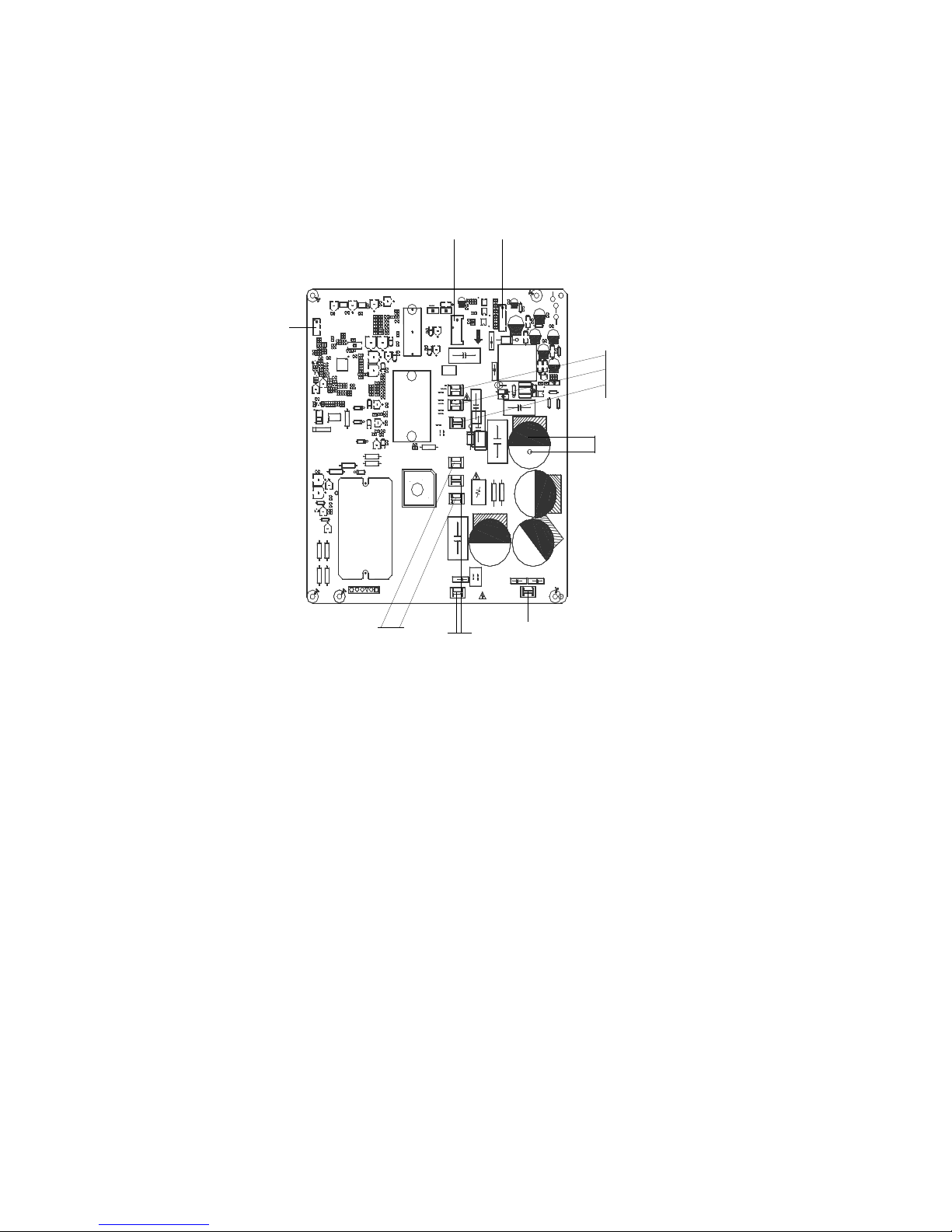
IPM board of MCH2U-18PHH2, MCH3U-27PHH2
BK
RD
BL
1
K
G
S
CTI 600V
17122000018251
W
V
U
17122000018251
250VAC
Time
Constant
IPM OCP
RD
BK
BL
64
16
J2
EU-KFR8 0W/BP 3(IR311+PS21997+
FAN_DC
SIM682 2+LOCK ).D.13.WP2-1
Pin1
CN7
CN9
CN10
5V→3.3V
3.3V→1.8V
U
V
W
3
2
4
CAUTION HI GH VOLTAGE
1
1
2 4
+
+
CN3
NTC1
R3
D2
41
CN8
Program_Debug
6
1
Online writing
R168
+
DZ10
+
DZ9
+
DZ8
R2
PTC2
J7 J6
J9
J8
F_DC Fan
R167
R166
R165
C81
CN1
CN11
ZR3 ZR2
ZR1
C13
R46
+
E15
C85
IC21
7805
C82
R164
C103
R
1
6
3
R162
R
1
6
1
IC2
CN4
L
CN5
N
CN2
R1_1
R1_2
R1_3
R1_4
R17
IC19
7805
CN13
D7
+
DZ6
C99
IC6
7815
R87
D14
R125
IC10 24LC2 5624LC08
C63
C50
C49
CY1
DZ4
R124
C1
+
E6
+
E5
PTC1
FUSE1
T/3.15A
- +
~
BR2
IC3
T1
IPM1
R121
R67
R90
R84
C7 C12
R
1
1
5
R114
R113
R112
R111
R110
R109
R108
R107
R105
R102
R101
R100
R99
R
9
7
R96
R95
R94
R93
R92
R91
R89
R88
R86
R83
R82
R81
R80
R79
R77
R76
R75
R74
R73
R72
R71
R69
R68
R65
R64
R63
R62
R61
R58
R54
R53
R51
R49
R48
R47
R44
R43
R40
R38 R37
R36
R35
R34 R33 R 31
R30
R29
R28
R27
R26
R25
R
2
4
R23
R21
R20
R19
R18 R16
R15
R14
R13
R12
R11
R10
R9
R8R7R6
R4
Q2
OSC1
LED2+LED1
1
17
49
33
IC14
IC13
IC12
IC11
IC9
IC8
IC7
IC4IC1
C100C101
C4
C95
C96
C97
C98
+
E14
+
E13
E12
+
E11
+
+
E9
+
+
E8
C102
+
E4
+
E1
+
DZ5
+ DZ1
D19
D13
D12
+
D11
D6
+
D3
D1
C78
C77
C76
C75
C74
C73
C72
C71
C70
C69
C68
C67
C
6
6
C65
C64
C
6
2
C
6
1
C60
C59
C58
C57
C56
C54
C53
C
5
2
C51
C47
C46
C45
C44
C43
C42
C41
C40
C39
C37
C36
C35
C34
C33
C32
C31
C30
C29
C28
C27
C26
C25
C24
C23
C22
C21
C20
C19
C18
C17
C16
C
1
5
C14
C11
C10
C8
C5
C3
C2
IGBT1
D20
C6
IC15
IPM2
SIM6822M
+
E2
R106
CN16
R118
R85
R119
R120
R57
+
E3
R117
R116
R122
R123
R70
R78
C38
R50
R66
D9
J4
C80
C55
R138
R137
R136
C84
R135
R143
R133
R132
IC17
Q6
IC16
C79
C83
IC5
R145
Q8
Q9
R144
R141
R148
R147
R146
C90
R98
J3
E27
7815
+
DZ7
E26
+
E25
R
1
3
9
R
1
6
0
C91
D21
R158
R157
R156
R159
C
9
2
IC18
R127
C48
R140
R39
R41
D22
R42
D23
R10_1
R10_2
R10_3
R11_1
R11_2
R11_3
J2
R
1
3
4
BR1
C9
C86
L1
R52
CN_COMP
CN_Reactor
R45
R1
J1
J5
R32
R59
R22
Q1
R103
J
1
0
J12
J11
R83_1
J13
R5
power supply
CN4(L)-CN5(N)
connect to the m ain board no use
fuse1 T/3.15A
Compressor drive EEPROM
online writing
Compressor driv e Program
Debug
DC Fan Driver IP M module
10-200VAC (run ning)
0VAC (standby)
connect to the DC FAN motor
TXD
+12V DC
+5V DC
GND For +12V
RXD
5
4
3
2
1
no use
DC Fan fuse for DC FAN
T/3.15A
10-200VAC (run ning)
0VAC (standby)
connect to the c ompressor
no use
connect to the Reactor
Page 29
29
PCB board of MCH4U-36PHH2
N
L
SHOW/SW
EARTH
[1.4]2014.06.26
EU-KFR105W/BP3T5N1-350S.D.13.WP1-1
L-OUT
N-OUT
CONNECT TO INVERTER driver
HIGH
LOW
T2B-E
T2B-D
T2B-C
T2B-BT2B-A
TP
T4 T3
S-E
S-D
S-C
S-B
S-A
FAN_OUT
FAN_IN
Q
E
P
AB
C
D
E
202302141206
CN19
D4
R134
R133
R89
R37
+
E12
+
E15
CN10
N
C18
CN9
ZR3
ZR2
ZR1
X1
S
RY8
RY7
RY6
RY5
RY3
RY2
R213
R212
R211
R210
R180
R170
R140
R131
R130
R129
R128
R127
R126
R125
R124
R123
R121
R120
R118
R117
R116
R115
R114
R113
R112
R111
R110
R109
R108
R107
R106
R105
R104
R103
R102
R101
R100
R99
R98
R96
R95
R94
R93
R92
R91
R90
R88
R81
R80
R79
R78
R77
R76
R75
R74
R73
R72
R71
R70
R69
R68
R67
R66
R65
R64
R63
R62
R61
R60
R59
R58
R57
R56
R55
R54
R53
R52
R51
R50
R49
R48
R47
R46
R45
R44
R43
R42
R41
R40
R39R38
R36
R35
R34
R33
R32
R31
R30
R29
R28
R27
R26
R25
R24
R23
R22
R21
R20
R19
R18
R17
R16
R15
R14
R13
R12
R11
R10
R9
R8
R7
R6
R5R4R3
R2
R1
Q5
Q2
PTC1
LED1
L3
IC30
IC22
IC21
IC20
IC19
IC18
IC17
IC16
IC15
IC14
IC13
IC12
IC10
IC9
IC8
IC7 IC6
IC5
IC2
IC1
FUSE2
5A/250V
FUSE1
T30A/250V
E21
E20
+
E19
+
E16+E14
E13
E11
E9
E8
E5
E4
E3
E1
DSP1
DSA1
D28
D27
D26
D25
D24
D23
D22
D21
D20
D19
D18
D17
D16
D15
D14
D13
D12
D11
D10
D9
D8
D7
D6
D5
D3
D2
D1
CONdebug
CN44
HEAT2
CN43
FAN
CN42
C
CN41
C
CN40
HEAT1
CN34
CN33
CN30
CN29
CN28
CN27
CN26
CN22
4-WAY
CN20
CN18
CN17
CN16
CN14
CompTop
CN12
CN11
CN8
CN6
CN5
CN4
N
CN3
N
CN2
N-IN
CN1
L-IN
C103
C98
C97
C96
C95
C94
C93
C92
C91
C90
C72
C70
C69
C68
C67
C66
C65C64
C62
C61
C60
C59
C58
C57
C56
C55
C54
C53
C52
C51
C50
C49
C48
C47
C46
C45
C44
C43
C42
C41
C40
C39
C38
C37
C36
C35
C34
C33 C32
C31
C30
C29
C28
C27
C26
C25
C24
C23
C22
C21
C20
C19
C17
C16
C15
C14
C13
C12
C11
C10
C9C8C7
C6
C5
C4
C3
C2
C1
JP1
JP2
D29
D30
CN23
SSR1
CN7
CN13
P-1
L1
R82
R83
R84
R85
R86
R87
R97
R119
R122
R132
CN35
N
CN37
FAN-L
Q3
Q6
Q7
Q8
Q9
CN36
FAN-H
E2
IC3
Q1
Q4
IC4
ZR4
RY4
CN32
CN38
L2
R135
SW1
CN21
Electric Expansion
Value B
Electric Expansion
Value E
Electric Expansion
Value D
Electric Expansion
Value C
Electric Expansion
Value A
485
communication
testPort
connect to detector
external drive DC fan
motor input terminal
external drive DC fan
motor ouput terminal
current loop
communication A
current loop
communication B
current loop
communication C
current loop
communication D
current loop
communication E
digital display
Fuse
T30A/250V
connect to high and low
pressure sensor
connect to
trmp. sensor
Fuse 5A/250V
connect to earth
CN23 reserve
digital display button
test report
connect to detector
CN43-5,CN43-1/CN41,CN42
AC fan motor capacitor
connector
CN43-4/CN37 CONNECT TO
AC FAN MOTOR(LOW SPEED)
CN43-3/CN36
AC fan motor low speed
connector
CN43-2/CN35
AV fan motor N phase
current loop
communication C
Signal wire
24VDC Pulse wave
connect to the terminal
connect to the terminal
208-230V AC
power supply
room temp sensor
pipe temp sensor
(3.3V)
(3.3V)
high pressure sensor
low pressure sensor
Connect to the Indoor evap.pipe
out temp. sensor
T2B-A、T2B-B、T2B-C、T2B-D、T2B-E
+12V DC pulse wave between (+1)-GND
+12V DC pulse wave between (+2)-GND
+12V DC pulse wave between (+3)-GND
+12V DC pulse wave between (+4)-GND
+12V DC
+12V DC
6 5 4 3 2 1
when 4-way is ON, output 208-230VAC
connect to the 4-WAY
when heater is ON, output 208-230V AC
connect to compressor heater
CN44 L
CN10 N
CN40 L
CN4 N
CN22 L
CN3 N
connect to exhaust
temp. sensor
connect to the terminal
208-230V AC
external drive DC fan
motor connector
T3
T4
electric
heater1
electric
heater 2
Page 30
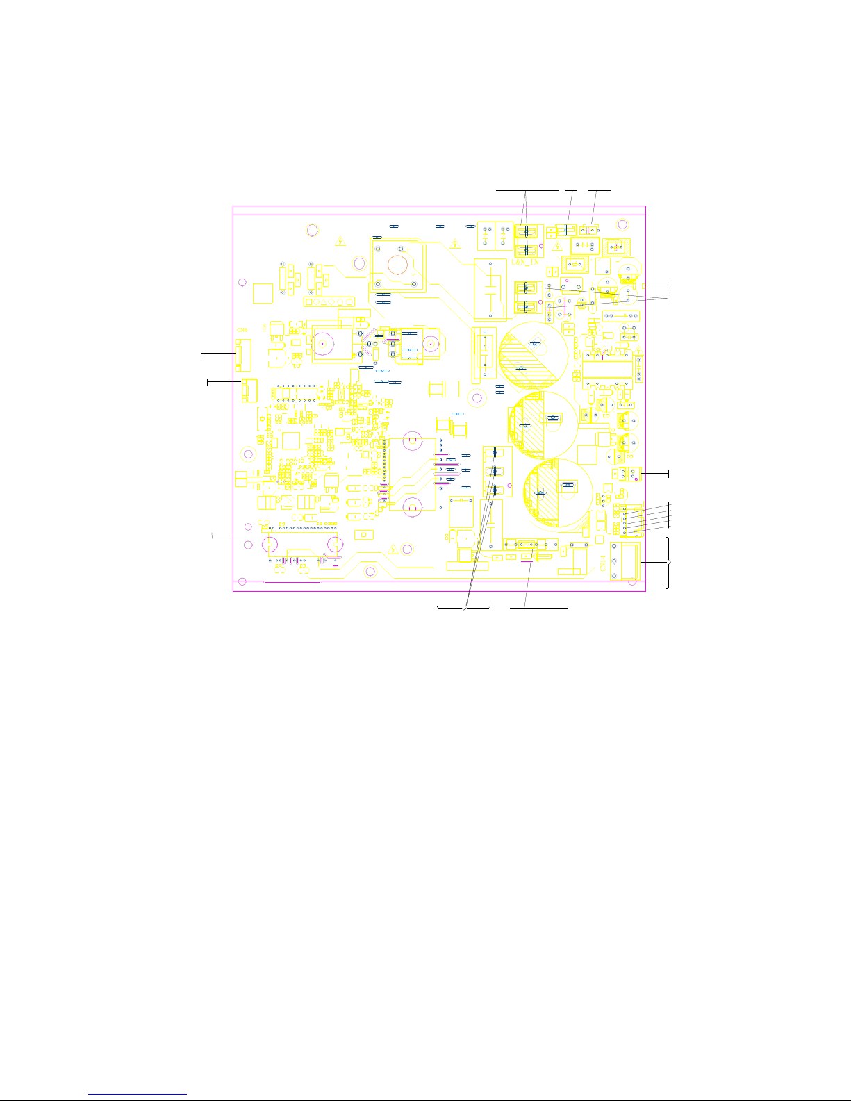
30
IPM board of MCH4U-36PHH2
202302141237
PFC-L2
[1.6]2014.10.16
EU-KFR105W/BP2T3N1-350(767).D.13.MP2-1
PFC-L1
CN58
EARTH
C57
C56
6
J146J15
R65
C55
C53
E31
C50
D7
C49
+
E30
C47
C9
ZR1
DZ3
R8
E3
E2
CN55
TO-MAIN
E23
C46
R13
IC3
C113
W
V
U
1
6 7
1011
12
1314
15
3
8
T1
R208
R207
R206
R205
R204
R203
R202
R198
R197
R196
R194
R192
R187
R186
R185
R184
R183
R182
R181
R180
R179
R175
R174
R173
R170
R163
R160
R150
R147
R146
R144
R143
R141
R140
R139
R137
R135
R133
R132
R131
R130
R129
R128
R127
R126
R125
R124
R119
R114
R111
R107
R104
R96
R92
R91
R90
R82
R80
R79
R78
R77
R76
R75
R66
R63
R62
R61
R60
R59
R58
R57
R56
R55
R54
R53
R52
R51
R50
R49
R48
R47
R46
R45
R44
R43
R42
R41
R40
R39
R38
R37
R36
R35
R33
R32
R31
R30
R29
R27
R26
R25
R24
R23
R22
R21
R20
R19
R18
R17
R15
R14
R12
R11
R10
R9
R7
R5
R2
R1
Q2
OSC1
+
LED4+LED3
JR1
J201
6
J1
IPM2
1
IPM1
1
17
49
33
IC20
IC17
IC16
IC15
24C256
IC1424C08
IC10
IC7
IC4
IC2
E34
E33
E27
E25
+
E24
+
E22
+
E21
+
E20
+
E17
E16
E15
E14
E13
E12
E10
E9
+
E8
+
E7
+
E6
+
E5
E4
E1
+
DZ9
+
DZ8
+
DZ7
+
DZ6
+
DZ1
D26
D14
D13
D12
D11
D10
D9
D8
D6
D5
D4
D3
D2
CN57
1
CN56
CN54
L-IN2
CN53
N-IN2
CN52
CN51
CN19
OUTFAN(DC)
C124
C123
C122
C121
C120
C119
C118
C117
C116
C114
C111
C109
C108
C107
C106
C105
C104
C103
C102
C101
C100
C99
C97
C94
C82
C79
C78
C77
C76
C72
C71
C70
C69
C67
C66
C65
C64
C61
C60
C59
C54
C51
C40
C39
C38
C36
C33
C32
C31
C30
C29
C26
C25
C24
C23
C22
C21
C20
C19
C18
C17
C16
C15
C14
C13
C12
C11
C8
C7
C6
C5
C4
C3
C2
C1
BR1
R3
R4
R6
R16
C27
C28
+
E18
C10
+
E19
C34
+
D1
+
D15
+
D16
22
44
23
IC1
C52
D17
R28
6J36
J4
6
J2
6
J5
6
J6
6
J7
6
J8
6J96
J10
6
J11
6
J12
6
J13
C35
C37
C41
C42
C43
C44
C45
E26
E28
E29
IC11
IC12
R34
R64
C48
E11
CN53
power supply
connect to the terminal
208-230V AC
CN54
CN51
CN52
PFC
inductance
terminal
CN58
EATTH
+
210-300VDC (Running)
CAPACITOR Voltage
290-330VDC (standby)
CN55
TO MAIN
CN19
connect to DC fan motor
U
V
W
10-200VAC (running)
0VAC (standby)
connect to the compressor
U
V
W
10-200VAC (running)
0VAC (standby)
CN57
Debug
Page 31

31
PCB board of MCH5U-48PHH2
Page 32

32
IPM board of MCH5U-48PHH2
Page 33

33
8. Troubleshooting
8.1Safety
Electricity is stored in capacitors, even when the power supply is shut off. Do not forget to
discharge the electricity in the capacitors.
The value of resistance is about 1500 ohm to 2000 ohm
.
Electrolytic Capacitors
(HIGH VOLTAGE! CAUTION!)
Bulb (25-40W)
The voltage in P3 and P4 in outdoor PCB is high voltage about 310V
The voltage in P5 and P6 in outdoor PCB is high voltage about 310V
Page 34

34
8.2 Indoor Unit Error Display
For Old Console series
Operation
Timer
De-
Failure
★
X X Indoor room temperature sensor (T1 ) malfunction
X X
★
Evaporator coil temperature sensor (T2) malfunction
X
★
X Communication malfunction between indoor and outdoor units
★
X Low ambient temperature cut off in heating
★ ★
X Indoor unit EEPROM parameter error
X
★
Outdoor fan speed malfunction
★
X
★
Inverter module (IPM) malfunction
★
★ ★
Outdoor temperature sensor(coil sensor T3 or ambient
temperature sensor T4) malfunction or Outdoor unit EEPROM
★
X Compressor top high temperature protection (OLP)
★ ◎
X Compressor drive protection
★
X
Indoor units mode conflict
★
★
Indoor fan speed malfunction
◎
X X
In standby mode
●
◎ ◎
In force cooling mode
★ flash at 5Hz, light, X extinguished, ◎flash at 0.5Hz
For Old Duct/Cassette/Floor Ceiling
Operation Timer De-
frost
Alar
m
Failure
Display
ODU Error
code
★
X X X
Indoor room temperature sensor
(T1 ) malfunction
E0 ——
X X
★
X
Evaporator coil temperature
sensor (T2) malfunction
E1 ——
X
★
X X
Communication malfunction
between indoor and outdoor units
E2 E2
X X X
★
Water-level alarm malfunction E3 ——
★ ★
X X
Indoor unit EEPROM parameter
E4 ——
★
X X
Inverter module (IPM) malfunction
E5 P6
Page 35

35
★
X X
Outdoor temperature sensor(coil
sensor T3 or ambient temperature
sensor T4) malfunction or
Outdoor unit EEPROM parameter
E6 E0,E4
★
★
X Outdoor fan speed malfunction E7 E8
★
X Indoor fan speed malfunction F5 ——
★
X
Over-voltage or under-voltage
protection
P0 E5
★ ★ ★
X Current overload protection P2 P3
★ ◎
X X Compressor drive malfunction P4 ——
★
X
Indoor units mode conflict P5 ——
★ flash at 2.5Hz, light, X extinguished, , ◎flash at 0.5Hz
For Old Vertu/Luna Series
De-
Timer
Auto
Operatio
Failure
Display
Indoor unit EEPROM parameter error E0
★
★ ★ ★
Communication malfunction between indoor
and outdoor units error
E1
★
★
Zero-crossing signal detection error E2
★
★
Indoor fan speed malfunction E3
X
X
★
Outdoor temperature sensor(coil sensor T3
or ambient temperature sensor T4)
malfunction or Outdoor unit EEPROM
E5
★
Indoor room temperature sensor(room sensor
T1 or coil sensor T2) malfunction
E6
★
★
★
Outdoor fan speed malfunction E7
X
X
★
Inverter module (IPM) malfunction P0
X
★
Over-voltage or under-voltage protection P1
X
X
★
Compressor top high temperature protection
(OLP)
P2
X
★
Low ambient temperature cut off in heating P3
X
★
★
Compressor drive malfunction P4
X
★
★
Indoor units mode conflict P5
For All new models(New Wall mounted(Hi-Wall) series, New Duct/Cassette/Console/Floor
Ceiling):
Operation
lamp
Timer
lamp
Display LED STATUS
ODU
Error
★ 1 time
X E0 Indoor unit EEPROM parameter error
——
Page 36

36
★ 2 times
X E1
Communication malfunction between indoor and
outdoor units
E2
★ 4 times
X E3 Indoor fan speed malfunction
——
★ 5 times
X E4 Indoor room temperature sensor (T1 ) malfunction
——
★ 6 times
X E5
Evaporator coil temperature sensor (T2)
malfunction
——
★ 8 times
X EE Water-level alarm malfunction
★ 1 times
F0 Current overload protection
——
★ 2 times
F1
Outdoor ambient temperature sensor (T4 )
malfunction
E4
★ 3 times
F2
Condenser coil temperature sensor (T3)
malfunction
E4
★ 4 times
F3
Compressor discharge temperature sensor (T5)
malfunction
E4
★ 5 times
F4 Outdoor unit EEPROM parameter error
E0
★ 6 times
F5 Outdoor fan speed malfunction
E8
★ 7 times
F6
Indoor coil outlet pipe sensor(Located on outdoor
unit low pressure valve)
——
★ 8 times
F7
Communication malfunction between Cassette
optional lift panel and the unit.
——
★ 9 times
F8 Cassette optional lift panel malfunction
——
★ 10 times
F9 Cassette optional lift panel not closed
——
★ 1 times ★
P0 Inverter module (IPM) malfunction
P6
★ 2 times ★
P1 Over-voltage or under-voltage protection
E5
★4 times ★
P3 Low ambient temperature cut off in heating
——
★ 5 times ★
P4 Compressor drive malfunction
——
★ 6 times ★
——
Indoor units mode conflict
——
★ flash , light, X extinguished
Outdoor unit error display
MCH2U-18PHH2, MCH3U-27PHH2, MCH4U-36PHH2, MCH5U-48PHH2;
Display
LED STATUS
New indoor
Error
E0 Outdoor unit EEPROM parameter error
F4
E2 Communication malfunction between indoor and outdoor units
E1
E3
Communication malfunction between IPM board and outdoor main
control board
——
E4
Outdoor temperature sensor (coil sensor T3,ambient sensor T4,
Compressor discharge sensor T5、indoor coil outlet pipe sensor T2B)
malfunction
F2/F1/F3/F6
Page 37

37
E5 Over-voltage or under-voltage protection
P1
E6 PFC module protection
——
E8 Outdoor fan speed malfunction
F5
F1 No. A Indoor unit coil outlet temp. sensor malfunction
——
F2 No. B Indoor unit coil outlet temp. sensor malfunction
——
F3 No. C Indoor unit coil outlet temp. sensor malfunction
——
F4 No. D Indoor unit coil outlet temp. sensor malfunction
——
F5 No. E Indoor unit coil outlet temp. sensor malfunction
——
F6 No. F Indoor unit coil outlet temp. sensor malfunction
——
P1 High pressure protection
P2
P2 Low pressure protection
P2
P3 Current overload protection
F0
P4 Temperature protection of compressor discharge
——
P5 Condenser high temperature protection
——
P6 Inverter module (IPM) malfunction P0
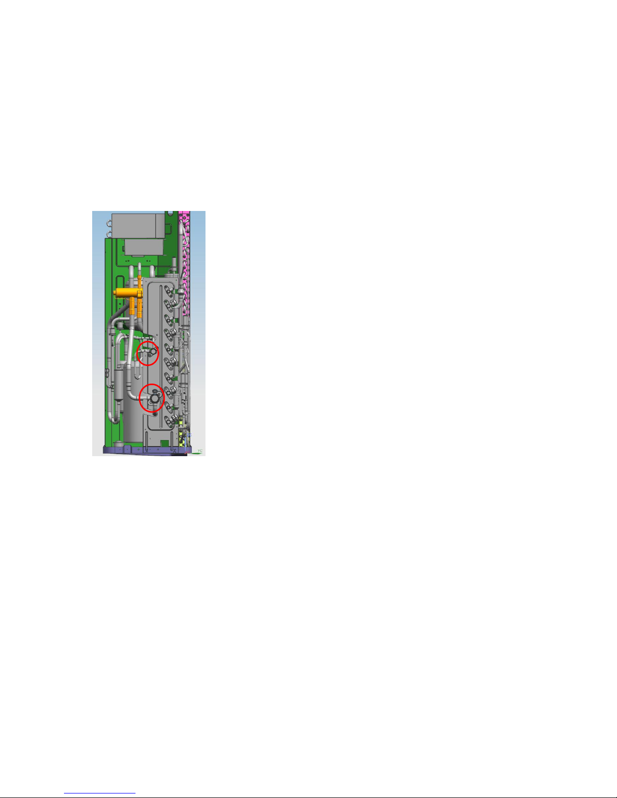
8.3 Outdoor Unit Display
8.3.1 Outdoor Unit Point Check Function
A check switch is included on the outdoor PCB.
Push SW1 to check the unit's status while running. The digital display shows the following
codes each time the SW1 is pushed.
Page 38

38
Number
of
Presses
Display Remark
0 Normal display
Displays running frequency, running state, or malfunction
code
1 Quantity of indoor units with working
connection
Actual data
Display Number of indoor unit
1 1
2 2
3 3
4 4
2 Outdoor unit running mode code Off: 0,Fan only: 1, Cooling: 2, Heating: 3, Forced cooling: 4.
Forced defrost:A
3 Indoor unit A capacity
The capacity unit is horse power. If the indoor unit is not
connected, the digital display shows the following: “――”
(9K:1HP,12K:1.2HP,18K:1.5HP)
4 Indoor unit B capacity
5 Indoor unit C capacity
6 Indoor unit D capacity
7 Indoor unit E capacity
8 Indoor unit A capacity demand code
Norm code*HP
(9K: 1HP,12K: 1.2HP,18K: 1.5HP)
9 Indoor unit B capacity demand code
10 Indoor unit C capacity demand code
Page 39

39
11 Indoor unit D capacity demand code
12 Indoor unit E capacity demand code
13 Outdoor unit amendatory capacity demand
code
14 The frequency corresponding to the total
indoor units' amendatory capacity demand
15 The frequency after the frequency limit
16 The frequency sending to compressor
control chip
17 Indoor unit A evaporator outlet temperature
(T2BA)
If the temperature is lower than -9 ℃, the digital display shows “-
9.” If the temperature is higher than 70 ℃, the digital display
shows “70.” If the indoor unit is not connected, the digital display
shows: “――”
18 Indoor unit B evaporator outlet temperature
(T2BB)
19 Indoor unit C evaporator outlet temperature
(T2BC)
20 Indoor unit D evaporator outlet temperature
(T2BD)
21 Indoor unit E evaporator outlet temperature
(T2BE)
22 Indoor unit A room temperature (T1A)
If the temperature is lower than 0 ℃, the digital display shows “0.”
If the temperature is higher than 50 ℃, the digital display shows
“50.” If the indoor unit is not connected, the digital display shows:
“――”
23 Indoor unit B room temperature (T1B)
24 Indoor unit C room temperature (T1C)
25 Indoor unit D room temperature (T1D)
26 Indoor unit E room temperature (T1E)
27 Indoor unit A evaporator temperature (T2A)
If the temperature is lower than -9 ℃, the digital display shows “-
9.” If the temperature is higher than 70 ℃, the digital display
shows “70.” If the indoor unit is not connected, the digital display
shows: “――”
28 Indoor unit B evaporator temperature (T2B)
29 Indoor unit C evaporator temperature (T2C)
30 Indoor unit D evaporator temperature (T2D)
31 Indoor unit E evaporator temperature (T2E)
32 Condenser pipe temperature (T3)
33 Outdoor ambient temperature (T4)
34 Compressor discharge temperature (TP)
The display value is between 30–129 ℃. If the temperature is
lower than 30 ℃, the digital display shows “30.” If the temperature
is higher than 99 ℃, the digital display shows single and double
digits. For example, if the digital display shows “0.5", the
compressor discharge temperature is 105 ℃.
35 AD value of current
The display value is a hex number.
For example, the digital display tube shows “Cd”, it means AD
value is 205.
36 AD value of voltage
37 EXV open angle for A indoor unit
Actual data/4.
If the value is higher than 99, the digital display shows single and
double digits.
For example, if the digital display shows “2.0", the EXV open
angle is 120×4=480p.
38 EXV open angle for B indoor unit
39 EXV open angle for C indoor unit
40 EXV open angle for D indoor unit
41 EXV open angle for E indoor unit
42 Frequency limit symbol
Bit7
Frequency limit caused by IGBT
radiator
The display
value is a
hexidecimal
number. For
example, the
digital display
show 2A, then
Bit6
Frequency limit caused by PFC
Bit5
Frequency limit caused by T4.
Bit4
Frequency limit caused by T2.
Bit3
Frequency limit caused by T3.
Page 40

40
Bit2
Frequency limit caused by T5.
Bit5=1, Bit3=1,
and Bit1=1.
This means
that a
frequency limit
may be caused
by T4, T3, or
the current.
Bit1
Frequency limit caused by current
Bit0
Frequency limit caused by voltage
43 Average value of T2 (Sum T2 value of all indoor units)/(number of indoor units in good
connection)
44 Outdoor unit fan motor state Off: 0, High speed:1, Med speed: 2, Low speed: 3, Breeze:4,
Super breeze: 5
45 The last error or protection code 00 means no malfunction and protection
46 F indoor unit capacity
47 F indoor unit capacity demand code
48 F indoor unit evaporator outlet temperature
(T2BF)
49 F indoor unit room temperature (T1F)
50 F indoor unit evaporator temperature (T2F)
51 EXV open angle for F indoor unit
8.3.2 Outdoor Unit Digital Display
A digital display is featured on the outdoor PCB.
The LED displays different codes in the following situations:
Standby: “- -.”
Compressor operation: the running frequency.
Defrosting mode: “dF” or alternative displays between running frequency and
“dF” (ach appears for 0.5s.)
Compressor pre-heating: “PH” or alternative displays between running frequency
and “PH” (each appears for 0.5s.)
Oil return process: “RO” or alternative displays between running
frequency and “RO” (each appears for 0.5s.)
Low ambient cooling mode: “LC” or alternative displays between running
frequency and “LC” (each appears for 0.5s.)
Forced cooling mode: the LED displays “FC” or alternative displays between running
frequency and
“FC” (each appears for 0.5s).
PFC module protection occurs three times within 15 minutes: “E6” or
alternates between displays of running frequency and “E6” (each appears for 0.5s.)
In protection or malfunction, the LED displays an error code or protection code.
Page 41

41
8.3.3 Outdoor unit error display
Display
LED STATUS
New indoor
Error
E0 Outdoor unit EEPROM parameter error
F4
E2 Communication malfunction between indoor and outdoor units
E1
E3
Communication malfunction between IPM board and outdoor main
control board
——
E4
Outdoor temperature sensor (coil sensor T3,ambient sensor T4,
Compressor discharge sensor T5、indoor coil outlet pipe sensor T2B)
malfunction
F2/F1/F3/F6
E5 Over-voltage or under-voltage protection
P1
E6 PFC module protection
——
E8 Outdoor fan speed malfunction
F5
F1 No. A Indoor unit coil outlet temp. sensor malfunction
——
F2 No. B Indoor unit coil outlet temp. sensor malfunction
——
F3 No. C Indoor unit coil outlet temp. sensor malfunction
——
F4 No. D Indoor unit coil outlet temp. sensor malfunction
——
F5 No. E Indoor unit coil outlet temp. sensor malfunction
——
F6 No. F Indoor unit coil outlet temp. sensor malfunction
——
P1 High pressure protection
P2
P2 Low pressure protection
P2
P3 Current overload protection
F0
P4 Temperature protection of compressor discharge
——
P5 Condenser high temperature protection
——
P6 Inverter module (IPM) malfunction P0
LP Low ambient temperature protection
——
Page 42

42
8.4 Diagnosis and Solution
8.4.1 Indoor unit trouble shooting
8.4.1.1
Indoor unit EEPROM parameter error
diagnosis and solution.
Malfunction conditions
Indoor or outdoor PCB main chip does not receive feedback
from EEPROM chip.
Potential causes
●
Installation mistake
●
Faulty PCB
Trouble shooting:
Yes
Replace the indoor/outdoor
main PCB.
Power off, then restart the
unit 3 minutes later. Does
a problem still remain?
EEPROM: a type of read-only memory. The contents can be erased and reprogrammed using a pulsed
voltage. To locate the EEPROM chip,.
Page 43

43
8.4.1.2 Communication malfunction between indoor and outdoor units diagnosis and
solution.
Malfunction conditions
If indoor unit does not receive the feedback from outdoor unit
during 120 seconds.
Potential causes
● Wiring mistake
● Faulty indoor or outdoor PCB
Trouble shooting:
Page 44

44
Page 45

45
Pic 1: Use a multimeter to test the
DC voltage between 2(old: L2) port
and S port of outdoor unit. The red
pin of multimeter connects with 2
(old: L2) port while the black pin is
for S port.
When AC is normal running, the
voltage will move alternately
between positive value and
Page 46

46
Operating
Standby
Pic 2: IPM (for 2 zone/ 3-zone)
Page 47

47
PIC3: Main board LED when power on and
unit standby.
Pic 2: IPM (for5 zone)
Power
Standby
Operating
Page 48

48
8.4.1.3 Zero-crossing signal detection error diagnosis and solution.
Malfunction conditions
When PCB does not receive zero crossing signal feedback for
4 minutes or the zero crossing signal time interval is abnormal.
Potential causes
● Connection mistake
● Faulty PCB
Trouble shooting:
Check if the connections and
power supply is normal ?
Correct the connections . Turn on the
unit when the power supply is good .
No
Yes
Indoor main PCB is
defective. Replace indoor
main PCB.
PIC 4: Check point button, press 1 time for check
how many indoor units are connected.
Page 49

49
8.4.1.4 Indoor fan speed malfunction diagnosis and solution.
Malfunction conditions
When indoor fan speed is too low (300RPM) for a certain period of time,
the unit ceases operation and the LED displays a failure code.
Potential causes
●
Wiring mistake
●
Faulty fan assembly
●
Faulty fan motor
●
Faulty PCB
Trouble shooting:
Page 50

50
Index 1:
1: Indoor AC fan motor
Power on and set the unit running in fan mode at high fan speed. After running for 15 seconds,
measure the voltage of pin1 and pin2. If the value of the voltage is less than 100V (208~240V power
supply)or 50V(115V power supply), the PCB must have problems and need to be replaced.
2. Indoor DC fan motor (control chip is inside fan motor)
Power on and when the unit is in standby, measure the voltage of pin1-pin3, pin4-pin3 in fan motor
connector. If the value of the voltage is not in the range showing in below table, the PCB must have
problems and need to be replaced.
For other models:
DC motor voltage input and output
NO. Color Signal Voltage
1 Red Vs/Vm 200V~380V
2 --- --- ---
3 Black GND 0V
4 White Vcc 13.5-16.5V
5 Yellow Vsp 0~6.5V
6 Blue FG 13.5-16.5V
Page 51

51
8.4.1.5 Temperature sensor malfunction diagnosis and solution.
Malfunction conditions
If the sampling voltage is lower than 0.06V or higher than 4.94V,
the LED displays a failure.
Potential causes
●
Wiring mistake
●
Faulty sensor
●
Faulty PCB
Trouble shooting:
Check the connections
between temperature
sensor and PCB. Are
the connections good?
Correct the connections.No
Yes
Yes Replace indoor or outdoor PCB.
Replace the sensor
Check the resistance value
of the sensor via Appendix 1
and Appendix 2
Is it normal?
No
Page 52

52
8.4.1.6 Inverter module (IPM) malfunction diagnosis and solution.
Malfunction conditions
When the voltage signal that IPM send to compressor drive
chip is abnormal, the display LED will show “P6” and AC will
turn off.
Potential causes
● Wiring mistake
● IPM malfunction
● Faulty outdoor fan assembly
● Compressor malfunction
● Faulty outdoor PCB
Trouble shooting:
Page 53

53
IPM module protection
Check whether the voltage range
of P-N on IPM module is normal?
DC277-356V for 18-27KBtu/h;
DC277-410V for 36K-48KBtu/h
Yes
Yes
No
Yes
Check whether the input
power supply is correct?
208-230V, 1N, 60Hz
No No
Regulate it to correct, then
check whether the system
can work normally?
Check whether the
power supply line is
connected correctly and
tightly
Yes
Connect it correctly
and tightly, check ok
or not?
No
Check whether the connecting
line between main board and
the IPM module is connected
tightly
Yes
Connect it tightly,
check ok or not?
No
No
No
Connect it well, check
ok or not?
Check whether the connecting
line of the compressor is
connected correctly or tightly
Replace the IPM module,
check whether the system can
work normally?
No
No
Replace the main board; check
whether the system can work
normally?
No
Replace the compressor, check
whether the system can work
normally?
Check whether the lines
in E-part box are
connected tightly
Yes
Connect it tightly,
check ok or not?
No
No
Yes
No
Replace the bridge rectifiers
Check whether the bridge rectifiers are
normal? Use the multimeter to measure
the resistance between each two
terminals, check whether there is the
condition that value of resistance is 0
Check whether the connecting line of
every reactor is normal? If the line is
broken, the resistance of the two ports is
∞;Check whether the PFC module
broken .
Replace the connecting line or
reactor or replace the PFC module
Yes
No
No
Yes
Trouble is solved
Check if the outdoor fan
runs properly or the outdoor
unit ventilation is good.
No
For AC fan models, please refer
to 9.4 Trouble Criterion Of Main
Parts, check whether the
resistance of the fan motor is
normal. If not, replace the fan
motor.
For DC fan models, r
efer to
the solution of fan speed has
been out of control malfunction
. Find out the cause and have it
solved.
Yes
Yes
Yes
Page 54

54
8.4.1.7 Over-voltage or under-voltage protection diagnosis and solution.
Page 55

55
8.4.1.8 Compressor drive malfunction diagnosis and solution
The trouble shooting is same with one of IPM module protection.
8.4.1.9
Water-level alarm malfunction
diagnosis and solution
Malfunction conditions
If the sampling voltage is not 5V, the LED will display the failure code.
Potential causes
● Wiring mistakes
● Faulty water-level switch
● Faulty water pump
● Faulty indoor PCB
Page 56

56
8.4.1.10 Indoor units mode conflict
Error Code
P5(old model) or - -(new model)
Malfunction conditions
The indoor units cannot work cooling mode and heating at same time.
Heating mode has a priority.
Potential causes
● Suppose Indoor unit A working in cooling mode or fan mode, and
indoor unit B is set to heating mode, then A will change to off and
B will work in heating mode.
● Suppose Indoor unit A working in heating mode, and indoor unit
B is set to cooling mode or fan mode, then B will change to stand
by and A will be no change.
Cooling mode Heating Mode Fan Off
Cooling mode No Yes No No
Heating Mode Yes No Yes No
Fan No Yes No No
Off No No No No
No: No mode conflict;
Yes: Mode conflict
Page 57

57
8.4.2 Outdoor unit trouble shooting
8.4.2.1 E0 (Outdoor unit EEPROM parameter error) diagnosis and solution
Error Code
E0
Malfunction
PCB main chip does not receive feedback from EEPROM chip
Potential causes
● Installation mistake
●
Faulty PCB
Trouble shooting:
Yes
Replace the outdoor main
PCB
Replace the outdoor main
PCB
Power off, then restart the
unit 3 minutes later
Power off, then restart the
unit 3 minutes later
Outdoor EEPROM malfunction
Outdoor EEPROM malfunction
EEPROM: a type of read-only memory. The contents can be erased and reprogrammed using a pulsed
voltage.
refer to the following photos.
Page 58

58
8.4.2.2 E2(Communication malfunction between indoor and outdoor units) diagnosis and solution.
Error Code
E2
Malfunction
conditions
Indoor unit does not receive the feedback from outdoor unit
during 120 seconds or outdoor unit does not receive the
feedback from any one indoor unit during 180 seconds.
Potential causes
● Wiring mistake
● Faulty Indoor or outdoor PCB
Trouble shooting:
Page 59

59
Page 60

60
Pic 1: Use a multimeter to test the
DC voltage between 2(old: L2) port
and 3 port of outdoor unit. The red
pin of multimeter connects with 2
(old: L2) port while the black pin is
for 3 port.
When AC is normal running, the
voltage will move alternately
between positive value and
Page 61

61
Operating
Standby
Pic 2: IPM board (for 2 zone/ 3-zone)
Page 62

62
PIC3: Main board LED when power on and
unit standby.
Pic 2: IPM (for5 zone)
Power
Standby
Operating
Page 63

63
8.4.2.3 E3 (Communication malfunction between IPM board and outdoor main control board)
diagnosis
Error Code
E3
Malfunction
conditions
PCB main chip does not receive feedback from IPM module
during 60 seconds.
Potential causes
● Wiring mistake
● Faulty PCB
Trouble shooting:
PIC 4: Check point button, press 1 time for check
how many indoor units are connected.
Page 64

64
Page 65

65
Remark:
Use a multimeter to test the DC
voltage between black pin and
white pin of signal wire The normal
value should be around 5V.
Use a multimeter to test the DC
voltage between black pin and red
pin of signal wire. The normal value
should be around 12V.
Page 66

66
8.4.2.4 E4 (Outdoor temperature sensor (coil sensor T3,ambient sensor T4, Compressor discharge
sensor T5、indoor coil outlet pipe sensor T2B) malfunction) diagnosis and solution
F1/F2/F3/F4/F5 (No.A,B,C,D,E Indoor unit coil outlet temp. sensor malfunction) diagnosis and
solution.
.
Error Code
E4/F1/F2/F3/F4/F5
Malfunction
conditions
If the sampling voltage is lower than 0.06V or higher than
4.94V, the LED will display the failure.
Potential causes
● Wiring mistake
● Faulty sensor
● Faulty PCB
Trouble shooting:
Page 67

67
8.4.2.5 E5 (Over-voltage or under-voltage protection) diagnosis and solution.
Error Code
E5
Malfunction conditions
An abnormal voltage rise or drop is detected by checking the
specified voltage detection circuit.
Potential causes
● Power supply problems.
● System leakage or block
● Faulty PCB
Trouble shooting:
Voltage protection
Check the voltage of
outdoor unit power supply,
whether the voltage
between L(L1) and N (L2) is
about 187~264VAC
Check the power supply
Check whether the voltage of IPM
board P and N(GND) is normal?
DC277—356V for 2-zone(18K Btu/h)/3
zone(27K Btu/h)
DC277-410V For 4-zone(36K Btu/h)/5-
zone(48K Btu/h)
Replace bridge rectifiers,
and then check whether the
system can run normally
(for
5-zone)
Replace IPM board, and
then check whether the
system can run normally
Replace outdoor main board
Yes
No
No
No
No
Yes
Trouble is solved
Yes
Yes
Page 68

68
IPM board (for
2-zone /3-zone)
Page 69

69
P(or E1/E2/E3)-N(GND)
(for 2-zone/3-zone)
Bridge rectifier
(for 2-zone/3-zone)
Bridge rectifier
(for 2-zone/3-zone)
IPM Module
(for 2-zone/3-zone)
Remark:
Measure the DC voltage
between + and - port. The
normal value should be
190V~250V.
Page 70

70
IPM board
(for 4-zone)
Page 71

71
IPM board
(for 5-zone)
Bridge rectifier
(for 5-zone)
Remark:
Measure the DC voltage
between + and - port. The
normal value should be
190V~250V.
IPM Module
(for 5-zone)
Page 72

72
8.4.2.6 E6 (PFC module protection) error diagnosis and solution.
Error Code
E6
Malfunction
conditions
When the voltage signal that PFC sends to main control board
is abnormal, the display LED will show “E6” and AC will turn
off.
Potential causes
● Wiring mistake
● Faulty outdoor PCB
● Faulty inductance of PFC module
●
PFC module malfunction
Trouble shooting:
Page 73

73
Two ports of the inductance
Inductance
Page 74

74
8.4.2.7 E8 (Outdoor fan speed malfunction) diagnosis and solution
Error Code
E8
Malfunction conditions
When outdoor fan speed keeps too low (300RPM) or too
high(2400RPM) for certain time, the unit will stop and the LED will
display the failure.
Potential causes
● Wiring mistake
● Faulty Fan assembly
● Faulty Fan motor
●
Faulty PCB
Trouble shooting:
Page 75

75
Index 1:
1. DC fan motor(control chip is inside fan motor)
Power on and when the unit is in standby, measure the voltage of pin1-pin3, pin4-pin3 in fan motor
connector. If the value of the voltage is not in the range showing in below table, the PCB must have
problems and need to be replaced.
DC motor voltage input and output
NO.
Color
Signal
Voltage
1 Red Vs/Vm 200~380V
2 --- --- ---
3 Black GND 0V
4 White Vcc 13.5~16.5V
5 Yellow Vsp 0~6.5V
6 Blue FG 13.5~16.5V
Page 76

76
Vs Vcc
Vsp FG
Page 77

77
8.4.2.8 P1 (High pressure protection) diagnosis and solution.
Error Code
P1
Malfunction conditions
If the sampling voltage is not 5V, the LED will display the
failure.
Potential causes
● Wiring mistake
● Faulty over load protector
● System block
● Faulty outdoor PCB
Trouble shooting:
Page 78

78
Page 79

79
Page 80

80
8.4.2.9 P2 (Low pressure protection) diagnosis and solution.
Error Code
P2
Malfunction conditions
If the sampling voltage is not 5V, the LED will display the
failure.
Potential causes
● Wiring mistake
● Faulty over load protector
● System block
● Faulty outdoor PCB
Trouble shooting:
Page 81

81
Page 82

82
Page 83

83
8.4.2.10 P3 (Current overload protection) diagnosis and solution.
Error Code
P3
Malfunction conditions
If the outdoor current exceeds the current limit value, the LED
will display the failure.
Potential causes
● Wiring mistake
● Faulty over load protector
● System block
● Faulty outdoor PCB
Trouble shooting:
Page 84

84
Page 85

85
Page 86

86
8.4.2.11 P4 (Temperature protection of compressor discharge) diagnosis and solution.
Error Code
P4
Malfunction conditions
When the compressor discharge temperature(T5) is more
than 115℃ for 10 seconds, the compressor will stop
and
restart till T5 is less than 90℃.
Potential causes
● Refrigerant leakage
● Wiring mistake
● Faulty discharge temperature sensor
● Faulty outdoor PCB
Trouble shooting:
Page 87

87
Page 88

88
8.4.2.12 P5 (High temperature protection of condenser) diagnosis and solution.
Error Code
P5
Malfunction conditions
When outdoor pipe temperature is more than 65°C, the unit will
stop, and unit runs again when outdoor pipe temperature is less
than 52°C
Potential causes
● Faulty condenser temperature sensor
● Heat exchanger dirty
● System block
Trouble shooting:
Page 89

89
8.4.2.13 P6 (Inverter module (IPM) malfunction) diagnosis and solution.
Error Code
P6
Malfunction conditions
When the voltage signal that IPM send to compressor drive
chip is abnormal, the display LED will show “P6” and AC will
turn off.
Potential causes
● Wiring mistake
● IPM malfunction
● Faulty outdoor fan assembly
● Compressor malfunction
● Faulty outdoor PCB
Trouble shooting:
Page 90

90
IPM module protection
Check whether the voltage range
of P-N on IPM module is normal?
DC277-356V for 18-27KBtu/h;
DC277-410V for 36KBtu/h
Yes
Yes
No
Yes
Check whether the input
power supply is correct?
208-230V, 1N, 60Hz
No No
Regulate it to correct, then
check whether the system
can work normally?
Check whether the
power supply line is
connected correctly and
tightly
Yes
Connect it correctly
and tightly, check ok
or not?
No
Check whether the connecting
line between main board and
the IPM module is connected
tightly
Yes
Connect it tightly,
check ok or not?
No
No
No
Connect it well, check
ok or not?
Check whether the connecting
line of the compressor is
connected correctly or tightly
Replace the IPM module,
check whether the system can
work normally?
No
No
Replace the main board; check
whether the system can work
normally?
No
Replace the compressor, check
whether the system can work
normally?
Check whether the lines
in E-part box are
connected tightly
Yes
Connect it tightly,
check ok or not?
No
No
Yes
No
Replace the bridge rectifiers
Check whether the bridge rectifiers are
normal? Use the multimeter to measure
the resistance between each two
terminals, check whether there is the
condition that value of resistance is 0
Check whether the connecting line of
every reactor is normal? If the line is
broken, the resistance of the two ports is
∞(models except for M4OC-36HRFN1M);Check whether the PFC module
broken (for M4OC-36HRFN1-M)
Replace the connecting line or
reactor or replace the PFC
module(for M4OC-36HRFN1-M)
Yes
No
No
Yes
Trouble is solved
Check if the outdoor fan
runs properly or the outdoor
unit ventilation is good.
No
For M3OD-27HRDN1-M, please
refer to 8.5 Trouble Criterion Of
Main Parts, check whether the
resistance of the fan motor is
normal. If not, replace the fan
motor.
For other models, r
efer to
the solution of fan speed has
been out of control
malfunction . Find out the cause
and have it solved.
Yes
Yes
Yes
Page 91

91
8.4.
2.14 The cooling operation or heating operation does not operate.
Potential causes
● Faulty 4-way valve
Check of 4-way, please refer to part 5 in
9.5 Trouble Criterion Of Main Parts.
8.4.2.15 When cooling, heat exchanger of non-operating indoor unit frosts.
When heating, non-operating indoor unit get warm.
Potential causes
● Faulty EXV
● Wire and tubing connected in reverse.
Check of EXV, please refer to part 6 in
9.5 Trouble Criterion Of Main Parts.
8.5 Trouble Criterion Of Main Parts.
Spec.
Indoor unit
Model 9k Oasis 12k Oasis 18k Oasis 24k Oasis
Indoor fan motor
WZDK20-38G WZDK20-38G WZDK58-38G WZDK60-38G
Model
MEHSU-09CHD2 MEHSU-12CHD2 MEHSU-18CHD2 MEHSU-24CHD2
Indoor fan motor
WZDK55-38GS-W WZDK55-38GS-W WZDK90-38GS-W WZDK90-38GS-W
Model
MEHSU-09CHC2 MEHSU-12CHC2 MEHSU-18CHC2 MEHSU-24CHC2
Indoor fan motor
WZDK46-38G WZDK46-38G WZDK46-38G ZKFP-42-8-1
Model
MEHSU-09CHN2 MEHSU-12CHN2 MEHSU-18CHF2 MEHSU-24CHF2
Indoor fan motor
RD-280-20-8A RD-280-20-8A ZKFN-55-8-1 ZKFN-55-8-1
Outdoor unit
Model MCH2U-18PHH2 MCH3U-27PHH2 MCH4U-36PHH2 MCH5U-48PHH2
Compressor
ATM150D23UFZ ATF235D22UMT ATF310D43UMT ATQ360D1UMU
Outdoor fan motor
ZKFN-50-8-2 ZKFN-120-8-2 ZKFN-120-8-2 ZKFN-85-8-22
Page 92

92
1.
1.Temperature sensor checking
Disconnect the temperature sensor from PCB, measure the resistance value with a tester.
Temperature Sensors.
Room temp.(T1) sensor,
Indoor coil temp.(T2) sensor,
Outdoor coil temp.(T3) sensor,
Outdoor ambient temp.(T4) sensor,
Compressor discharge temp.(T5) sensor.
Measure the resistance value of each winding by using the multi-meter.
Page 93

93
Appendix 1 Temperature Sensor Resistance Value Table (℃--K)
℃
K Ohm
℃
K Ohm
℃
K Ohm
℃
K Ohm
-20
115.266
20 12.6431 60 2.35774 100 0.62973
-19 108.146 21 12.0561 61 2.27249 101 0.61148
-18 101.517 22 11.5000 62 2.19073 102 0.59386
-17 96.3423 23 10.9731 63 2.11241 103 0.57683
-16 89.5865 24 10.4736 64 2.03732 104 0.56038
-15 84.2190 25 10.000 65 1.96532 105 0.54448
-14 79.3110 26 9.55074 66 1.89627 106 0.52912
-13 74.5360 27 9.12445 67 1.83003 107 0.51426
-12 70.1698 28 8.71983 68 1.76647 108 0.49989
-11 66.0898 29 8.33566 69 1.70547 109 0.48600
-10 62.2756 30 7.97078 70 1.64691 110 0.47256
-9 58.7079 31 7.62411 71 1.59068 111 0.45957
-8 56.3694 32 7.29464 72 1.53668 112 0.44699
-7 52.2438 33 6.98142 73 1.48481 113 0.43482
-6 49.3161 34 6.68355 74 1.43498 114 0.42304
-5 46.5725 35 6.40021 75 1.38703 115 0.41164
-4 44.0000 36 6.13059 76 1.34105 116 0.40060
-3 41.5878 37 5.87359 77 1.29078 117 0.38991
-2 39.8239 38 5.62961 78 1.25423 118 0.37956
-1 37.1988 39 5.39689 79 1.21330 119 0.36954
0 35.2024 40 5.17519 80 1.17393 120 0.35982
1 33.3269 41 4.96392 81 1.13604 121 0.35042
2 31.5635 42 4.76253 82 1.09958 122 0.3413
3 29.9058 43 4.57050 83 1.06448 123 0.33246
4 28.3459 44 4.38736 84 1.03069 124 0.32390
5 26.8778 45 4.21263 85 0.99815 125 0.31559
6 25.4954 46 4.04589 86 0.96681 126 0.30754
7 24.1932 47 3.88673 87 0.93662 127 0.29974
8 22.5662 48 3.73476 88 0.90753 128 0.29216
9 21.8094 49 3.58962 89 0.87950 129 0.28482
10 20.7184 50 3.45097 90 0.85248 130 0.27770
11 19.6891 51 3.31847 91 0.82643 131 0.27078
12 18.7177 52 3.19183 92 0.80132 132 0.26408
13 17.8005 53 3.07075 93 0.77709 133 0.25757
14 16.9341 54 2.95896 94 0.75373 134 0.25125
15 16.1156 55 2.84421 95 0.73119 135 0.24512
16 15.3418 56 2.73823 96 0.70944 136 0.23916
17 14.6181 57 2.63682 97 0.68844 137 0.23338
18 13.9180 58 2.53973 98 0.66818 138 0.22776
19 13.2631 59 2.44677 99 0.64862 139 0.22231
Page 94

94
Appendix 2
Unit: ℃---K Discharge temp. sensor table
-20 542.7 20 68.66 60 13.59 100 3.702
-19 511.9 21 65.62 61 13.11 101 3.595
-18 483 22 62.73 62 12.65 102 3.492
-17 455.9 23 59.98 63 12.21 103 3.392
-16 430.5 24 57.37 64 11.79 104 3.296
-15 406.7 25 54.89 65 11.38 105 3.203
-14 384.3 26 52.53 66 10.99 106 3.113
-13 363.3 27 50.28 67 10.61 107 3.025
-12 343.6 28 48.14 68 10.25 108 2.941
-11 325.1 29 46.11 69 9.902 109 2.86
-10 307.7 30 44.17 70 9.569 110 2.781
-9 291.3 31 42.33 71 9.248 111 2.704
-8 275.9 32 40.57 72 8.94 112 2.63
-7 261.4 33 38.89 73 8.643 113 2.559
-6 247.8 34 37.3 74 8.358 114 2.489
-5 234.9 35 35.78 75 8.084 115 2.422
-4 222.8 36 34.32 76 7.82 116 2.357
-3 211.4 37 32.94 77 7.566 117 2.294
-2 200.7 38 31.62 78 7.321 118 2.233
-1 190.5 39 30.36 79 7.086 119 2.174
0 180.9 40 29.15 80 6.859 120 2.117
1 171.9 41 28 81 6.641 121 2.061
2 163.3 42 26.9 82 6.43 122 2.007
3 155.2 43 25.86 83 6.228 123 1.955
4 147.6 44 24.85 84 6.033 124 1.905
5 140.4 45 23.89 85 5.844 125 1.856
6 133.5 46 22.89 86 5.663 126 1.808
7 127.1 47 22.1 87 5.488 127 1.762
8 121 48 21.26 88 5.32 128 1.717
9 115.2 49 20.46 89 5.157 129 1.674
10 109.8 50 19.69 90 5 130 1.632
11 104.6 51 18.96 91 4.849
12 99.69 52 18.26 92 4.703
13 95.05 53 17.58 93 4.562
14 90.66 54 16.94 94 4.426
15 86.49 55 16.32 95 4.294 B(25/50)=3950K
16 82.54 56 15.73 96 4.167
17 78.79 57 15.16 97 4.045
R(90℃)=5KΩ±3%
18 75.24 58 14.62 98 3.927
19 71.86 59 14.09 99 3.812
Page 95

95
Appendix 3:
℃
10 11 12 13 14 15 16 17 18 19 20 21 22
℉
48 50 52 54 56 58 60 62 64 66 68 70 72
℃
23 24 25 26 27 28 29 30 31 32 33 34 35
℉
74 76 78 80 82 84 86 88 90 92 94 96 98
2. Compressor check
Measure the resistance value of each winding by using the tester.
Position Resistance Value
ATM150D23UFZ ATF235D22UMT ATF250D22UMT
ATF310D43UMT ATQ360D1UMU ATQ420D1UMU
Blue - Red
1.72 Ω 0.75 Ω
0.75 Ω
0.65 Ω
0.37 Ω
0.38Ω
Page 96

96
3. IPM continuity check
Turn off the power, let the large capacity electrolytic capacitors discharge completely, and dismount
the IPM. Use a digital tester to measure the resistance between P and UVWN; UVW and N.
Digital tester
Normal resistance
value
Digital tester
Normal
resistance
value
(+)Red (-)Black
∞
(Several MΩ)
(+)Red (-)Black
∞
(Several MΩ)
P
N U
N
U V
V
W
W
(+)Red
4. AC Fan Motor.
Measure the resistance value of each winding by using the tester.
Position
Resistance Value
RPG20B RPG28H
Black - Red
381Ω±8% (20℃)
(Brand: Weiling)
342Ω±8% (20℃)
(Brand: Dayang)
183.6Ω±8% (20℃)
(Brand: Weiling)
180Ω±8% (20℃)
(Brand: Wolong)
White - Black
267Ω±8% (20℃)
(Brand: Weiling)
253Ω±8% (20℃)
(Brand: Dayang)
206Ω±8% (20℃)
(Brand: Weiling)
190Ω±8% (20℃)
(Brand: Wolong)
Measure the resistance value of each winding by using the tester.
Page 97

97
Position
Resistance Value
YDK70-
6FB
YDK180-8GB YSK27-4G YSK68-4B YDK45-6B YSK25-6L
YDK53-
6FB(B)
Black -
Red
56Ω±8%
(20℃)
24.5Ω±8%
(20℃)
317Ω±8%
(20℃)
145Ω±8%
(20℃)
345Ω±8%
(20℃)
627Ω±8%
(20℃)
88.5Ω±8%
(20℃)
Red -
Yellow
76Ω±8%
(20℃)
19Ω±8%
(20℃)
252Ω±8%
(20℃)
88Ω±8%
(20℃)
150Ω±8%
(20℃)
374.3Ω±8%
(20℃)
138Ω±8%
(20℃)
Yellow -
Blue
76Ω±8%
(20℃)
19Ω±8%
(20℃)
252Ω±8%
(20℃)
88Ω±8%
(20℃)
150Ω±8%
(20℃)
374.3Ω±8%
(20℃)
138Ω±8%
(20℃)
5.4-way valve
1. Power on, use a digital tester to measure the voltage, when the unit operates in cooling, it is 0V. When
the unit operates in heating, it is about 230VAC.
If the value of the voltage is not in the range, the PCB must have problems and need to be replaced.
2 Turn off the power, use a digital tester to measure the resistance. The value should be 1.8~2.5 KΩ.
Page 98

98
6.EXV check
Disconnect the connectors.
Page 99

99
Resistance to EXV coil
Color of lead wire
Normal Value
Red- Blue
About 50Ω
Red - Yellow
Brown-Orange
Brown-White
Page 100

100
Red- Blue
Red - Yellow
 Loading...