

Page 1

DC INVERTER SERIES
Service Manual 2013
LIS-B-1306
Page 2

Page 3

Contents
Contents i
Part 1 General Information ............................................................................................. 1
Part 2 Indoor Units .......................................................................................................... 8
Part 3 Outdoor Units ................................................................................................... 116
Part 4 Installation ........................................................................................................ 133
Part 5 Electrical Control System ............................................................................... 177
※The specifications, designs, and information in this book are subject to change without notice for
product improvement.
Page 4

Page 5

General Information
General Information 1
Part 1
General Information
1. Model Lists ................................................................................................... 2
2. External Appearance ................................................................................... 4
2.1 Indoor Units .......................................................................................... 4
2.2 Outdoor Units ....................................................................................... 5
3. Nomenclature ............................................................................................... 6
4. Features ........................................................................................................ 7
Page 6
Model Lists
2 General Information
1. Model Lists
1.1 Indoor Units
R410A Capacity multiplied by 1000Btu/h
Type Function 12 18 24 30 36 48 60
New Four-way cassette
(
compact)
Cooling and heating
● ●
Four-way cassette Cooling and heating
● ● ● ●
●
Super-slim Four-way cassette Cooling and heating
● ● ● ● ●
Ceiling & floor Cooling and heating
● ● ● ● ● ● ●
3rd generation ceiling & floor Cooling and heating
● ● ●
Duct Cooling and heating
● ● ● ● ● ● ●
Console
Cooling and heating
● ●
High static pressure duct Cooling and heating
● ● ●
GA floor standing
Cooling and heating
● ● ●
1.2 Outdoor Units
Universal Outdoor unit Model Compressor type Compressor Brand Matched indoor units
MOU-12HDN1-Q Rotary DC Inverter GMCC
MCA2-12HRDN1-Q
MFA-12HRDN1-Q
MUB-12HRDN1-Q
MTB1-12HWDN1-Q
MOU-18HDN1-Q Scroll DC Inverter GMCC
MCA2-18HRDN1-Q
MCD-18HRDN1-Q
MFA-18HRDN1-Q
MUB-18HRDN1-Q
MTB-18HWDN1-Q
MOU-24HDN1-Q Rotary DC Inverter GMCC
MCC-24HRDN1-Q
MCD-24HRDN1-Q
MUB-24HRDN1-Q
MTB-24HWDN1-Q
MFGA-24ARDN1-QC2
MOU-30HDN1-Q Rotary DC Inverter MITSUBISHI
MCC-30HRDN1-Q
MCD-30HRDN1-Q
MUB-30HRDN1-Q
MTB-30HWDN1-Q
MOU-36HDN1-Q Rotary DC Inverter MITSUBISHI
MCC-36HRDN1-Q
MCD-36HRDN1-Q
MUB-36HRDN1-Q
MTB-36HWDN1-Q
MHD-36HRDN1-Q
MOU-36HDN1-Q Rotary DC Inverter
GUANGZHOU
MITSUBISHI
MCC-36HRDN1-Q
MCD-36HRDN1-Q
MUB-36HRDN1-Q
MTB-36HWDN1-Q
MHD-36HRDN1-Q
MUE-36HRDN1-Q
MOU-36HDN1-R Rotary DC Inverter
GUANGZHOU
MITSUBISHI
MCC-36HRDN1-Q
MCD-36HRDN1-Q
MUB-36HRDN1-Q
MTB-36HWDN1-Q
MHD-36HRDN1-Q
MUE-36HRDN1-Q
MFGA-36ARDN1-R
MOU-48HDN1-Q Rotary DC Inverter
GUANGZHOU
MITSUBISHI
MCC-48HRDN1-Q
MCD-48HRDN1-Q
MUE-48HRDN1-Q
MTB-48HWDN1-Q
MHD-48HRDN1-Q
MOU-48HDN1-R Rotary DC Inverter
GUANGZHOU
MITSUBISHI
MCC-48HRDN1-Q
MCD-48HRDN1-Q
Page 7

Model Lists
General Information 3
MUB-48HRDN1-Q
MUE-48HRDN1-Q
MTB-48HWDN1-Q
MHD-48HRDN1-Q
MFGA-48ARDN1-R
MOU-60HDN1-R Rotary DC Inverter
GUANGZHOU
MITSUBISHI
MCC-60HRDN1-R
MCD-60HRDN1-Q
MUB-60HRDN1-R
MUE-60HRDN1-Q
MTB-60HWDN1-R
MHD-60HRDN1-R
MFGA-60ARDN1-R
MOU-60HDN1-R Rotary DC Inverter GMCC MTB-60HWDN1-R
Page 8
External Appearance
4 General Information
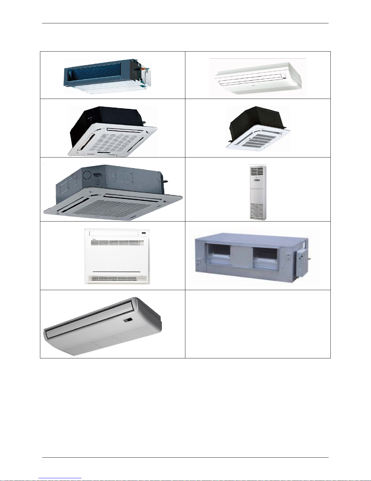
2. External Appearance
2.1 Indoor Units
Duct
Ceiling & Floor
Four-way Cassette Compact Four-way cassette
Super-slim Four-way Cassette GA Floor Standing
Console
High static pressure duct
3
r
d
generation ceiling-floor
Page 9
External Appearance
General Information 5
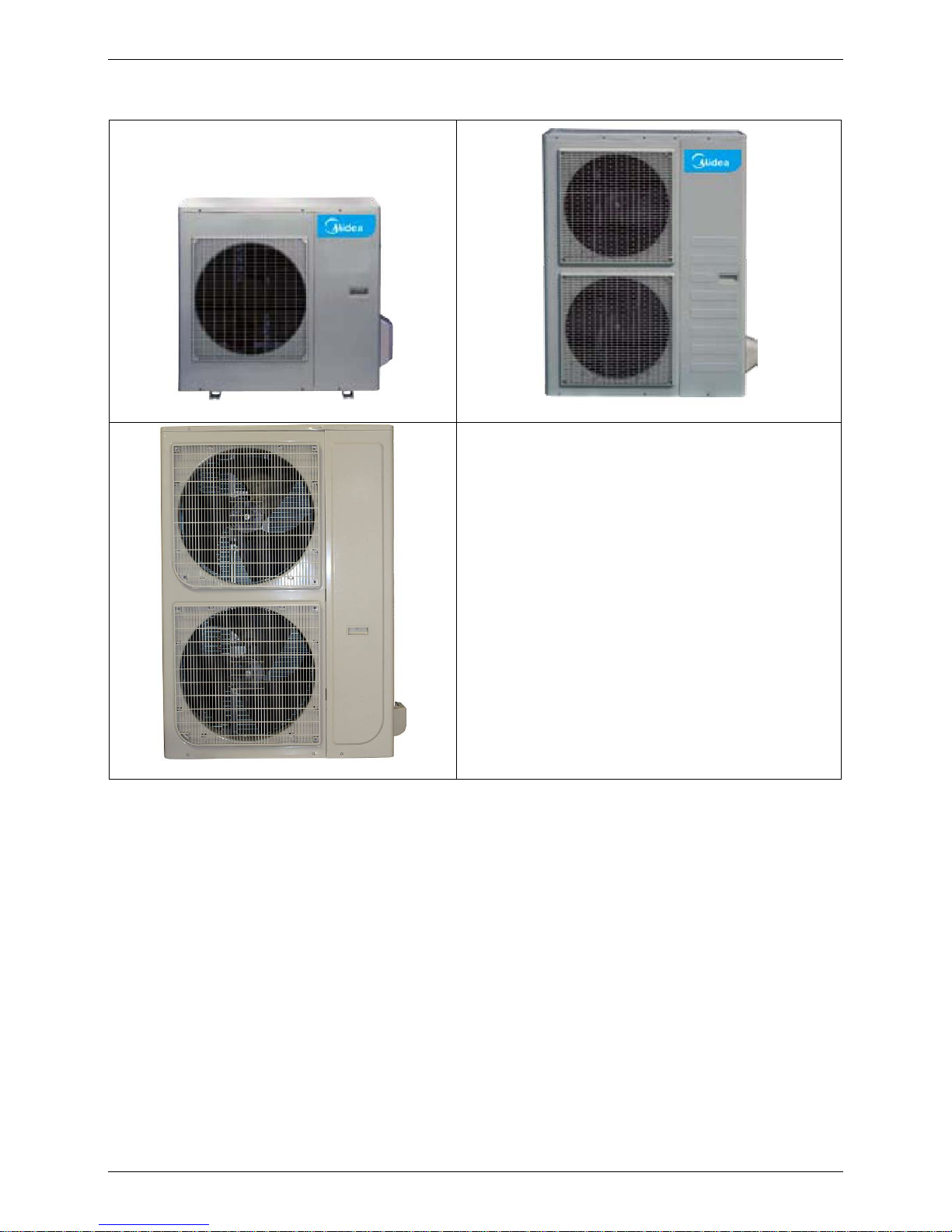
2.2 Outdoor Units
Single fan outdoor unit
Double fan outdoor unit
Double fan outdoor unit
Page 10
Nomenclature
6 General Information
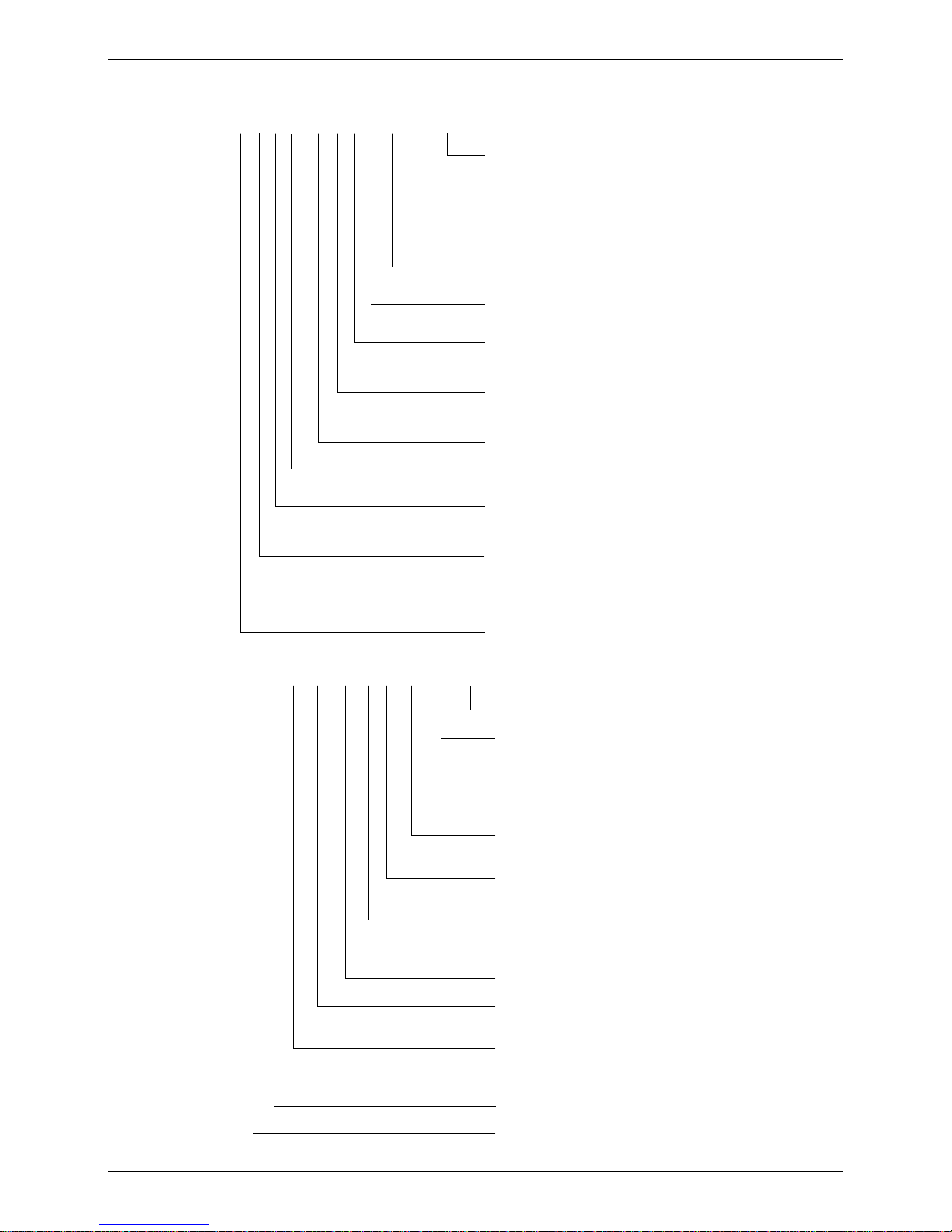
3. Nomenclature
3.1 Indoor Unit
M U B T- 36 H R D N1- Q RC4
Energy Efficiency Code
Power Supply
Q 220~240V,1N, 50Hz
R 380~420V, 3N, 50Hz
N 220~230V, 1N, 60Hz
D 220V~, 3N, 60Hz
C 380~420V,3N,60Hz
Refrigerant
N1 R410A -- R22
D DC Inverter -- On-Off
F Full DC
Control Mode
W Wired Control E Electric Control
M Mechanical Control R Remote Control
Function Code
C Cooling Only H Cooling & Heating
A Cooling & Heating+PTC
Capacity (×1000Btu/h)
T Tropical Condition
-- T1 Condition
Designed Time
A Time A Designed B Time B Designed
C Time C Designed D Time D Designed
Product Category
C Cassette Type V AHU Type
T Duct Type F Console Type
U Ceiling & Floor Type
H High Static Pressure Duct Type
Midea
3.2 Outdoor Unit
M O U T- 36 H D N1- R RC4
Energy Efficiency Code
Power Supply
Q 220~240V,1N, 50HZ
R 380~420V, 3N, 50Hz
N 220~230V, 1N, 60Hz
D 220V~, 3N, 60Hz
C 380~420v,3N,60HZ
Refrigerant
N1 R410A -- R22
D DC Inverter -- On-Off
F Full DC
Function Code
C Cooling Only H Cooling & Heating
A Cooling & Heating+PTC
Capacity (×1000Btu/h)
T Tropical Condition
-- T1 Condition
U Side Discharge Outdoor Unit
V Top Discharge Outdoor Unit
S Centrifugal Fan Outdoor Unit
O Outdoor unit
Midea
Page 11

Features
General Information 7
4. Features
4.1 Universal outdoor unit design
Indoor unit with the same capacity can match with the same outdoor unit.
4.2 High efficiency and energy saving.
Thanks to the DC inverter technology and optimized piping system, the EER and COP of whole
series can easily reach A-class.
4.3 Full range of products from 12K to 60K, including Med duct(A5), cassette, console, ceiling and floor,
more choice for you
4.4 Low ambient kit is standard for outdoor units (except 12K)
4.5 Network control function is standard for the indoor units (except 12K)
4.6 Standard auto restart function and follow me function
4.7 Cassette, ceiling & floor, console and compact cassette with standard remote controller, wire controller
and CCM for optional. Med Duct with standard wired controller, remote controller and CCM for
optional.
4.8 Standard anti-cold air function
4.9 Standard auto defrosting function
4.10 Standard self-diagnose function.
4.11 Standard timer function and sleep mode function controlled by controller.
Page 12

Indoor Units
8 Indoor Units
Part 2
Indoor Units
New Four-way Cassette Type (Compact) ............................. 9
Four-way Cassette Type ..................................................... 19
Super Slim Cassette Type .................................................. 27
Duct Type ............................................................................. 41
Ceiling & Floor Type ........................................................... 57
Console Type ....................................................................... 71
High Static Pressure Duct .................................................. 85
3rd Generation Ceiling & Floor Type .................................. 95
GA Floor-standing Type ...................................................105
Page 13

New Four-way Cassette Type (Compact)
New Four-way Cassette Type (Compact) 9
New Four-way Cassette Type (Compact)
1. Features ................................................................................................. 10
2. Dimensions ........................................................................................... 11
3. Service Space........................................................................................ 12
4. Wiring Diagrams ................................................................................... 13
5. Air Velocity and Temperature Distributions(Reference Data) .......... 14
6. Electric Characteristics ........................................................................ 15
7. Sound Levels ........................................................................................ 15
8. Accessories ........................................................................................... 16
9. The Specification of Power .................................................................. 16
10. Field Wiring ......................................................................................... 17
Page 14
Features
10
1. Features
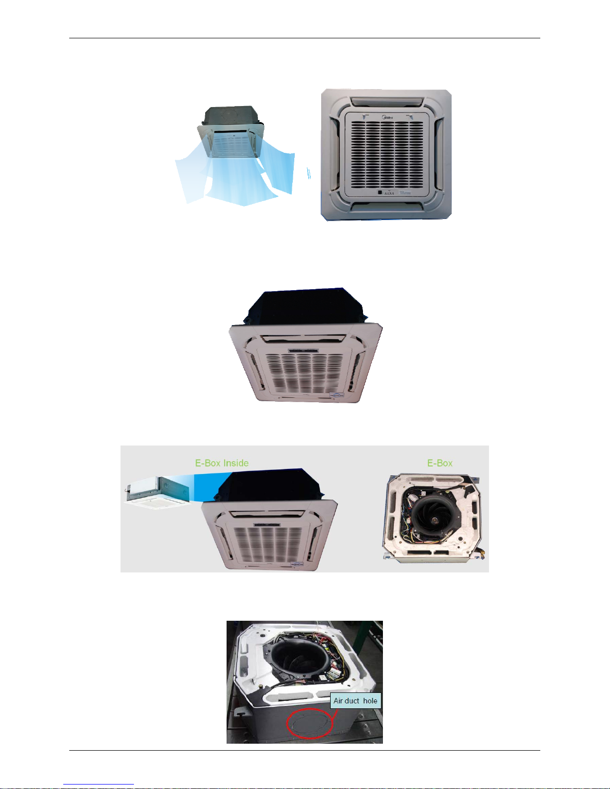
1.1 New panel
360°surrounding air outlet design, affords comfortable feeling
1.2 Compact design
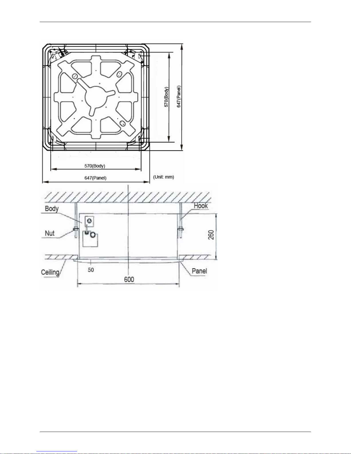
The body size is 570×260×570mm, it’s just smaller than the ceiling board, so it’s very easy for
installation and will not damage the decoration. The panel size is 647×50×647mm.
The hooks are designed in the four corners of the body, which can save installation space.
1.3 Electric control box built-in design
The E-box is simply and safely built inside the indoor unit. It’s convenient for installation and
maintenance. Can check the control part easily, you only need to open the air return grille.
1.4 Air passage function
Reserves the space for air outlet from the side of indoor unit; It’s availed to connect air duct
from the two sides to the nearby small rooms.
Page 15
Dimensions
11
2. Dimensions
Page 16
Service Space
12
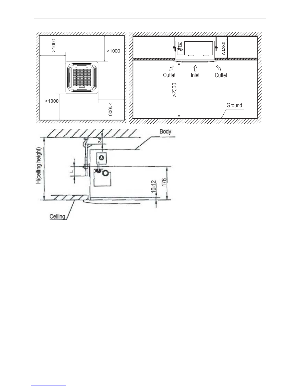
3. Service Space
Page 17
Wiring Diagrams
13
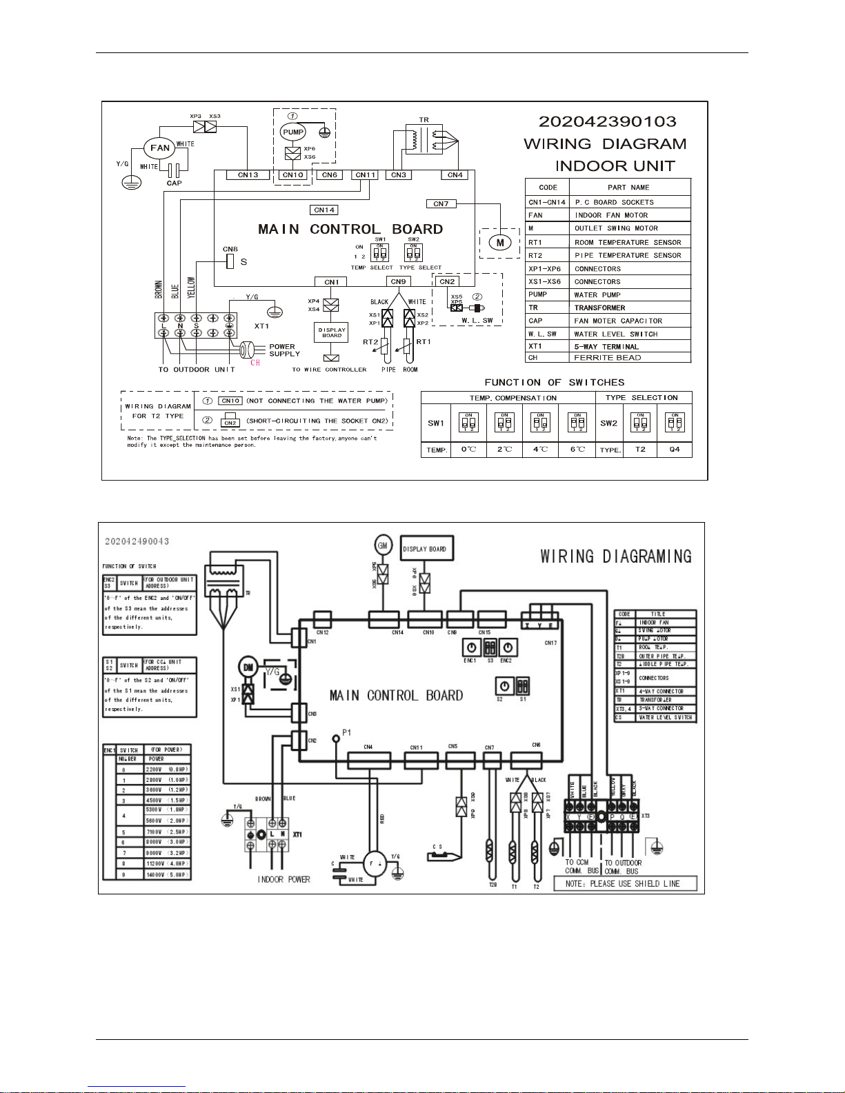
4. Wiring Diagrams
MCA2-12HRDN1-Q
MCA2-18HRDN1-Q
Page 18
Air Velocity and Temperature Distributions(Reference Data)
14
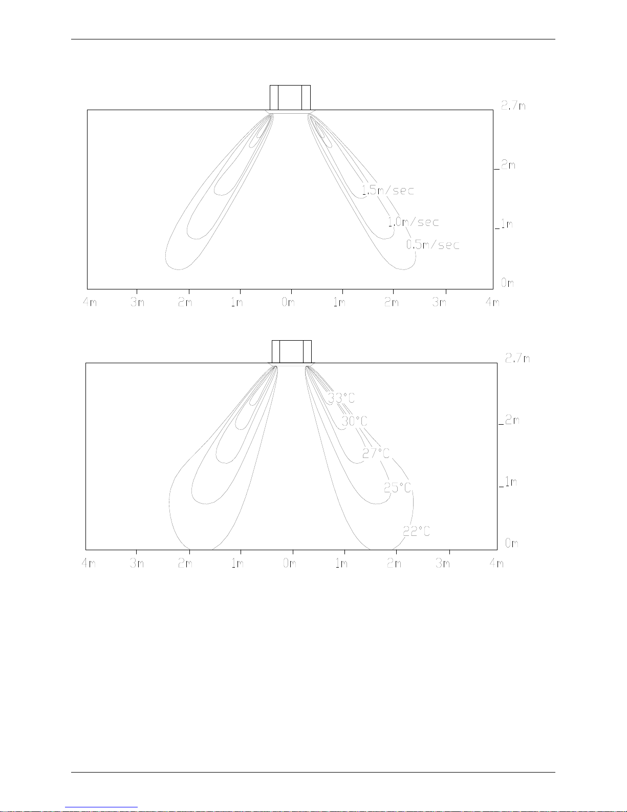
5. Air Velocity and Temperature Distributions(Reference Data)
A irflo w veloc ity
Tem perature
Page 19
Electric Characteristics
15
6. Electric Characteristics
Model
Indoor Units
Power
Supply
Hz Voltage Min. Max. MFA
MCA2-12HRDN1-Q 50 220-240V 198V 254V 20
MCA2-18HRDN1-Q 50 220-240V 198V 254V 15
Notes:
MFA: Max. Fuse Amps. (A)
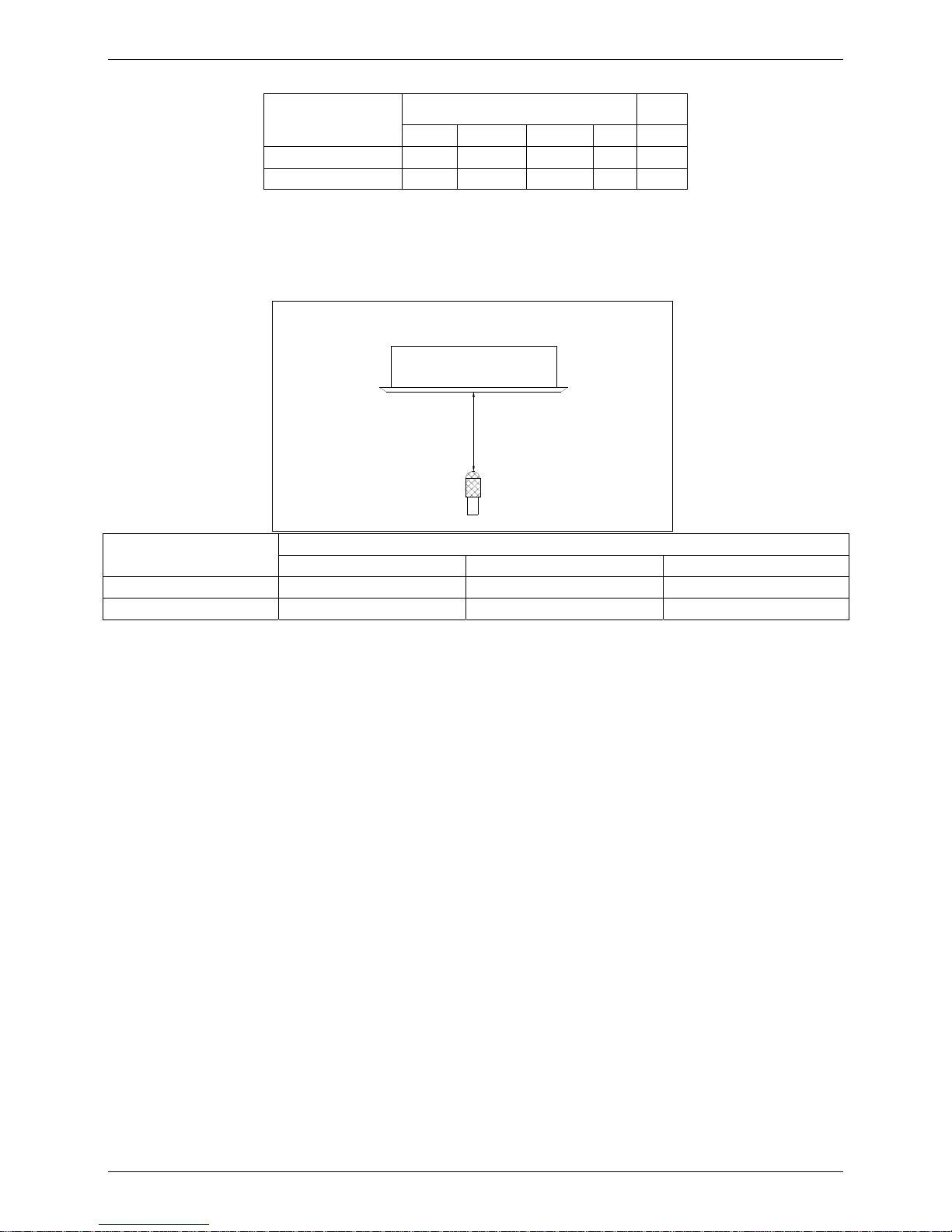
7. Sound Levels
1.4m
Microphone
Model
Noise level dB(A)
H M L
MCA2-12HRDN1-Q 42 41 38
MCA2-18HRDN1-Q 42 41 38
Page 20
Accessories
16
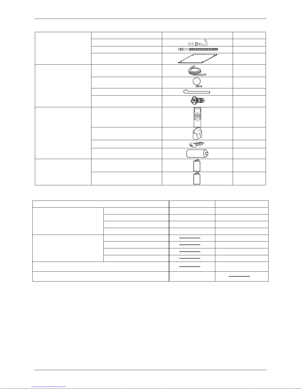
8. Accessories
Installation fittings
Name Shape Quantity
1. Expansible hook
4
2. Installation hook
4
3. Installation paper board
1
Drainpipe Fittings
4. Out-let pipe sheath
1
5. Out-let pipe clasp 1
6. Tightening band
20
7. Drain joint 1
Remote controller & Its
holder
8. Remote controller
1
9. Remote controller holder 1
10. Mounting screw(ST2.9×10-C-H) 2
11. Alkaline dry batteries (AM4)
2
Others
12. Owner's manual
1
13. Installation manual 1
9. The Specification of Power
Model 12000Btu/h 18000 Btu/h
INDOOR UNIT POWER
Phase 1-phase 1-phase
Frequency and Voltage 220-240V, 50Hz 220-240V, 50Hz
POWER WIRING (mm2) 3×2.5 3×1.0
CIRCUIT BREAKER (A) 20 15
OUTDOOR UNIT POWER
Phase
1-phase
Frequency and Voltage 220-240V, 50Hz
POWER WIRING (mm2) 3×2.5
CIRCUIT BREAKER (A) 30
Indoor/Outdoor Connecting Wiring
(Weak Electric Signal) (mm
2
)
3×0.5
Indoor/Outdoor Connecting Wiring
(Strong Electric Signal) (mm
2
)
4×2.5
Page 21
Field Wiring
17
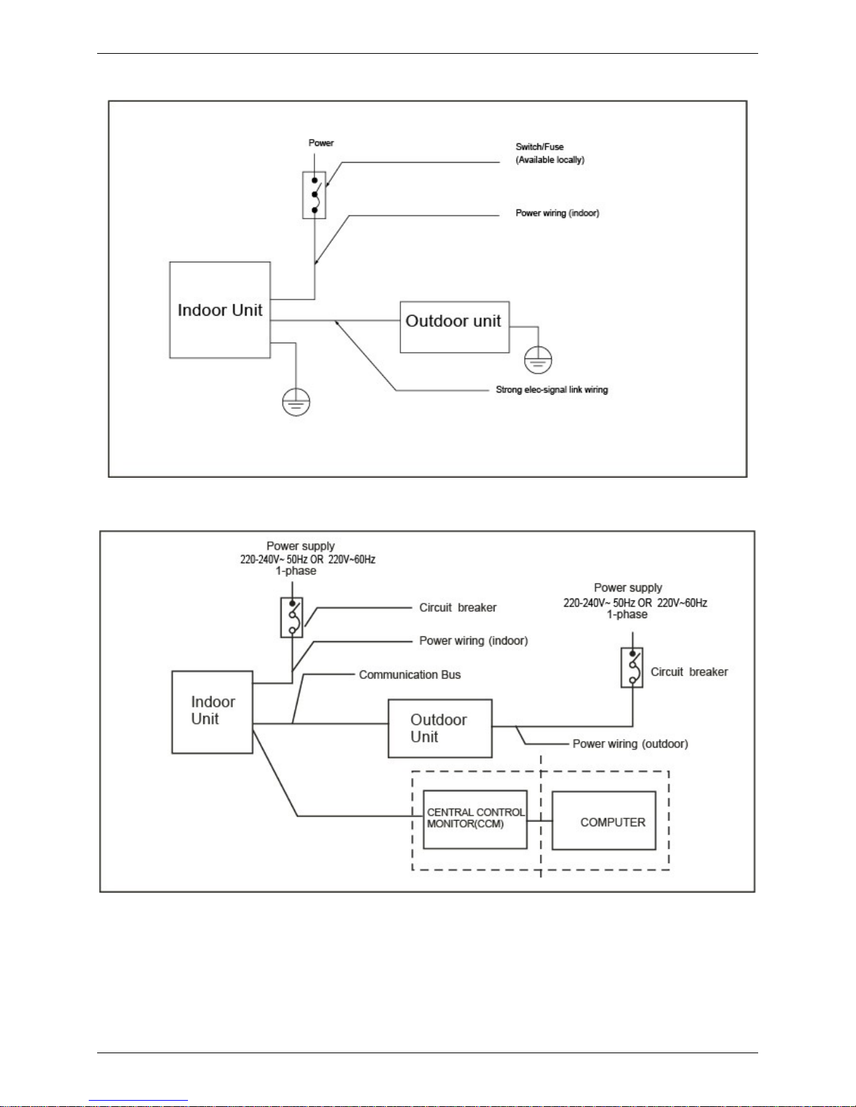
10. Field Wiring
MCA2-12HRDN1-Q
MCA2-18HRDN1-Q
Page 22
Field Wiring
18
MCA2-12HRDN1-Q
MCA2-18HRDN1-Q
Page 23

Four-way Cassette Type
Four-way Cassette Type 19
Four-way Cassette Type
1. Features ................................................................................................. 22
2. Dimensions ........................................................................................... 25
3. Service Space........................................................................................ 26
4. Wiring Diagrams ................................................................................... 27
5. Air Velocity and Temperature Distributions(Reference Data) .......... 22
6. Electric Characteristics ........................................................................ 23
7. Sound Levels ........................................................................................ 23
8. Accessories ........................................................................................... 24
9. The Specification of Power .................................................................. 25
10. Field Wiring ......................................................................................... 26
Page 24
Features
22 Four-way Cassette Type
1. Features
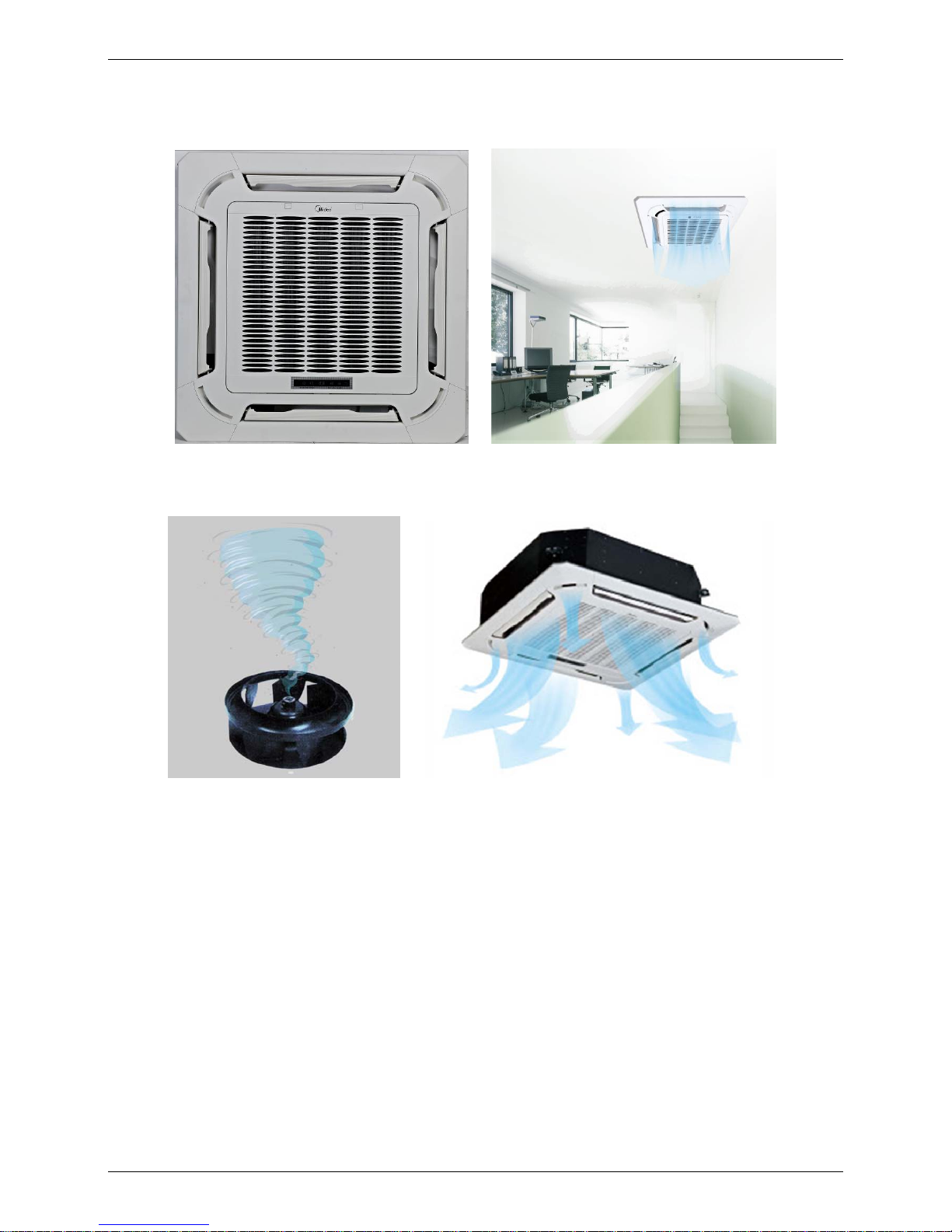
1.1 New panel (60k standard)
New panel with 360° airflow supply
Air intake grille lift function for supper thin cassette, convenient for maintenance.
1.2 3D screw fan technology
3D screw indoor fan technology reduces the air resistance, increases the air volume and improves the
heat exchange efficiency. Operate quietly.
Page 25
Features
Four-way Cassette Type 23
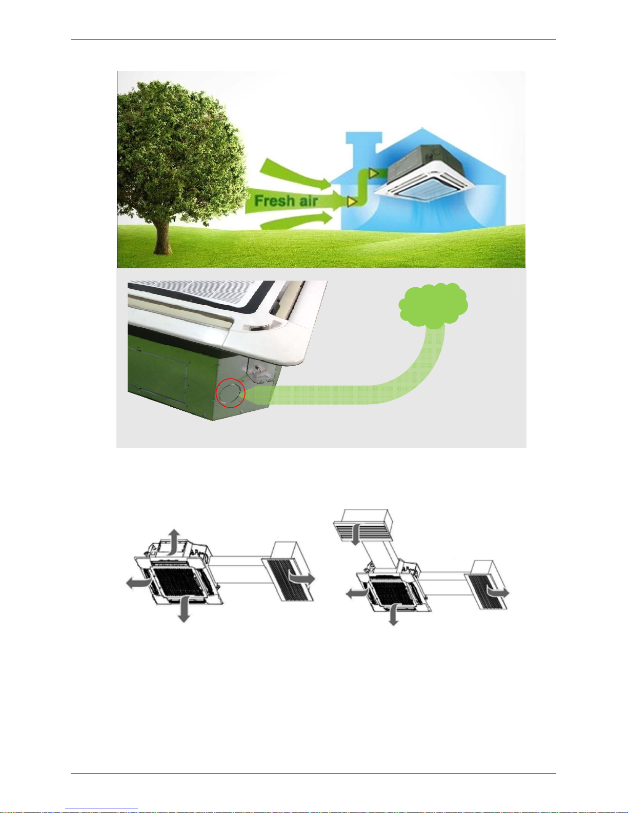
1.3 Fresh air intake function
Fresh air fulfills air quality more healthy and comfortable.
1.4 Air passage function
Reserves the space for air outlet from the side of indoor unit; It’s availed to connect air duct from side to
nearby small rooms.
For duct connecting
Dimension:Φ75mm
Fresh
Air
Page 26
Features
24 Four-way Cassette Type
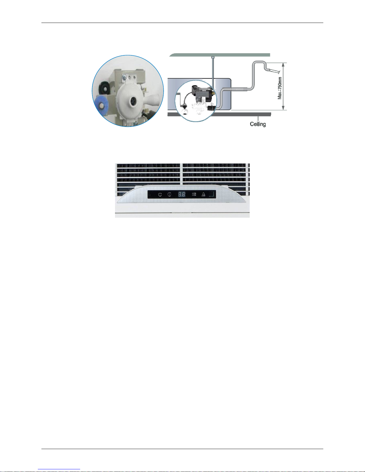
1.5 Drainage pump
Build-in water pump which pumping head is 750mm upmost. It’s convenient to install drainage piping
under most space condition.
1.6 LED display
Digital LED interface, makes the unit more elegant.
Normally display the setting temperature
LED can display the Error Code to make the malfunction checking easier.
Page 27
Dimensions
Four-way Cassette Type 25
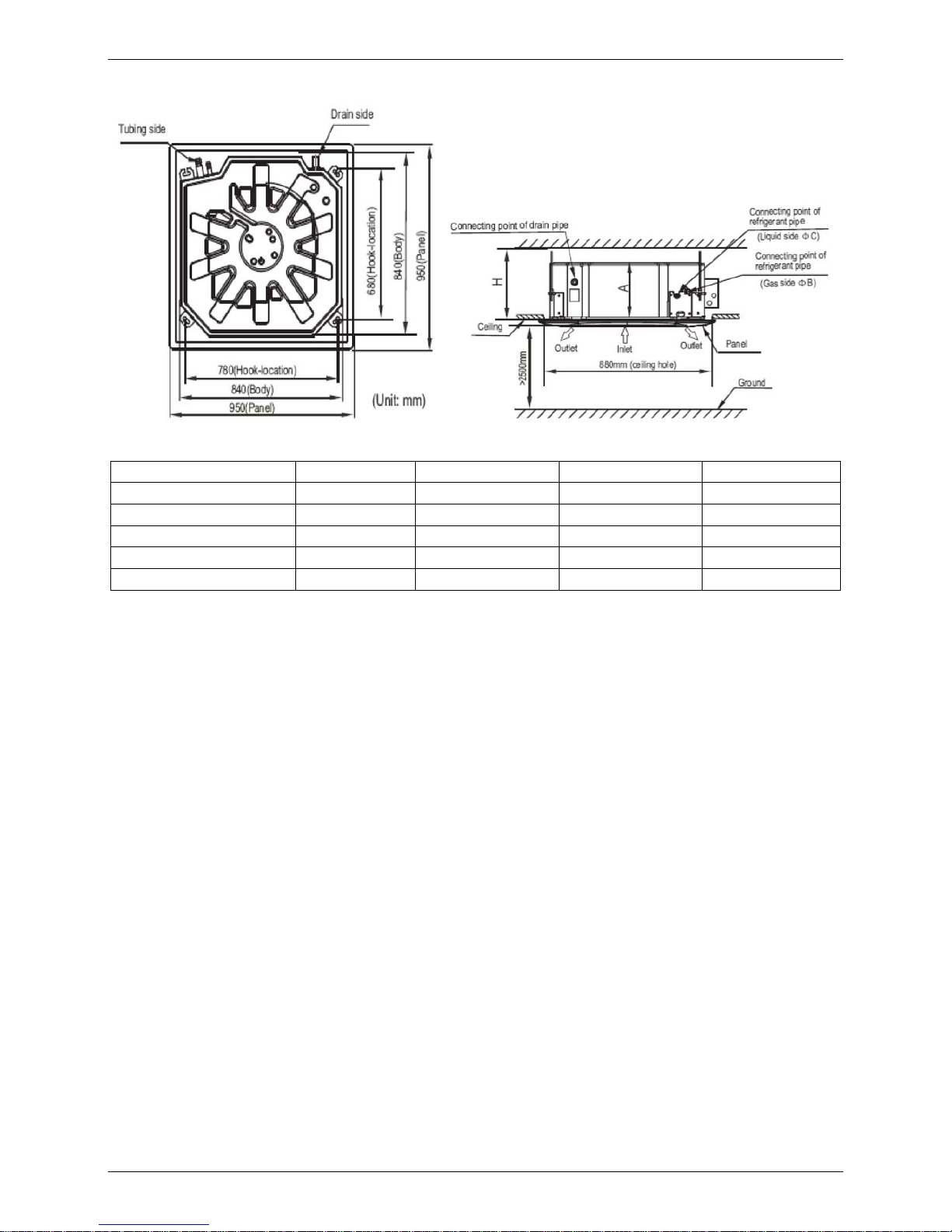
2. Dimensions
Unit: mm
MODEL(Btu/h) A B C H
24000 230 Ф15.9 Ф9.5 >260
30000 300 Ф15.9 Ф9.5 >330
36000 300 Ф15.9 Ф9.5 >330
48000 300 Ф15.9 Ф9.5 >330
60000 300 Ф15.9 Ф9.5 >330
Page 28
Service Space
26 Four-way Cassette Type
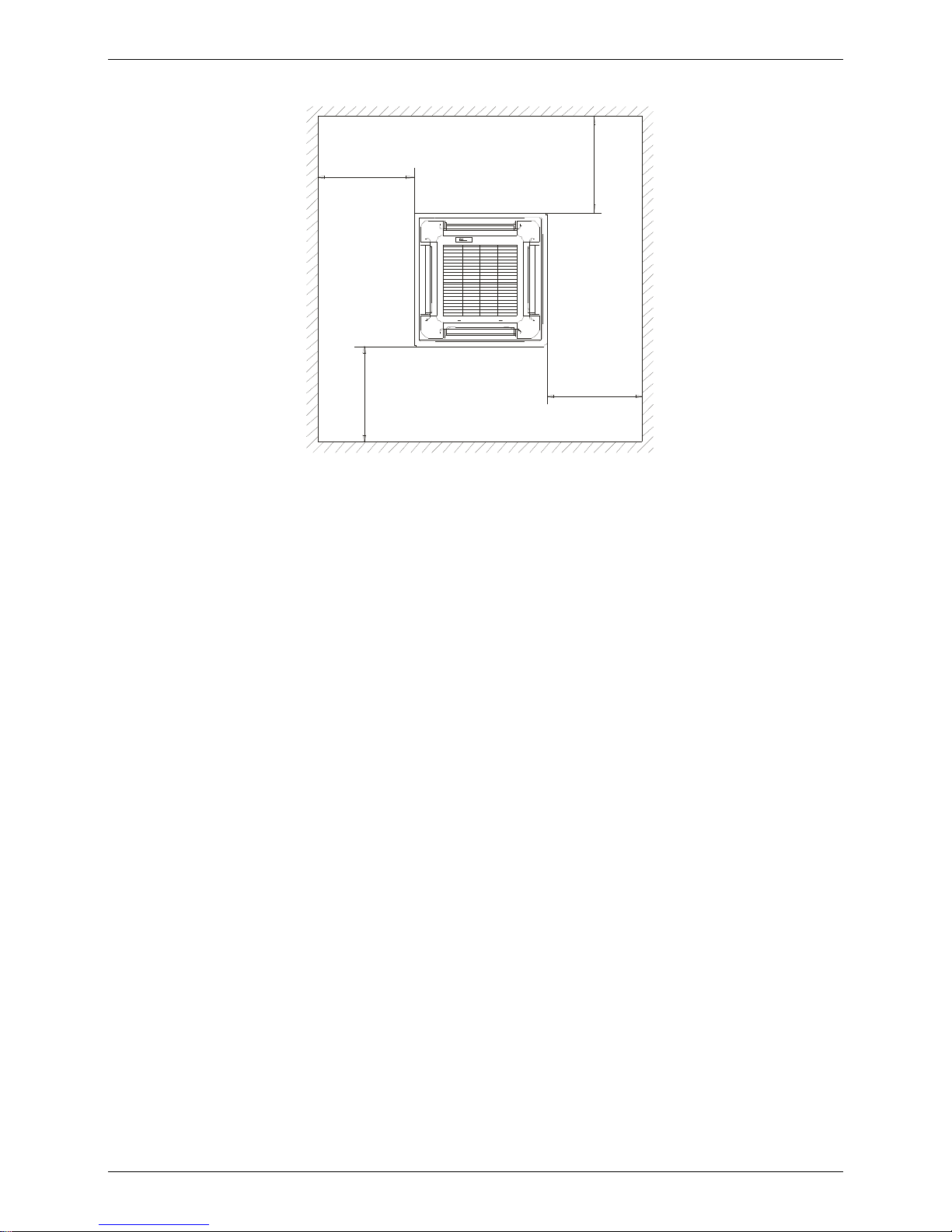
3. Service Space
>1000 mm
>1000mm
>1 000mm
>1000mm
Page 29
Wiring Diagrams
Four-way Cassette Type 27
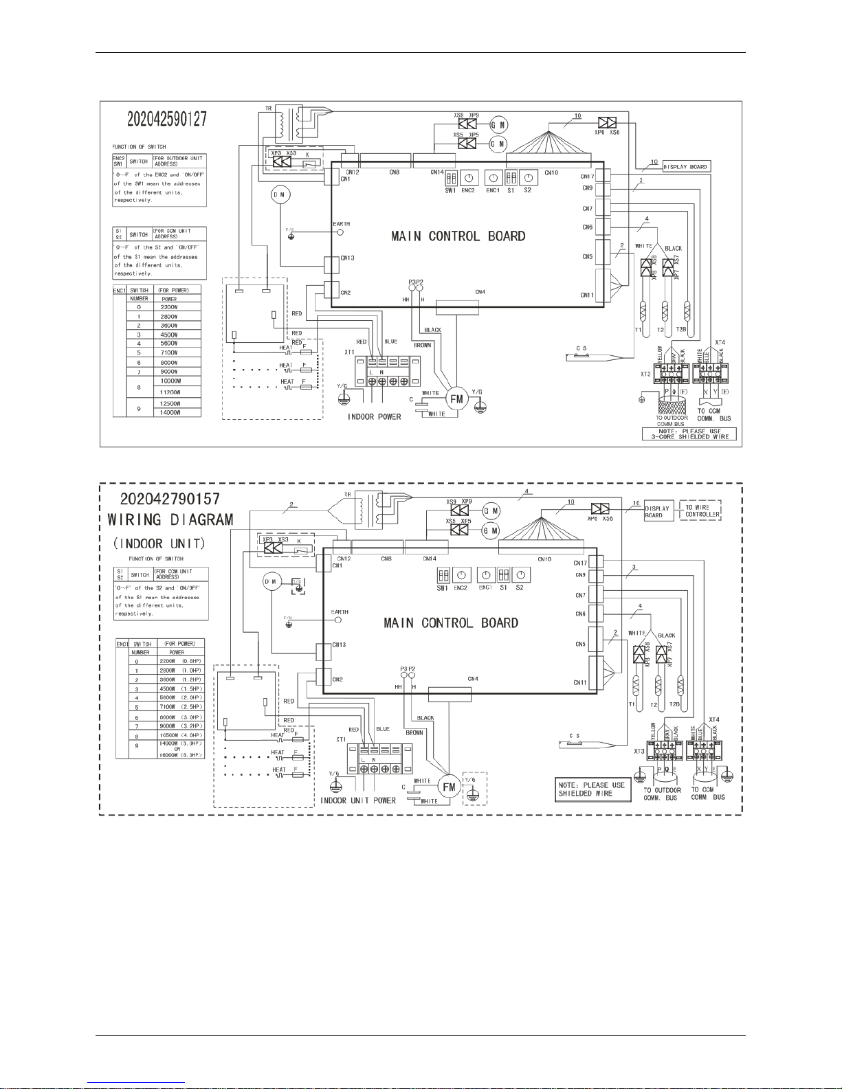
4. Wiring Diagrams
MCC-24HRDN1-Q
MCC-30HRDN1-Q
Page 30

Page 31

Wiring Diagrams
Four-way Cassette Type 21
MCC-36HRDN1-Q MCC-48HRDN1-Q MCC-60HRDN1-R
Page 32

Air Velocity and Temperature Distributions(Reference Data)
22 Four-way Cassette Type
5. Air Velocity and Temperature Distributions(Reference Data)
Airflow velocity
Electronic
expansion valve
Oil s epara tor
Compressor
Low pressure
switch
Oil return
Capillary
High pressure switch
Low pressure l iqui d
accumulator
Evaporator
Capillary
Outdoor unit
Indoor unit
4-way valve
Condenser
T5
Discharge temp. sensor
Filter
Filter
Condenser temp. sensor
T3
T4
Ambient temp. sensor
Filter
Filter
T2
Evaporator temp. sensor
Room temp. sensor
T1
Page 33

Four-way Cassette Type
Four-way Cassette Type 23
6. Electric Characteristics
Model
Indoor Unit
Power
Supply
Hz Voltage Min Max MFA
MCC-24HRDN1-Q 50 220-240 198 254 15
MCC-30HRDN1-Q 50 220-240 198 254 15
MCC-36HRDN1-Q 50 220-240 198 254 15
MCC-48HRDN1-Q 50 220-240 198 254 15
MCC-60HRDN1-R 50 220-240 198 254 15
Notes:
MFA: Max. Fuse Amps. (A)
7. Sound Levels
1.4m
Microphone
Model
Noise level dB(A)
H M L
MCC-24HRDN1-Q
42 41 39
MCC-30HRDN1-Q
44 42 41
MCC-36HRDN1-Q
44 42 41
MCC-48HRDN1-Q
44 42.5 41
MCC-60HRDN1-R
47 44 43
Page 34

Accessories
24 Four-way Cassette Type
8. Accessories
INSTALLATION FITTINGS
Name Shape Quantity
Installation paper board
1
Tubing & Fittings
Soundproof / insulation sheath
2
Connecting pipe group 1
Drainpipe Fittings
Out-let pipe sheath
1
Out-let pipe clasp 1
Drain joint 1
Seal ring 1
Remote controller & Its
Frame
Remote controller & Its Frame
1
Remote controller holder 1
Mounting screw(ST2.9×10-C-H) 2
Alkaline dry batteries (AM4)
2
Others
Owner's manual 1
Installation manual 1
Installation accessory
(The product you have
might not be provided the
following accessories
Expansible hook
4
Installation hook
4
Orifice
1
Page 35

Four-way Cassette Type
Four-way Cassette Type 25
9. The Specification of Power
Model 18000-30000Btu/h 36000-60000 Btu/h 30000-60000 Btu/h
INDOOR UNIT POWER
Phase 1-phase 1-phase 1-phase
Frequency and Voltage 220-240V, 50Hz 220-240V, 50Hz 220-240V, 50Hz
POWER WIRING (mm2) 3×1.0 3×1.0 3×1.0
CIRCUIT BREAKER (A) 15 15 15
OUTDOOR UNIT POWER
Phase 1-phase 1-phase 3-phase
Frequency and Voltage 220-240V, 50Hz 220-240V, 50Hz 380-420V, 50Hz
POWER WIRING (mm2) 3×2.5 3×4.0 5×2.5
CIRCUIT BREAKER (A) 30 40 30
Indoor/Outdoor Connecting Wiring
(Weak Electric Signal) (mm
2
)
3×0.5 3×0.5 3×0.5
Indoor/Outdoor Connecting Wiring
(Strong Electric Signal) (mm
2
)
Page 36

Field Wiring
26 Four-way Cassette Type
10. Field Wiring
Wiring chart
Page 37

Super Slim Cassette Type
Super Slim Cassette Type 27
Super Slim Cassette Type
1. Features ................................................................................................ 28
2. Dimensions .......................................................................................... 32
3. Service Space ...................................................................................... 33
4. Wiring Diagrams .................................................................................. 34
5. Air Velocity and Temperature Distributions(Reference Data) ......... 35
6. Electric Characteristics....................................................................... 36
7. Sound Levels ....................................................................................... 37
8. Accessories ......................................................................................... 38
9. The Specification of Power ................................................................. 39
10.Field Wiring .......................................................................................... 40
Page 38

Features
28 Super Slim Cassette Type
1. Features
1.1 Overview
Compact design, super slim body size, less space requiring in installation
Each louver can be separately controlled, more comfort air blowing is possible.
Auto-lifting panel design, more convenient to clean and maintain the filter. (optional)
Old Cassette New slim cassette Volume change
Dimension
18K-24K: 840*230*840 18K-24K: 840*205*840
11%↓
30K: 840*300*840 30K: 840*205*840
32%↓
36K-48K: 840*300*840 36K-48K: 840*245*840
18%↓
1.2
Fresh air intake function
Fresh air fulfills air quality more healthy and comfortable.
Ventilation motor is optional to increase the effect of fresh air.
Page 39

Features
Super Slim Cassette Type 29
1.3 Optional ionizer generator
Ionizer generator is optional to get refreshing air to your room.
Ionizer can be switched on or off by remote controller.
When pressing the Clean Air button on the remote controller, Ionizer will work and the indicator light on
display board will shine.
New air-intake
IIoonniizzeerr ggeenneerraattoorr
ccoonnnneeccttoorr
VVeennttiillaattiioonn mmoottoorr
ccoonnnneeccttoorr
Page 40

Features
30 Super Slim Cassette Type
1.4 External air duct design
Reserve external air duct, more flexible for the air supply.
1.5
Built-in draining pump
Due to the improvement of structure, more convenient to repair or replace the draining pump.
Built-in draining pump to make sure condensed water drain out reliably.
Draining Pump
Page 41

Features
Super Slim Cassette Type 31
1.6 Terminals for alarm lamp and long-distance on-off controller connection are
standard
Reserve terminals for the connection of alarm lamp and long-distance on-off controller, more human
control.
1.7 Optional touch screen wired controller
Touch screen wired controller is optional, with error code indication function. Better
man-machine conversation interface.
Undated structure design, 4-way wire layout design, no raised part at backside, more convenient to
place the wires and install the device.
1.8 Twins Combination(18k-30k)
The units can be installed as Twin systems: one outdoor unit can connect with two indoor units. The
indoor units can be combined in any of the different available ratings.
Alarm lamp
Long-distance on-off controller
Page 42

Dimensions
32 Super Slim Cassette Type
2. Dimensions
Model A H
18-30 205 >235
36-48 245 >275
60 287 >312
Page 43

Service Space
Super Slim Cassette Type 33
3. Service Space
>1000 mm
>1000mm
>1000mm
>1000mm
Page 44

Wiring Diagrams
34 Super Slim Cassette Type
4. Wiring Diagrams
MCD-18HRDN1-Q MCD-24HRDN1-Q MCD-30HRDN1-Q MCD-36HRDN1-Q MCD-48HRDN1-Q
MCD-60HRDN1-Q
Page 45

Air Velocity and Temperature Distributions(Reference Data)
Super Slim Cassette Type 35
5. Air Velocity and Temperature Distributions(Reference Data)
Airflow velocity
Electronic
expansion valve
Oil s epara tor
Compressor
Low pressure
switch
Oil return
Capillary
High pressure switch
Low pressure l iqui d
accumulator
Evaporator
Capillary
Outdoor unit
Indoor unit
4-way valve
Condenser
T5
Discharge temp. sensor
Filter
Filter
Condenser temp. sensor
T3
T4
Ambient temp. sensor
Filter
Filter
T2
Evaporator temp. se nsor
Room temp. sensor
T1
Page 46

Electric Characteristics
36 Super Slim Cassette Type
6. Electric Characteristics
Model
Indoor Unit
Power
Supply
Hz Voltage Min Max MFA
MCD-18HRDN1-Q
50 220-240 198 254 15
MCD-24HRDN1-Q
50 220-240 198 254 15
MCD-30HRDN1-Q
50 220-240 198 254 15
MCD-36HRDN1-Q
50 220-240 198 254 15
MCD-48HRDN1-Q
50 220-240 198 254 15
MCD-60HRDN1-Q
50 220-240 198 254 15
Notes:
MFA: Max. Fuse Amps. (A)
Page 47

Sound Levels
Super Slim Cassette Type 37
7. Sound Levels
1.4m
Microphone
Model
Noise level dB(A)
H M L
MCD-18HRDN1-Q
37 34 32
MCD-24HRDN1-Q
43 41 38
MCD-30HRDN1-Q
46 45 43
MCD-36HRDN1-Q
48 46 45
MCD-48HRDN1-Q
48 46 45
MCD-60HRDN1-Q
55 51 48
Page 48

Accessories
38 Super Slim Cassette Type
8. Accessories
INSTALLATION FITTINGS
Name Shape Quantity
Installation paper board
1
Bolt M5 4
Tubing & Fittings Soundproof / insulation sheath
2
Drainpipe Fittings
Out-let pipe
1
Out-let pipe sheath
1
Out-let pipe clasp 1
Remote controller & Its
Frame
Remote controller & Its Frame
1
Remote controller holder 1
Mounting screw(ST2.9×10-C-H) 2
Remote controller manual 1
Alkaline dry batteries (AM4)
2
Others
Owner's manual
1
Installation manual 1
Network wires
1
Installation accessory
(The product you have
might not be provided the
following accessories
Expansible hook
4
Installation hook
4
Orifice
1
Page 49

The Specification of Power
Super Slim Cassette Type 39
9. The Specification of Power
Model 18000-24000Btu/h 30000-60000 Btu/h
INDOOR UNIT POWER
Phase 1-phase 1-phase
Frequency and Voltage 220-240V, 50Hz 220-240V, 50Hz
POWER WIRING (mm2) 3×1.0 3×1.0
CIRCUIT BREAKER (A) 15 15
OUTDOOR UNIT POWER
Phase 1-phase 1-phase
Frequency and Voltage 220-240V, 50H 220-240V, 50H
POWER WIRING (mm2) 3×2.5 3×4.0
CIRCUIT BREAKER (A) 30 40
Indoor/Outdoor Connecting Wiring
(Weak Electric Signal) (mm
2
)
3×0.5 3×0.5
Indoor/Outdoor Connecting Wiring
(Strong Electric Signal) (mm
2
)
Page 50

Field Wiring
40 Super Slim Cassette Type
10. Field Wiring
MCD-18HRDN1-Q MCD-24HRDN1-Q MCD-30HRDN1-Q MCD-36HRDN1-Q MCD-48HRDN1-Q
MCD-60HRDN1-Q
Page 51

Duct Type
Duct Type 41
Duct Type
1. Features ........................................................................................................ 42
2. Dimensions ................................................................................................... 45
3. Service Space ............................................................................................... 46
4. Wiring Diagrams ........................................................................................... 47
5. Static Pressure ............................................................................................. 49
6. Electric Characteristics ............................................................................... 51
7. Sound Levels ................................................................................................ 52
8. Accessories .................................................................................................. 53
9. The Specification of Power ......................................................................... 54
10. Field Wiring ................................................................................................. 55
Page 52

Features
42 Duct Type
1. Features
1.1 Installation accessories: (Optional)
Front Board, Canvas Air Passage, Filter, Panel, for easy installation
1.2 Easy Installation: Two air inlet styles (Bottom side or Rear side)
Air inlet from rear is standard for all capacity; air inlet from bottom is optional.
The size of air inlet frame from rear and bottom is same, it’s very easy to move the cover from bottom to
rear side, or from rear to the bottom, in order to matching the installation condition.
1.3 Fresh air intake function(Optional for 18~60k)
Install one duct from the reserved fresh-air intake to outdoor.
Continually inhale the fresh air to improve the quality of the indoor air, fulfills air quality more healthy and
comfortable.
1.4 Easy maintenance
Clean the filter (Optional, standard product without filter)
It is easy to draw out the filter from the indoor unit for cleaning, even the filter is installed in rear side or
bottom side.
Front Board
Canvas Air Passage Filter Panel
Air intake from rear (Standard)
Air intake from bottom (Optional)
Page 53

Features
Duct Type 43
Replace the motor or centrifugal fan
Remove the ventilated panel firstly. Remove a half of blower housing and take out the motor with
centrifugal fan. Directly remove two bolts, and then replace the motor or centrifugal fan easily.
1.5 Reserved remote on-off and central control ports
Reserved remote on-off ports and central control ports, can connect the cable of an on-off controller or a
central controller to realize remote on-off control function or group control function.
1.6 Built-in drain pump (Optional):
Built-in drain pump can lift the water to 750mm upmost. It’s convenient to install drainage piping under
most space condition.
Motor
Blower Housing
Ventilated Panel
Remote on-off ports
Central control ports
Page 54

Features
44 Duct Type
1.7 Built-in display board
The standard indoor unit can be controlled by wired controller.
There is a display board with a receiver in the E-box. Move out the display, and fix it in other place, even
in the distance of 10m. The unit will realized remoter control.
The wired controller and the display board can display the error code or production code when the chips
detect some failure.
1.8 Twins Combination(18k-30k)
The units can be installed as Twin systems: one outdoor unit can connect with two indoor units. The
indoor units can be combined in any of the different available ratings.
Display
750mm upmost
Wired Controller (Standard)
Remote Controller (Optional)
Page 55

Dimensions
Duct Type 45
2. Dimensions
H
G
E
F
A
B
D
C
L
M
Capacity
(KBtu)
Outline dimension(mm) Air outlet opening size Air return opening size
Size of outline
dimension mounted
plug
A B C D E F G H I J K L M
12 700 210 635 570 65 493 35 119 595 200 80 740 350
18 920 210 635 570 65 713 35 119 815 200 80 960 350
24 920 270 635 570 65 713 35 179 815 260 20 960 350
30/36 1140 270 775 710 65 933 35 179 1035 260 20 1180 490
48/60 1200 300 865 800 80 968 40 204 1094 288 45 1240 500
Page 56

Service Space
46 Duct Type
3. Service Space
Ensure enough space required for installation and maintenance.
All the indoor units reserve the hole to joint the fresh air pipe. The hole size as following:
Page 57

Wiring Diagrams
Duct Type 47
4. Wiring Diagrams
MTB1-12HWDN1-Q
MTB-18HWDN1-Q 、MTB-24HWDN1-Q、MTB-30HWDN1-Q
Page 58

Wiring Diagrams
48 Duct Type
MTB-36HWDN1-Q MTB-48HWDN1-Q MTB-60HWDN1-R
Page 59

Static Pressure
Duct Type 49
5. Static Pressure
12,000Btu/h 18,000Btu/h
Super high speed
0
900
600
500
Mid speed
High speed
External static pressure (Pa)
3
Air volume(m /h)
Pa
90
80
70
60
50
40
30
20
10
Low speed
300 400
700
800
Super high speed
500
400300
200
Low speed
10
20
30
40
50
60
70
80
90
Pa
600 700 800 900 1000 1100
Air volume(m
/h)
3
External static pressure (Pa)
High speed
Mid speed
1200
24,000Btu/h 36,000Btu/h
Super high speed
14001300
Low speed
10
20
30
40
50
60
70
80
90
Pa
800 900 1000 1100
Air volume(m
/h)
3
External static pressure (Pa)
High speed
Mid speed
1200
1500
700
2400
2200
16001400
Low speed
10
20
30
40
50
60
70
80
90
1100
Air volume(m
/h)
3
External static pressure (Pa)
High speed
Mid speed
1200
1800
2000
Super high speed
Pa
Page 60

Static Pressure
50 Duct Type
48,000Btu/h 60,000Btu/h
120
110
Super high speed
100
Pa
2500
2200
1300
Mid speed
High speed
E
x
t
erna
l
s
t
a
ti
c pressure
(P
a
)
3
Air volume(m /h)
1000
90
80
70
60
50
40
30
20
10
Low speed
1600 1900
2800
3100
120
110
Super high speed
3400
100
3100
2800
19001600
Low speed
10
20
30
40
50
60
70
80
90
Pa
1000
Air volume(m
/h)
3
External static pressure (Pa)
High speed
Mid speed
1300
2200
2500
Page 61

Electric Characteristics
Duct Type 51
6. Electric Characteristics
Model
Indoor Unit Power Supply
Hz Voltage Min. Max. MFA
MTB1-12HWDN1-Q 50 220-240 198 254 15
MTB-18HWDN1-Q 50 220-240 198 254 15
MTB-24HWDN1-Q 50 220-240 198 254 15
MTB-30HWDN1-Q 50 220-240 198 254 15
MTB-36HWDN1-Q 50 220-240 198 254 15
MTB-48HWDN1-Q 50 220-240 198 254 15
MTB-60HWDN1-R 50 220-240 198 254 15
Notes:
MFA: Max. Fuse Amps. (A)
Page 62

Sound Levels
52 Duct Type
7. Sound Levels
Suction
Discharge
Microphone
1.4m
Concealed Duct Type
DuctDuct
Model
Noise level dB(A)
H M L
MTB1-12HWDN1-Q 37 30 26
MTB-18HWDN1-Q 44 36 33
MTB-24HWDN1-Q 45 43 41
MTB-30HWDN1-Q 46 44 42
MTB-36HWDN1-Q 46 44 42
MTB-48HWDN1-Q 47 41 37
MTB-60HWDN1-R 47 45 43
Page 63

Accessories
Duct Type 53
8. Accessories
Tubing & Fittings
Name Shape Quantity
Soundproof / insulation sheath
2
Binding tape
1
Seal sponge
1
Drainpipe Fittings
(for cooling & heating)
Drain joint
1
Seal ring
1
Wired controller & Its Frame
Wired controller
1
Others
Owner
,
s manual
1
Installation manual
1
EMS & It’s fitting
Magnetic ring (twist the electric wires L
and N around it to five circles)
1
Page 64

The Specification of Power
54 Duct Type
9. The Specification of Power
Model 12000Btu/h 18000-30000Btu/h
36000-60000
Btu/h
30000-60000
Btu/h
INDOOR UNIT
POWER
Phase 1-phase 1-phase 1-phase 1-phase
Frequency and
Voltage
220-240V, 50Hz 220-240V, 50Hz 220-240V, 50Hz 220-240V, 50Hz
POWER WIRING
(mm
2
)
3×1.5 3×1.0 3×1.0 3×1.0
CIRCUIT BREAKER
(A)
15 15 15 15
OUTDOOR UNIT
POWER
Phase 1-phase 1-phase 3-phase
Frequency and
Voltage
220-240V, 50Hz 220-240V, 50Hz 380-420V, 50Hz
POWER WIRING
(mm
2
)
3×2.5 3×4.0 5×2.5
CIRCUIT BREAKER
(A)
30 40 40
Indoor/Outdoor Connecting Wiring
(Weak Electric Signal) (mm
2
)
4×1.5 3×0.5 3×0.5 3×0.5
Indoor/Outdoor Connecting Wiring
(Strong Electric Signal) (mm
2
)
Page 65

Field Wiring
Duct Type 55
10. Field Wiring
Page 66

Field Wiring
56 Duct Type
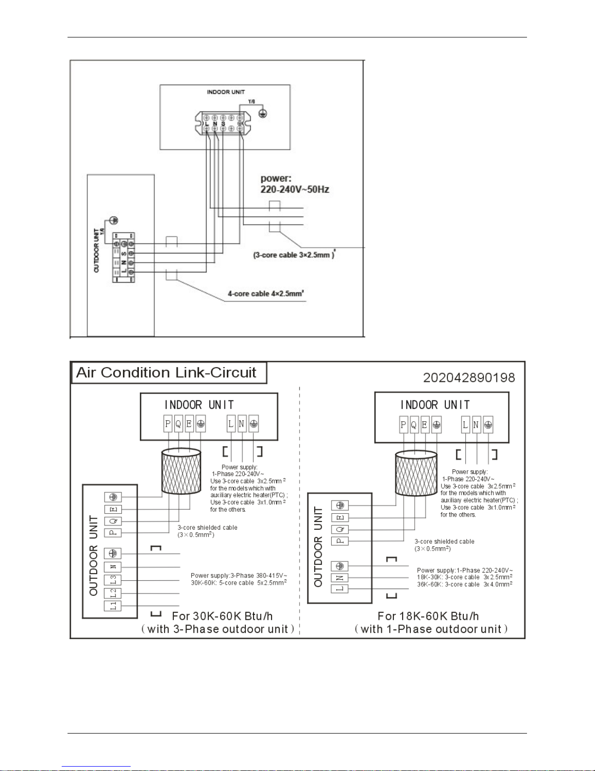
Air-conditioner link-circuit.
For model 12
For model 18-60
Page 67

Ceiling & Floor Type
Ceiling & Floor Type 57
Ceiling & Floor Type
1. Features ................................................................................................. 58
2. Dimensions ........................................................................................... 60
3. Service Space........................................................................................ 61
4. Wiring Diagrams ................................................................................... 61
5. Air Velocity and Temperature Distributions(Reference Data) .......... 64
6. Electric Characteristics ........................................................................ 66
7. Sound Levels ........................................................................................ 66
8. Accessories ........................................................................................... 67
9. The Specification of Power .................................................................. 68
10. Field Wiring ......................................................................................... 69
Page 68

Features
58 Ceiling & Floor Type
1. Features
1.1 Two-way installation
The rounded design of the ceiling and floor type air conditioner allows either ceiling or floor-level
installation. Ceiling installation saves room space, while floor installation helps prevent the loss of warm
air.
1.2 Brief design
Brief design that is suitable for any interior will not only give you cooling and heating performance but
also upgrade your lifestyle.
1.3 3D airflow
Vertical air flow and horizontal airflow can be adjusted by remote controller, the cooperation of the two
airflow ways help to spread air comfortably throughout even a large room. With these functions, the
whole room can be evenly air-conditioned for both floor-level and ceiling installation.
Page 69

Features
Ceiling & Floor Type 59
1.4 Optional drainage pipe connection
Both right side and left side drainage holes are available to avoid the space limitation for drainage pipe
installation. Make you more convenient during installation.
1.5 Five panels for optional
Standard Panel A Panel B Panel (LED display)
C Panel (LED display) D Panel
1.6 Convenience operating and easy maintenance
Remote controller as standard, wired controller for optional.
The filter without screw fixed, can be took out easily.
1.7 Easy installation, save working time
The pipes can be connected from bottom, back and right side, makes the installation more easily.
The wiring works can be finished before installation.
1.8 Outside water pump for optional when ceiling installation.
Page 70

Dimensions
60 Ceiling & Floor Type
2. Dimensions
a. Wall mounting installation
B
A
C
D
E
b. Ceiling installation
F
>20mm
G
Capacity (Btu/h) A B C D E F G
12000-24000 990 660 203 505 506 907 200
36000 1280 660 203 795 506 1195 200
48000-60000 1670 680 240 1070 450 1542 200
Notes:
The dimension of 12000Btu/h and 24000Btu/h are the same
The dimension of 48000Btu/h and 60000Btu/h are the same
Page 71

Service Space
Ceiling & Floor Type 61
3. Service Space
C
≥35mm
≥35mm
≥35mm
≥1000mm
4. Wiring Diagrams
MUB-12HRDN1-Q
Page 72

Wiring Diagrams
62 Ceiling & Floor Type
MUB-18HRDN1-Q、MUB-24HRDN1-Q
MUB-30HRDN1-Q
Page 73

Wiring Diagrams
Ceiling & Floor Type 63
MUB-36HRDN1-Q MUB-48HRDN1-Q MUB-60HRDN1-R
Remark:
SW1:Temperature selection of anti-cold-air function
SW2: Floor or Ceiling installation selection
SW3: Temperature compensation selection. The default temperature compensation value is 1℃ for floor
installation and 6℃ for ceiling installation, and can not be changed by the user. If the other temperature
required, modification should be done in factory.
SW4: Auto restart function selection
Page 74

Air Velocity and Temperature Distributions(Reference Data)
64 Ceiling & Floor Type
5. Air Velocity and Temperature Distributions(Reference Data)
Discharge angle 60° (CEILING)
Airflow velocity
Electronic
expansion valve
Oil separator
Compressor
Low pressure
switch
Oil return
Capillary
High pressure switch
Low pressure liquid
accumulator
Evaporator
Capillary
Outdoor unit
Indoor unit
4-way valve
Condenser
T5
Discharge temp. sensor
Filter
Filter
Condenser temp. sensor
T3
T4
Ambient temp. sensor
Filter
Filter
T2
Evaporator temp. sensor
Room temp. sensor
T1
Page 75

Air Velocity and Temperature Distributions(Reference Data)
Ceiling & Floor Type 65
Discharge angle 60°(FLOOR)
Airflow velocity
Temperature
Page 76

Electric Characteristics
66 Ceiling & Floor Type
6. Electric Characteristics
Model
Indoor Unit Power Supply
Hz
V
oltage Min Max MFA
MUB-12HRDN1-Q 50 220~240 198 254 20
MUB-18HRDN1-Q 50 220~240 198 254 15
MUB-24HRDN1-Q 50 220~240 198 254 15
MUB-30HRDN1-Q 50 220~240 198 254 15
MUB-36HRDN1-Q 50 220~240 198 254 15
MUB-48HRDN1-Q 50 220~240 198 254 15
MUB-60HRDN1-R 50 220~240 198 254 15
Notes:
MFA: Max. Fuse Amps. (A)
7. Sound Levels
Microphone
1m
1m
Air outlet side
1.5m
1m
Microphone
Ceiling Floor
Model
Noise level dB(A)
H M L
MUB-12HRDN1-Q 40 37 33
MUB-18HRDN1-Q 43 41 38
MUB-24HRDN1-Q 45 43 40
MUB-30HRDN1-Q 45 43 40
MUB-36HRDN1-Q 45 43 40
MUB-48HRDN1-Q 49 47 46
MUB-60HRDN1-R 47 46 44
Page 77

Accessories
Ceiling & Floor Type 67
8. Accessories
Installation fittings
Name Shape Quantity
1.Hook 2
2.Hanging arm
2
Remote controller & Its
holder
3. Remote controller
1
4. Remote controller holder 1
5. Mounting screw (ST2.9×10-C-H) 2
6. Alkaline dry batteries (AM4) 2
Others
7. Owner's manual
1
8. Installation manual
1
9. Remote controller manual
1
Page 78

The Specification of Power
68 Ceiling & Floor Type
9. The Specification of Power
Model 12000Btu/h 18000-30000Btu/h
36000-60000
Btu/h
30000-60000
Btu/h
INDOOR UNIT
POWER
Phase 1-phase 1-phase 1-phase 1-phase
Frequency and
Voltage
220-240V, 50Hz 220-240V, 50Hz 220-240V, 50Hz 220-240V, 50Hz
POWER WIRING
(mm
2
)
3×1.5 3×1.0 3×1.0 3×1.0
CIRCUIT BREAKER
(A)
20 15 15 15
OUTDOOR UNIT
POWER
Phase 1-phase 1-phase 3-phase
Frequency and
Voltage
220-240V, 50Hz 220-240V, 50Hz 380-420V, 50Hz
POWER WIRING
(mm
2
)
3×2.5 3×4.0 5×2.5
CIRCUIT BREAKER
(A)
30 40 40
Indoor/Outdoor Connecting Wiring
(Weak Electric Signal) (mm
2
)
4×1.5 3×0.5 3×0.5 3×0.5
Indoor/Outdoor Connecting Wiring
(Strong Electric Signal) (mm
2
)
Page 79

Field Wiring
Ceiling & Floor Type 69
10. Field Wiring
Page 80

Field Wiring
70 Ceiling & Floor Type
For model 12
For model 18~60
Page 81

Console Type
Console Type 71
Console Type
1. Features ................................................................................................. 73
2. Dimensions ........................................................................................... 76
3. Service Space........................................................................................ 77
4. Wiring Diagrams ................................................................................... 78
5. Air Velocity and Temperature Distributions(Reference Data) .......... 79
6. Electric Characteristics ........................................................................ 80
7. Sound Levels ........................................................................................ 81
8. Accessories ........................................................................................... 82
9. The Specification of Power .................................................................. 82
10. Field Wiring ......................................................................................... 83
Page 82

Page 83

Features
Console Type 73
1. Features
1.1. Modern and elegant appearance
The simple and stylish designs can nicely harmonies with your living space.
1.2. Four panels optional
1.3. Two air-outlet ways
Cooling mode
Quick Cooling To maintain room temp
Air outlet from top and bottom to make quick cooling ------When the A/C is just switched on, or room
temp. is still high, cold air will be blown out from top and bottom air outlet to cool down the room quickly
Air outlet from top to maintain room temp. ----When the room has been cooled down, or the A/C has
been opened over 1 hour, cold air only from the top outlet to keep constant room temp
Heating mode
Anti-cold air ------When the AC is just turn on, temperature of evaporator is very low, in this case, in
order to prevent cold air direct blowing, only the upper louver is opened in a high position, the lower
louver closed.
Page 84

Features
74 Console Type
1.4. Four air inlets
1.5. Low noise
DC indoor fan motor, which has five speeds.
Low noise and energy saving.
Advanced centrifugal fan technology makes a fast airflow and reduces the indoor noise lower to 28dB.
1.6. Golden fin is optional.
1.7. Active carbon filter is standard
1.8. Product with quick connector
Optional quick connector of refrigerant pipe is very easy to install.
Page 85

Features
Console Type 75
Page 86

Dimensions
76 Console Type
2. Dimensions
MFA-12HRDN1-Q/ MFA-18HRDN1-Q
Page 87

Service Space
Console Type 77
3. Service Space
Page 88

Wiring Diagrams
78 Console Type
4. Wiring Diagrams
MFA-12HRDN1-Q
MFA-18HRDN1-Q
Page 89

Air Velocity and Temperature Distributions(Reference Data)
Console Type 79
5. Air Velocity and Temperature Distributions(Reference Data)
Discharge angle 60
Airflow velocity
Temperature
Page 90

Electric Characteristics
80 Console Type
6. Electric Characteristics
Model
Indoor Unit Power Supply
Hz
V
oltage Min Max MF
A
MFA-12HRDN1-Q
50 220~240V 198V 254V 16
MFA-18HRDN1-Q
50 220~240V 198V 254V 16
Notes:
MFA: Max. Fuse Amps. (A)
Page 91

Sound Levels
Console Type 81
7. Sound Levels
1.5m
1m
Microphone
Model
Noise level dB(A)
Highest Higher H M
L
MFA-12HRDN1-Q 38 35
33 31
28
MFA-18HRDN1-Q 44 41
39 37
34
Page 92

Accessories
82 Console Type
8. Accessories
Name Shape Quantity
Installation fittings Hook
2
Remote controller & Its Frame
Remote controller
1
Frame
1
Mounting screw(ST2.9×10-C-H)
2
Alkaline dry batteries (AM4)
2
Others
Installation manual / 1
Owner's manual / 1
9. The Specification of Power
Model 12000Btu/h 18000
Power
Phase 1-phase 1-phase
Frequency and
Voltage
220-240V, 50Hz 220-240V, 50Hz
Circuit breaker (A) 20/16 20/16
Indoor power wiring (mm2) 3×1.5
Indoor/Outdoor
connecting wiring
(mm2)
Ground wiring 1.5 2.5
Outdoor power wiring(mm2) 3×2.5
Strong electric signal (mm2) 4×1.5 3×1.5
Weak electric signal(mm2) 3×0.5
Page 93

Field Wiring
Console Type 83
10. Field Wiring
Page 94

Field Wiring
84 Console Type
Page 95

High Static Pressure Duct
High Static Pressure Duct 85
High Static Pressure Duct
1. Features ........................................................................................................ 86
2. Dimensions ................................................................................................... 87
3. Service Space ............................................................................................... 88
4. Wiring Diagrams ........................................................................................... 89
5. Fan Performances ........................................................................................ 90
6. Electric Characteristics ............................................................................... 91
7. Sound Levels ................................................................................................ 91
8. Accessories .................................................................................................. 92
9. The Specification of Power ......................................................................... 93
10. Field Wiring ................................................................................................. 94
Page 96

Features
86 High Static Pressure Duct
1. Features
1.1 High static pressure design
Max static pressure of indoor unit is 160Pa.
The longest distance of air supply is 14m, the max height of air supply is 6.5m.
Specially recommended for spacious and large rooms like large stores and factories.
1.2 Easy maintenance
Reduce time and cost, easily removable fan motor design.
1. Control box
2. Fan casing
3. Motor assembly
4. Bottom panel
1.3 Flexible Installation
Different solutions for any shape room by using kinds of air distribution ducts.
L-sha
p
ed
Areas far
Y-sh a
p
ed
High static pressure design enables long duct.
Outle
t
The height of air
su
pply
is 6.5m
Max. 14m long distance
Indoor Unit
Fresh
Air Intake
Intak
e
Page 97

Dimensions
High Static Pressure Duct 87
2. Dimensions
MHD-36HRDN1-Q MHD-48HRDN1-Q MHD-60HRDN1-R
Page 98

Service Space
88 High Static Pressure Duct
3. Service Space
Ensure enough space required for installation and maintenance
500mm or more
600mm or more
Indoor unit
600mmx600mm
Maintenance and repair space
Page 99

Wiring Diagrams
High Static Pressure Duct 89
4. Wiring Diagrams
MHD-36HRDN1-Q
MHD-48HRDN1-Q MHD-60HRDN1-R
Page 100

Fan Performances
90 High Static Pressure Duct
5. Fan Performances
MHD-36HRDN1-Q MHD-48HRDN1-Q
MHD-60HRDN1-R
 Loading...