

Page 1

1
Midea R410A 50Hz
Compressor Condensing Unit
Technical Manual
Applicable Model:
MCCU-03CN1 MCCU-05CN1
MCCU-07CN1 MCCU-10CN1
MCCU-12CN1 MCCU-16CN1
MCCU-22CN1 MCCU-28CN1
MCCU-35CN1 MCCU-45CN1
MCCU-53CN1 MCCU-61CN1
MCCU-70CN1 MCCU-105CN1
Midea reserves the right to discontinue, or change specification or designs at any time without notices and
without incurring obligations.
DM15-01.01.17en
Page 2

Midea R410A 50Hz T1 Compressor Condensing Unit
2
Content
Part. 1 Performance ............................. 3
Part. 2 Installation .............................. 38
Appendix: VRF Solution .................... 67
Page 3

Midea R410A 50Hz T1 Compressor Condensing Unit
3
Part. 1 Performance
1. Product lineup ................................................................ 4
2. External Appearance ..................................................... 4
3. Nomenclature ................................................................. 6
4. Specifications ................................................................ 7
5. Dimensions (Unit: mm) ............................................... 18
6. Refrigerant circuits ...................................................... 24
7. Wiring Diagrams .......................................................... 28
8. Electrical datas ............................................................ 34
9. Sound Levels ............................................................... 34
10. Connection accessory list (Optional) ...................... 35
Page 4
Midea R410A 50Hz T1 Compressor Condensing Unit
4
1. Product lineup
Model names of units with cooling only:
Outdoor unit
Cooling capacity
Model
Power supply
W
Btu/h
MCCU-03CN1
220-240V~, 1Ph, 50Hz
3,200
10,920
MCCU-05CN1
5,300
18,080
MCCU-07CN1
7,100
24,230
MCCU-10CN1
380-415V~, 3Ph, 50Hz
10,500
35,830
MCCU-12CN1
14,000
47,770
MCCU-16CN1
16,000
54,590
MCCU-22CN1
22,000
75,060
MCCU-28CN1
28,000
95,540
MCCU-35CN1
380-400V~,3Ph, 50Hz
35,000
119,420
MCCU-45CN1
380-415V~, 3Ph, 50Hz
45,000
153,540
MCCU-53CN1
380-400V~,3Ph, 50Hz
53,000
180,840
MCCU-61CN1
61,000
208,130
MCCU-70CN1
70,000
238,840
MCCU-105CN1
105,000
358,260
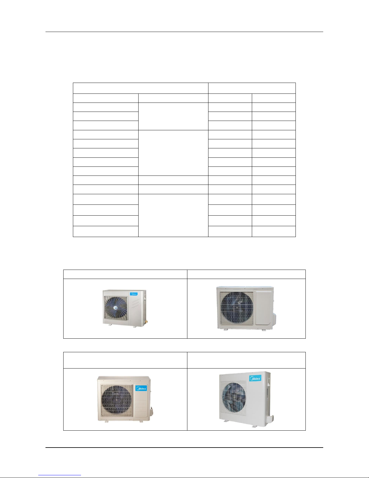
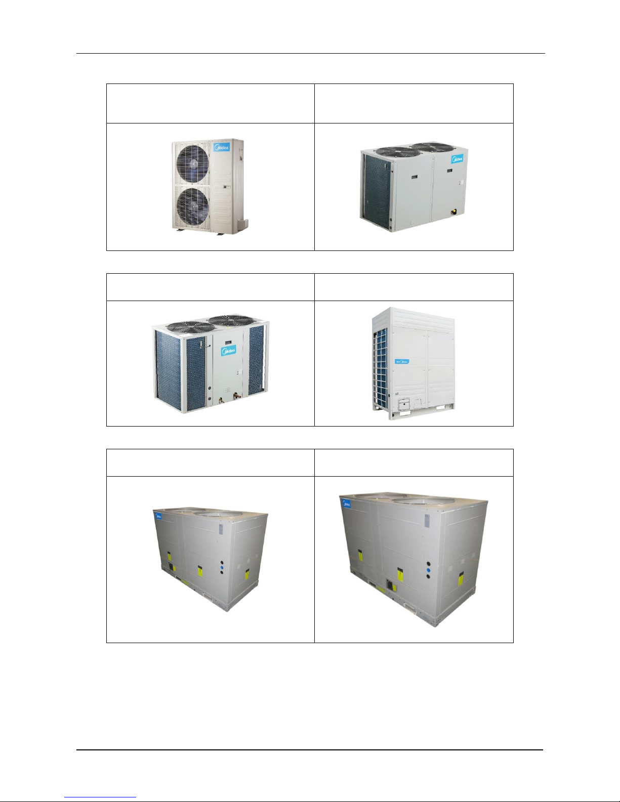
2. External Appearance
MCCU-03CN1
MCCU-05CN1
MCCU-07CN1
MCCU-10CN1
Page 5
Midea R410A 50Hz T1 Compressor Condensing Unit
5
MCCU-12CN1
MCCU-16CN1
MCCU-22CN1
MCCU-28CN1
MCCU-35CN1
MCCU-45CN1
MCCU-53CN1, MCCU-61CN1
MCCU-70CN1, MCCU-105CN1
Page 6
Midea R410A 50Hz T1 Compressor Condensing Unit
6
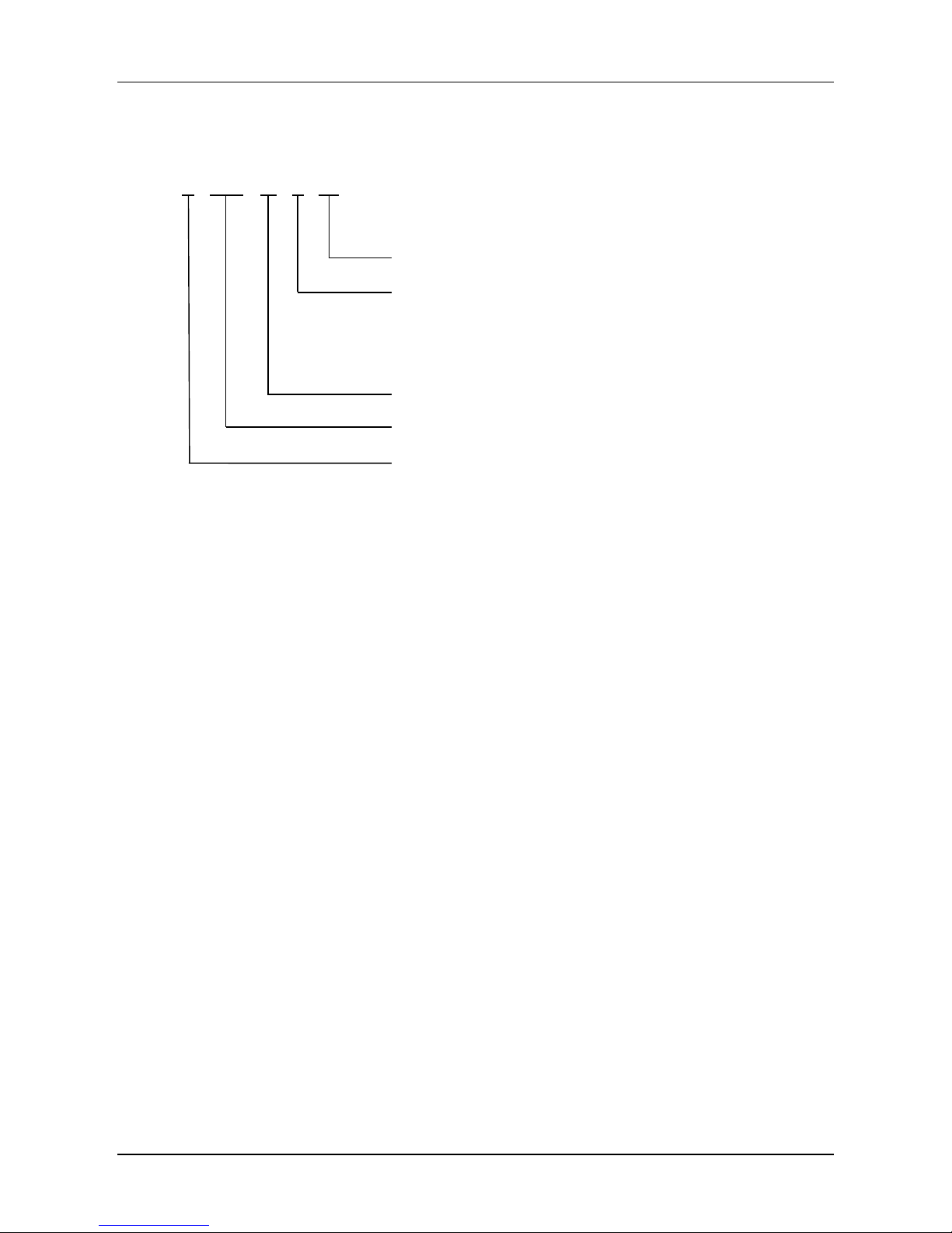
3. Nomenclature
M CCU – 53 C N1
Refrigerant type: R410A
Function code
C: Cooling only
H: Heat pump
Nominal cooling capacity (53×1,000W)
Compressor Condensing Unit
Midea
Page 7
Midea R410A 50Hz T1 Compressor Condensing Unit
7
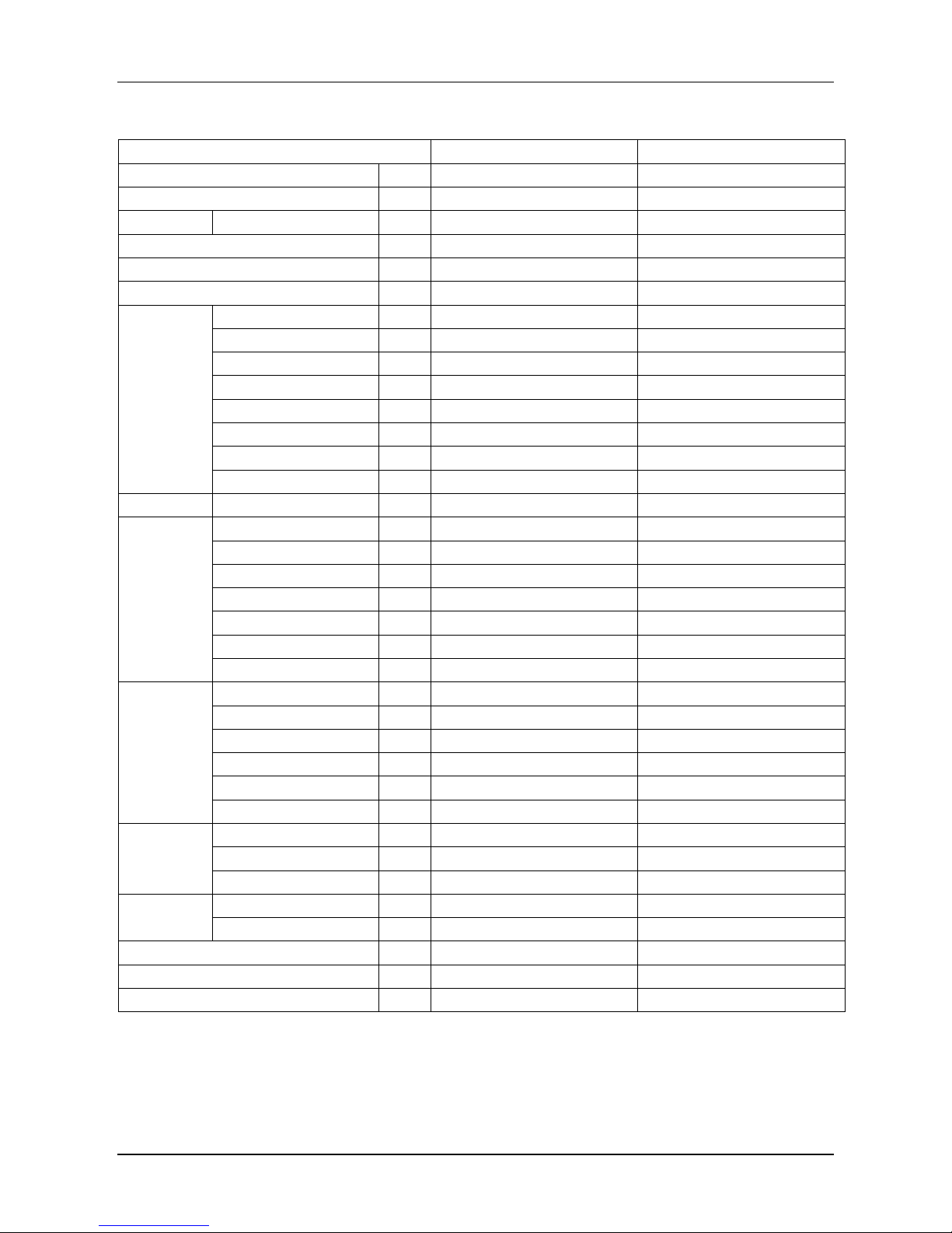
4. Specifications
Model
MCCU-03CN1
MCCU-05CN1
Power supply
\
220-240V~, 1Ph, 50Hz
220-240V~, 1Ph, 50Hz
Ambient temperature range
°C
17~46
17~46
Cooling
Capacity
kW
3.2
5.3
Max. input
kW
1.60
2.85
Max. current A 7.5
15.0
Noise level
dB(A)
29.4
44.0
Compressor
Type / Quantity \ Rotary / 1
Rotary / 1
Model \ PA150X2C-4FT
PA225M2CS-4KU2
Brand
\
GMCC
GMCC
Capacity W 3,660
5,500
Input
W
1,260
1,835
Capacitor \ 35µF/450V
50µF/450V
Rated current (RLA)
A
5.8
8.5
Oil charge \ 480 (Ester oil VG74)
750 (Ester oil VG74)
Refrigerant
Type / Charged
\
R410A / 800g
R410A / 860g
Fan
Type / Quantity
\
Axial fan / 1
Axial fan / 1
Motor model \ YDK24-6F(B)
YDK48-6H(A)
Fan dimension
mm
Φ401
Φ424
Drive type \ Direct
Direct
Capacitor \ 2.5µF/450V
3µF/450V
Motor input W 63
111
Motor speed
rpm
800
890
Coil
Type \ Copper tube and aluminum fin
Copper tube and aluminum fin
Tube size
mm
Φ7.94
Φ7
No. of rows \ 1
2
Fin space
mm
1.6
1.4
Length × Height
mm
762×484
658×546
Number of circuits \ 2
8
Refrigerant
pipe
Liquid side / Gas side
mm
Φ6.35/Φ12.7
Φ6.35/Φ12.7
Max. pipe length m 20
20
Max. difference in level
m
10
10
Connection
wire
Power wire
\
2×2.5mm2+1×1.5mm2 (Ground)
2×4.0mm2+1×2.5mm2 (Ground)
Signal wire \ 1×1.0mm
2
1×1.0mm
2
Dimension (W×H×D)
mm
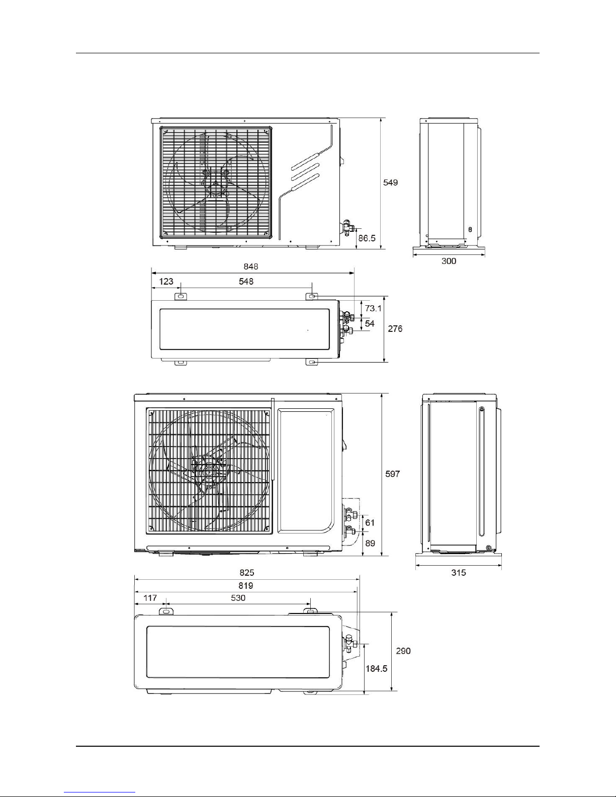
848×549×300
825×597×315
Packing (W×H×D)
mm
910×575×335
890×650×360
Net / Gross weight
kg
30.5/33
36.5/39.5
Notes:
Nominal cooling capacities are based on the following conditions: Indoor temperature: 27°CDB/19°CWB; outdoor
temperature: 35°CDB/24°C WB. Equivalent refrigerant pipe: 7.5m.
Page 8
Midea R410A 50Hz T1 Compressor Condensing Unit
8
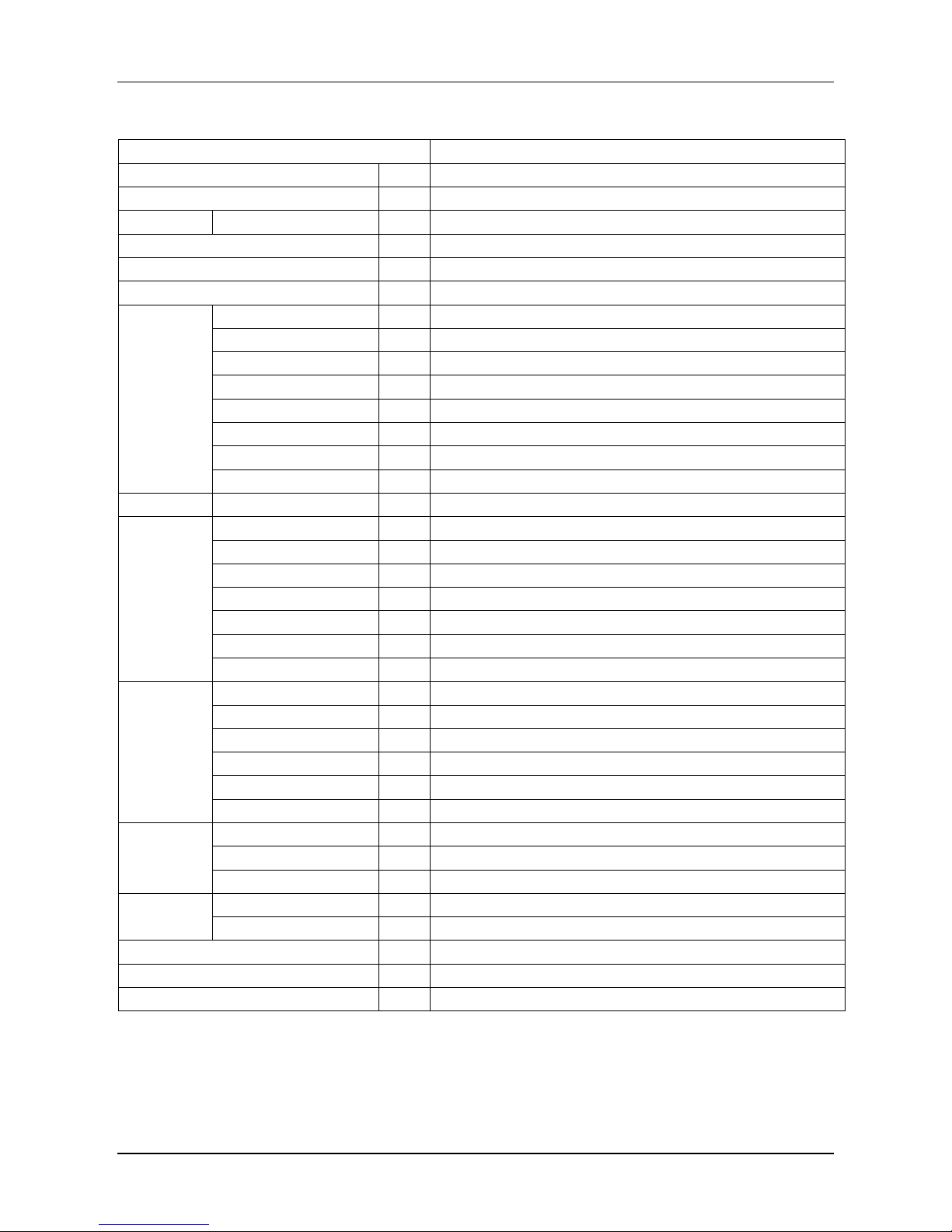
Model
MCCU-07CN1
MCCU-10CN1
Power supply
\
220-240V~, 1Ph, 50Hz
380-415V~, 3Ph, 50Hz
Ambient temperature range
°C
17~46
17~46
Cooling
Capacity
kW
7.1
10.5
Max. input
kW
3.50
5.30
Max. current A 18.0
10
Noise level
dB(A)
72.6
58
Compressor
Type / Quantity \ Rotary / 1
Scroll / 1
Model \ PA290G2CS-4MU1
C-SBN303H8D
Brand
\
GMCC
Sanyo
Capacity W 7,260
9,800
Input
W
2,430
3,650
Capacitor \ 50µF/450V
/
Rated current (RLA)
A
11.65
6.58
Oil charge \ 850 (Ester oil VG74)
1,700 (FV68S)
Refrigerant
Type / Charged
\
R410A / 1,350g
R410A / 2,500g
Fan
Type / Quantity
\
Axial fan / 1
Axial fan / 1
Motor model \ YDK53-6C
YDK190-6D(B)
Fan dimension
mm
Φ460
Φ560
Drive type \ Direct
Direct
Capacitor \ 3µF/450V
10µF/450V
Motor input W 136
290
Motor speed
rpm
800
830
Coil
Type \ Copper tube and aluminum fin
Copper tube and aluminum fin
Tube size
mm
Φ7
Φ7
No. of rows \ 2
1.6
Fin space
mm
1.5
1.5
Length × Height
mm
766×630
898×882
Number of circuits \ 4
7
Refrigerant
pipe
Liquid side / Gas side
mm
Φ9.52/Φ12.7
Φ9.52/Φ19
Max. pipe length m 20
30
Max. difference in level
m
10
20
Connection
wire
Power wire
\
2×6.0mm2+1×4.0mm2 (Ground)
4×4.0mm2+1×2.5mm2 (Ground)
Signal wire \ 1×1.0mm
2
1×1.0mm
2
Dimension (W×H×D)
mm
916×702×360
1,077×967×396
Packing (W×H×D)
mm
965×755×420
1,120×1,100×435
Net / Gross weight
kg
48.5/52
85.8/95.6
Notes:
Nominal cooling capacities are based on the following conditions:
Indoor temperature: 27°CDB, 19°CWB; Outdoor temperature: 35°CDB, 24°C WB; Equivalent refrigerant pipe: 7.5m.
Page 9

Midea R410A 50Hz T1 Compressor Condensing Unit
9
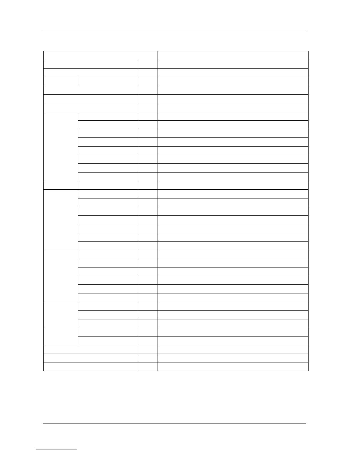
Model
MCCU-12CN1
MCCU-16CN1
Power supply
\
380-415V~, 3Ph, 50Hz
380-415V~, 3Ph, 50Hz
Ambient temperature range
°C
17~46
17~46
Cooling
Capacity
kW
14.0
16.0
Max. input
kW
6.10
8.50
Max. current A 12
13
Noise level
dB(A)
58
59
Compressor
Type / Quantity \ Scroll / 1
Scroll / 1
Model \ C-SBN373H8D
C-SBN453H8D
Brand
\
Sanyo
Sanyo
Capacity W 14,100
16,400
Input
W
4,750
5,750
Capacitor
\
/
/
Rated current (RLA)
A
8.22
9.77
Oil charge \ 1,700 (FV68S)
1,700 (FV68S)
Refrigerant
Type / Charged
\
R410A / 3,000g
R410A / 3,050g
Fan
Type / Quantity
\
Axial fan / 2
Axial fan / 2
Motor model \ YDK65-6F(B)
YDK65-6F(B)
Fan dimension
mm
Φ455
Φ455
Drive type \ Direct
Direct
Capacitor \ 4µF/450V
4µF/450V
Motor input W 174
174
Motor speed
rpm
825
825
Coil
Type \ Copper tube and aluminum fin
Copper tube and aluminum fin
Tube size
mm
Φ7
Φ7.94
No. of rows \ 2
2
Fin space
mm
1.5
1.6
Length × Height
mm
845×1,092
837×1,100
Number of circuits \ 8
8
Refrigerant
pipe
Liquid side / Gas side
mm
Φ9.52/Φ19
Φ9.52/Φ19
Max. pipe length m 30
30
Max. difference in level
m
20
20
Connection
wire
Power wire
\
4×4.0mm2+1×2.5mm2 (Ground)
4×10.0mm2+1×6.0mm2 (Ground)
Signal wire \ 1×1.0mm
2
1×1.0mm
2
Dimension (W×H×D)
mm
987×1,167×400
987×1,167×400
Packing (W×H×D)
mm
1,032×1,307×443
1,032×1,307×443
Net / Gross weight
kg
91.6/102
96.6/107
Notes:
Nominal cooling capacities are based on the following conditions:
Indoor temperature: 27°CDB, 19°CWB; Outdoor temperature: 35°CDB, 24°C WB; Equivalent refrigerant pipe: 7.5m.
Page 10
Midea R410A 50Hz T1 Compressor Condensing Unit
10
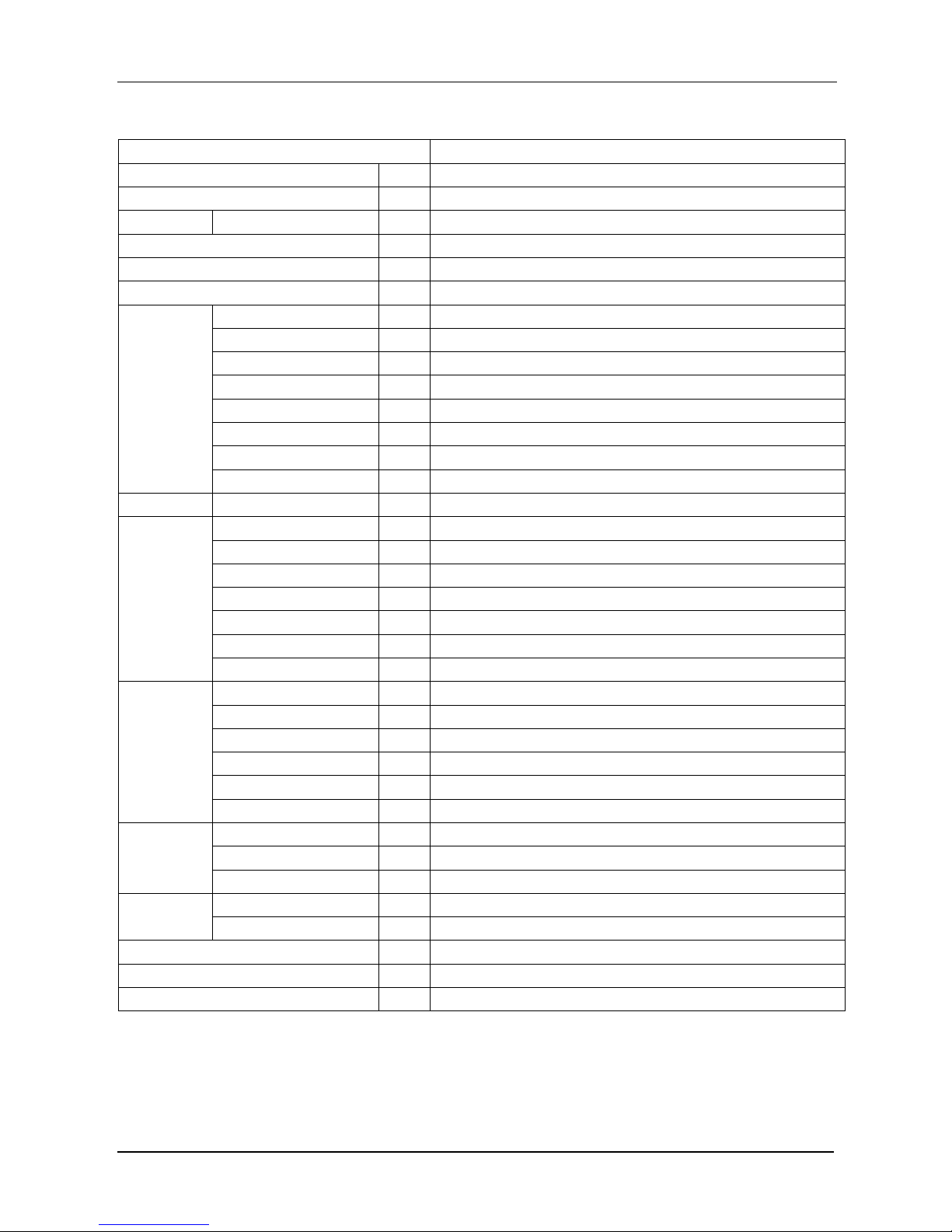
Model
MCCU-22CN1
Power supply
\
380-415V~, 3Ph, 50Hz
Ambient temperature range
°C
17~52
Cooling
Capacity
kW
22.0
Max. input
kW
11.70
Max. current
A
19.3
Noise level
dB(A)
65
Compressor
Type / Quantity
\
Scroll / 1
Model
\
ZP90KCE-TFD-522
Brand
\
Copeland
Capacity
W
21,900
Input
W
6,950
Capacitor
\ / Rated current (RLA)
A
16.5
Oil charge
\
2,513 (POE)
Refrigerant
Type / Charged
\
R410A / 5,400g
Fan
Type / Quantity
\
Axial fan / 2
Motor model
\
YDK210-6A
Fan dimension
mm
Φ530
Drive type
\
Direct
Capacitor
\
10μF/450V
Motor input
W
Hi: 284; Lo: 202
Motor speed
rpm
Hi: 920/930; Lo: 650/710 (4 blades/3 blades)
Coil
Type
\
Copper tube and aluminum fin
Tube size
mm
Ф7.94
No. of rows
\ 2 Fin space
mm
1.4
Length × Height
mm
2,177×880
Number of circuits
\
9
Refrigerant
pipe
Liquid side / Gas side
mm
Ф9.52/Ф22
Max. pipe length
m
50
Max. difference in level
m
30
Connection
wire
Power wire
\
5×6.0mm
2
Signal wire
\
2×1.0mm
2
Dimension (W×H×D)
mm
1,260×908×700
Packing (W×H×D)
mm
1,320×1,060×730
Net / Gross weight
kg
171/190
Notes:
Nominal cooling capacities are based on the following conditions:
Indoor temperature: 27°CDB, 19°CWB; Outdoor temperature: 35°CDB, 24°C WB; Equivalent refrigerant pipe: 7.5m.
Page 11

Midea R410A 50Hz T1 Compressor Condensing Unit
11
Model
MCCU-28CN1
Power supply
\
380-415V~, 3Ph, 50Hz
Ambient temperature range
°C
17~52
Cooling
Capacity
kW
28.0
Max. input
kW
14.40
Max. current
A
23.7
Noise level
dB(A)
67
Compressor
Type / Quantity
\
Scroll / 1
Model
\
ZP120KCE-TFD-522
Brand
\
Copeland
Capacity
W
29,200
Input
W
9,200
Capacitor
\ / Rated current (RLA)
A
20
Oil charge
\
3,253 (POE)
Refrigerant
Type / Charged
\
R410A / 6,000g
Fan
Type / Quantity
\
Axial fan / 2
Motor model
\
YDK400-4C
Fan dimension
mm
Φ530
Drive type
\
Direct
Capacitor
\
25μF/450V
Motor input W Hi: 621/587; Lo: 388/388 (4 blades/3 blades)
Motor speed
rpm
Hi: 1,180/1,230; Lo: 790/870 (4 blades/3 blades)
Coil
Type
\
Copper tube and aluminum fin
Tube size
mm
Ф7
No. of rows
\ 3 Fin space
mm
1.3
Length × Height
mm
2,179×882
Number of circuits
\
20
Refrigerant
pipe
Liquid side / Gas side
mm
Ф9.52/Ф25
Max. pipe length
m
50
Max. difference in level
m
30
Connection
wire
Power wire
\
5×6.0mm
2
Signal wire
\
2×1.0mm
2
Dimension (W×H×D)
mm
1,260×908×700
Packing (W×H×D)
mm
1,320×1,060×730
Net / Gross weight
kg
185/202
Notes:
Nominal cooling capacities are based on the following conditions:
Indoor temperature: 27°CDB, 19°CWB; Outdoor temperature: 35°CDB, 24°C WB; Equivalent refrigerant pipe: 7.5m.
Page 12
Midea R410A 50Hz T1 Compressor Condensing Unit
12
Model
MCCU-35CN1
Power supply
\
380-400V~, 3Ph, 50Hz
Ambient temperature range
°C
17~52
Cooling
Capacity
kW
35.0
Max. input
kW
17.30
Max. current
A
28.5
Noise level
dB(A)
69
Compressor
Type / Quantity
\
Scroll / 1
Model
\
SH140A4ALC
Brand
\
Danfoss
Capacity
W
34,700
Input
W
10,862
Capacitor
\ / Rated current (RLA)
A
21.4
Oil charge
\
3,300 (POE-160SZ)
Refrigerant
Type / Charged
\
R410A / 7,200g
Fan
Type / Quantity
\
Axial fan / 2
Motor model
\
YDK400-4C
Fan dimension
mm
Φ530
Drive type
\
Direct
Capacitor
\
25μF/450V
Motor input W Hi: 621/587; Lo: 388/388 (4 blades/3 blades)
Motor speed
rpm
Hi: 1,180/1,230; Lo: 790/870 (4 blades/3 blades)
Coil
Type
\
Copper tube and aluminum fin
Tube size
mm
Ф7
No. of rows
\ 3 Fin space
mm
1.3
Length × Height
mm
(1,380×882)+(1,380×882)
Number of circuits
\
20+20
Refrigerant
pipe
Liquid side / Gas side
mm
Ф12.7/Ф28.6
Max. pipe length
m
50
Max. difference in level
m
30
Connection
wire
Power wire
\
5×6.0mm
2
Signal wire
\
2×1.0mm
2
Dimension (W×H×D)
mm
1,260×908×700
Packing (W×H×D)
mm
1,320×1,060×730
Net / Gross weight
kg
199/215
Notes:
Nominal cooling capacities are based on the following conditions:
Indoor temperature: 27°CDB, 19°CWB; Outdoor temperature: 35°CDB, 24°C WB; Equivalent refrigerant pipe: 7.5m.
Page 13

Midea R410A 50Hz T1 Compressor Condensing Unit
13
Model
MCCU-45CN1
Power supply
\
380-415V~, 3Ph, 50Hz
Ambient temperature range
°C
17~46
Cooling
Capacity
kW
45.0
Max. input
kW
26.90
Max. current
A
47.9
Noise level
dB(A)
70
Compressor
Type / Quantity
\
Scroll / 3
Model
\
E605DH-59D2YG
Brand
\
Hitachi
Capacity
W
15,390
Input
W
5,130
Capacitor
\ / Rated current (RLA)
A
8.8
Oil charge
\
500 (FVC68D)
Refrigerant
Type / Charged
\
R410A / 10,000g
Fan
Type / Quantity
\
Axial fan / 2
Motor model
\
YDK380-4D
Fan dimension
mm
Φ560/Φ562
Drive type
\
Direct
Capacitor
\
20μF/450V
Motor input W Hi: 615/580; Lo: 425/420 (4 blades/3 blades)
Motor speed
rpm
Hi: 1,000/1,090; Lo: 780/870 (4 blades/3 blades)
Coil
Type
\
Copper tube and aluminum fin
Tube size
mm
Ф7.94
No. of rows
\ 2 Fin space
mm
1.6
Length × Height
mm
2,286×1,232
Number of circuits
\
28
Refrigerant
pipe
Liquid side / Gas side
mm
Ф16/Ф32
Max. pipe length
m
50
Max. difference in level
m
30
Connection
wire
Power wire
\
5×15.0mm
2
Signal wire
\
2×1.0mm
2
Dimension (W×H×D)
mm
1,250×1,615×765
Packing (W×H×D)
mm
1,305×1,790×820
Net / Gross weight
kg
288/308
Notes:
Nominal cooling capacities are based on the following conditions:
Indoor temperature: 27°CDB, 19°CWB; Outdoor temperature: 35°CDB, 24°C WB; Equivalent refrigerant pipe: 7.5m.
Page 14

Midea R410A 50Hz T1 Compressor Condensing Unit
14
Model
MCCU-53CN1
Power supply
\
380-400V~, 3Ph, 50Hz
Ambient temperature range
°C
18~46
Cooling
Capacity
kW
53.0
Max. input
kW
23.70
Max. current
A
45.2
Noise level
dB(A)
73
Compressor
Type / Quantity
\
Scroll / 2
Model
\
SH105A4ALC
Brand
\
Danfoss
Capacity
W
26,816
Input
W
8,472
Capacitor
\ / Rated current (RLA)
A
16.4
Oil charge
\
3,300ml (POE-160SZ)
Refrigerant
Type / Charged
\
R410A / 11,000g
Fan
Type / Quantity
\
Axial fan / 2
Motor model
\
YS600-6P
Fan dimension
mm
Φ650
Drive type
\
Direct
Capacitor
\ \ Motor input
W
750
Motor speed
rpm
930
Coil
Type
\
Copper tube and aluminum fin
Tube size
mm
Φ7.94
No. of rows
\ 3 Fin space
mm
1.6
Length × Height
mm
2,209×1,100
Number of circuits
\
12+12
Refrigerant
pipe
Liquid side / Gas side
mm
(Ф12.7/Ф25)×2
Max. pipe length
m
50
Max. difference in level
m
30
Connection
wire
Power wire \ 4×16.0mm2+1×10.0mm2 (Ground)
Signal wire
\
2×1.0mm
2
Dimension (W×H×D)
mm
1,825×1,245×899
Packing (W×H×D)
mm
1,844×1,272×924
Net / Gross weight
kg
395/405
Notes:
Nominal cooling capacities are based on the following conditions:
Indoor temperature: 27°CDB, 19°CWB; Outdoor temperature: 35°CDB, 24°C WB; Equivalent refrigerant pipe: 7.5m.
Page 15

Midea R410A 50Hz T1 Compressor Condensing Unit
15
Model
MCCU-61CN1
Power supply
\
380-400V~, 3Ph, 50Hz
Ambient temp range
°C
17~46
Cooling
Capacity
kW
61.0
Max. input
kW
28.20
Max. current
A
51.0
Noise level
dB(A)
76
Compressor
Type / Quantity
\
Scroll / 2
Model
\
SH120A4ALC
Brand
\
Danfoss
Capacity
W
29,950
Input
W
9,462
Capacitor
\ / Rated current (RLA)
A
20.7
Oil charge
\
3,300ml (POE-160SZ)
Refrigerant
Type / Charged
\
R410A / 12,400g
Fan
Type / Quantity
\
Axial fan / 2
Motor model
\
YS1100-6
Fan dimension
mm
Φ700
Drive type
\
Direct
Capacitor
\ \ Motor input
W
1,300
Motor speed
rpm
940
Coil
Type
\
Copper tube and aluminum fin
Tube size
mm
Φ7.94
No. of rows
\ 3 Fin space
mm
1.6
Length × Height
mm
2,209×1,100
Number of circuits
\
12+12
Refrigerant
pipe
Liquid side / Gas side
mm
(Ф12.7/Ф25)×2
Max. pipe length
m
50
Max. difference in level
m
30
Connection
wire
Power wire
\
4×25.0mm2+1×16.0mm2 (Ground)
Signal wire
\
2×1.0mm
2
Dimension (W×H×D)
mm
1,825×1,245×899
Packing (W×H×D)
mm
1,844×1,272×924
Net / Gross weight
kg
395/405
Notes:
Nominal cooling capacities are based on the following conditions:
Indoor temperature: 27°CDB, 19°CWB; Outdoor temperature: 35°CDB, 24°C WB; Equivalent refrigerant pipe: 7.5m.
Page 16

Midea R410A 50Hz T1 Compressor Condensing Unit
16
Model
MCCU-70CN1
Power supply
\
380-400V~, 3Ph, 50Hz
Ambient temperature range
°C
17~46
Cooling
Capacity
kW
70.0
Max. input
kW
31.80
Max. current
A
56.5
Noise level
dB(A)
76
Compressor
Type / Quantity
\
Scroll / 2
Model
\
SH140A4ALC
Brand
\
Danfoss
Capacity
W
34,700
Input
W
10,862
Capacitor
\ / Rated current (RLA)
A
21.4
Oil charge
\
3,300ml (POE-160SZ)
Refrigerant
Type / Charged
\
R410A / 17,000
Fan
Type / Quantity
\
Axial fan / 2
Motor model
\
YS1100-6
Fan dimension
mm
Φ750
Drive type
\
Direct
Capacitor
\ \ Motor input
W
1,300
Motor speed
rpm
940
Coil
Type
\
Copper tube and aluminum fin
Tube size
mm
Φ7.94
No. of rows
\
3.6
Fin space
mm
1.6
Length × Height
mm
(1,355×1,100)+(1,325×1,100)
Number of circuits
\
25+25
Refrigerant
pipe
Liquid side / Gas side
mm
(Ф12.7/Ф25)×2
Max. pipe length
m
50
Max. difference in level
m
30
Connection
wire
Power wire
\
4×25.0mm2+1×16.0mm2 (Ground)
Signal wire
\
2×1.0mm
2
Dimension (W×H×D)
mm
2,158×1,258×1,082
Packing (W×H×D)
mm
2,168×1,275×1,105
Net / Gross weight
kg
508/523
Notes:
Nominal cooling capacities are based on the following conditions:
Indoor temperature: 27°CDB, 19°CWB; Outdoor temperature: 35°CDB, 24°C WB; Equivalent refrigerant pipe: 7.5m.
Page 17
Midea R410A 50Hz T1 Compressor Condensing Unit
17
Model
MCCU-105CN1
Power supply
\
380-400V~, 3Ph, 50Hz
Ambient temp range
°C
17~46
Cooling
Capacity
kW
105.0
Max. input
kW
40.70
Max. current
A
71.8
Noise level
dB(A)
78
Compressor
Type / Quantity
\
Scroll / 2
Model
\
SH184A4ALC
Brand
\
Danfoss
Capacity
W
44,661
Input
W
13,732
Capacitor
\ / Rated current (RLA)
A
27.6
Oil charge
\
3,600ml (POE-160SZ)
Refrigerant
Type / Charged
\
R410A / 18,000g
Fan
Type / Quantity
\
Axial fan / 2
Motor model
\
YS1500-6
Fan dimension
mm
Φ802
Drive type
\
Direct
Capacitor
\ \ Motor input
W
1,690
Motor speed
rpm
910
Coil
Type
\
Copper tube and aluminum fin
Tube size
mm
Φ7
No. of rows
\
3.6
Fin space
mm
1.5
Length × Height
mm
(1,325×756)×2+(1367×756)×2
Number of circuits
\
24+24
Refrigerant
pipe
Liquid side / Gas side
mm
(Ф12.7/Ф25)×2
Max. pipe length
m
50
Max. difference in level
m
30
Connection
wire
Power wire
\
4×35.0mm2+1×16.0mm2 (Ground)
Signal wire
\
2×1.0mm
2
Dimension (W×H×D)
mm
2,158×1,669×1,082
Packing (W×H×D)
mm
2,168×1,686×1,105
Net/ Gross weight
kg
570/582
Notes:
Nominal cooling capacities are based on the following conditions:
Indoor temperature: 27°CDB, 19°CWB; Outdoor temperature: 35°CDB, 24°C WB; Equivalent refrigerant pipe: 7.5m.
Page 18
Midea R410A 50Hz T1 Compressor Condensing Unit
18
5. Dimensions (Unit: mm)
MCCU-03CN1
MCCU-05CN1
Page 19

Midea R410A 50Hz T1 Compressor Condensing Unit
19
MCCU-07CN1
MCCU-10CN1
Page 20
Midea R410A 50Hz T1 Compressor Condensing Unit
20
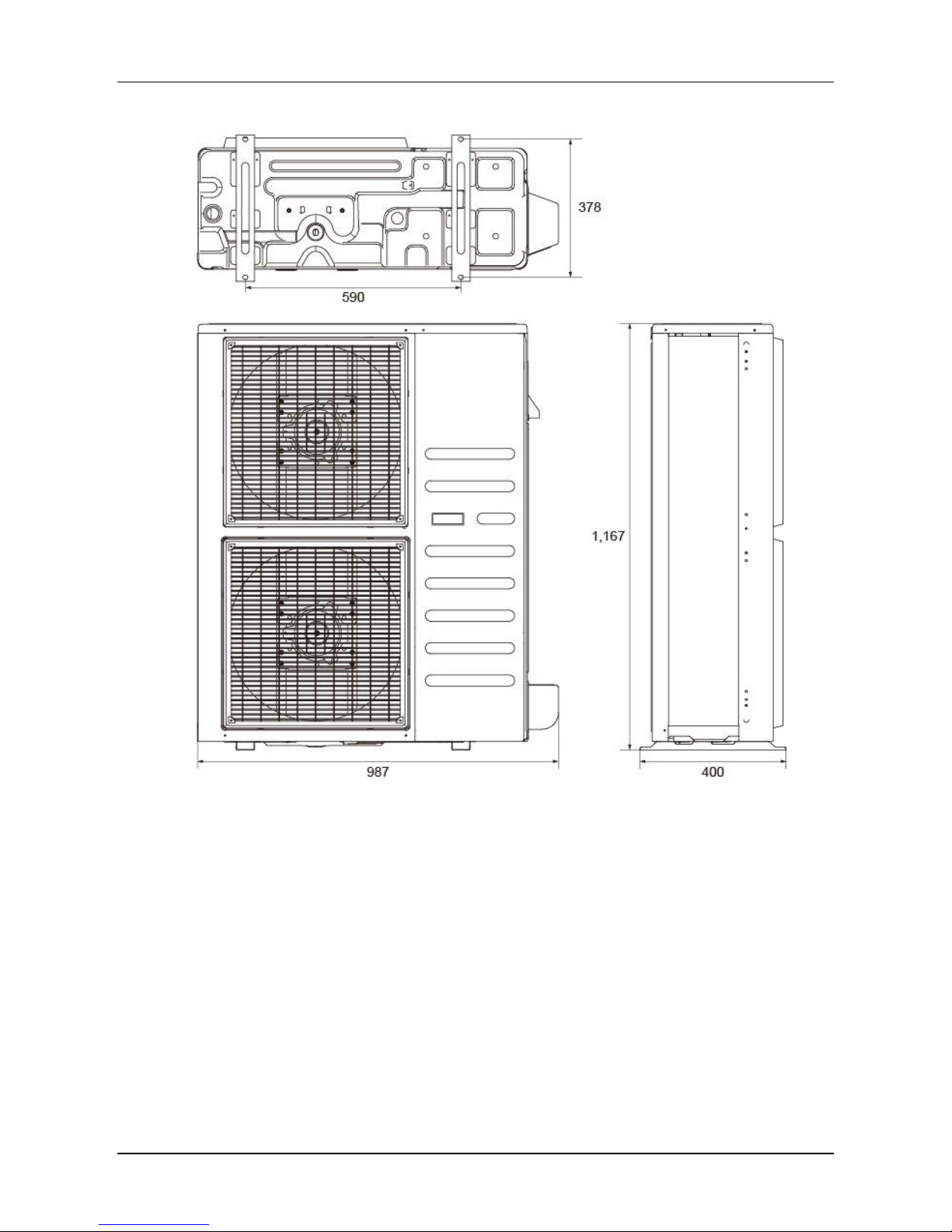
MCCU-12CN1, MCCU-16CN1
Page 21
Midea R410A 50Hz T1 Compressor Condensing Unit
21
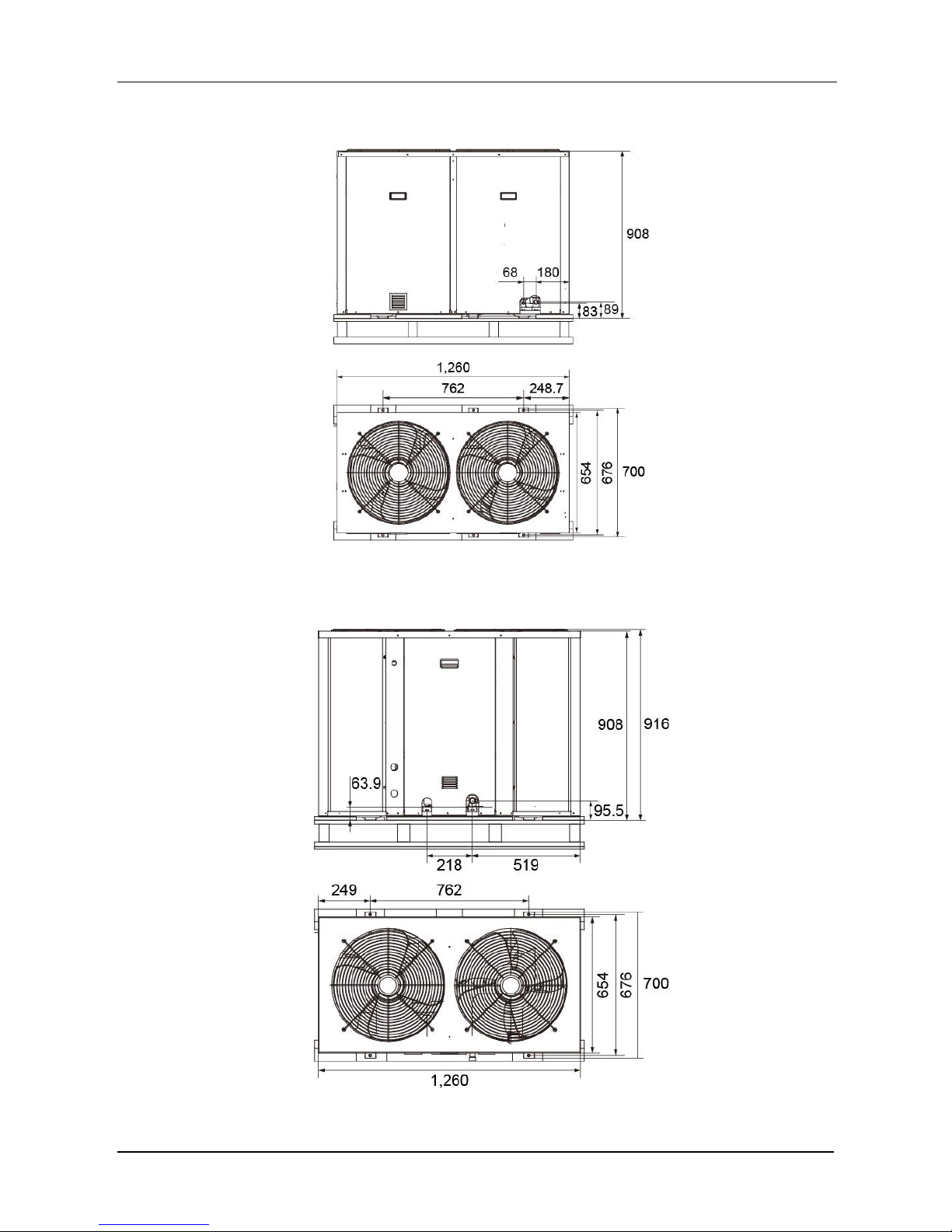
MCCU-22CN1, MCCU-28CN1
MCCU-35CN1
Page 22

Midea R410A 50Hz T1 Compressor Condensing Unit
22
MCCU-45CN1
MCCU-53CN1, MCCU-61CN1
Page 23

Midea R410A 50Hz T1 Compressor Condensing Unit
23
MCCU-70CN1
MCCU-105CN1
Page 24

Midea R410A 50Hz T1 Compressor Condensing Unit
24
6. Refrigerant circuits
MCCU-03CN1, MCCU-05CN1, MCCU-07CN1
Page 25

Midea R410A 50Hz T1 Compressor Condensing Unit
25
MCCU-10CN1, MCCU-12CN1, MCCU-16CN1, MCCU-22CN1, MCCU-28CN1, MCCU-35CN1
Page 26

Midea R410A 50Hz T1 Compressor Condensing Unit
26
MCCU-45CN1
Page 27

Midea R410A 50Hz T1 Compressor Condensing Unit
27
MCCU-53CN1, MCCU-61CN1, MCCU-70CN1, MCCU-105CN1
Notes: Two 4-way valves connected in refrigerant pipe systems are invalid.
Page 28

Midea R410A 50Hz T1 Compressor Condensing Unit
28
7. Wiring Diagrams
MCCU-03CN1, MCCU-05CN1
MCCU-07CN1
Page 29

Midea R410A 50Hz T1 Compressor Condensing Unit
29
MCCU-10CN1
MCCU-12CN1
Page 30

Midea R410A 50Hz T1 Compressor Condensing Unit
30
MCCU-22CN1, MCCU-28CN1, MCCU-35CN1
Page 31

Midea R410A 50Hz T1 Compressor Condensing Unit
31
MCCU-45CN1
Page 32

Midea R410A 50Hz T1 Compressor Condensing Unit
32
MCCU-53CN1, MCCU-61CN1, MCCU-70CN1
Page 33

Midea R410A 50Hz T1 Compressor Condensing Unit
33
MCCU-105CN1
Page 34

Midea R410A 50Hz T1 Compressor Condensing Unit
34
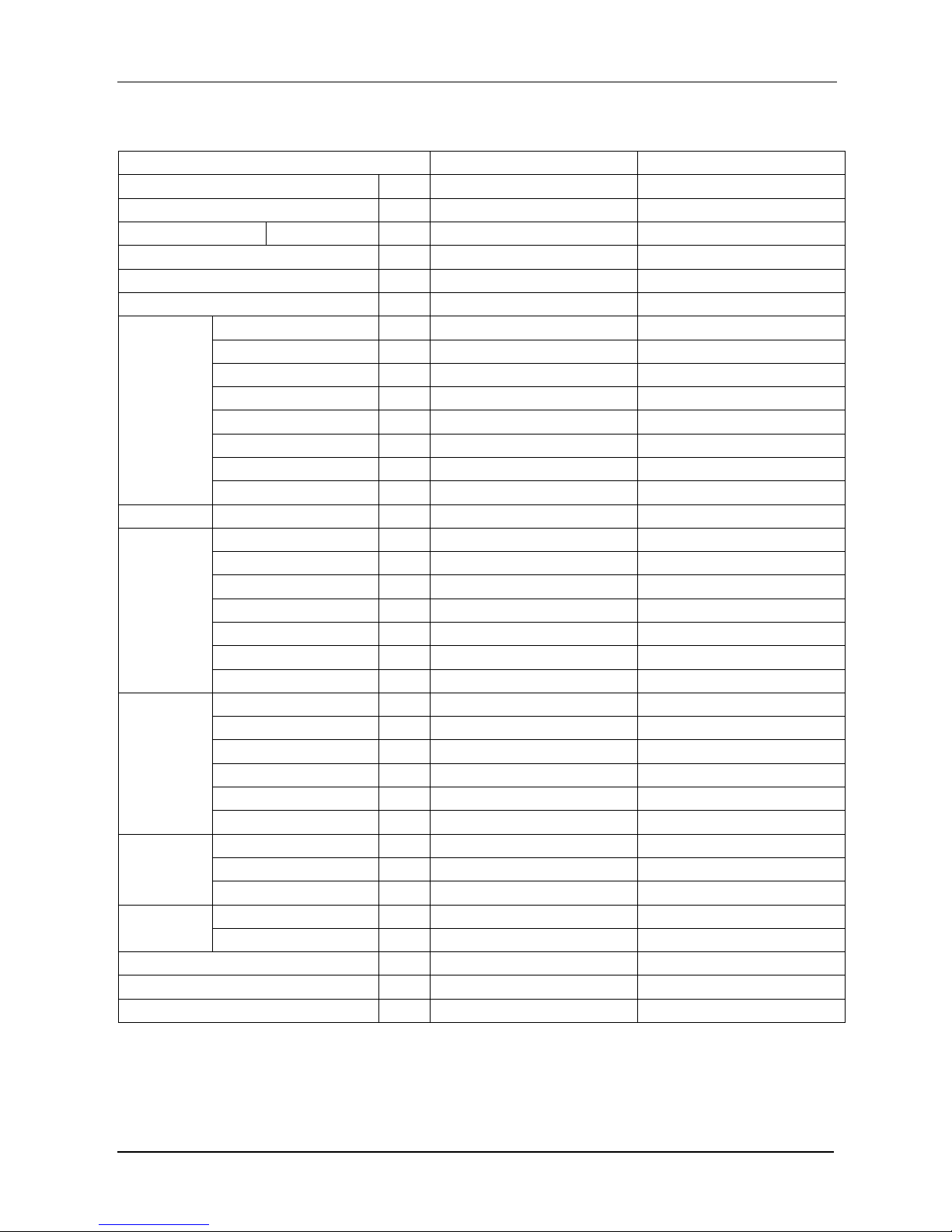
8. Electrical datas
Model
Whole units
Power Supply
Compressor
OFM
Hz
Voltage
Min.
Max.
MCA
TOCA
MFA
MSC
RLA
kW
FLA
MCCU-03CN1
50
220~240V
198V
254V
7.8
8.6
20.0
29.9
5.8
0.024
0.28
MCCU-05CN1
50
220~240V
198V
254V
11.5
15.2
40.0
40.0
8.5
0.048
0.49
MCCU-07CN1
50
220~240V
198V
254V
17.0
18.7
60.0
66.0
12.6
0.053
0.61
MCCU-10CN1
50
380~415V
342V
440V
9.2
9.4
20
52
6.58
0.19
1.31
MCCU-12CN1
50
380~415V
342V
440V
10.8
10.9
25
66
8.2
0.13
1.6
MCCU-16CN1
50
380~415V
342V
440V
12.6
15.2
35
67
9.7
0.13
1.6
MCCU-22CN1
50
380~415V
342V
440V
17.5
18
20.5
86
16.5
0.573
2.613
MCCU-28CN1
50
380~415V
342V
440V
20
21
23.8
110
20
1.373
6.26
MCCU-35CN1
50
380~400V
342V
440V
25
28.6
30
147
21.4
0.604
2.93
MCCU-45CN1
50
380~415V
342V
440V
37.1
47.9
52.7
62
8.8
0.76
5.48
MCCU-53CN1
50
380~400V
342V
440V
49.6
54.8
60.3
142
16.4
1.2 4 MCCU-61CN1
50
380~400V
342V
440V
67.5
66.8
73.5
142
20.7
2.2
5.4
MCCU-70CN1
50
380~400V
342V
440V
69.2
70.8
77.9
147
21.4
2.2
5.2
MCCU-105CN1
50
380~400V
342V
440V
90.5
87.2
95.9
197
27.6 3 6.6
Notes:
MCA: Min. Current Amps. (A) TOCA : Total Over-current Amps. (A)
MFA: Max. Fuse Amps. (A) MSC: Max. Starting Amps. (A)
RLA: Rated Locked Amps. (A) OFM: Outdoor Fan Motor
kW: Fan Motor Rated Output (kW) FLA: Full Load Amps. (A)
9. Sound Levels
Model
Noise level
MCCU-03CN1
65 dB(A)
MCCU-05CN1
67 dB(A)
MCCU-07CN1
69 dB(A)
MCCU-10CN1
70 dB(A)
MCCU-12CN1
73 dB(A)
MCCU-16CN1
76 dB(A)
Page 35

Midea R410A 50Hz T1 Compressor Condensing Unit
35
Front
h
H
1 m
Model
Noise level
MCCU-22CN1
65 dB(A)
MCCU-28CN1
67 dB(A)
MCCU-35CN1
69 dB(A)
MCCU-45CN1
70 dB(A)
MCCU-53CN1
73 dB(A)
MCCU-61CN1
76 dB(A)
MCCU-70CN1
76 dB(A)
MCCU-105CN1
78 dB(A)
Notes:
1. H=(h+1)/2m.
2. The sound pressure value is the weighted average of four sides which include front, rear, left and right
side of the unit.
10. Connection accessory list (Optional)
CCU-10N1(C)
CCU-11N1(C)
CCU-01N1(C)
Available CCU model
MCCU-03CN1
MCCU-05CN1
MCCU-07CN1
Thermal expansion
valve
Model
BAE 1 ZW195
BAE 1-1/2 ZW195
BAE 2 ZW195
Quantity 1 1
1
Filter drier
Model
DML032S 023Z5048
DML032S 023Z5048
DML033S 023Z5050
Quantity 1 1
1
Sight glasses
Model
SGP 6sN(014L0181)
SGP 6sN(014L0181)
SGP 10sN(014L0182)
Quantity 1 1
1
Electromagnetic valve
Model
EVR3-1/4-032F1206
EVR3-1/4-032F1206
EVR3 (032F1204)
Quantity 1 1
1
Electromagnetic valve
solenoid
Model
DCFXQ-018F6905
DCFXQ-018F6905
DCFXQ-018F6905
Quantity 1 1
1
Package size (mm)
400×215×290
400×215×290
400×215×290
Page 36

Midea R410A 50Hz T1 Compressor Condensing Unit
36
CCU-02N1(C)
CCU-03N1(C)
CCU-04N1(C)
Available CCU model
MCCU-10CN1
MCCU-12CN1
MCCU-16CN1
Thermal expansion
valve
Model
BAE 3 ZW195
TGEL4.5 067N3172
TGEL4.5 067N3172
Quantity 1 1
1
Filter drier
Model
DML033S 023Z5050
DML053S 023Z5054
DML053S 023Z5054
Quantity 1 1
1
Sight glasses
Model
SGP 10sN(014L0182)
SGP 10sN(014L0182)
SGP 10sN(014L0182)
Quantity 1 1
1
Electromagnetic valve
Model
EVR6 (032F1212)
EVR6 (032F1212)
EVR6 (032F1212)
Quantity 1 1
1
Electromagnetic valve
solenoid
Model
DCFXQ-018F6905
DCFXQ-018F6905
DCFXQ-018F6905
Quantity 1 1
1
Package size (mm)
400×215×290
400×215×290
400×215×290
CCU-05N1(C)
CCU-06N1(C)
CCU-07N1(C)
Available CCU model
MCCU-22CN1
MCCU-28CN1
MCCU-35CN1
Thermal expansion
valve
Model
TGEL6.5 067N3174
TGEL9 067N3176
TGEL13 067N3177
Quantity 1 1
1
Filter drier
Model
DML083S 023Z5058
GZGLQ-DML164S
GZGLQ-DML164S
Quantity 1 1
1
Sight glasses
Model
SGP 10sN(014L0182)
SGP 12sN(014L0183)
SGP 12sN(014L0183)
Quantity 1 1
1
Electromagnetic valve
Model
EVR6 (032F1212)
EVRH10 (032G1054)
EVRH10 (032G1054 )
Quantity 1 1
1
Electromagnetic valve
solenoid
Model
DCFXQ-018F6905
DCFXQ-018F6905
DCFXQ-018F6905
Quantity 1 1
1
Package size (mm)
400×215×290
400×215×290
400×215×290
CCU-08N1(C)
T-KF530W/RN1.7
Available CCU model
MCCU-45CN1
MCCU-53CN1
MCCU-61CN1
Thermal expansion
valve
Model
TGEL13 067N3177
TGEL9 067N3176
TGEL9 067N3176
Quantity 1 2
2
Filter drier
Model
GZGLQ-DML165S
DML 305 FS
DML 305 FS
Quantity 1 2
2
Sight glasses
Model
SGP 16sI(014L0044)
SGP 12sN(014L0183)
SGP 12sN(014L0183)
Quantity 1 2
2
Electromagnetic valve
Model
EVRH15(032G1056)
EVR10(032F1217)
EVR10(032F1217)
Quantity 1 2
2
Electromagnetic valve
solenoid
Model
DCFXQ-018F6905
018F6251
018F6251
Quantity 1 2
2
Package size (mm)
400×215×290
290×265×226
290×265×226
Page 37

Midea R410A 50Hz T1 Compressor Condensing Unit
37
T-KF700W/RN1.11 T-KF1050W/RN1.8
Available CCU model
MCCU-70CN1
MCCU-105CN1
Thermal expansion
valve
Model
TGEL13 067N3177
TGEL15 067N3159
Quantity
2
2
Filter drier
Model
DML 305 FS
DML 305 FS
Quantity
2
2
Sight glasses
Model
SGP 12sN(014L0183)
SGP 16sN(014L0184)
Quantity
2
2
Electromagnetic valve
Model
EVR10(032F1217)
EVR10(032F1217)
Quantity
2
2
Electromagnetic valve
solenoid
Model
018F6251
018F6251
Quantity
2
2
Package size (mm)
290×265×226
290×265×226
Page 38

Midea R410A 50Hz T1 Compressor Condensing Unit
38
Part. 2 Installation
1. Notes ............................................................................ 39
2. Transport and Fixed units ......................................... 40
3. Connection of Refrigerant Pipe ................................ 43
4. Heat Insulation of Refrigerant Pipe .......................... 54
5. Electric Connection .................................................... 54
6. Trial Run ...................................................................... 56
7. Trouble shooting ........................................................ 57
8. Maintenance ................................................................ 65
Page 39

Midea R410A 50Hz T1 Compressor Condensing Unit
39
1. Notes
CAUTION:
Install the unit where enough space of installation and maintenance is available.
Install the unit where the air inlet and outlet are not baffled and the least affected by external air.
Install the unit where it is easy to lead out the connective pipe and the drain pipe.
Install the unit where no heat is emitted from a heat source directly.
Installing the equipment in any of the following places may lead to faults of the equipment (if that
is inevitable, consult the supplier):
The site contains mineral oils such as cutting lubricant.
Seaside where the air contains much salt.
Hot ring area where corrosive gases exist, e.g., sulfide gas.
Factories where the supply voltage fluctuates seriously.
Inside a car or cabin.
Place like kitchen where oil permeates.
Place where strong electromagnetic waves exist.
Place where flammable gases or materials exist.
Place where acid or alkali gases evaporate, or other special environments.
Install the unit where enough space of installation and maintenance is available.
Install the unit where the air inlet and air outlet are free from obstacles and strong wind.
Install the unit in a dry and well ventilated place.
For side-discharge outdoor unit, the air outlet and inlet are not impeded, and cannot be reached
by strong wind.
Install the unit where the bearing surface is level and can bear weight of the unit, and is suitable
Page 40

Midea R410A 50Hz T1 Compressor Condensing Unit
40
for installing the unit horizontally without increasing noise or vibration.
Install the unit where the operation noise and the expelling of air do not affect neighbors.
Install the unit where no flammable gas is leaked.
Install the unit where it is convenient for pipe connection and electric connection.
2. Transport and Fixed units
When installing the unit, leave a space for maintenance shown in the following figure. Install the
power supply at the side of the outdoor unit.
MCCU-03CN1, MCCU-05CN1, MCCU-07CN1, MCCU-10CN1, MCCU-12CN1, MCCU-16CN1:
In case any obstacles exist above the outdoor unit, such obstacles must be 600mm above the
outdoor unit.
MCCU-22CN1, MCCU-28CN1, MCCU-35CN1:
Top view of the outdoor unit (Multiple units installed)
In case any obstacles exist above the outdoor unit, such obstacles must be 2000mm above the
outdoor unit.
Page 41

Midea R410A 50Hz T1 Compressor Condensing Unit
41
MCCU-45CN1, MCCU-53CN1, MCCU-61CN1, MCCU-70CN1, MCCU-105CN1:
In case any obstacles exist above the outdoor unit, such obstacles must be 2000mm above the
outdoor unit.
Use 4 steel ropes of a diameter 6mm or bigger size to hoist the outdoor unit and move it into the
site.
In order to prevent scratch and deformity the unit, apply a guard board to the surface between
the steel wire and the air conditioner.
Remove the cushion for use in the transport after finishing the transport.
The distance of the foundation bolt is shown in following picture.
MCCU-03CN1, MCCU-05CN1, MCCU-07CN1, MCCU-10CN1, MCCU-12CN1, MCCU-16CN1:
Page 42

Midea R410A 50Hz T1 Compressor Condensing Unit
42
MCCU-22CN1, MCCU-28CN1, MCCU-35CN1:
MCCU-45CN1, MCCU-53CN1, MCCU-61CN1, MCCU-70CN1, MCCU-105CN1:
(Unit: mm)
Model
W
W1
W2 D D1
MCCU-03CN1
780
845
123
300
276
MCCU-05CN1
760
530
117
315
290
MCCU-07CN1
843
560
142.4
360
335
MCCU-10CN1
990
624.4
186.3
396
362.9
MCCU-12CN1
900
590
129
400
378
MCCU-16CN1
900
590
129
400
378
MCCU-22CN1
1,260
762
249.3
700
676
MCCU-28CN1
1,260
762
249.3
700
676
MCCU-35CN1
1,260
762
249
700
676
MCCU-45CN1
1,250
1,120
64
765
736
MCCU-53CN1
1,825
1,568
129.5
899
635
MCCU-61CN1
1,825
1,568
129.5
899
635
MCCU-70CN1
2,158
1,872
143
1,082
774
MCCU-105CN1
2,158
1,872
143
1,082
774
Page 43

Midea R410A 50Hz T1 Compressor Condensing Unit
43
Snow protection facilities must be installed in the snowfall areas. In order to prevent influence
caused by snow, set up raised pavilion, and install snow protection sheds at the air inlet and air
outlet. The snow protection facilities are provided in the site.
3. Connection of Refrigerant Pipe
Schematic diagram of connection between indoor unit and outdoor unit:
MCCU-03CN1, MCCU-05CN1, MCCU-07CN1, MCCU-10CN1:
MCCU-12CN1, MCCU-16CN1:
Page 44

Midea R410A 50Hz T1 Compressor Condensing Unit
44
MCCU-22CN1, MCCU-28CN1, MCCU-35CN1, MCCU-45CN1:
MCCU-53CN1, MCCU-61CN1, MCCU-70CN1, MCCU-105CN1:
The refrigerant pipe adapter is located inside the outdoor unit. So remove the right front board
first.
When the pipe is connected from the front side, the pipe can be led out through the right front
board.
The units which capacities are 53kW, 61kW, 70kW and 105kw have two separate systems, so
please mark the system codes, and correctly connect the pipes of each system.
When welding the refrigerant pipe, in order to prevent internal oxidation of the pipe, nitrogen
Page 45

Midea R410A 50Hz T1 Compressor Condensing Unit
45
must be filled in. Otherwise, the oxidized chips may block refrigerating circulatory system.
Trash and foreign matters may come into the pipe in the process of installing the refrigerant pipe.
Be sure to blow them off with nitrogen before connecting the pipe to the outdoor units.
Use high-pressure nitrogen to clean the pipelines. Do not use the refrigerant of the outdoor unit
for cleaning.
Pipes size of the units.
Liquid pipe
Gas pipe
MCCU-03CN1
Φ6.35mm
Φ12.7mm
Single pipe
MCCU-05CN1
Φ6.35mm
Φ12.7mm
Single pipe
MCCU-07CN1
Φ9.52mm
Φ12.7mm
Single pipe
MCCU-10CN1
Φ19mm
Φ9.52mm
Single pipe
MCCU-12CN1
Φ19mm
Φ9.52mm
Single pipe
MCCU-16CN1
Φ19mm
Φ9.52mm
Single pipe
MCCU-22CN1
Φ9.52mm
Φ22mm
Single pipe
MCCU-28CN1
Φ9.52mm
Φ25mm
Single pipe
MCCU-35CN1
Φ12.7mm
Φ28.6mm
Single pipe
MCCU-45CN1
Φ16mm
Φ32mm
Single pipe
MCCU-53CN1
Φ12.7mm
Φ25mm
Double pipes
MCCU-61CN1
Φ12.7mm
Φ25mm
Double pipes
MCCU-70CN1
Φ12.7mm
Φ25mm
Double pipes
MCCU-105CN1
Φ12.7mm
Φ25mm
Double pipes
All connections between indoor unit and outdoor unit are copper-to copper and should be brazed
with a phosphorous-copper alloy material such as Silfos-5 or equivalent. Do not use soft solder.
The outdoor units have reusable valves on both the liquid and vapor connections. The total
system refrigerant charge is retained within the outdoor unit during shipping and installation. The
reusable valves are provided to evacuate and charge per the instruction.
Dry nitrogen should always be supplied through the tubing while it is being brazed, because the
temperature required is high enough to cause oxidation of the copper unless an inert
atmosphere is provided. The flow of dry nitrogen should continue until the joint has cooled.
Always use a pressure regulator and safety valve to insure that only low pressure dry nitrogen is
introduced into the tubing. Only a small flow is necessary to displace air and prevent oxidation.
Install the connective pipe only after fixing the indoor unit and outdoor unit. Keep dry when
installing the connective pipe. Do not let moist intrude into the pipeline system.
The bending angle of refrigerant should not exceed 90°. Bending position is preferably in the
Page 46

Midea R410A 50Hz T1 Compressor Condensing Unit
46
middle of the bendable pipe. Do not bend the pipe more than three times.
Be sure to use the same insulation materials when you buy the brass pipe.
Bend the tubing in proper way. Do not twist the pipe.
Put some refrigerant oil on the surfaces of the flare pipe and the joint nuts when wrench it for 3~4
rounds with hands before fasten the flare nuts.
Drill a hole in the wall (suitable just for the size of the wall sleeve), then set on the fittings such as
the wall sleeve and its cover.
Bind the connecting pipe and cables together tightly with binding tapes. Pass the bound
connecting pipe through the wall sleeve from outside. Make sure of the pipe allocation not to
damage the copper tubes.
Allowed length of refrigerant pipe and height difference.
MCCU-03CN1, MCCU-05CN1, MCCU-07CN1,
MCCU-10CN1, MCCU-12CN1, MCCU-16CN1:
MCCU-03CN1, MCCU-05CN1, MCCU-07CN1:
Allowed value
Max. actual length of pipe (L)
20m
Max. height difference between
indoor and outdoor unit
Outdoor unit (upper)
10m
Outdoor unit lower (lower)
10m
Page 47

Midea R410A 50Hz T1 Compressor Condensing Unit
47
MCCU-10CN1, MCCU-12CN1, MCCU-16CN1:
Allowed value
Max. actual length of pipe (L)
30m
Max. height difference between
indoor and outdoor unit
Outdoor unit (upper)
20m
Outdoor unit lower (lower)
20m
Notes: The number of bends is up to the length of the Max. height drop. Usually for each 10m need a
bend. (It is only available for the units below 16kW.)
MCCU-22CN1, MCCU-28CN1, MCCU-35CN1, MCCU-45CN1,
MCCU-53CN1, MCCU-61CN1, MCCU-70CN1, MCCU-105CN1:
Allowed value
Max. actual length of pipe (L)
50m
Max. height difference between
indoor and outdoor unit
Outdoor unit (upper)
30m
Outdoor unit lower (lower)
25m
Max. number of bends
15
Do not increase or decrease piping sizes.
As shown in following picture, when brazing the indoor and outdoor connective lines, pad a
sheet metal under the valve avoids the flame burning the chassis.
Precaution should be taken to prevent heat damage to the valve by wrapping a wet rag around it.
Remove the cap and Schrader core from both the liquid and vapor service valve service ports at
Page 48

Midea R410A 50Hz T1 Compressor Condensing Unit
48
the outdoor unit. Connect low pressure nitrogen to the liquid line service port.
Braze the liquid line to the high pressure valve (liquid valve) at the outdoor unit. Be sure to wrap
the valve body with a wet rag. Allow the nitrogen to continue flowing.
Carefully remove the rubber plugs from the evaporator liquid and vapor connections at the
indoor unit.
Braze the liquid line to the indoor liquid connection. Nitrogen should be flowing through the
evaporator coil.
Slide the plastic cap away from the vapor connection at the indoor coil. Braze the vapor line to
the evaporator vapor connection.
Too large torque will harm the bell mouthing and too small will cause leakage. Please determine
the torque according to the following table:
Pipe gauge
Tightening torque
Flare dimension A
Flare shape
N.m
Kgf.cm
Min.
Max.
Φ6.35mm
14.2~17.2
144~176
8.3mm
8.7mm
Φ9.52mm
32.7~39.9
333~407
12.0mm
12.4mm
Φ12.7mm
49.5~60.3
504~616
15.4mm
15.8mm
Φ16mm
61.8~75.4
630~770
18.6mm
19.0mm
Φ19mm
97.2~118.6
990~1,210
22.9mm
23.3mm
Protect the vapor valve with a wet rag and braze the vapor line connection to the outdoor unit.
The nitrogen flow should be exiting the system from the vapor service port connection. After this
connection has cooled, remove the nitrogen source from the liquid fitting service port.
Replace the Schrader core in the liquid and vapor valves.
Leak test all refrigerant piping connections including the service port flare caps to be sure they
are leak tight.
Page 49

Midea R410A 50Hz T1 Compressor Condensing Unit
49
Do not over tighten. (between 40 and 60 inch-lbs. maximum)
Evacuate the vapor line, evaporator and the liquid line, to 500 microns or less.
Replace cap on service ports. Do not remove the flare caps from the service ports except when
necessary for servicing the system.
Do not connect manifold gauges unless trouble is suspected. Approximately 3/4 ounce of
refrigerant will be lost each time a standard manifold gauge is connected.
Release the refrigerant charge into the system. Open both the liquid and vapor valves by
removing the plunger cap and with a hex wrench back out counter-clockwise until valve stem
just touches the chamfered retaining wall.
Replace plunger cap finger tight, then tighten an additional 1/12 turn (1/ hex flat). Cap must be
replaced to prevent leaks.
Never attempt to repair any brazed connections while the system is under pressure. Personal
injury could result.
After the pipes between the indoor unit and the outdoor unit are connected, replenish
compressed nitrogen to perform airtight test.
The airtight test is performed by using the compressed nitrogen, 2.94MPa (30kg/cm2G).
Leak test with a bubble type leak detector. Do not use the system refrigerant in the outdoor
unit to purge or leak test.
Tighten the spool of the low pressure valve and high pressure valve before compressing the
nitrogen.
Compress the nitrogen at the air vent of the gas valve.
The low pressure valve and high pressure valve are closed in the process of compressing
the nitrogen.
Do not use oxygen, flammable gas or toxic gas in the airtight test.
Vacuum
Length of connective pipe
(Single pass)
Procedure of expelling air
Less than 5m
Use refrigerant in the outdoor unit.
5~15m
Use vacuum pump or refrigerant tank.
Page 50

Midea R410A 50Hz T1 Compressor Condensing Unit
50
Note: If the air conditioner is relocated, be sure to use a vacuum pump or refrigerant tank to expel air.
Use the refrigerant in the outdoor unit to expel air.
Screw up the pipe nuts at A, B, C and D completely.
Loosen and remove the square-head cover of valves A and B, rotate the square-head
spool of valve B counter-clockwise for 45 degrees and stay for about 10 seconds, and
then close the spool of valve B tightly.
Detect leak for all adapters at A, B, C and D. After making sure that no leak exists, open
the maintenance orifice nut of valve A. After all air is expelled, tighten the maintenance
orifice nut of valve A.
Open the spools of valves A and B completely.
Tighten the square-head cover of valves A and B completely.
Use refrigerant tank to expel air.
Screw up the pipe nuts at A, B, C and D completely.
Loosen and remove the square-head cover and maintenance orifice nut of valves A
and B.
Connect the filler hose of refrigerant tank with the maintenance orifice of valve A.
Loosen the valve of the refrigerant tank, continue filling refrigerant for 6 seconds to
expel the air, and tighten the nut of valve B quickly.
Loosen the valve of the refrigerant tank again, and fill the refrigerant for 6 seconds.
Detect leak for all adapters at A, B, C and D. After making sure that no leak exists,
screw off the filler hose. After all the filled refrigerant is expelled, screw up the
maintenance orifice nut of valve A quickly.
Open the square-head pools of valves A and B completely.
Tighten the square-head cover of valves A and B.
Use a vacuum pump
Page 51

Midea R410A 50Hz T1 Compressor Condensing Unit
51
Loosen and remove the maintenance orifice nut of valve A, and connect the filler hose
of the manifold valve to the maintenance orifice of valve A (Tighten both valve A and
valve B).
Connect the filler hose adapter to the vacuum pump.
Open the low (Lo) pressure handle of the manifold valve completely.
Start the vacuum pump to extract air. At the beginning of extracting air, slightly loosen
the maintenance orifice nut of valve B, check whether any air enters it (The vacuum
pump noise changes, and the multi-meter indicates from negative to 0.). Then tighten
this maintenance orifice nut.
Upon completion of vacuuming, tighten the low pressure handle of the manifold valve
completely and stop the vacuum pump. Keep extracting air for over 15 minutes. Check
whether the multi-meter points at -1.0×10Pa (-76cmHg).
Loosen the remove the square-head cover of valves A and B. After opening valves A
and B completely, tighten the square-head cover of valves A and B.
Remove the filler hose of the maintenance orifice of valve A, and then tighten the nut.
Procedure of using stop valve
Open the spool until it touches the stop block. Do not attempt to open further.
Use a spanner or a similar tool to tighten the bonnet.
Upon completion of installation, open all valves before trial run. Each unit has two valves of
different sizes located at the outdoor unit side. Of the two valves, one is gas valve and the
other is liquid valve. The procedure of opening / closing the valve is shown in following
picture.
Page 52

Midea R410A 50Hz T1 Compressor Condensing Unit
52
Procedure of opening the valve: Open the square-head cover, use a spanner to capture the
square head and open it thoroughly. Then tighten the square-head cover.
Procedure of closing the valve: Same as the procedure of opening the valve, but rotate the
spanner clockwise thoroughly.
After vacuum, according to the diameter and length of the connective pipe of liquid side between
the indoor unit and outdoor unit, calculate the refrigerant replenishment quantity. The refrigerant
for replenishment is R410A.
Diameter of liquid-side pipe
Quantity of refrigerant replenished
for 1m pipe length
Φ6.35mm
0.022kg
Φ9.52mm
0.06kg
Φ12.7mm
0.12kg
Φ16mm
0.18kg
Notes:
Please check and record the replenished quantity of the air conditioner.
Refrigerant leak precautions. This air conditioner uses refrigerant R410A. R410A is safe
refrigerant which is harmless and non-flammable. The room for placing the air conditioner should
have a proper space. Even if refrigerant leakage occurs, the density threshold will not be
crossed. Additional measures may also be taken.
Density threshold: Density of the Freon gas that does not harm the human body. Density
threshold of R410A: 0.3kg/m3.
Calculate the total quantity of refrigerant to be replenished [A (kg)].
Total refrigerant quantity = refrigerant replenishment quantity upon shipment + additional
refrigerant replenishment corresponding to the pipe length.
Page 53

Midea R410A 50Hz T1 Compressor Condensing Unit
53
Calculate out the indoor volume [B (m3)] (according to the minimum volume)
Calculate out the refrigerant density:
[A (kg)] / [B (m3)] ≤ Density threshold: 0.3kg/m
3
Measures against crossing of the refrigerant density threshold.
In order to keep the refrigerant density below the threshold value, please install a mechanic
ventilation device. (Perform ventilation often.)
In case frequent ventilation is impossible, please install the leakage detection alarm device
linked with the mechanical ventilation device.
Page 54

Midea R410A 50Hz T1 Compressor Condensing Unit
54
4. Heat Insulation of Refrigerant Pipe
In order to prevent faults caused by condensate of the refrigerant pipe and drain pipe, perform
condensate prevention and heat insulation properly. If it is forecast that high humidity and
temperature environment (Condensate temperature is over 23°C ) may exist in the ceiling, e.g., inside
the ceiling with slab, ceiling which is in the same environment as the outdoor air. It is necessary to
apply 10mm or thicker adiabatic wool (16~20kg/m2) to the refrigerant pipe and the drain pipe in
addition to applying the general heat insulation materials. Enough heat insulation materials should
also be applied to the refrigerant joint and the pipe joint.
Note: the heat insulation of drain pipe refer to the installation of indoor unit.
Please use heat-resistant materials as heat insulation material of the air-side pipe. (e.g., EPT)
Cover heat insulation materials separately at the liquid side and the air side. Moreover, perform
heat insulation thoroughly for the air-side pipes of the indoor unit, and prevent water from
dripping outside the unit.
After applying the auxiliary heat insulation materials, use vinyl resin tape to seal refrigerant pipe
and drainage pipe to prevent water leak.
5. Electric Connection
5.1 Caution
Use special power supply for the air conditioner. Design power supplies specific to the indoor
unit and outdoor unit. The supply voltage must comply with the nominal voltage.
The external supply circuit of the air conditioner must have a ground wire, and the power supply
ground wire of the indoor unit must be connected with the external ground wire firmly.
The wiring must be performed by professional technicians according to the circuit diagram
labels.
Distribute the wires according to the relevant electric technical standards promulgated by the
State, and set the Residual Current-operated Circuit Breaker (RCCB) properly.
Page 55

Midea R410A 50Hz T1 Compressor Condensing Unit
55
The power wire and the signal wire shall be laid out neatly and properly, without mutual
interference or contacting the connection pipe or valve.
No power cable is attached to this equipment. The user can select the power cable by reference
to the stipulated power supply specifications. No joint of wires is allowed.
Upon completion of wire connection, double check it and then connect the power supply.
An all-pole disconnection device which has at least 3mm separation distance in all pole and a
residual current device (RCD) with the rating of above 10mA shall be incorporated in the fixed
wiring according to the national rule.
The appliance shall be installed in accordance with national wiring regulations.
In order to prevent disoperation of the air conditioner, do not interleave or entwine the power
cable with the connection wires (Low-voltage wires) of the indoor and outdoor unit.
5.2 Specifications of power supply
Model
Power
Switch capacity of
the main power
supply / Fuse
Power cable
Connective wire
of indoor
&outdoor unit
MCCU-03CN1
220-240V~,
1Ph, 50Hz
20A/16A
2×2.5mm2+1×1.5mm2
\
MCCU-05CN1
30A/20A
2×4.0mm2+1×2.5mm2
MCCU-07CN1
40A/30A
2×6.0mm2+1×4.0mm2
1×1.0mm2
MCCU-10CN1
380-415V~,
3Ph, 50Hz
25A/20A
4×4.0mm2+1×2.5mm
2
MCCU-12CN1
25A/20A
4×4.0mm2+1×2.5mm
2
MCCU-16CN1
45A/35A
4×10.0mm2+1×6.0mm
2
MCCU-22CN1
380-415V~,
3Ph, 50Hz
60A/40A
5×6.0mm
2
2×1.0mm
2
MCCU-28CN1
60A/40A
5×6.0mm
2
MCCU-35CN1
380-400V~,
3Ph, 50Hz
60A/40A
5×6.0mm
2
MCCU-45CN1
380-415V~,
3Ph, 50Hz
70A/50A
5×15.0mm
2
MCCU-53CN1
380-400V~,
3Ph, 50Hz
80A/60A
4×16mm2+1×10mm2
2×1.0mm2
MCCU-61CN1
90A/70A
4×25mm2+1×16mm2
MCCU-70CN1
100A/80A
4×25mm2+1×16mm2
MCCU-105CN1
120A/100A
4×35mm2+1×16mm2
Page 56

Midea R410A 50Hz T1 Compressor Condensing Unit
56
5.3 Schematic diagram
5.4 Electric wire diagram
When connect the wire, pay attention to the phase sequence of the power supply. If the phase
sequence is reversed, the compressor will not start. Meanwhile, the fault indicator of the outdoor
electric control board will light up. After shifting the phase sequence, power on the unit until the
fault indicator goes out and the compressor starts up normally.
6. Trial Run
Please conduct in accordance with the nameplate of Trial Run Tenor on the electric control box.
Perform the trial run only after the outdoor unit has been powered on for over 12 hours.
Check whether all valves are opened before trial run.
Check the electric safety before trial run.
Do not perform compulsory operation in any way, because it is very dangerous if the protection
device is not active.
Perform trial run only after all installations are finished.
Confirm the following issues before trial operation:
Whether the indoor and outdoor units are installed properly.
Whether the refrigerant pipeline system is inspected for leakage.
Whether the drain is smooth of CCU.
Whether the heat insulation of pipeline system is perfect.
Whether the ground cable is connected correctly.
Whether the pipe length and the refrigerant amount are recorded.
Whether the supply voltage is equal to the voltage of unit.
Whether the liquid and gas valves are opened.
Page 57

Midea R410A 50Hz T1 Compressor Condensing Unit
57
7. Trouble shooting
7.1 Phenomena not attributable to faults of air conditioner
The system does not run.
It does not run immediately because the safety device in the system is active to prevent
overload.
Three minutes later, the air conditioner compressor will run automatically.
7.2 Faults of air conditioner and cause
If any of the following exceptions occur, operation of the air conditioner will be immediately
stopped. Turn off the power switch, and check it.
The fuse blows out frequently, or the circuit breaker protection occurs frequently.
Foreign substance or moist enters the air conditioner or other exceptions occur.
If the air conditioner fails but does not meet the foregoing phenomena obviously, check the
system in the following procedure:
Symptom
Possible causes
Way of handing
The cooling effect is
poor.
The condenser or evaporator is
too dirty, or block.
Clean the heat-exchanger. Remove
foreign matters to keep well ventilated.
The door or window is opened.
Close all the windows and doors.
Directly exposed to sunlight.
Obstruct sunlight by curtains or
jalousie.
Too many heat sources.
Reduce heat sources.
Too high outdoor environment
temperature.
It is normal, and the cooling effect of the
air conditioner is deteriorated.
The refrigerant is leaked or the
replenishment is deficient.
Detect leak, and fill the refrigerant of a
correct quantity.
Symptom
Possible causes
Way of handing
The system does
not run.
Power supply fails.
Operate it after power supply resumes
and connect the power supply properly.
Power switch is disconnected.
The fuse blows out or the circuit
breaker acts.
Replace the fuse or check whether
electric leakage occurs.
The Indoor unit
sends air out without
cool air.
3-minutes protection of the
compressor.
Waiting for 3 minutes.
Page 58

Midea R410A 50Hz T1 Compressor Condensing Unit
58
7.3 Outdoor unit malfunction and protection codes
MCCU-10CN1, MCCU-12CN1, MCCU-16CN1:
Type
LED1
LED2
LED3
Phase sequence protection
★
◇
◇
Lack of phase (Phase A or B)
★
◇
◇
Lack of phase (Phase C)
◇
◇
◇
Protection of low pressure
★
★
◇
Protection of over-current
◇
◇
★
Communication failure
★ ◇ ★
Outdoor condenser Temp. sensor error
◇
★
★
Outdoor ambient Temp. sensor error
◇
★
◇
Protection of condenser hi-temp.
★ ★ ★
Notes:
★: Flash
◇: Extinguish;
MCCU-22CN1, MCCU-28CN1, MCCU-35CN1:
Type
LED1
LED2
Phase sequence protection
◆
●★
Communication failure
◆
●●★
Outdoor condenser Temp. sensor error
◆
●●●★
Outdoor ambient Temp. sensor error
◆
●●●●★
Protection of low pressure
◇
●★
Protection of high pressure
◇
●●★
Protection of over-current
◇
●●●★
Protection of condenser hi-temp.
◇
●●●●★
Notes:
☆: Light for 1 second, extinguish for 1 second;
◆: Light;
◇: Extinguish;
●: Light for 0.4 second, extinguish for 0.4 second;
★: Light for 2 second, extinguish for 2 second.
Page 59

Midea R410A 50Hz T1 Compressor Condensing Unit
59
MCCU-45CN1:
Type
LED1
LED2
Phase sequence or lack of phase.
●
☆★
Communication error.
●
☆☆★
Condenser temperature sensor error.
●
☆☆☆★
Ambient temperature sensor error
●
☆☆☆☆★
System low pressure protection.
O
☆★
Three times low pressure protections within 1 hour.
☆
☆★
System hi-pressure protection, hi-temperature protection
of compressor discharger.
O
☆☆★
Current overload protection.
O
☆☆☆★
High temperature protection of condenser.
O
☆☆☆☆★
Notes:
●: Light ○: Extinguishing ☆: Rapidly flash ★:Slowly flash
When the outdoor unit protections of temperature or system pressure are triggered three times within 1
hour, the unit will resume after power on again.
MCCU-53CN1, MCCU-61CN1, MCCU-70CN1, MCCU-105CN1:
Type
LED1
LED2
Phase sequence or lack of phase.
☆
☆
Condenser temperature sensor error.
☆5/3S
Low temperature protection of suction, system A.
☆1/3S
O
Fault of suction temperature sensor, system A.
☆2/3S
O
Discharge temperature or hi-pressure protection, system A.
☆3/3S
O
Low pressure protection, system A.
☆4/3S
O
Current over-load protection, system A.
☆6/3S
O
Low temperature protection of suction, system B.
O
☆1/3S
Fault of suction temperature sensor, system B.
O
☆2/3S
Discharge temperature or hi-pressure protection, system B.
O
☆3/3S
Low pressure protection, system B.
O
☆4/3S
Current over-load protection, system B.
O
☆6/3S
Notes:
○: Extinguishing ☆: Rapidly flash
☆1/3S: Rapidly flash1 times, and then stop for 3 seconds.
☆2/3S: Rapidly flash2 times, and then stop for 3 seconds.
Page 60

Midea R410A 50Hz T1 Compressor Condensing Unit
60
☆3/3S: Rapidly flash3 times, and then stop for 3 seconds.
☆4/3S: Rapidly flash4 times, and then stop for 3 seconds.
☆5/3S: Rapidly flash5 times, and then stop for 3 seconds.
☆6/3S: Rapidly flash 6 times, and then stop for 3 seconds.
If a system has error or protection, another one will be stopped operation after 1 hour. If two systems
have error or protection at the same time, then only system A will be display the codes.
Phase sequence or lack of phase
Condenser temperature sensor error
Page 61

Midea R410A 50Hz T1 Compressor Condensing Unit
61
Low temperature protection of suction
Fault of suction temperature sensor
Page 62

Midea R410A 50Hz T1 Compressor Condensing Unit
62
Discharge temperature protection
Page 63

Midea R410A 50Hz T1 Compressor Condensing Unit
63
Hi-pressure protection
Page 64

Midea R410A 50Hz T1 Compressor Condensing Unit
64
Low pressure protection
Page 65

Midea R410A 50Hz T1 Compressor Condensing Unit
65
Current overload protection
Notes:
Model
MCCU-10CN1
MCCU-12CN1
MCCU-16CN1
Ir
8.7A×2
8.7A×2
10A×2
Model
MCCU-22CN1
MCCU-28CN1
MCCU-35CN1
MCCU-45CN1
Ir
26A
28A
30A
26A
Model
MCCU-53CN1
MCCU-61CN1
MCCU-70CN1
MCCU-105CN1
Ir
23A
28A
30A
37A
8. Maintenance
Operation required before leaving the unit idle for a long period.
When the main power switch is turned on, a certain extent of electric power is
consumed even if the air conditioner does not run. Turning off the main power switch
can save energy.
After the air conditioner has been in service for several seasons, foreign substance
accumulates inside the unit to an extent dependent on the working conditions.
Therefore, shut down the air conditioner and cut off the power supply.
Startup after a long period out of service.
Check the following issues:
Check whether the air inlet or outlet of the unit is blocked. Remove foreign substance if
Page 66

Midea R410A 50Hz T1 Compressor Condensing Unit
66
any.
Check whether the ground wire is connected properly.
Check whether the insulation work of refrigerant circuit and ventilating duct is on sound
status.
Check whether the installing seat is corroded or rusted.
Startup
Connect the indoor unit 12 hours after connect the outdoor unit to power supply.
Maintenance and upkeep of outdoor unit
The edge of some sheet metal assemblies and the fin of the condenser are very sharp.
Incorrect operation may cause harm. Be cautious when cleaning them up.
Check the air inlet and outlet of the outdoor unit periodically to see whether they are
blocked by stain or lampblack.
Page 67

Midea R410A 50Hz T1 Compressor Condensing Unit
67
Appendix: VRF Solution
Midea VRF units also have another solution of DX AHU applications, through the AHU connection kit.
The AHU connection kit is consisted of controller, EXV (electronic expansion valve), distributor and
sensor, the external appearance as the following picture:
Midea VRF units totally have6 standard models: 25.2kW, 28kW, 33.5kW, 40kW, 45kW and 50kW.
They can be freely combined to achieve larger capacities, and the largest capacity could reach
180kW. VRF units adopt DC inverter compressor or digital scroll compressor, adjustable output to fit
the change of cooling and heating load. The VRF solution is shown as following picture:
 Loading...