

Page 1

INSTALLATION MANUAL
COMPRESSOR CONDENSING UNIT
MCCU-03CN1A
MCCU-05CN1A
MCCU-07CN1A
MCCU-10CN1
MCCU-12CN1
MCCU-16CN1
Thank you very much for purchasing our air conditioner,
Before using your air conditioner, please read this manual carefully and keep it for future reference.
Page 2

Page 3
CONTENTS
CONTENTS
PRECAUTIONS........................................................................................1
PRECAUTIONS........................................................................................1
OUTDOOR UNIT INSTALLATION..............................................................2
OUTDOOR UNIT INSTALLATION..............................................................2
INSTALL THE CONNECTING PIPE............................................................3
INSTALL THE CONNECTING PIPE............................................................3
REFRIGERANT PIPE................................................................................4
REFRIGERANT PIPE................................................................................4
HEAT INSULATION OF THE PIPE .........................................................4
HEAT INSULATION OF THE PIPE .........................................................4
CONNECTIVE DIAGRAM..........................................................................5
CONNECTIVE DIAGRAM..........................................................................5
CONTROL................................................................................................6
CONTROL................................................................................................6
WIRING...................................................................................................6
WIRING...................................................................................................6
ELECTRIC CONNECTION.........................................................................7
ELECTRIC CONNECTION.........................................................................7
ELECTRIC WIRE DIAGRAM .....................................................................7
ELECTRIC WIRE DIAGRAM .....................................................................7
TRIAL RUN .............................................................................................8
TRIAL RUN .............................................................................................8
1. PRECAUTIONS
1. PRECAUTIONS
Precautions before reading the installation manual.
Precautions before reading the installation manual.
Read this user manual carefully before installing the equipment.
Read this user manual carefully before installing the equipment.
The air conditioner must be installed by professional technicians.
The air conditioner must be installed by professional technicians.
Inspect and make sure the piping and cabling are correct before
Inspect and make sure the piping and cabling are correct before
powering on the air conditioner.
powering on the air conditioner.
This information may change with the update of this machine, and
This information may change with the update of this machine, and
no further notice will be given for such change.
no further notice will be given for such change.
The appliance must be positioned so that the plug is
The appliance must be positioned so that the plug is
accessible.
accessible.
The enclosure of the appliance shall be marked by word, or
The enclosure of the appliance shall be marked by word, or
by symbols, with the direction of the fluid flow.
by symbols, with the direction of the fluid flow.
If the supply cord is damaged, it must be replaced by the
If the supply cord is damaged, it must be replaced by the
manufacture or its service agent or a similarly qualified
manufacture or its service agent or a similarly qualified
person in order to avoid a hazard.
person in order to avoid a hazard.
An all-pole disconnection switch having a contact
An all-pole disconnection switch having a contact
separation of at least 3mm in all poles should be
separation of at least 3mm in all poles should be
connected in fixed wiring.
connected in fixed wiring.
CAUTION
CAUTION
Before installing the unit,it is necessary to check whether the
ground wire is charged.
If it is,the unit shall not be installed before correction.
Before installing the unit,be sure to confirm with the user whether
there are wires,water pipes,air pipes and so on in the wall or
ground of the installation site to avoid accidents due to damage.
Install the unit where enough space of installation and
maintenance is available.
Install the unit where the air inlet and outlet are not baffled and
are the least affected by external air.
Install the unit where it is easy to lead out the connective pipe.
Install the unit where no heat is emitted from a heat source
directly.
Installing the equipment in any of the following places may lead
to faults of the equipment (if that is inevitable, consult the
supplier):
The site contains mineral oils such as cutting lubricant.
WARNING
WARNING
Failure to observe a warning may result in death.
Failure to observe a warning may result in death.
CAUTION
CAUTION
Failure to observe a caution may result in injury or damage
Failure to observe a caution may result in injury or damage
to the equipment.
to the equipment.
After completing the installation, make sure that the unit operates
After completing the installation, make sure that the unit operates
properly during the start-up operation. Please instruct the customer
properly during the start-up operation. Please instruct the customer
on how t o operat e t h e unit and keep it maintained.Also, inform
on how t o operat e t h e unit and keep it maintained.Also, inform
customers that they should store this installation manual along with
customers that they should store this installation manual along with
the owner's manual for future reference.
the owner's manual for future reference.
WARNING
WARNING
Decide the correct way of conveying the equipment.
Decide the correct way of conveying the equipment.
Try to transport this equipment with the original package.
Try to transport this equipment with the original package.
If the air conditioner needs to be installed on a metal part of the
If the air conditioner needs to be installed on a metal part of the
building, electric insulation must be performed, and the
building, electric insulation must be performed, and the
installation must meet the relevant technical standards of electric
installation must meet the relevant technical standards of electric
devices.
devices.
The appliance must be installed 2.3m above floor.
The appliance must be installed 2.3m above floor.
The appliance shall not be installed in the laundry.
The appliance shall not be installed in the laundry.
Before obtaining access to terminals, all supply circuits
Before obtaining access to terminals, all supply circuits
must be disconnected.
must be disconnected.
Seaside where the air contains much salt.
Hotpring area where corrosive gases exist, e.g., sulfide gas.
Factories where the supply voltage fluctuates seriously.
Inside a car or cabin.
Place like kitchen where oil permeates.
Place where strong electromagnetic waves exist.
Place where flammable gases or materials exist.
Place where acid or alkali gases evaporate.
Other special environments.
Install the unit where enough space of installation and
maintenance is available.
Install the unit where the air inlet and air outlet are free from
obstacles and strong wind.
Install the unit in a dry and well ventilated place.
Install the unit where the bearing surface is level and can bear
weight of the unit, and is suitable for installing the unit
horizontally without increasing noise or vibration.
Install the unit where the operation noise and the expelling of air
do not affect neighbours.
Install the unit where no flammable gas is leaked.
Install the unit where it is convenient for pipe connection and
electric connection.
installation manual
installation manual
1
1
Page 4
2 OUTDOOR UNIT INSTALLATION
2 OUTDOOR UNIT INSTALLATION
2.1 Installation Place
2.1 Installation Place
The outdoor unit should be installed in the location that
The outdoor unit should be installed in the location that
meets the following requiements:
meets the following requiements:
There is enough room for installation and maintenance.
There is enough room for installation and maintenance.
The air outlet and the air inlet are not impeded, and can
The air outlet and the air inlet are not impeded, and can
not be reached by strong wind.
not be reached by strong wind.
It must be a dry and well ventilating place.
It must be a dry and well ventilating place.
The support is flat and horizontal and can stand the
The support is flat and horizontal and can stand the
weight of the outdoor unit. And will no additional noise or
weight of the outdoor unit. And will no additional noise or
vibration.
vibration.
Your neighborhood will not feel uncomfortable with the
Your neighborhood will not feel uncomfortable with the
noise or expelled air.
noise or expelled air.
It is easy to install the connecting pipes or cables.
It is easy to install the connecting pipes or cables.
Determine the air outlet direction where the discharged air
Determine the air outlet direction where the discharged air
is not blocked.
is not blocked.
There is no danger of fire due to leakage of inflammable
There is no danger of fire due to leakage of inflammable
gas.
gas.
The piping length between the outdoor unit and the indoor
The piping length between the outdoor unit and the indoor
unit may not exceed the allowable piping length.
unit may not exceed the allowable piping length.
In the case that the installation place is exposed to strong
In the case that the installation place is exposed to strong
wind such as a seaside, make sure the fan operating
wind such as a seaside, make sure the fan operating
properly by putting the unit lengthwise along the wall or
properly by putting the unit lengthwise along the wall or
using a dust shield.(Refer to Fig 2.1)
using a dust shield.(Refer to Fig 2.1)
If possible, do not install the unit where it is exposed to
If possible, do not install the unit where it is exposed to
direct sunlight.
direct sunlight.
If necessary, install a blind that does not interfere with the
If necessary, install a blind that does not interfere with the
air flow.
air flow.
During the heating mode, the water drained off the
During the heating mode, the water drained off the
outdoor unit ,The condensate should be well drained away
outdoor unit ,The condensate should be well drained away
by the drain hole to an appropriate place, so as not to
by the drain hole to an appropriate place, so as not to
interfere other people.
interfere other people.
Select the position where it will not be subject to snow
Select the position where it will not be subject to snow
drifts, accumulation of leaves or other seasonal debris. If
drifts, accumulation of leaves or other seasonal debris. If
unavoidable, please cover it with a shelter.
unavoidable, please cover it with a shelter.
as close to the indoor unit as
Locate the outdoor unit
Locate the outdoor unit
possible.
possible.
If possible, please remove the obstacles nearby to prevent
If possible, please remove the obstacles nearby to prevent
the performance from being impeded by too little of air
the performance from being impeded by too little of air
circulation.
circulation.
The minimum distance between the outdoor unit and
The minimum distance between the outdoor unit and
obstacles described in the installation chart does not
obstacles described in the installation chart does not
mean that the same is applicable to the situation of an
mean that the same is applicable to the situation of an
airtight room. Leave open two of the three directions
airtight room. Leave open two of the three directions
(M,N,P) (Refer to Fig.6-5)
(M,N,P) (Refer to Fig.6-5)
as close to the indoor unit as
Strong wind
Strong wind
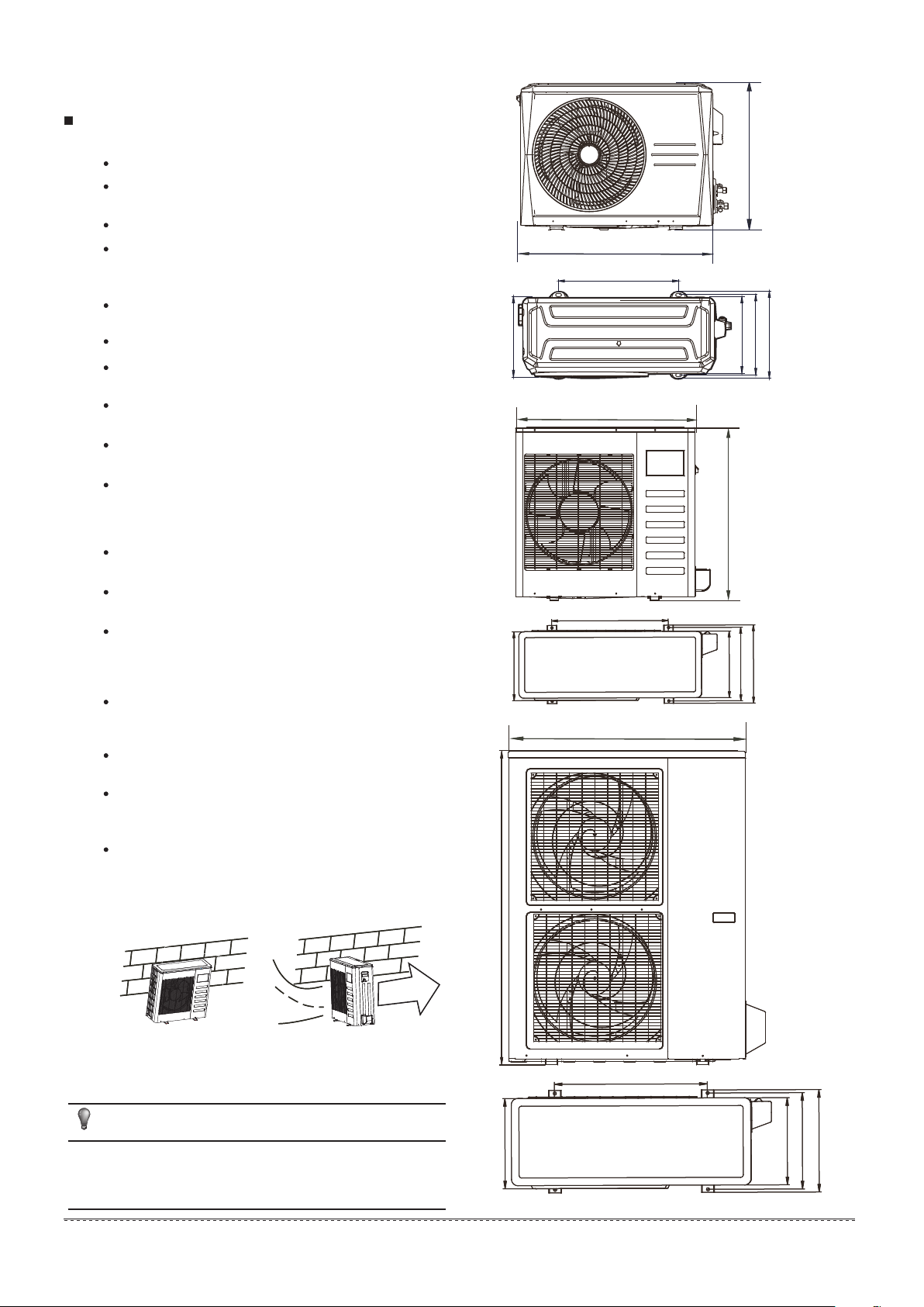
2.2 Figure of body size
A
B
A
B
F
F
A
H
H
H
EFC
D
Fig 2.2
H
D
D
C
C
E
E
Fig 2.3
X
O
O
X
NOTENOTE
All the figures in this manual are for explanation purpose only.
They may be slightly different from the air conditioner you
purchased.The actual uint shall prevail.
installation manual
installation manual
2
2
Fig 2.1
Fig 2.1
mmmm
mmmm
B
F
F
C
C
E
E
Fig 2.4
Fig 2.4
D
D
Page 5

Table 2-1 mm
1170
REMARK
Fig.2-2
Fig.2-2
Fig.2-3
Fig.2-4
MODEL A B C D E H
03
722 453 302 327 260 555300
05~07
14~16
795 514 340 365 287 550330
10
990 624 366 396 340 965345
590 378 400 330 350900
F
(in=mm/25.4)
2.3 Space of installation and maintenance
(Wall or obstacle)
Air inlet
>30cm
/11.81in
N
Air inlet
M
/78.74in
>200cm
Air outlet
>30cm
/11.81in
Maintain channel
>60cm
/23.62in
P
Fig 2.5
3 INSTALL THE CONNECTING PIPE
3.1 Preparation and Caution
Before installation make sure the height difference, the
length of refrigerant pipe, and the number of the bends
between the indoor unit and outdoor unit meet the
following requirements:
Table 3-1
The type of models
R410A Split type air conditioner
Model
03/05/07
10/14/16
The length of
refrigerant pipe
20m/65.8ft
30m/98.7ft
The outdoor unit is charged with rating refrigerant amount in
the factory. Additional charge refers to the table below:
Table 3-2
liquid tube(mm) R410A
Ø6.35
Ø9.53
NOTE:the table above refer to the liquid tube.
NOTE:The number of bends is up to the length of the max
height drop.Usually for each 10m/32.9ft need a bend.
0.022kg/m×(L-5)
0.060kg/m×(L-5)
unit:m
The max
height drop
10m/32.9ft
20m/65.8ft
2.4 Moving and installation
Since the gravity center of the unit is not at its physical
center, so please be careful when lifting it with a sling.
Never hold the inlet of the outdoor unit to prevent it from
deforming.
Do not touch the fan with hands or other objects.
Do not lean it more than 45, and do not lay it sidelong.
Make concrete foundation accoding to the sepecif-ications of
the outdoor units.(Refer to Fig.2-6)
Fasten the feet of this unit with bolts firmly to prevent it from
collapsing in case of earthquake or strong wind.(Refer to
Fig.2-6)
>60cm
/23.62in
Fix with bolt
CAUTION
All field piping must be provided by a licensed
refrigeration technician and must comply with the
relevant local and national codes.
Prevent let air, dust, or other impurities enter in the pipe
system during installation.
Insulation pipe shall be used to the gas piping and the
liquid piping. Otherwise, the condensate may happen.
3.2 The Procedure of Connecting Pipes
1)
Measure the required length of the connecting
pipe, then make it by the following way.
Connect the indoor unit first, then the outdoor unit.
Bend the tubing in proper way. Do not twist the pipe.
Bend the pipe with thumb
min-radius 100mm/3.94in
Fig 3.1
Fig 2.6
Put some refrigerant oil on the surfaces of the flare pipe
and the joint nuts then wrench it for 3~4 rounds with
hands before fasten the flare nuts.
Use frozen oil
Fig 3.2
installation manual
3
Page 6

Be sure to use two wrenches simultaneously when you
connect or disconnect the pipes.
Make the ends straight
Table 4-1
Model
Size of joint pipes for 410A outdoor unit
the size of main pipe(mm)
Gas side Liquid side
Fig 3.3
The service valves of the outdoor unit should be completely
closed(as original status).Every time to connect,first to loosen
nuts, then connect the flare pipes within 5 minutes. If the nuts
have been loosened for a long time, dusts and other impurities
may enter the pipe system and may cause malfunction.So
please expel the air out of the pipe with refrigerant before
connection.
Expel the air after connecting the refrigerant pipe with the
indoor unit and the outdoor unit.
Then fasten the nuts at the service valves.
Bend the connecting pipe of small wall thickness.
Cut out a proper concave at the bending part of the
insulating pipe.
Then expose the pipe(cover it with tapes after bending).
To prevent twist of deforming, please bend the pipe at a
proper radius.
NOTE
The bending angle should not exceed 90 .
Bending position is preferably in the middle of the bendable pipe.
Do not bend the pipe more than three times.
Be sure to use the same insulating materials when you buy the
brass pipe. (More than 9mm/0.35in thick)
03/05
07
10
14/16
Drop height between indoor
unit and outdoor unit
Φ12.7/0.501in
Φ12.7/0.501in
Φ19/0.748in
Φ19/0.748in Φ9.52/0.375in
Outdoor unit
Max.pipe length L≤20m(03/05/07)
Max.pipe length L≤30m(10/14/16)
H≤10m/32.9ft (03/05/07)
H≤20m/65.8ft(10/14/16)
Φ6.35/0.25in
Φ9.52/0.375in
Φ9.52/0.375in
2) Place The Pipe
Drill a hole in the wall (suitable just for the size of the wall
sleeve), then set on the fittings such as the wall sleeve and its
cover.
Bind the connecting pipe and the cables together tightly with
binding tapes.
Pass the bound connecting pipe through the wall sleeve from
outside. Make sure of the pipe allocation not to damage the
copper tubes.
3)
Connect the pipes.
Expel the air with a vacuum pump or refrigerant.
4)
Open the service valves of the outdoor unit .
5)
Check the refrigerant leakage. Check all the joints
6)
with the leak detector or soap water.
Cover the joints of the connecting pipe with the
7)
insulation foam, and bind them well with the tapes to
prevent potential leakage.
4 REFRIGERANT PIPE
Indoor unit
5 REFRIGERANT PIPE CONNECTION
5.1 Expel The Air
Flaring
1)
Cut a pipe with a pipe cutter. (Refer to Fig.5-1)
90
Insert a flare nut into a pipe and flare the pipe.
2)
Fasten the nut
Put the connecting pipes at the proper position,
wrench the nuts with hands then fasten it with
two wrenches simultaneously. (Refer to Fig 5.2)
Lean crude burr
Fig 5.1
Fig 4.1
4.1 Size of joint pipes for outdoor unit
Base on the following tables, select the diameters of
the outdoor unit connective pipes. In case of the
main accessory pipe large than the main pipe, take
the large one for the selection.
installation manual
4
Fig 5.2
Page 7

CAUTION
Too large torque will harm the bellmouthing and too small will
cause leakage. Please determine the torque according to
Table 5-1.
Table 5-1
Pipe gauge
Ø6.35/0.25in 8.3/0.327in 8.7/0.343in
Ø9.52/0.375in 12.0/0.472in 12.4/0.488in
Ø12.7/0.5in 15.4/0.606in 15.8/0.622in
Ø15.9/0.626in
Ø19.1/0.725in
Tightening torque
14.2~17.2 N.m
(144~176 kgf.cm)
32.7~39.9 N.m
(333~407 kgf.cm)
49.5~60.3 N.m
(504~616 kgf.cm)
61.8~75.4 N.m
(630~770 kgf.cm)
97.2~118.6 N.m
(990~1210 kgf.cm)
Flare dimensin A
min max
(mm)
18.6/0.732in 19.0/0.748in
22.9/0.902in 23.3/0.917in
Flare shape
°
4
±
90
45
°
±
2
A
R0.4~0.8
Flare nut
Stopper
Cap
Valve body
Valve stern
Fig 5.4
CAUTION
Both service valves should be open before test operation.
Each air conditioner has two service valves of different
sizes.(Refer to Fig 5.4)
Expel the air with a vacuum pump
3)
(Please refer to its manual for the way of using manifold
valve)
Loosen and remove the nuts of service valves A and B,
and connect the charge hose of the manifold valve with
the maintenance terminator of service valve A. (Be sure
that service valves A and B are both closed)
Connect the joint of the charge hose with the vacuum
pump.
Open the Lo-lever of the manifold valve completely.
Turn on the vacuum pump. At the beginning of pumping,
loosen the nut of service valve B a little to check whether
the air comes in (the sound of the pump changes, and
the indicator of compound meter turns below zero). Then
fasten the nut.
When the pumping has finished, close the Lo-lever of the
manifold valve completely and turn off the vacuum pump.
When you have pumped for over 15 minutes, please
confirm that the indicator of multimeter is on -1.0X10⁻⁵Pa
(-76cmHg)
Loosen and remove the nuts of service valves A and B to
open service valve A andB completely, then fasten nuts.
Disassemble the charge hose of service valve A, and
fasten the nut.
Manifold valve
Multi-meter
Pressure meter
5.2 Check the Leakage
Check all the joints with the leak detector or soap water.
(Refer Fig 5.5 as a reference illustration)
in the chart
A......Lo-stop valve
B......Hi-stop valve
C,D..Joints of the connecting pipe to the indoor unit.
D
Check-point of indoor unit
Check-point of outdoor unit
C
B A
Fig 5.5
5.3 Insulation
Be sure to completely insulate all the exposed parts of the flare
pipes.
Incomplete insulation may cause condensate.
6. HEAT INSULATION OF THE PIPE
6.1 Heat Insulation Of The Pipe
In order to prevent faults caused by condensate of the
refrigerant pipe and drain pipe, perform condensate prevention
and heat insulation properly.
-76 cmHg
Lo-lever
Charge hose
Lo-lever
Hi-lever
Charge hose
Vac uum pump
Fig 5.3
CAUTION
If it is forecast that high humidity/temperature environment
(condensate temperature is over 23℃) may exist in the ceiling,
e.g., inside the ceiling with slab, ceiling which is in the same
environment as the outdoor air), it is necessary to apply 10mm
or thicker adiabatic wool (16~20kg/m2 ) to the refrigerant pipe
and the drain pipe in addition to applying the general heat
insulation materials. Enough heat insulation materials should
also be applied to the refrigerant joint and the pipe joint.
installation manual
5
Page 8

6.2 Heat Insulation Of The Refrigerant Pipe
Please use heat-resistant materials as heat insulation materials
of the air-side pipe. (e.g., EPT)
Cover heat insulation materials separately at the liquid side and
the air side. Moreover, perform heat insulation thoroughly for the
air-side pipes of the indoor unit, and prevent water from dripping
outside the unit.
(air-side pipe)
Indoor unit
Fig.6-1
After applying the auxiliary heat insulation materials, use
vinylresin tape to seal it lest water leak.
7 CONNECTIVE DIAGRAM
Gas side
Liquid side
8 WIRING
The appliance shall be installed in accordance with
national wiring regulations.
The air conditioner should use separate power supply
with rated voltage.
The external power supply to the air conditioner should
be grounded, which is linked to the ground wiring of the
indoor and outdoor unit.
The wiring work should be done by qualified persons
according to wiring diagram.
A circuit breaker and a residual current device (RCD) with
above 10mA rating shall be installed in the power circuit
according to the national rule.
Be sure to locate the power wiring and the signal wring
well to avoid cross-disturbance.
Do not turn on the power until you have confirmed
proper wiring.
The power cord type is H07RN-F.
NOTE
Refer to EMC Directive 2004/108/EC
To prevent flicker impressions during the start of the
compressor,following installation conditions do apply.
The power connection for the air conditioner has to be
1
done at the main power distribution. The distribution has
to be of a low impedance, normally the required
impedance reaches at a 32A fusing point.
No other equipment has to be connected with this power
2
line.
For detailed installation acceptance please refer to your
3
power supplier, if restrictions do apply for products like
washing machines, air conditioners or electrical ovens.
4
For power details of the air conditioner refer to the rating
nameplate of the product.
For any question contact your local dealer.
5
Fig 7.1
NOTE
For ensuring throttled efficiency , Please mount the Orifice as
horizontally as possible; and anti-shock rubber should be
wrapped at external of the Orifice for denoise.
8.1
Connect the cable
Disassemble the cover.(If there isn't a cover on the outdoor
unit, disassemble the screw from the maintenance board, and
pull it in the direction of the arrow to remove the protection
board.) (Refer to Fig 8.1)
Connect the cables to the terminals correspondingly.
Re-install the cover or the protection board.
Wiring figure
8.2
Cover
Fig 8.1Protection board
NOTE
All the figures in this manual are for explanation purpose only.
They may be slightly different from the air conditioner you
purchased(depend on model).The actual unit shall prevail.
installation manual
6
Page 9

9 ELECTRIC CONNECTION
Power supply
Power supply
CAUTION
Use special power supply for the air conditioner. Design power
supplies specific to the indoor unit and outdoor unit. The supply
voltage must comply with the nominal voltage.
The external supply circuit of the air conditioner must have a
ground wire, and the power supply ground wire of the indoor unit
must be connected with the external ground wire firmly.
The wiring must be performed by professional technicians
according to the circuit diagram labels.
Distribute the wires according to the relevant electric technical
standards promulgated by the State, and set the Residual
Current-operated Circuit Breaker (RCCB) properly.
The power wire and the signal wire shall be laid out neatly and
properly, without mutual interference or contacting the
connection pipe or valve.
No power cable is attached to this equipment. The user can
select the power cable by reference to the stipulated power
supply specifications. No joint of wires is allowed.
Upon completion of wire connection, double check it and then
connect the power supply.
An all-pole disconnection device which has at least 3mm
separation distance in all pole and a residual current
device(RCD)with the rating of above 10mA shall be incorporated
in the fixed wiring according to the national rule.
The appliance shall be installed in accordance with national
wiring regulations.
Specifications of power supply
Model Power
of the main power
suppliy/fuse(A)
MCCU-03CN1A 20/16
Switch capacity
MCCU-05CN1A 30/20
220-240V~
50Hz
MCCU-07CN1A 40/30
MCCU-10CN1 25/20
MCCU-14CN1 25/20
380-415V
3N~ 50Hz
MCCU-16CN1 45/35
Outdoor unit power
cable includes
grounded wire
RVV-300/500
2X2.5+1X1.5 mm
RVV-300/500
2X4.0+1X2.5 mm
RVV-300/500
2X6.0+1X4.0 mm
RVV-300/500
4X4.0+1X2.5 mm
RVV-300/500
4X4.0+1X2.5 mm
RVV-300/500
4X10.0+1X6.0 mm
Connective
wire of indoor
outside unit
2
2
2
2
RVV-300/500
1X1.0 mm
2
2
Switch/ Fuse
(Available locally)
Power wiring
(indoor)
Power linking wirng(Outdaoor)
Indoor
unit
Outdoor unit
Ground wiring
Ground wiring
Weak elec-signal link wiring
Ground the air conditioner properly in case to affect its
anti-interference function
Fig 9.2
NOTE
Please identify outdoor main unit and auxilary unit. Only main unit
connects with signal wire of indoor unit. Users should adjust the
dial on electric control board of outdoor unit as follows, otherwise
incorrect adjustment may cause malfunction.
10 ELECTRIC WIRE DIAGRAM
Y/G
4
3
(N)
1 2
Y/G
-
SNL
-
2
A B C N 1
Y/G
Power supply:
-2
40V~ 50Hz
220
3-cord cable
RVV-300/500 2X2.5+1x1.5 mm
RVV-300/500 2X4.0+1x2.5 mm
T O INDOOR UNIT
Power supply:
-2
40V~ 50Hz
220
3-cord cable
RVV-300/500 2X6.0+1x4.0 mm
* S: RVV-300/500 1X1.0 mm
T O INDOOR UNIT
Power supply:
-
415V 3N~ 50Hz
380
3-cord cable
RVV-300/500 4X4.0+1x2.5 mm
RVV-300/500 4X4.0+1x2.5 mm
T O INDOOR UNIT
RVV-300/500 4X10.0+1x6.0 mm
* 1: RVV-300/500 1X1.0 mm
2
(MCCU-03CN1A)
2
(MCCU-05CN1A)
2
(MCCU-07CN1A)
2
2
(MCCU-10CN1)
2
(MCCU-14CN1)
2
(MCCU-16CN1)
2
Power wires
The power wires are as follows: (schematic diagram)
RCCB
Outdoor unit
Manual switch
Outdoor unit power supply
Fig 9.1
Fig 10.1
NOTE
Pay attention to the phase sequence of the power supply. If the
phase sequence is reversed, the compressor will not start.
Meanwhile, the fault indicator of the outdoor electric control
board will light up. For details, see Outdoor unit wring diagram
on the cover plate of the electric control box .
After shifting the phase sequence, power on the unit until the
fault indicator goes out and the compressor starts up normally.
installation manual
installation manual
7
Page 10

11 TRIAL RUN
Please conduct in accordance with “Trial Run Tenor Nameplate”
on the electric control box.
CAUTION
Perform the trial run only after the outdoor unit has been
powered on for over 12 hours.
Check that all valves are opened before trial run.
Check the electric safety before trial run.
Do not perform compulsory operation in any way.(It is very
dangerous if the protection device is not active)
Perform trial run only after all installations are finished.
Confirm the following issues before trial operation, and the
box for the confirmed items.
Check whether the indoor unit and the outdoor are
installed properly.
Check whether the piping and wiring are correct.
Check whether the refrigerant pipeline system is
inspected for leakage.
Air flow of the indoor unit
Table 11-2
Model
MCCU-03CN1A
MCCU-05CN1A
MCCU-07CN1A
Air flow of the indoor unit
500~650m3/h
700~900m3/h
1000~1250m
3
/h
Check whether the drain is smooth.
Check whether the heat insulation is perfect.
Check whether the ground cables are connected
correctly.
Check whether the pipe length and the refrigerant
amount are recorded.
Check whether the supply voltage is equal to the rated
voltage of the air conditioner.
Check whether any obstacles exist at the air
inlet/outlet of the indoor or outdoor unit.
Open the gas valve and the liquid valve.
Connect the power supply to preheat the air
conditioner.
Safety precautions
The electric circult must be installed RCCB and manual switch
Table 11-1
Cooling
operation
Dewetting
operation
Outdoor temperature:17~46°C
Intdoor temperature:≥17°C
Outdoor temperature:17~46°C
Intdoor temperature:17~32°C
installation manual
8
Page 11

Page 12

16123000A18669 V1.0
Page 13

本页不打印
规格:A4
材质:100g双胶纸
更改记录
 Loading...