

Page 1

MCAC-UTSM-2008-11 Contents
Contents i
Part 1 General Information ..................................................................................................... 1
Part 2 Indoor Units .................................................................................................................. 7
Part 3 Outdoor Units ............................................................................................................. 88
Part 4 Installation ................................................................................................................ 127
Part 5 Control ...................................................................................................................... 136
※The specifications, designs, and information in this book are subject to change without notice for
product improvement.
Page 2

Page 3

MCAC-UTSM-2008-11 General Information
General Information 1
Part 1
General Information
1. Model Names of Indoor/Outdoor Units ...................... 2
2. External Appearance .................................................. 3
2.1 Indoor Units ................................................................................. 3
2.2 Outdoor Units............................................................................... 4
3. Nomenclature ............................................................. 5
4. Features ...................................................................... 6
Page 4
Model Names of Indoor/Outdoor Units MCAC-UTSM-2008-11
2 General Information
1. Model Names of Indoor/Outdoor Units
Outdoor unit model Power supply (V-ph-Hz) Compressor type Compressor brand Matched indoor units model
MOU-12HN1 220~240-1-50 ROTARY MIDEA-TOSHIBA
MCA-12HRN1
MUB-12HRN1
MOUA-18HN1 220~240-1-50 ROTARY MIDEA-TOSHIBA
MCA-18HRN1
MUB-18HRN1
MOUA-24HN1 220~240-1-50 ROTARY MIDEA-TOSHIBA
MCC-24HRN1
MUB-24HRN1
MOU-30HN1 220~240-1-50 SCROLL SANYO
MCC-30HRN1
MUB-30HRN1
MOU-30HN1-R 380~415-3-50 SCROLL SANYO
MCC-30HRN1-R
MUB-30HRN1
MOU-36HN1 220~240-1-50 SCROLL SANYO
MCC-36HRN1
MUB-36HRN1
MOU-36HN1-R 380~415-3-50 SCROLL SANYO
MCC-36HRN1-R
MUB-36HRN1
MOUA-48HN1-R 380~415-3-50 SCROLL DAIKIN
MCC-48HRN1-R
MUB-48HRN1-R
MOUA-60HN1-R 380~415-3-50 SCROLL SANYO MUB-60HRN1-R
Page 5
MCAC-UTSM-2008-11 External Appearance
General Information 3
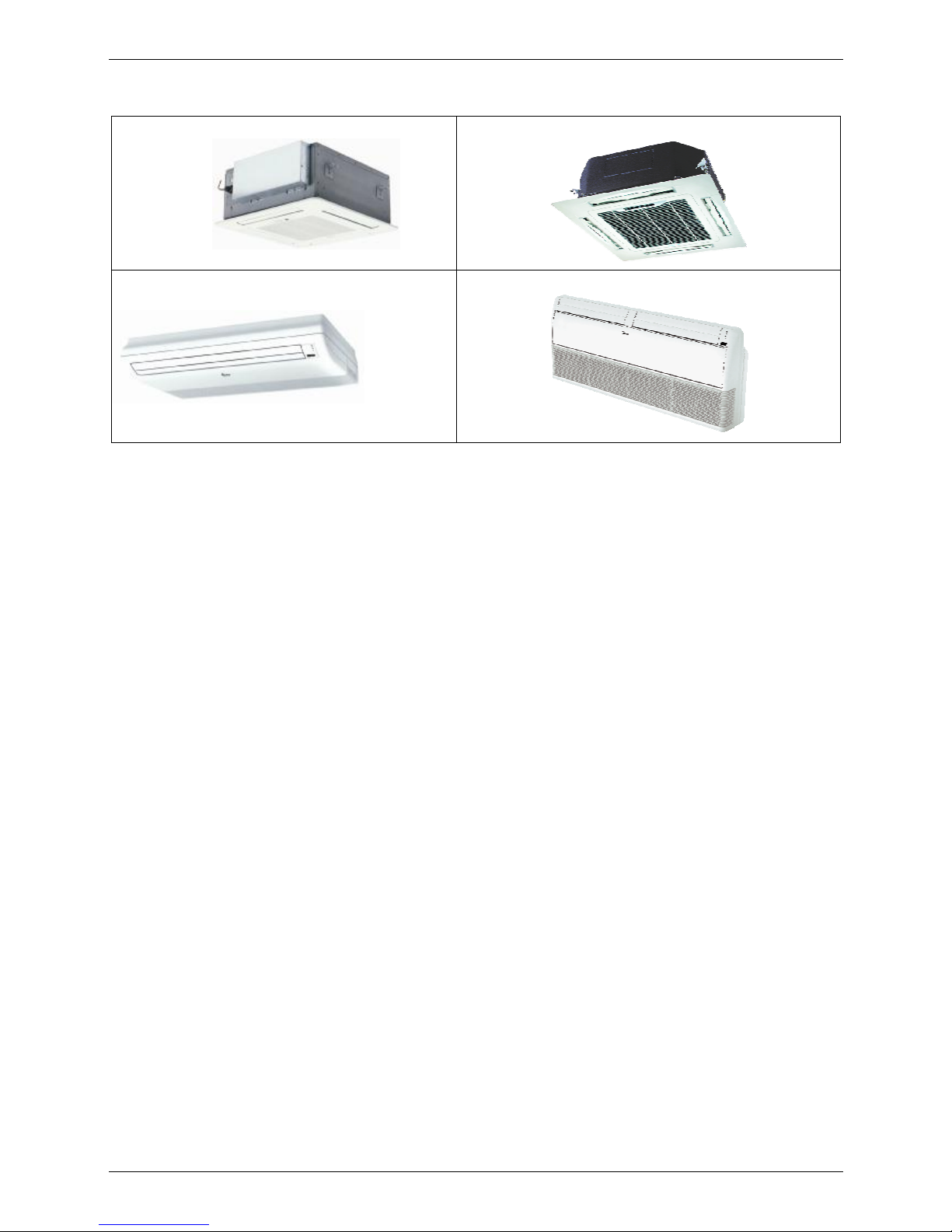
2. External Appearance
2.1 Indoor Units
Four-way cassette type (compact)
Four-way cassette type
Ceiling & floor type
Ceiling & floor type
Page 6
External Appearance MCAC-UTSM-2008-11
4 General Information
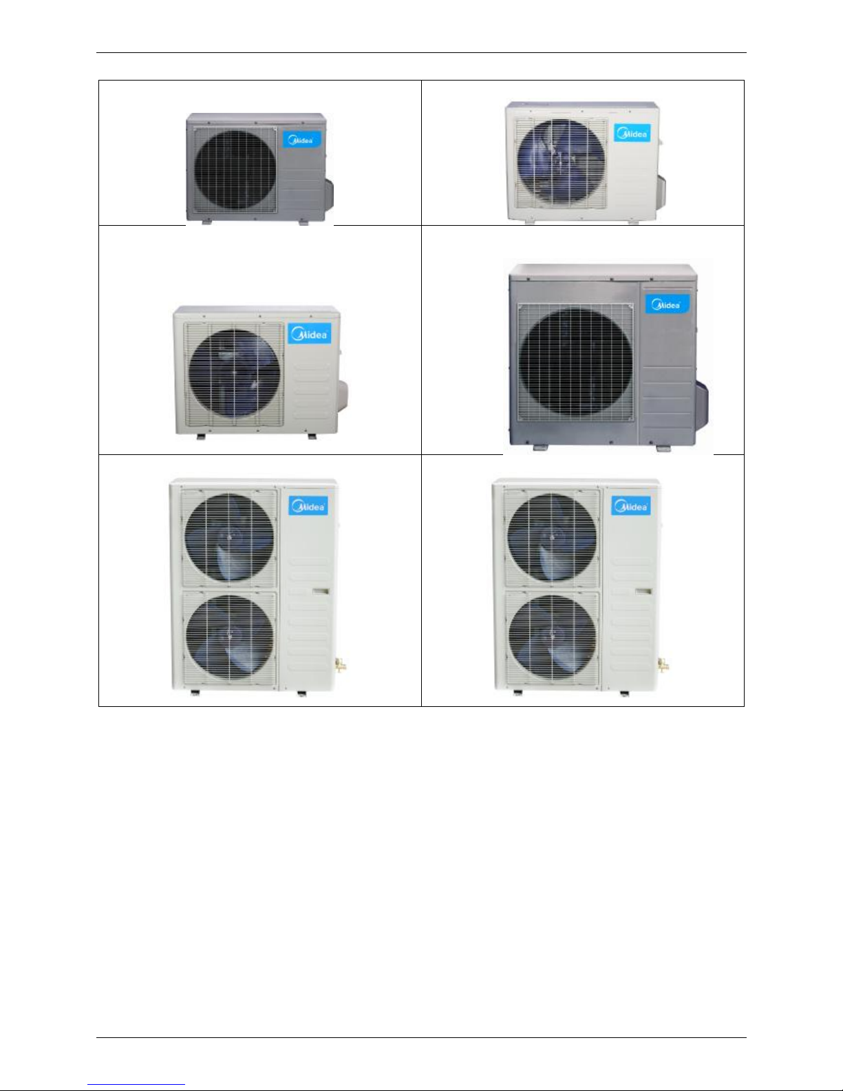
2.2 Outdoor Units
12,000Btu/h
18,000Btu/h
24,000Btu/h
30,000~36,000Btu/h
48,000Btu/h
60,000Btu/h
Page 7
MCAC-UTSM-2008-11 Nomenclature
General Information 5
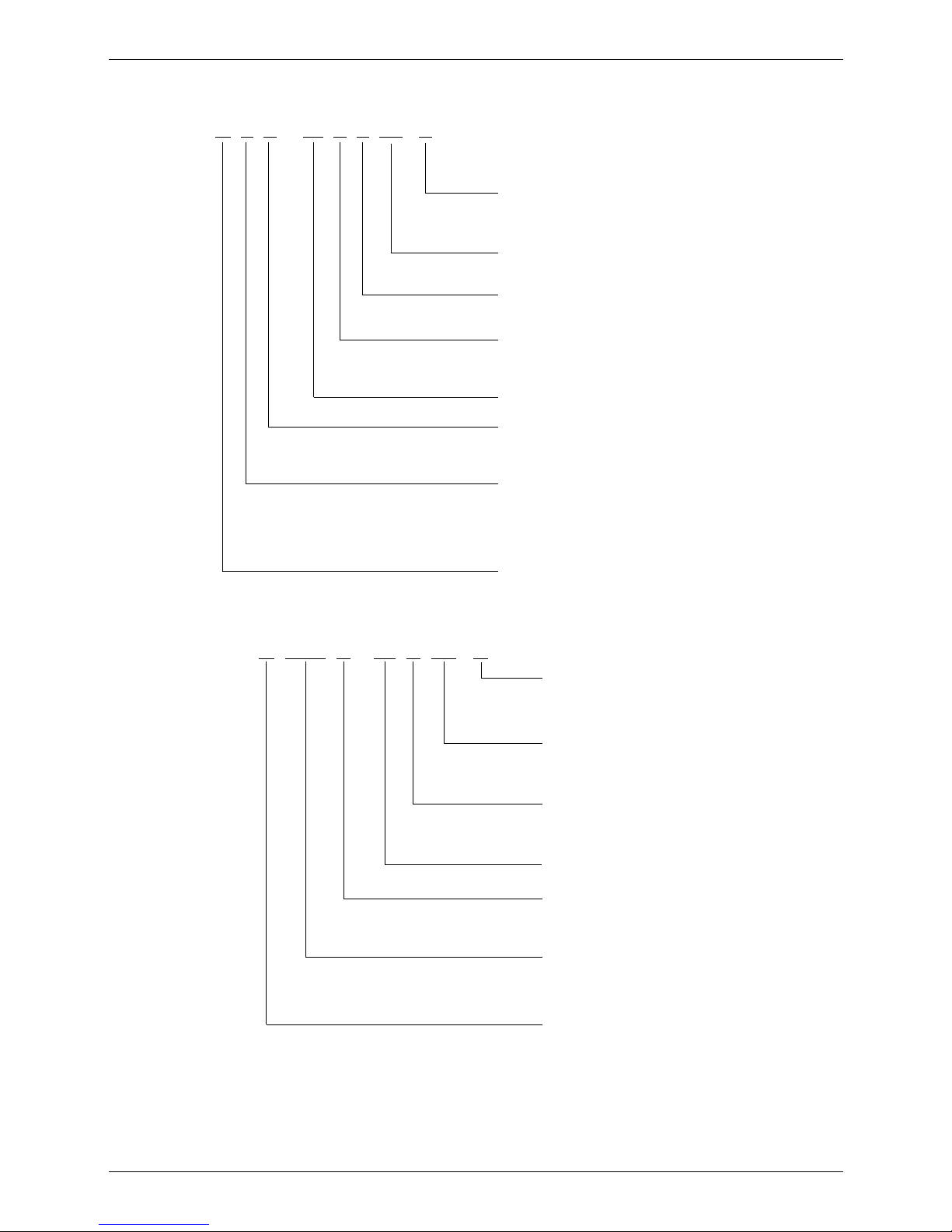
3. Nomenclature
3.1 Indoor Unit
M C C - 48 H R N1 - R
Power Supply
R 380~415V, 3N, 50Hz
-- 220~240V, 1N, 50Hz
Refrigerant Type
N1 R410A
Control Mode
W Wired Control R Remote Control
Function Code
C Cooling Only
H Cooling & Heating
Capacity (×1000Btu/h)
Product Series
A Time A Designed B Time B Designed
C Time C Designed
Indoor Unit Type
T Duct
H High Static Pressure Duct
C Cassette
U Ceiling & Floor
Midea
3.2 Outdoor Unit
Power Supply
R 380V~415V, 3N, 50Hz
-- 220~240V, 1N, 50Hz
Refrigerant Type
N1 R410A
Function Code
C Cooling Only
H Cooling & Heating
Capacity (×1000Btu/h)
Product Series
A Time A Designed
B Time B Designed
Universal Outdoor Unit
O Outdoor unit
U Universal
Midea
M O U A - 48 H N1 - R
Page 8
Features MCAC-UTSM-2008-11
6 General Information
4. Features
1. High quality coils: The coil is constructed of advanced inner grooved copper tube and aluminum fins.
2. Anti-rust, 500 hours salt spray test.
3. Low operation sound level: Well-known stable and quiet running fan motor.
4. Well-known compressor.
5. Compact design: Smaller dimension and larger stuffing capacity.
6. Universal outdoor unit design.
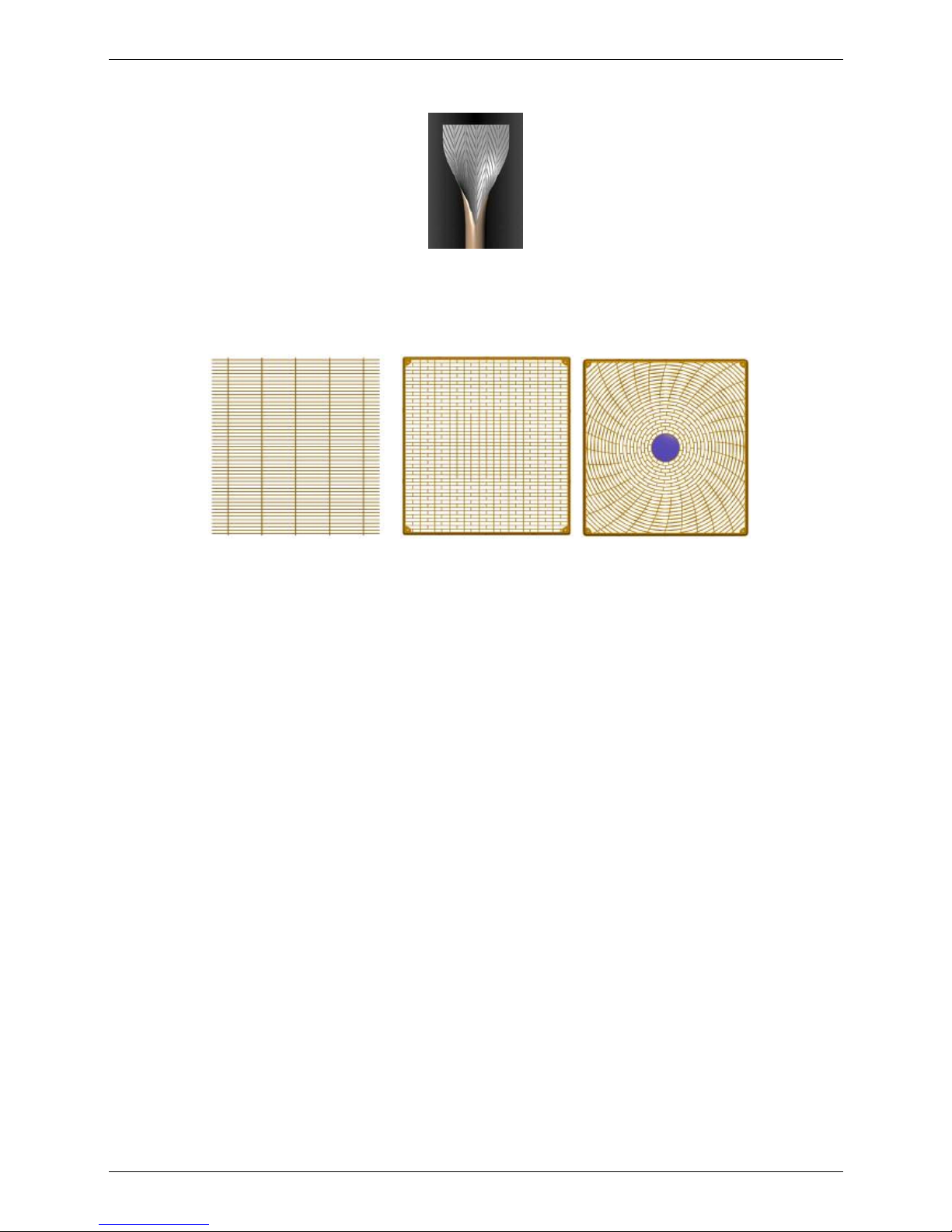
7. Optional air outlet grille: plastic type and wire type.
Metal grille Plastic type Plastic type
8. Optional low temperature cooling module.
9. R410A environment friendly refrigerant.
Page 9

MCAC-UTSM-2008-11 Indoor Units
Indoor Units 7
Part 2
Indoor Units
Four-way Cassette Type (Compact) .............................. 8
Four-way Cassette Type............................................... 21
Ceiling & Floor Type ..................................................... 53
Page 10

Four-way Cassette Type (Compact) MCAC-UTSM-2008-11
8 Indoor Units
Four-way Cassette Type (Compact)
1. Features ...................................................................................................... 9
2. Specifications .......................................................................................... 10
3. Dimensions .............................................................................................. 11
4. Service Space .......................................................................................... 11
5. Wiring Diagram ........................................................................................ 12
6. Air Velocity and Temperature Distributions .......................................... 13
7. Capacity Tables ........................................................................................ 14
8. Electric Characteristics ........................................................................... 16
9. Sound Levels ........................................................................................... 16
10. Exploded View ....................................................................................... 17
11. Accessories ............................................................................................ 18
12. The Specification of Power ................................................................... 18
13. Field Wiring ............................................................................................ 19
Page 11
MCAC-UTSM-2008-11 Features
Indoor Units 9
1. Features
(1) Low operation noise
---Streamline plate ensures quietness
---Creates natural and comfortable environment
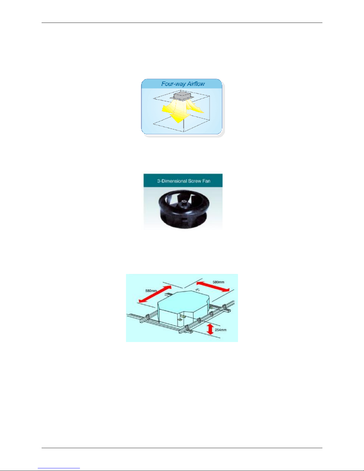
(2) Efficient cooling
---Equal, fast and wide—range cooling
(3) The adoption of the most advanced 3-Dimensional Screw Fan
---Reduces the air resistance passing through
---Smoothes the air flow
---Makes air speed distribution to the heat exchange uniform
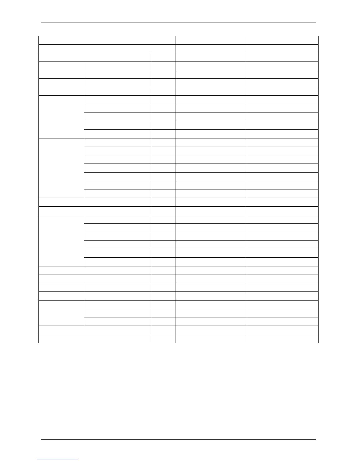
(4) Improvement for easy installation and maintenance
---Little space is required for installation into a shallow ceiling
---Because of the compactness and weight reduction of the main unit and panel, all models can be
installed without a hoist
Page 12
Specifications MCAC-UTSM-2008-11
10 Indoor Units
2. Specifications
Model MCA-12HRN1 MCA-18HRN1
Code 220042002960 220042001870
Power supply V-ph-Hz
220~240-1-50 220~240-1-50
Cooling
Capacity kW 3.2 5.3
Input W 1100 1900
Heating
Capacity kW 4 6
Input W 1050 1900
Indoor fan motor
Model YDK45-4F YDK45-4F
Brand Welling Welling
Input W 56.7/51.5/44.4 56.7/51.5/44.4
Capacitor uF 1.5uF/450V 2.5uF/450V
Speed(Hi/Mi/Lo) r/min 930/845/680 930/845/680
Indoor coil
Number of rows 2 2
Tube pitch(a)×row pitch(b) mm 21×13.37 21×13.37
Fin spacing mm 1.4 1.4
Fin type (code) Hydrophilic aluminium Hydrophilic aluminium
Tube outside dia.and type mm φ7 Inner grooved copper tube φ7 Inner grooved copper tube
Coil length × height × width
mm 1215×210×26.74 1215×210×26.74
Number of circuits 5 5
Indoor air flow (Hi/Mi/Lo) m3/h 680/600/400 860/760/500
Indoor noise level (sound pressure) dB(A) 41/38/35 42.5/39.4/35.8
Indoor unit
Dimension (W×H×D)(body) mm 580×254×580 580×254×580
Packing (W×H×D)(body) mm 750×340×745 750×340×745
Dimension (W×H×D)(panel) mm 650×30×650 650×30×650
Packing (W×H×D)(panel) mm 715×115×715 715×115×715
Net/Gross weight(body) kg 21/28 21/27
Net/Gross weight(panel) kg 3/5 3/5
Refrigerant type R410A R410A
Design pressure MPa 4.4/2.6 4.4/2.6
Refrigerant piping Liquid side/ Gas side mm φ6.4/φ12.7 φ6.4/φ12.7
Drainage water pipe diameter mm ODφ25 ODφ25
Connection wiring
Power wiring mm2 3×2.5 3×2.5
Strong electric signal wiring mm2 5×2.5 5×2.5
Weak electric signal wiring mm2 1-core shield wire 1×0.5 1-core shield wire 1×0.5
Controller R11HG/E(standard) R11HG/E(standard)
Operation temperature ℃ 17-30 17-30
Notes: 1. Nominal cooling capacities are based on the following conditions:
Indoor temp: 27°CDB, 19°CWB; Outdoor temp: 35°CDB;
2. Nominal heating capacities are based on the following conditions:
Indoor temp: 20°CDB; Outdoor temp: 7°CDB, 6°CWB;
3. Actual noise level may differ, depending on the room structure, etc, since these noise values are from an anechoic
room.
Page 13
MCAC-UTSM-2008-11 Dimensions
Indoor Units 11
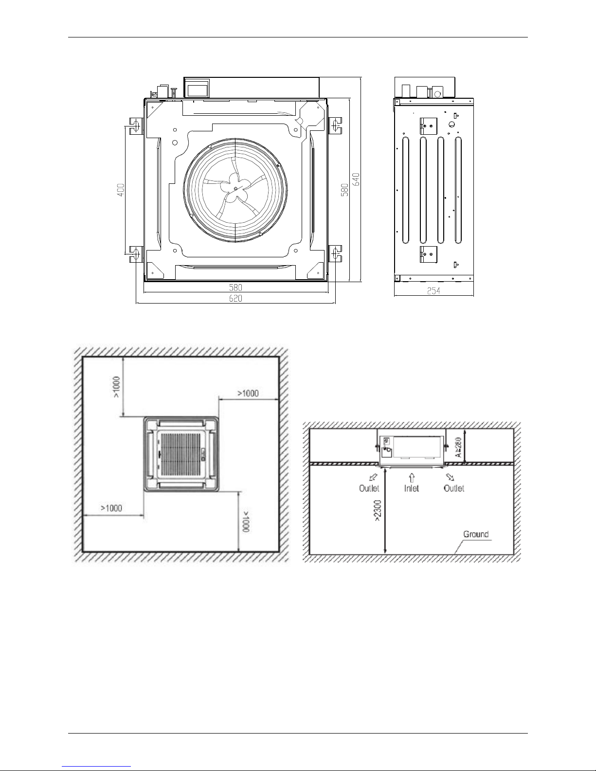
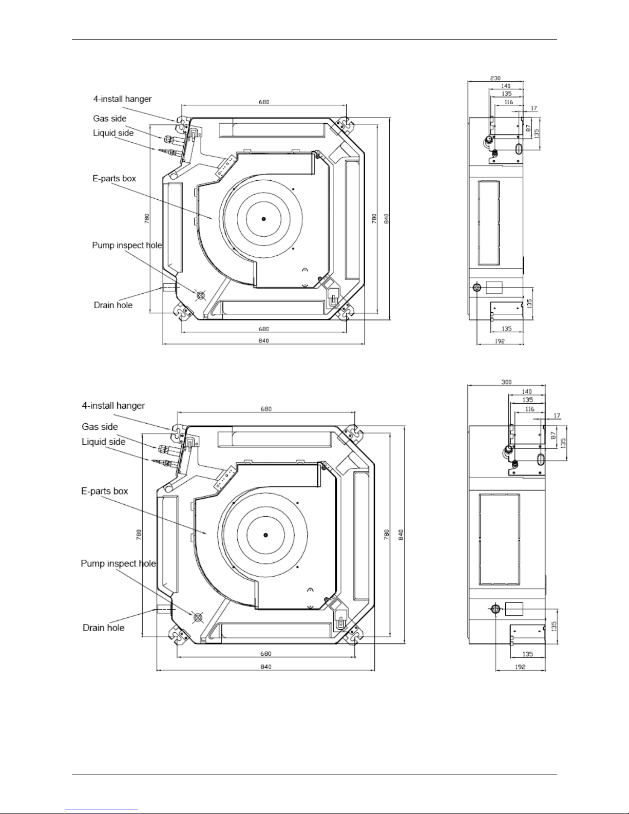
3. Dimensions
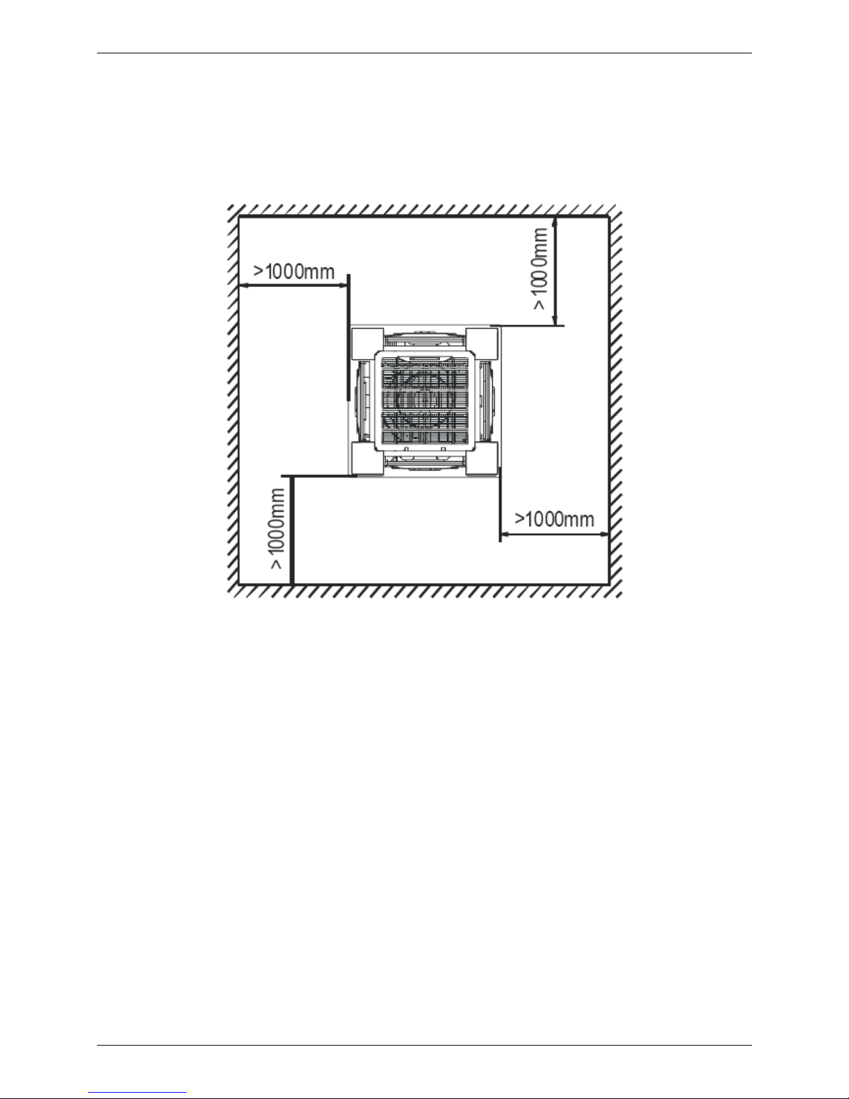
4. Service Space
Page 14
Wiring Diagram MCAC-UTSM-2008-11
12 Indoor Units
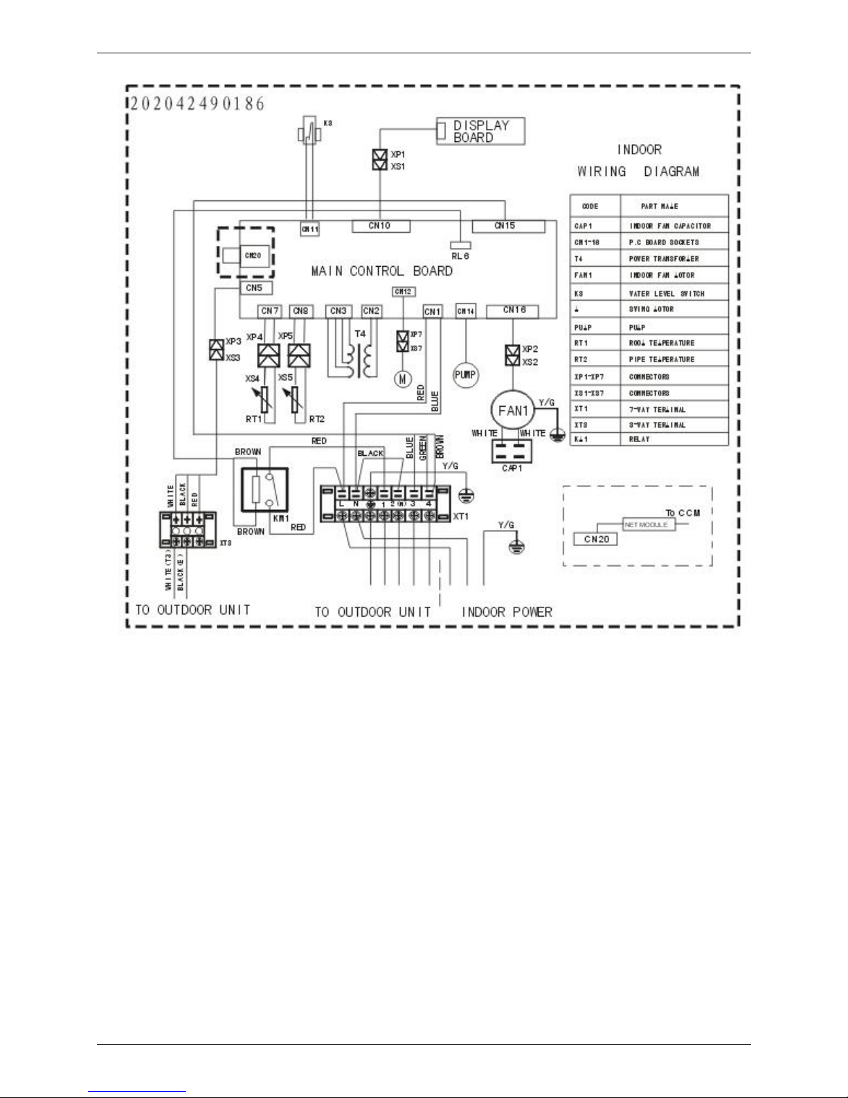
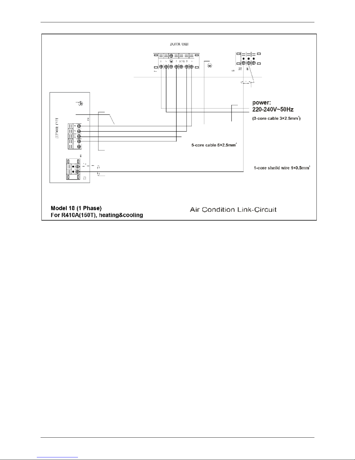
5. Wiring Diagram
Page 15
MCAC-UTSM-2008-11 Air Velocity and Temperature Distributions
Indoor Units 13
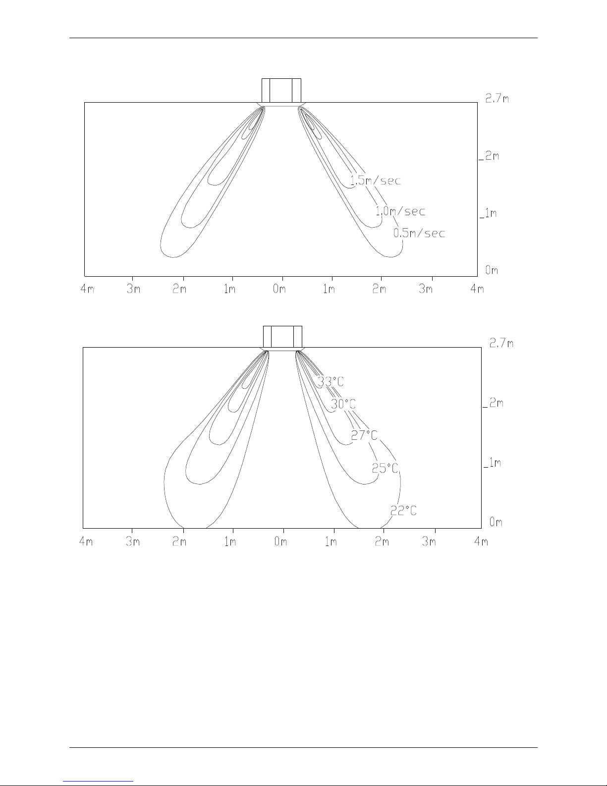
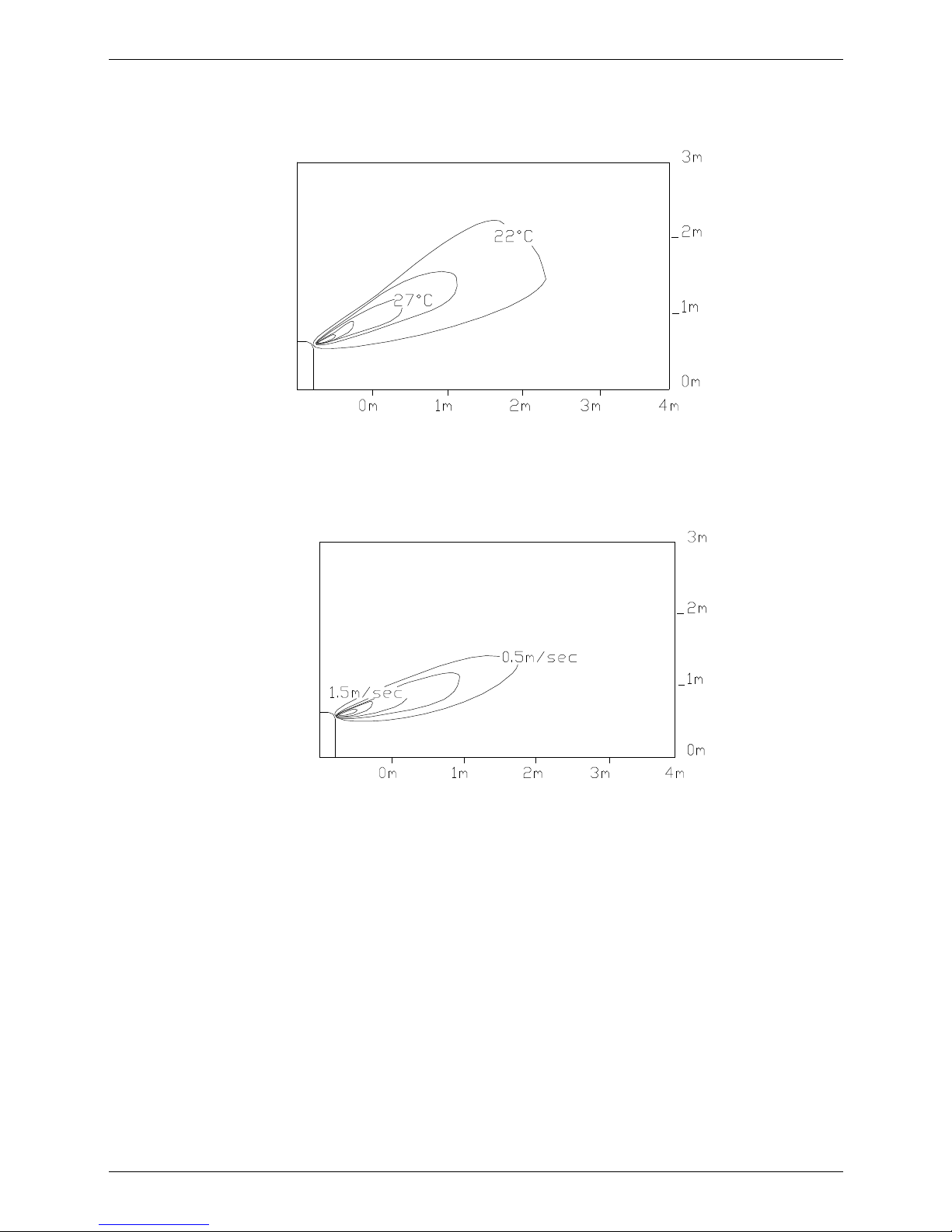
6. Air Velocity and Temperature Distributions
Airflow velocity
Temperature
Page 16
Capacity Tables MCAC-UTSM-2008-11
14 Indoor Units
7. Capacity Tables
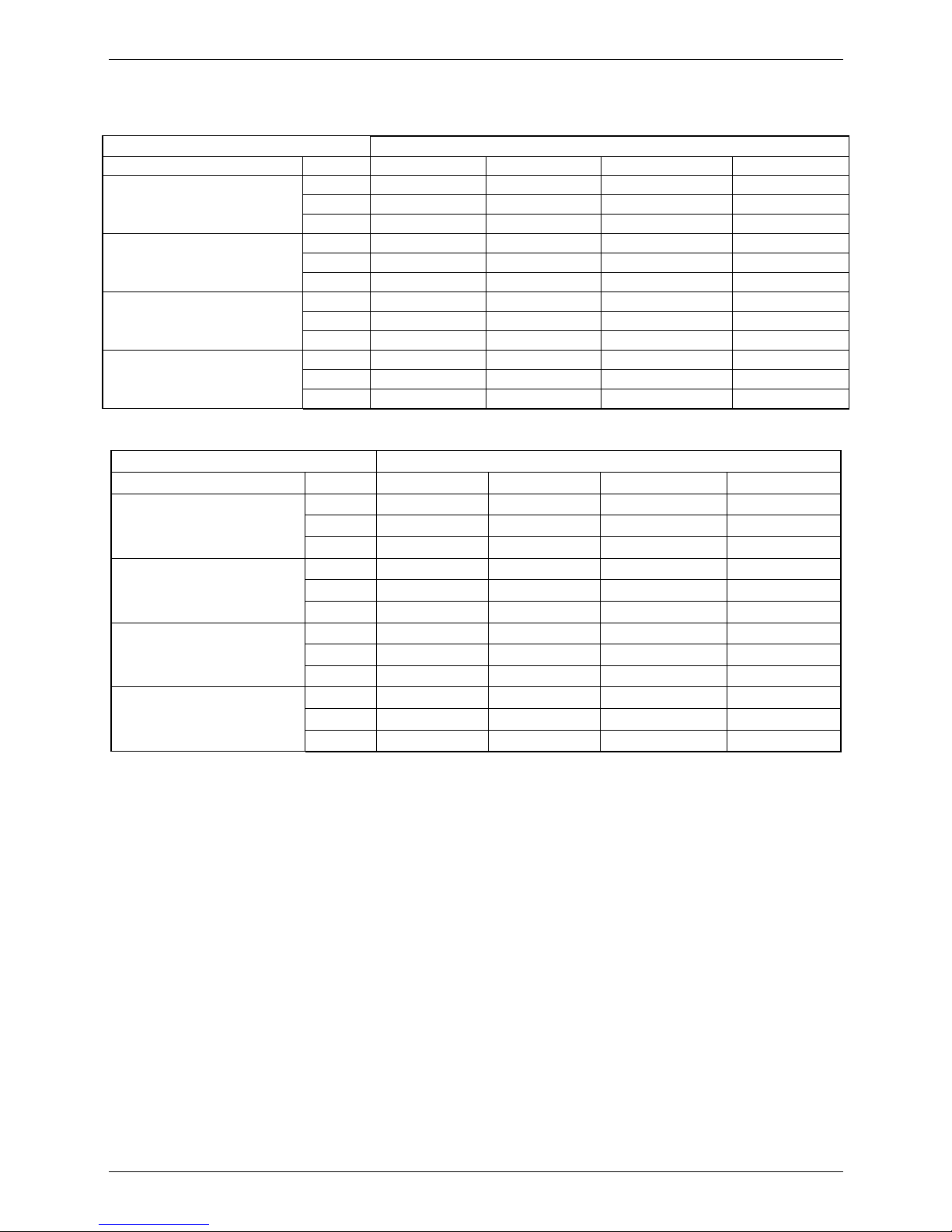
7.1 Cooling Capacity
MCA-12HRN1
Cooling Outdoor conditions (DB)
Indoor Conditions (kW) 21ºC 28ºC 35ºC 43ºC
21/15ºC DB/WB
TC 3.30 3.14 2.98 2.85
SC 2.44 2.41 2.38 2.39
Input 0.91 0.99 1.03 1.07
24/17ºC DB/WB
TC 3.39 3.23 3.07 2.88
SC 2.54 2.52 2.49 2.42
Input 0.97 1.03 1.08 1.13
27/19ºC DB/WB
TC 3.46 3.30 3.20 2.98
SC 2.56 2.54 2.50 2.44
Input 0.99 1.05 1.10 1.16
32/23ºC DB/WB
TC 3.52 3.39 3.33 3.07
SC 2.99 2.95 2.93 2.86
Input 1.03 1.08 1.16 1.20
MCA-18HRN1
Cooling Outdoor conditions (DB)
Indoor Conditions (kW) 21ºC 28ºC 35ºC 43ºC
21/15ºC DB/WB
TC 5.46 5.19 4.93 4.72
SC 4.04 4.00 3.94 3.96
Input 1.58 1.71 1.79 1.84
24/17ºC DB/WB
TC 5.62 5.35 5.09 4.77
SC 4.21 4.18 4.12 4.01
Input 1.67 1.79 1.86 1.96
27/19ºC DB/WB
TC 5.72 5.46 5.30 4.93
SC 4.24 4.20 4.13 4.04
Input 1.71 1.81 1.90 2.00
32/23ºC DB/WB
TC 5.83 5.62 5.51 5.09
SC 4.96 4.89 4.85 4.73
Input 1.79 1.86 2.00 2.07
Page 17
MCAC-UTSM-2008-11 Capacity Tables
Indoor Units 15
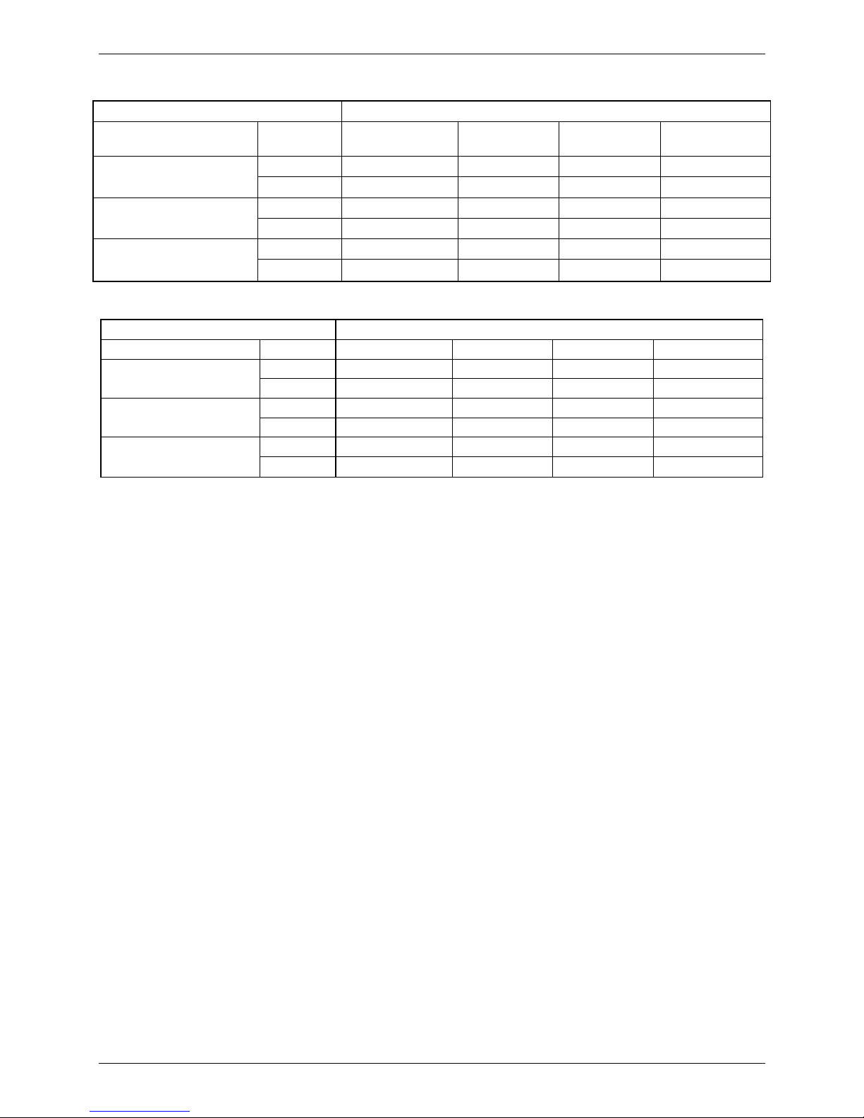
7.2 Heating Capacity
MCA-12HRN1
Heating Outdoor conditions
Indoor Conditions (DB) (kW) 24/18ºC DB/WB 7/6ºC DB/WB 2/1ºC DB/WB -5/-6ºC DB/WB
15ºC
TC
5.20 4.20 3.44 3.12
Input
1.13 0.98 0.84 0.79
20ºC
TC
5.04
4.00
3.24 3.04
Input
1.24
1.05
0.92 0.85
27ºC
TC
4.72 3.76 3.04 2.96
Input
1.31 1.13 1.00 0.92
MCA-18HRN1
Heating Outdoor conditions
Indoor Conditions (DB) (kW) 24/18ºC DB/WB 7/6ºC DB/WB 2/1ºC DB/WB -5/-6ºC DB/WB
15ºC
TC
7.80 6.30 5.16 4.68
Input
2.05 1.77 1.52 1.43
20ºC
TC
7.56
6.00
4.86 4.56
Input
2.24
1.90
1.67 1.54
27ºC
TC
7.08 5.64 4.56 4.44
Input
2.38 2.05 1.81 1.67
Remark:
TC: Total capacity ; kW
SC: Sensible heat capacity ; kW
Input: Input power ; kW
Page 18
Electric Characteristics MCAC-UTSM-2008-11
16 Indoor Units
8. Electric Characteristics
Model
Indoor Units Power Supply Indoor Fan Motor
Hz Voltage
Min. Max. MCA MFA kW FLA
MCA-12HRN1 50 220-240V 198V 254V 0.33 25 0.045 0.264
MCA-18HRN1 50 220-240V 198V 254V 0.33 25 0.045 0.264
Remark:
MCA: Min. Current Amps. (A)
MFA: Max. Fuse Amps. (A)
KW: Fan Motor Rated Output (kW)
FLA: Full Load Amps. (A)
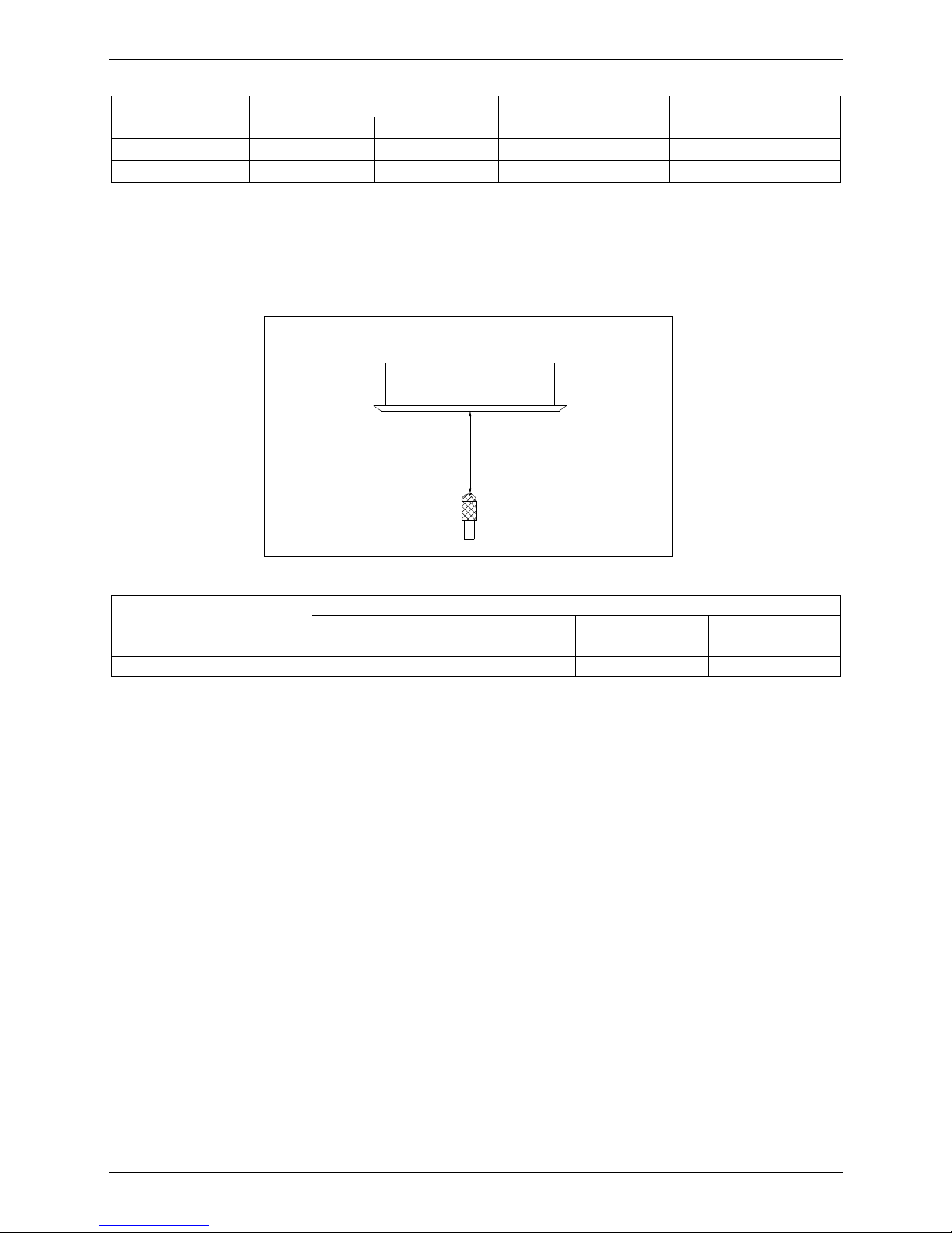
9. Sound Levels
1.0m
FOUR-WAY CASSETTE TYPE
Microphone
Model
Noise level dB(A)
H M L
MCA-12HRN1 41 38 35
MCA-18HRN1 42.5 39.4 35.8
Page 19
MCAC-UTSM-2008-11 Exploded View
Indoor Units 17
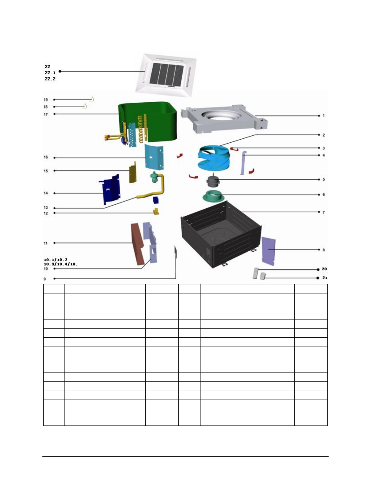
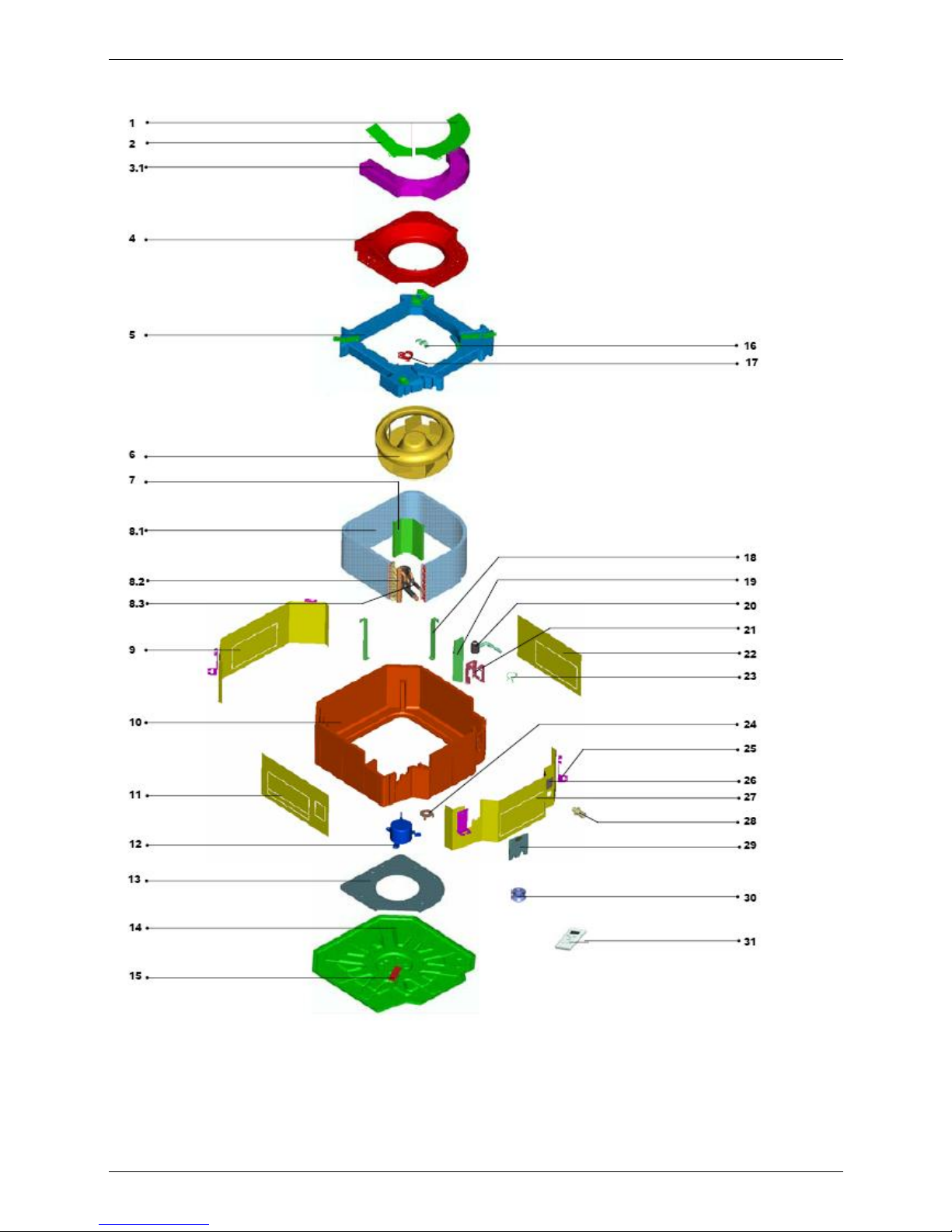
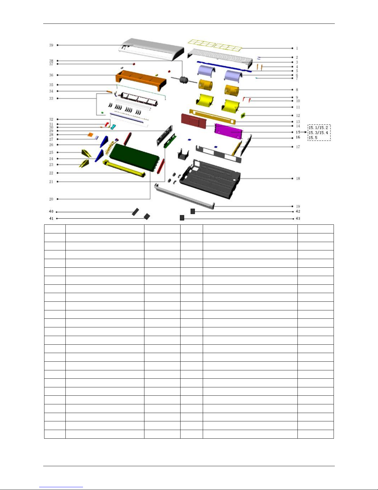
10. Exploded View
MCA-12HRN1 MCA-18HRN1
No. Part Name Quantity No. Part Name Quantity
1 Drainage pan ass'y 1 11 E-Part box cover 1
2 Centrifugal fan 1 12 Drain pump Holder 1
3 Installation bracket 4 13 Drain pump 1
4 Evaporator fixing hanger 1 14 Right clapboard ass'y 1
5 Motor 1 15 Partition board 1
6 Motor base 1 16 Evaporator fixing board ass'y 1
7 Base ass'y 1 17 Evaporator ass'y 1
8 Board 1 18 Evaporator temp. sensor ass'y 1
9 Sealed board ass'y 1 19 Room temp. sensor ass'y 1
10 E-part box ass'y 1 20 Remote controller 1
10.1 Main controller ass'y 1 21 Remote controller holder 1
10.2 Motor capacitor 1 22 Panel ass'y 1
10.3 Wire joint, 7p 1 22.1 Swing motor 1
10.4 Wire joint 1 22.2 Display board 1
10.5 Transformer 1
10.5
Page 20
Accessories MCAC-UTSM-2008-11
18 Indoor Units
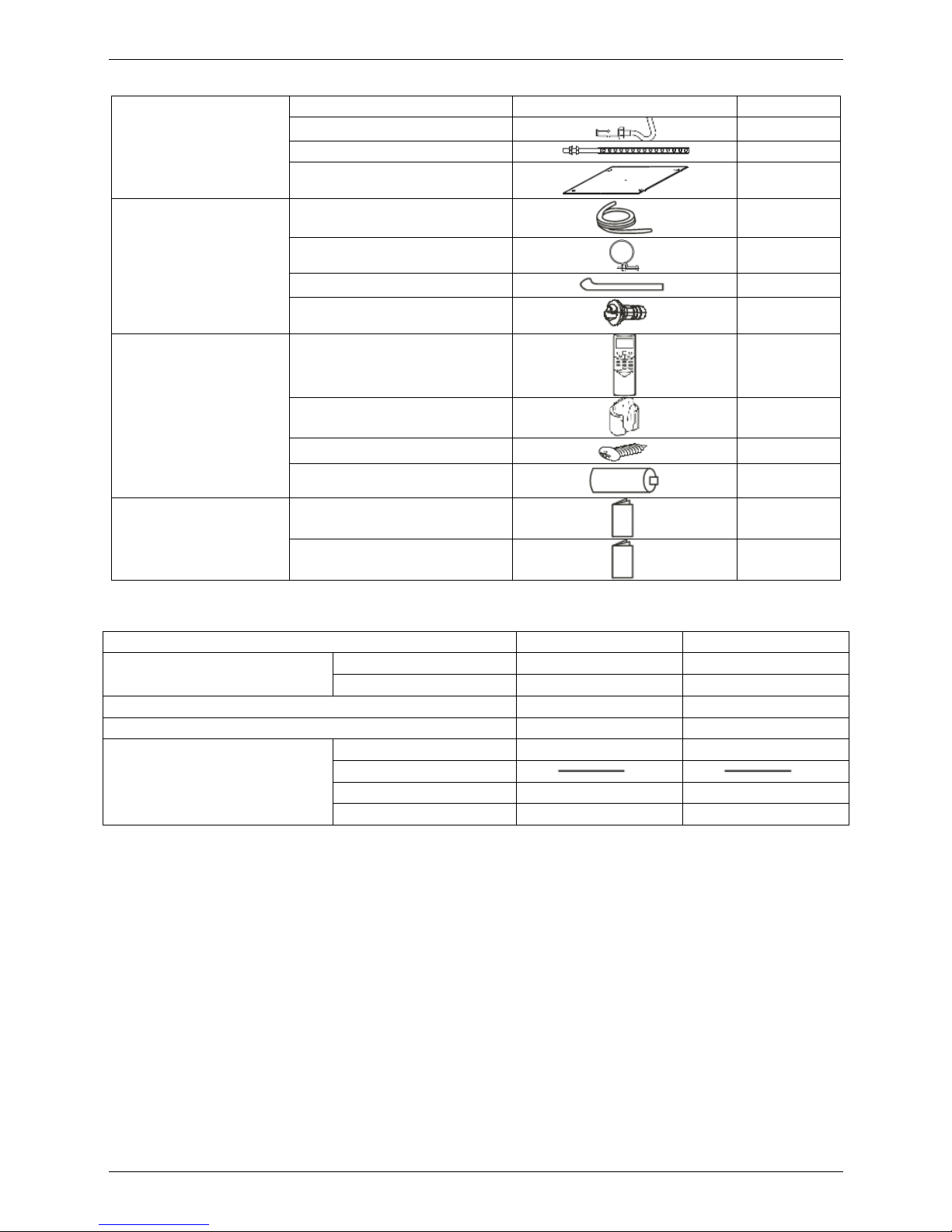
11. Accessories
Installation fittings
Name Shape Quantity
1. Expansible hook
4
2. Installation hook
4
3. Installation paper board
1
Drainpipe Fittings
4. Out-let pipe sheath
1
5. Out-let pipe clasp
1
6. Tightening band
20
7. Drain joint
1
Remote controller & Its
holder
8. Remote controller
1
9. Remote controller holder
1
10. Mounting screw(ST2.9×10-C-
H)
2
11. Alkaline dry batteries (AM4)
2
Others
12. Owner's manual
1
13. Installation manual
1
12. The Specification of Power
Type MCA-12HRN1 MCA-18HRN1
Power
Phase 1-phase 1-phase
Frequency and Voltage 220-240V, 50Hz 220-240V, 50Hz
Circuit Breaker/ Fuse (A) 40/25 40/25
Indoor Unit Power Wiring (mm2) 3×2.5 3×2.5
Indoor/Outdoor Connecting Wiring
2.5 2.5 2.5
Outdoor Unit Power Wiring
Strong Electric Signal 5×2.5 5×2.5
Weak Electric Signal 1-core shield wire 1×0.5 1-core shield wire 1×0.5
Page 21
MCAC-UTSM-2008-11 Field Wiring
Indoor Units 19
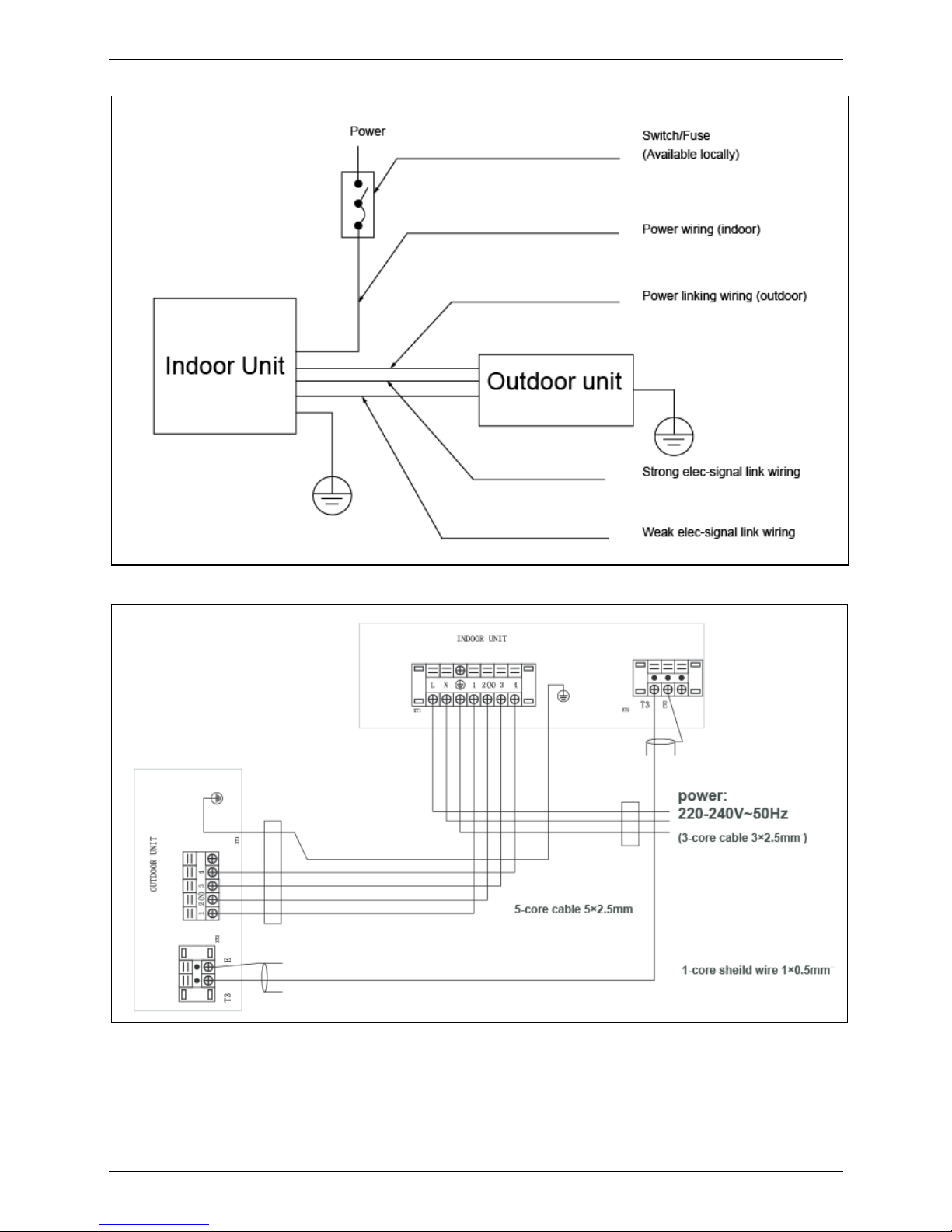
13. Field Wiring
MCA-12HRN1
Page 22
Field Wiring MCAC-UTSM-2008-11
20 Indoor Units
MCA-18HRN1
Page 23

MCAC-UTSM-2008-11 Four-way Cassette Type
Indoor Units 21
Four-way Cassette Type
1. Features .................................................................................................... 22
2. Specifications .......................................................................................... 24
3. Dimensions .............................................................................................. 27
4. Service Space .......................................................................................... 28
5. Wiring Diagrams ...................................................................................... 29
6. Air Velocity and Temperature Distributions .......................................... 31
7. Capacity Tables ........................................................................................ 32
8. Electric Characteristics ........................................................................... 38
9. Sound Levels ........................................................................................... 38
10. Exploded View ....................................................................................... 39
11. Accessories ............................................................................................ 51
12. The Specification of Power ................................................................... 51
13. Field Wiring ............................................................................................ 52
Page 24
Features MCAC-UTSM-2008-11
22 Indoor Units
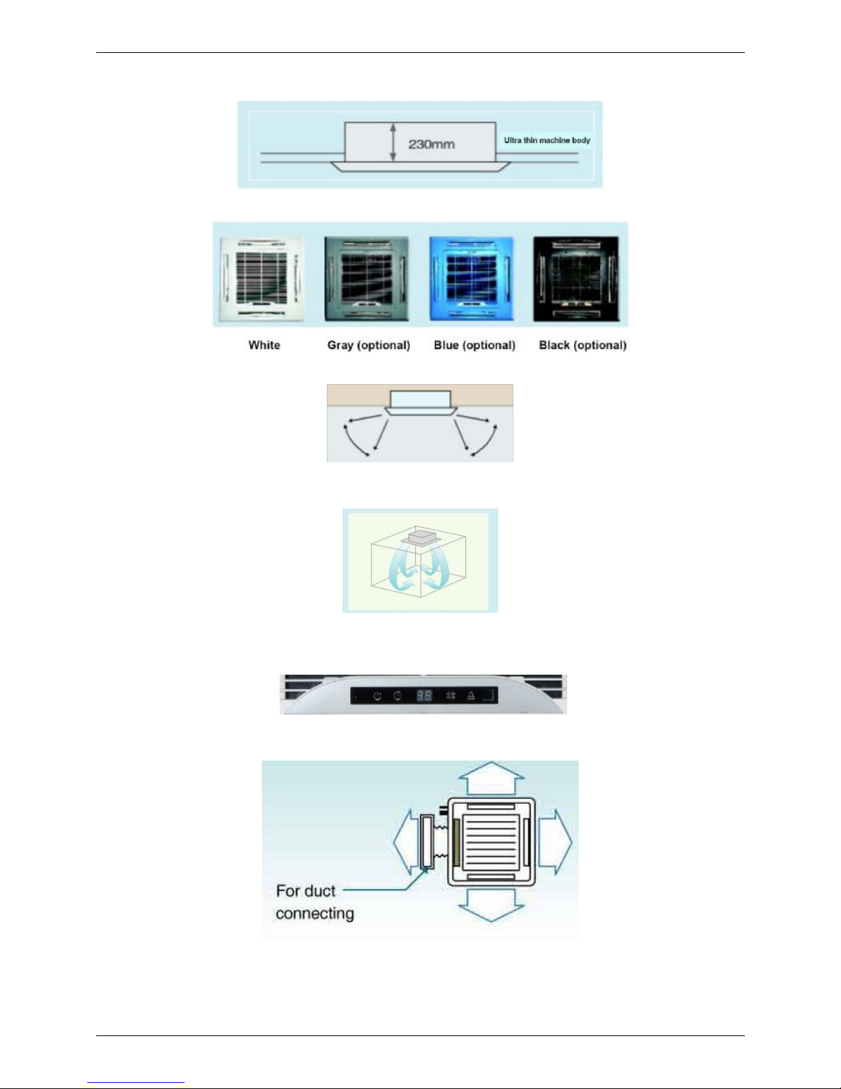
1. Features
(1) Ultra thin machine body to easy installation and maintenance. 24K:230mm, 30-48K:300mm.
(2) Different color panels to choose: White, Gray, Blue, Black
(3) The swing angle of the first louver are 40~42 degrees and the second louver are 37~38 degrees.
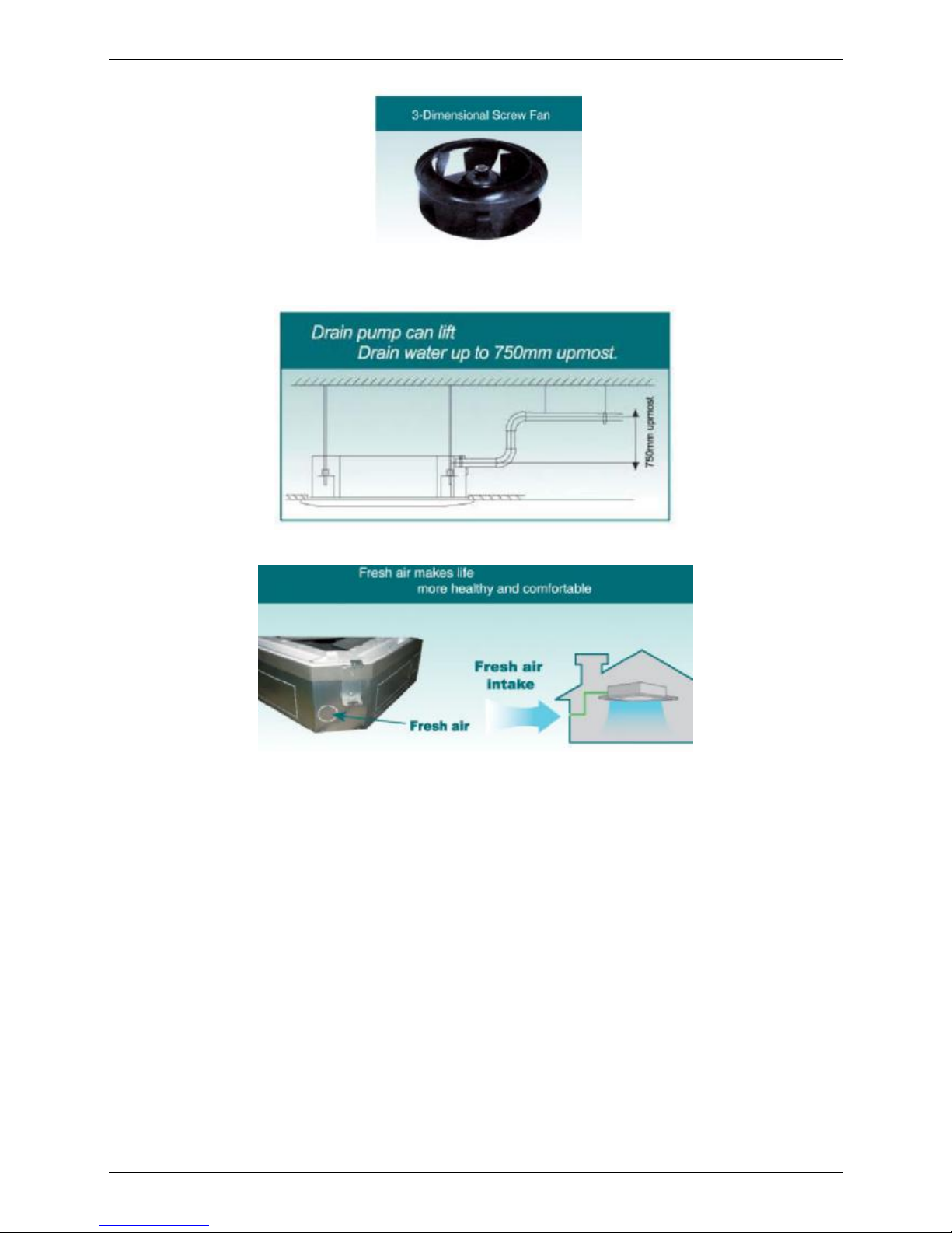
(4) 4 speeds available, optional super high fan speed design, suitable for the large building over 3m high.
(5) Adding digital tube displaying on the display board. LED can display the Error Code to make the
malfunction checking easier.
(6) Reserve spaces for air side-outlet, it is available to connect duct pipe hence Air supplying from the four
sides to nearby small room.
Page 25
MCAC-UTSM-2008-11 Features
Indoor Units 23
(7) Stylish design is harmonious with any interior decoration and creates and elegant environment.
(8) Built-in water pump with 750mm pumping head.
(9) Fresh air makes life more healthy and comfortable.
Page 26

Specifications MCAC-UTSM-2008-11
24 Indoor Units
2. Specifications
Model MCC-24HRN1 MCC-30HRN1
Code 220042500390 220042600250
Power supply V-ph-Hz
220~240-1-50 220~240-1-50
Cooling
Capacity kW 7.1 9.0
Input W 2700 3500
Heating
Capacity kW 7.6 9.5
Input W 2800 3600
Indoor fan motor
Model YDK80-6E YDK90-6E
Brand Welling Welling
Input W 120/110/100/90 165/143/116/100
Capacitor uF 3.5uF/450V 3.5uF/450V
Speed(Hi/Mi/Lo) r/min 800/670/550/400 840/770/640/550
Indoor coil
Number of rows 2 2
Tube pitch(a)×row pitch(b) mm 21×13.37 21×13.37
Fin spacing mm 1.5 1.5
Fin type (code) Hydrophilic aluminum Hydrophilic aluminium
Tube outside dia.and type mm φ7 Inner grooved copper tube φ7 Inner grooved copper tube
Coil length × height × width
mm 1959.4×168×26.74 1959.4×252×26.74
Number of circuits 16
12
Indoor air flow (Hi/Mi/Lo) m3/h 1220/1010/822
1538/1296/1124
Indoor noise level (sound pressure) dB(A) 48/44/40 50/46//42
Indoor unit
Dimension (W×H×D)(body) mm 840×230×840 840×300×840
Packing (W×H×D)(body) mm 955×247×955 955×317×955
Dimension (W×H×D)(panel) mm 950×55×950 950×55×950
Packing (W×H×D)(panel) mm 1035×90×1035 1035×90×1035
Net/Gross weight(body) kg 29/36 35/42
Net/Gross weight(panel) kg 6/9 6/9
Refrigerant type R410A R410A
Design pressure MPa 4.4/2.6 4.4/2.6
Refrigerant piping Liquid side/Gas side mm φ9.5/φ15.9 φ12.7/φ19
Drainage water pipe diameter mm ODφ32 ODφ32
Connection wiring
Power wiring mm2 3×4.0 3×4.0
Strong electric signal wiring mm2 3×2.5 3×2.5
Weak electric signal wiring mm2 1-core shield wire 1×0.5 1-core shield wire 1×0.5
Controller R05/BGE(standard) R05/BGE(standard)
Operation temperature ℃ 17-30 17-30
Notes: 1. Nominal cooling capacities are based on the following conditions:
Indoor temp: 27°CDB, 19°CWB; Outdoor temp: 35°CDB;
2. Nominal heating capacities are based on the following conditions:
Indoor temp: 20°CDB; Outdoor temp: 7°CDB, 6°CWB;
3. Actual noise level may differ, depending on the room structure, etc, since these noise values are from an anechoic
room.
Page 27
MCAC-UTSM-2008-11 Specifications
Indoor Units 25
Model MCC-30HRN1-R MCC-36HRN1
Code 220042600270 220042700210
Power supply V-ph-Hz
380~415-3-50 220~240-1-50
Cooling
Capacity kW 9.0 10.5
Input W 3500
3850
Heating
Capacity kW 9.5 12.0
Input W 3700
4050
Indoor fan motor
Model YDK90-6E YDK90-6E
Brand Welling Welling
Input W 165/143/116/100 165/143/116/100
Capacitor uF 3.5uF/450V 3.5uF/450V
Speed(Hi/Mi/Lo) r/min 840/770/640/550 840/770/640/550
Indoor coil
Number of rows 2 2
Tube pitch(a)×row pitch(b) mm 21×13.37 21×13.37
Fin spacing mm 1.5 1.5
Fin type (code) Hydrophilic aluminum Hydrophilic aluminum
Tube outside dia.and type mm φ7 Inner grooved copper tube φ7 Inner grooved copper tube
Coil length × height × width
mm 1959.4×252×26.74 1959.4×252×26.74
Number of circuits 12 12
Indoor air flow (Hi/Mi/Lo) m3/h 1538/1296/1124 1538/1296/1124
Indoor noise level (sound pressure) dB(A) 50/46//42 50/46//42
Indoor unit
Dimension (W×H×D)(body) mm 840×300×840 840×300×840
Packing (W×H×D)(body) mm 955×317×955 955×317×955
Dimension (W×H×D)(panel) mm 950×55×950 950×55×950
Packing (W×H×D)(panel) mm 1035×90×1035 1035×90×1035
Net/Gross weight(body) kg 35/42 35/42
Net/Gross weight(panel) kg 6/9 6/9
Refrigerant type R410A R410A
Design pressure MPa 4.4/2.6 4.4/2.6
Refrigerant piping Liquid side/Gas side mm φ12.7/φ19 φ12.7/φ19
Drainage water pipe diameter mm ODφ32 ODφ32
Connection wiring
Power wiring mm2 5×2.5 3×4.0
Strong electric signal wiring mm2 3×1.0 3×2.5
Weak electric signal wiring mm2 — 1-core shield wire 1×0.5
Controller R05/BGE(standard) R05/BGE(standard)
Operation temperature
℃
17-30 17-30
Notes: 1. Nominal cooling capacities are based on the following conditions:
Indoor temp: 27°CDB, 19°CWB; Outdoor temp: 35°CDB;
2. Nominal heating capacities are based on the following conditions:
Indoor temp: 20°CDB; Outdoor temp: 7°CDB, 6°CWB;
3. Actual noise level may differ, depending on the room structure, etc, since these noise values are from an anechoic
room.
Page 28

Specifications MCAC-UTSM-2008-11
26 Indoor Units
Model MCC-36HRN1-R MCC-48HRN1-R
Code 220042700230 220042800310
Power supply V-ph-Hz
380~415-3-50 380~415-3-50
Cooling
Capacity kW 10.5 14
Input W
3850
4881
Heating
Capacity kW 12.0 15
Input W
4100
4941
Indoor fan motor
Model YDK90-6E YDK90-6E
Brand Welling Welling
Input W 165/143/116/100 165/143/116/100
Capacitor uF 3.5uF/450V 3.5uF/450V
Speed(Hi/Mi/Lo) r/min 840/770/640/550 840/770/640/550
Indoor coil
Number of rows 2 2
Tube pitch(a)×row pitch(b) mm 21×13.37 21×13.37
Fin spacing mm 1.5 1.5
Fin type (code) Hydrophilic aluminum Hydrophilic aluminum
Tube outside dia.and type mm φ7 Inner grooved copper tube φ7 Inner grooved copper tube
Coil length × height × width
mm 1959.4×252×26.74 1959.4×252×26.74
Number of circuits 12 12
Indoor air flow (Hi/Mi/Lo) m3/h 1538/1296/1124 1538/1296/1124
Indoor noise level (sound pressure) dB(A) 50/46//42 50/46//42
Indoor unit
Dimension (W×H×D)(body) mm 840×300×840 840×300×840
Packing (W×H×D)(body) mm 955×317×955 955×317×955
Dimension (W×H×D)(panel) mm 950×55×950 950×55×950
Packing (W×H×D)(panel) mm 1035×90×1035 1035×90×1035
Net/Gross weight(body) kg 35/42 35/42
Net/Gross weight(panel) kg 6/9 6/9
Refrigerant type R410A R410A
Design pressure MPa 4.4/2.6 4.4/2.6
Refrigerant piping Liquid side/Gas side mm φ12.7/φ19 φ12.7/φ19
Drainage water pipe diameter mm ODφ32 ODφ32
Connection wiring
Power wiring mm2 5×2.5 5×2.5
Strong electric signal wiring mm2 3×1.0 3×1.0
Weak electric signal wiring mm2 — —
Controller R05/BGE(standard) R05/BGE(standard)
Operation temperature
℃
17-30 17-30
Notes: 1. Nominal cooling capacities are based on the following conditions:
Indoor temp: 27°CDB, 19°CWB; Outdoor temp: 35°CDB;
2. Nominal heating capacities are based on the following conditions:
Indoor temp: 20°CDB; Outdoor temp: 7°CDB, 6°CWB;
3. Actual noise level may differ, depending on the room structure, etc, since these noise values are from an anechoic
room.
Page 29
MCAC-UTSM-2008-11 Dimensions
Indoor Units 27
3. Dimensions
3.1 MCC-24HRN1
3.2 MCC-30HRN1 MCC-30HRN1-R MCC-36HRN1 MCC-36HRN1-R MCC-48HRN1-R
Page 30
Service Space MCAC-UTSM-2008-11
28 Indoor Units
4. Service Space
The indoor unit should be installed in a location that meets the following requirements:
● There is enough room for installation and maintenance.
● The ceiling is horizontal, and its structure can endure the weight of the indoor unit.
● The outlet and the inlet are not impeded, and the influence of external air is the least.
● The air flow can reach throughout the room.
● The connecting pipe and drainpipe could be extracted out easily.
● There is no direct radiation from heaters.
Page 31

MCAC-UTSM-2008-11 Wiring Diagrams
Indoor Units 29
5. Wiring Diagrams
5.1 MCC-24HRN1 MCC-30HRN1 MCC-36HRN1
Page 32

Wiring Diagrams MCAC-UTSM-2008-11
30 Indoor Units
5.2 MCC-30HRN1-R MCC-36HRN1-R MCC-48HRN1-R
Page 33

MCAC-UTSM-2008-11 Air Velocity and Temperature Distributions
Indoor Units 31
6. Air Velocity and Temperature Distributions
Airflow velocity
Temperature
Page 34

Capacity Tables MCAC-UTSM-2008-11
32 Indoor Units
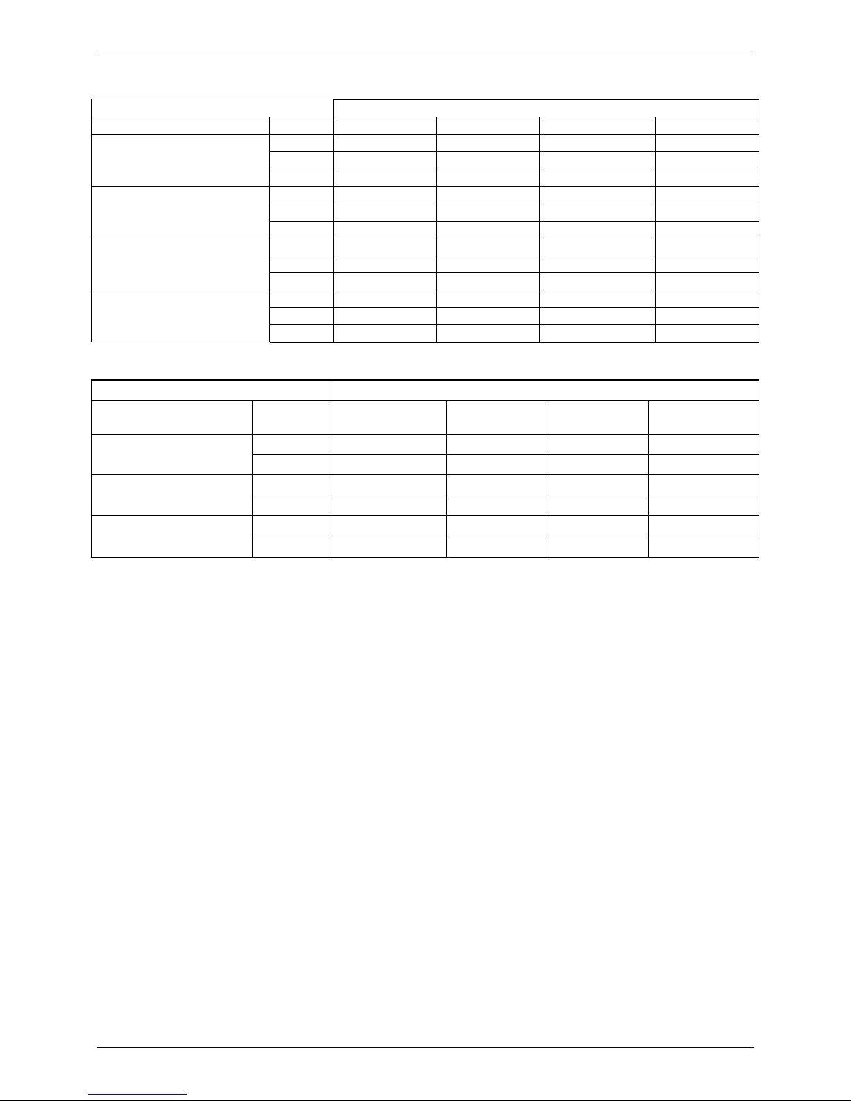
7. Capacity Tables
MCC-24HRN1
Cooling
Cooling Outdoor conditions (DB)
Indoor Conditions (kW) 21ºC 28ºC 35ºC 43ºC
21/15ºC DB/WB
TC 7.31 6.96 6.60 6.32
SC 5.41 5.36 5.28 5.31
Input 2.24 2.43 2.54 2.62
24/17ºC DB/WB
TC 7.53 7.17 6.82 6.39
SC 5.64 5.59 5.52 5.37
Input 2.38 2.54 2.65 2.78
27/19ºC DB/WB
TC 7.67 7.31 7.10 6.60
SC 5.67 5.63 5.54 5.41
Input 2.43 2.57 2.70 2.84
32/23ºC DB/WB
TC 7.81 7.53 7.38 6.82
SC 6.64 6.55 6.50 6.34
Input 2.54 2.65 2.84 2.94
Heating
Heating Outdoor conditions
Indoor Conditions (DB) (kW)
24/18ºC
DB/WB
7/6ºC
DB/WB
2/1ºC
DB/WB
-5/-6ºC
DB/WB
15ºC
TC 9.88 7.98 6.54 5.93
Input 3.02 2.60 2.24 2.10
20ºC
TC 9.58 7.60 6.16 5.78
Input 3.30 2.80 2.46 2.27
27ºC
TC 8.97 7.14 5.78 5.62
Input 3.50 3.02 2.66 2.46
Remark:
TC : Total capacity ; kW
SC: Sensible heat capacity ; kW
Input: Input power ; kW
Page 35

MCAC-UTSM-2008-11 Capacity Tables
Indoor Units 33
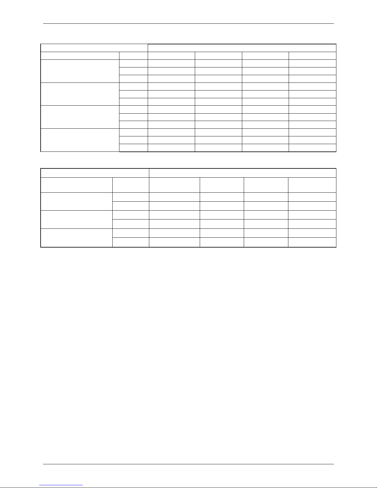
MCC-30HRN1
Cooling
Cooling Outdoor conditions (DB)
Indoor Conditions (kW) 21ºC 28ºC 35ºC 43ºC
21/15ºC DB/WB
TC 9.27 8.82 8.37 8.01
SC 6.86 6.79 6.70 6.73
Input 2.91 3.15 3.29 3.40
24/17ºC DB/WB
TC 9.54 9.09 8.64 8.10
SC 7.16 7.09 7.00 6.80
Input 3.08 3.29 3.43 3.61
27/19ºC DB/WB
TC 9.72 9.27 9.00 8.37
SC 7.19 7.14 7.02 6.86
Input 3.15 3.33 3.50 3.68
32/23ºC DB/WB
TC 9.90 9.54 9.36 8.64
SC 8.42 8.30 8.24 8.04
Input 3.29 3.43 3.68 3.82
Heating
Heating Outdoor conditions
Indoor Conditions (DB) (kW) 24/18ºC DB/WB 7/6ºC DB/WB 2/1ºC DB/WB -5/-6ºC DB/WB
15ºC
TC
12.35 9.98 8.17 7.41
Input
3.89 3.35 2.88 2.70
20ºC
TC
11.97
9.50
7.70 7.22
Input
4.25
3.60
3.17 2.92
27ºC
TC
11.21 8.93 7.22 7.03
Input
4.50 3.89 3.42 3.17
Remark:
TC : Total capacity ; kW
SC: Sensible heat capacity ; kW
Input: Input power ; kW
Page 36
Capacity Tables MCAC-UTSM-2008-11
34 Indoor Units
MCC-30HRN1-R
Cooling
Cooling Outdoor conditions (DB)
Indoor Conditions (kW) 21ºC 28ºC 35ºC 43ºC
21/15ºC DB/WB
TC 9.27 8.82 8.37 8.01
SC 6.86 6.79 6.70 6.73
Input 2.91 3.15 3.29 3.40
24/17ºC DB/WB
TC 9.54 9.09 8.64 8.10
SC 7.16 7.09 7.00 6.80
Input 3.08 3.29 3.43 3.61
27/19ºC DB/WB
TC 9.72 9.27 9.00 8.37
SC 7.19 7.14 7.02 6.86
Input 3.15 3.33 3.50 3.68
32/23ºC DB/WB
TC 9.90 9.54 9.36 8.64
SC 8.42 8.30 8.24 8.04
Input 3.29 3.43 3.68 3.82
Heating
Heating Outdoor conditions
Indoor Conditions (DB) (kW) 24/18ºC DB/WB 7/6ºC DB/WB 2/1ºC DB/WB -5/-6ºC DB/WB
15ºC
TC
12.35 9.98 8.17 7.41
Input
4.00 3.44 2.96 2.78
20ºC
TC
11.97
9.50
7.70 7.22
Input
4.37
3.70
3.26 3.00
27ºC
TC
11.21 8.93 7.22 7.03
Input
4.63 4.00 3.52 3.26
Remark:
TC : Total capacity ; kW
SC: Sensible heat capacity ; kW
Input: Input power ; kW
Page 37
MCAC-UTSM-2008-11 Capacity Tables
Indoor Units 35
MCC-36HRN1
Cooling
Cooling Outdoor conditions (DB)
Indoor Conditions (kW) 21ºC 28ºC 35ºC 43ºC
21/15ºC DB/WB
TC 10.82 10.29 9.77 9.35
SC 8.00 7.92 7.81 7.85
Input 3.20 3.47 3.62 3.73
24/17ºC DB/WB
TC 11.13 10.61 10.08 9.45
SC 8.35 8.27 8.16 7.94
Input 3.39 3.62 3.77 3.97
27/19ºC DB/WB
TC 11.34 10.82 10.50 9.77
SC 8.39 8.33 8.19 8.01
Input 3.47 3.66 3.850 4.04
32/23ºC DB/WB
TC 11.55 11.13 10.92 10.08
SC 9.82 9.68 9.61 9.37
Input 3.62 3.77 4.04 4.20
Heating
Heating Outdoor conditions
Indoor Conditions (DB) (kW) 24/18ºC DB/WB 7/6ºC DB/WB 2/1ºC DB/WB -5/-6ºC DB/WB
15ºC
TC
15.60 12.60 10.32 9.36
Input
4.37 3.77 3.24 3.04
20ºC
TC
15.12
12.00
9.72 9.12
Input
4.78
4.05
3.56 3.28
27ºC
TC
14.16 11.28 9.12 8.88
Input
5.06 4.37 3.85 3.56
Remark:
TC : Total capacity ; kW
SC: Sensible heat capacity ; kW
Input: Input power ; kW
Page 38

Capacity Tables MCAC-UTSM-2008-11
36 Indoor Units
MCC-36HRN1-R
Cooling
Cooling Outdoor conditions (DB)
Indoor Conditions (kW) 21ºC 28ºC 35ºC 43ºC
21/15ºC DB/WB
TC 10.82 10.29 9.77 9.35
SC 8.00 7.92 7.81 7.85
Input 3.20 3.47 3.62 3.73
24/17ºC DB/WB
TC 11.13 10.61 10.08 9.45
SC 8.35 8.27 8.16 7.94
Input 3.39 3.62 3.77 3.97
27/19ºC DB/WB
TC 11.34 10.82 10.50 9.77
SC 8.39 8.33 8.19 8.01
Input 3.47 3.66 3.850 4.04
32/23ºC DB/WB
TC 11.55 11.13 10.92 10.08
SC 9.82 9.68 9.61 9.37
Input 3.62 3.77 4.04 4.20
Heating
Heating Outdoor conditions
Indoor Conditions (DB) (kW) 24/18ºC DB/WB 7/6ºC DB/WB 2/1ºC DB/WB -5/-6ºC DB/WB
15ºC
TC
15.60 12.60 10.32 9.36
Input
4.43 3.81 3.28 3.08
20ºC
TC
15.12
12.00
9.72 9.12
Input
4.84
4.10
3.61 3.32
27ºC
TC
14.16 11.28 9.12 8.88
Input
5.13 4.43 3.90 3.61
Remark:
TC : Total capacity ; kW
SC: Sensible heat capacity ; kW
Input: Input power ; kW
Page 39

MCAC-UTSM-2008-11 Capacity Tables
Indoor Units 37
MCC-48HRN1-R
Cooling
Cooling Outdoor conditions (DB)
Indoor Conditions (kW) 21ºC 28ºC 35ºC 43ºC
21/15ºC DB/WB
TC 14.42 13.72 13.02 12.46
SC 10.67 10.56 10.42 10.47
Input 4.05 4.39 4.59 4.73
24/17ºC DB/WB
TC 14.84 14.14 13.44 12.60
SC 11.13 11.03 10.89 10.58
Input 4.30 4.59 4.78 5.03
27/19ºC DB/WB
TC 15.12 14.42 14.00 13.02
SC 11.19 11.10 10.92 10.68
Input 4.39 4.64 4.881 5.13
32/23ºC DB/WB
TC 15.40 14.84 14.56 13.44
SC 13.09 12.91 12.81 12.50
Input 4.59 4.78 5.13 5.32
Heating
Heating Outdoor conditions
Indoor Conditions (DB) (kW) 24/18ºC DB/WB 7/6ºC DB/WB 2/1ºC DB/WB -5/-6ºC DB/WB
15ºC
TC 19.50 15.75 12.90 11.70
Input 5.34 4.60 3.95 3.71
20ºC
TC 18.90 15.00 12.15 11.40
Input 5.83 4.941 4.35 4.00
27ºC
TC 17.70 14.10 11.40 11.10
Input 6.18 5.34 4.69 4.35
Remark:
TC : Total capacity ; kW
SC: Sensible heat capacity ; kW
Input: Input power ; kW
Page 40

Electric Characteristics MCAC-UTSM-2008-11
38 Indoor Units
8. Electric Characteristics
Model
Indoor Units Power Supply Indoor Fan Motor
Hz Voltage
Min. Max. MCA MFA kW FLA
MCC-24HRN1 50 220-240V 198V 254V 0.7 25 0.065 0.56
MCC-30HRN1 50 220-240V 198V 254V 0.955 25 0.090 0.8
MCC-30HRN1-R 50 380-415V 342V 418V 0.955 15 0.090 0.8
MCC-36HRN1 50 220-240V 198V 254V 0.955 25 0.090 0.8
MCC-36HRN1-R 50 380-415V 342V 418V 0.955 15 0.090 0.8
MCC-48HRN1-R 50 380-415V 342V 418V 0.955 15 0.090 0.8
Remark:
MCA: Min. Current Amps. (A)
MFA: Max. Fuse Amps. (A)
KW: Fan Motor Rated Output (kW)
FLA: Full Load Amps. (A)
9. Sound Levels
1.0m
FOUR-WAY CASSETTE TYPE
Microphone
Model
Noise level dB(A)
H M L
MCC-24HRN1 48 44 40
MCC-30HRN1/MCC-30HRN1-R
50 46 42
MCC-36HRN1/MCC-36HRN1-R
50 46 42
MCC-48HRN1-R 50 46 42
Page 41

MCAC-UTSM-2008-11 Exploded View
Indoor Units 39
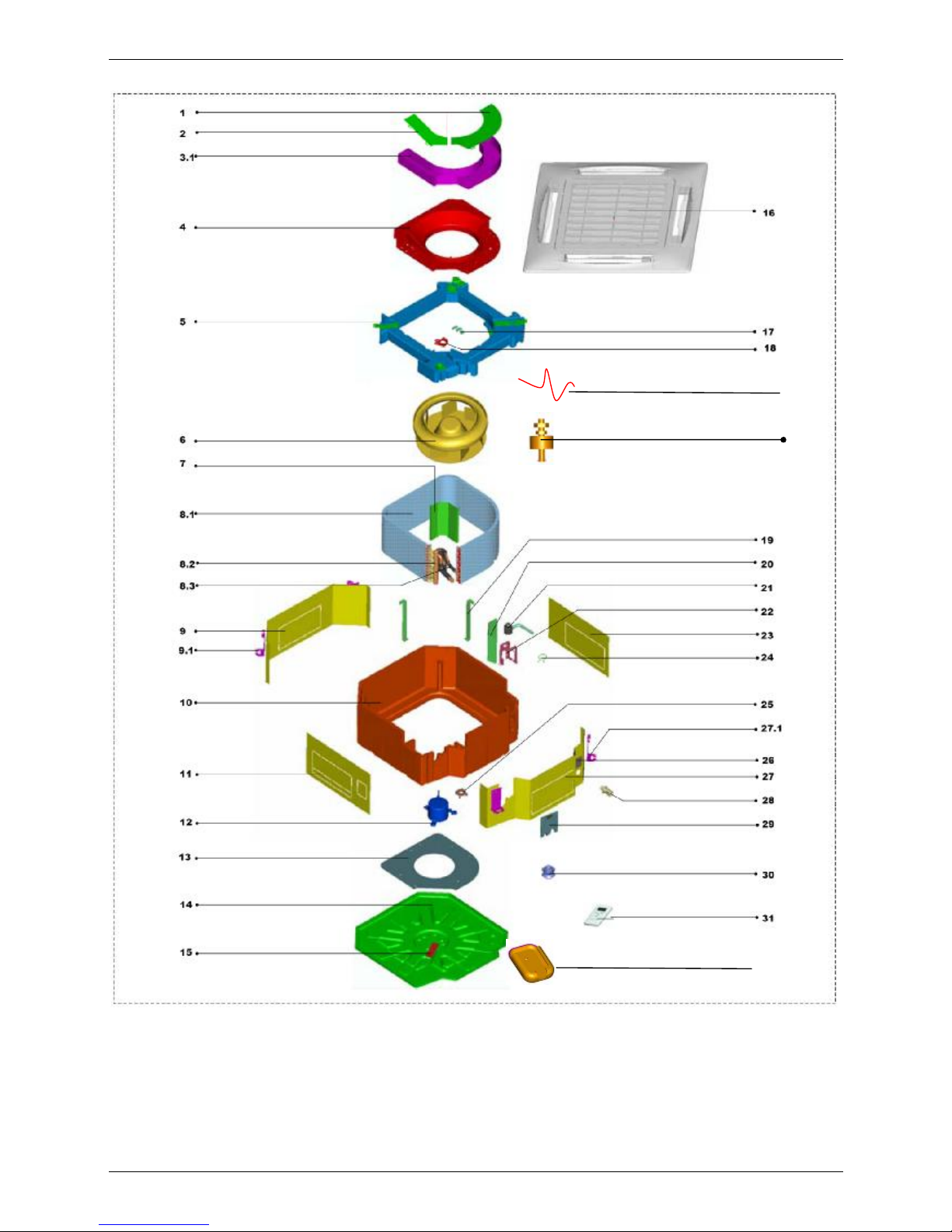
10. Exploded View
10.1 MCC-24HRN1
33
Page 42

Exploded View MCAC-UTSM-2008-11
40 Indoor Units
No. Part Name Quantity No. Part Name Quantity
1 Electricity control box coping I 1 12 Motor 1
2 Electricity control box coping II 1 13 Base 1
3 E-part box ass'y 1 14 Wire clamp 1
3.1 E-part box 1 15 Panel 1
3.2 Transformer 1 16 Wire clamp 1
3.3 Room temp. sensor ass'y 1 17 Wire clip 1
3.4 Motor capacitor 1 18 Evaporator fixing hanger 3
3.5 Main controller 1 19 Water pump board 1
3.6 Wire joint 1 20 Drain pump 1
3.7 Wire joint, 3p 1 21 Installation bracket ass'y 1
4 Air guide ring ass'y 1 22 Board ass'y 1
5 Foam ass'y 1 23 Water pipe clamp 1
6 Fan ass'y 1 24 Fan clip 1
7 Evaporator fixing board 1 25 Water cover ass'y 1
8 Evaporator ass'y 1 26 Board ass'y 1
8.1 Evaporator 1 26.1 Hook 2
8.2 Evaporator output pipe ass'y 1 27 Water pipe 1
8.3 Evaporator input pipe ass'y 1 28 Sealed board ass'y 1
8.4 Sleeve 1 29 Pump rubber washer 3
9 Board ass'y 1 30 Remote controller 1
9.1 Hook 2 31 Installation bracket 1
10 Foam ass'y 1 32 Evaporator temp. sensor 1
11 Board ass'y 1 33 Water-level sensor ass’y 1
Page 43

MCAC-UTSM-2008-11 Exploded View
Indoor Units 41
10.2 MCC-30HRN1
Page 44

Exploded View MCAC-UTSM-2008-11
42 Indoor Units
No.
Part Name Quantity No. Part Name Quantity
1 Electric control box head cover I 1 13 Base pan seat 1
2 Electric control box head cover II 1 14 Base pan welded assembly 1
3
Electric control box assembly of indoor
unit
1 15 Plate, wire 1
3.1 Electric control box welded assembly 1 16 Tandem, wire 1
3.2 Voltage transformer 1 17 Bipitch wire clip 1
3.3 Indoor temp. sensor subassembly 1 18 Evaporator fixing hook 3
3.4 Capacitor 1 19 Water pump baffle plate 1
3.5
Four sides air outlet indoor main
control plate
1 20 Water drain pump subassembly 1
4 Air inducting coils subassembly 1 21
Water pump installation bracket
subassembly
1
5 Foam subassembly ,drip tray 1 22 Front barrier IV subassembly 1
6 Fan assembly 1 23 Water pump pumping pipe grommet 1
7 Evaporator fixing board 1 24 Fan fins 1
8 Evaporator assembly 1 25 Install lifting lug 4
8.1 Evaporator 1 26 Water finder cover subassembly 1
8.2 Evaporator output tube assembly 1 27 Front barrier III subassembly 1
8.3 Evaporator filter assembly 1 28 Water pumping connect pipe 1
8.4 Barrel 1 29 Exhalant tube seal plate subassembly 1
9 Front barrier I subassembly 1 30 Water pump's rubber pad 1
10 Foam seat subassembly 1 31 Remote controller 1
11 Front barrier II subassembly 1 32 Bracket, remote controller 1
12 Asynchronous dynamo 1 33 Front panel 1
Page 45

MCAC-UTSM-2008-11 Exploded View
Indoor Units 43
10.3 MCC-30HRN1 -R
Page 46

Exploded View MCAC-UTSM-2008-11
44 Indoor Units
No.
Part Name Quantity No. Part Name Quantity
1 Electric control box head cover I 1 13 Base pan seat 1
2 Electric control box head cover II 1 14 Base pan welded assembly 1
3
Electric control box assembly of indoor
unit
1 15 Plate, wire 1
3.1 Electric control box welded assembly 1 16 Tandem, wire 1
3.2 Voltage transformer 1 17 Bipitch wire clip 1
3.3 Indoor temp. sensor subassembly 1 18 Evaporator fixing hook 3
3.4 Capacitor 1 19 Water pump baffle plate 1
3.5
Four sides air outlet indoor main
control plate
1 20 Water drain pump subassembly 1
4 Air inducting coils subassembly 1 21
Water pump installation bracket
subassembly
1
5 Foam subassembly ,drip tray 1 22 Front barrier IV subassembly 1
6 Fan assembly 1 23 Water pump pumping pipe grommet 1
7 Evaporator fixing board 1 24 Fan fins 1
8 Evaporator assembly 1 25 Install lifting lug 4
8.1 Evaporator 1 26 Water finder cover subassembly 1
8.2 Evaporator output tube assembly 1 27 Front barrier III subassembly 1
8.3 Evaporator filter assembly 1 28 Water pumping connect pipe 1
8.4 Barrel 1 29 Exhalant tube seal plate subassembly 1
9 Front barrier I subassembly 1 30 water pump's rubber pad 1
10 Foam seat subassembly 1 31 Remote controller 1
11 Front barrier II subassembly 1 32 Bracket, remote controller 1
12 Asynchronous dynamo 1 33 Front panel 1
Page 47

MCAC-UTSM-2008-11 Exploded View
Indoor Units 45
10.4 MCC-36HRN1
Page 48

Exploded View MCAC-UTSM-2008-11
46 Indoor Units
No.
Part Name Quantity No. Part Name Quantity
1 Electric control box head cover I 1 13 Base pan seat 1
2 Electric control box head cover II 1 14 Base pan welded assembly 1
3
Electric control box assembly of indoor
unit
1 15 Plate, wire 1
3.1 Electric control box welded assembly 1 16 Tandem, wire 1
3.2 Voltage transformer 1 17 Bipitch wire clip 1
3.3 Indoor temp. sensor subassembly 1 18 Evaporator fixing hook 3
3.4 Capacitor 1 19 Water pump baffle plate 1
3.5
Four sides air outlet indoor main
control plate
1 20 Water drain pump subassembly 1
4 Air inducting coils subassembly 1 21
Water pump installation bracket
subassembly
1
5 Foam subassembly ,drip tray 1 22 Front barrier IV subassembly 1
6 Fan assembly 1 23 Water pump pumping pipe grommet 1
7 Evaporator fixing board 1 24 fan fins 1
8 Evaporator assembly 1 25 Install lifting lug 4
8.1 Evaporator 1 26 Water finder cover subassembly 1
8.2 Evaporator output tube assembly 1 27 Front barrier III subassembly 1
8.3 Evaporator filter assembly 1 28 Water pumping connect pipe 1
8.4 Barrel 1 29 Exhalant tube seal plate subassembly 1
9 Front barrier I subassembly 1 30 Water pump's rubber pad 1
10 Foam seat subassembly 1 31 Remote controller 1
11 Front barrier II subassembly 1 32 Bracket, remote controller 1
12 Asynchronous dynamo 1 33 Front panel 1
Page 49
MCAC-UTSM-2008-11 Exploded View
Indoor Units 47
10.5 MCC-36HRN1-R
Page 50

Exploded View MCAC-UTSM-2008-11
48 Indoor Units
No.
Part Name Quantity No. Part Name Quantity
1 Electric control box head cover I 1 13 Base pan seat 1
2 Electric control box head cover II 1 14 Base pan welded assembly 1
3
Electric control box assembly of indoor
unit
1 15 Plate, wire 1
3.1 Electric control box welded assembly 1 16 Tandem, wire 1
3.2 Voltage transformer 1 17 Bipitch wire clip 1
3.3 Indoor temp. sensor subassembly 1 18 Evaporator fixing hook 3
3.4 Capacitor 1 19 Water pump baffle plate 1
3.5
Four sides air outlet indoor main
control plate
1 20 Water drain pump subassembly 1
4 Air inducting coils subassembly 1 21
Water pump installation bracket
subassembly
1
5 Foam subassembly ,drip tray 1 22 Front barrier IV subassembly 1
6 Fan assembly 1 23 Water pump pumping pipe grommet 1
7 Evaporator fixing board 1 24 Fan fins 1
8 Evaporator assembly 1 25 Install lifting lug 4
8.1 Evaporator 1 26 Water finder cover subassembly 1
8.2 Evaporator output tube assembly 1 27 Front barrier III subassembly 1
8.3 Evaporator filter assembly 1 28 Water pumping connect pipe 1
8.4 Barrel 1 29 Exhalant tube seal plate subassembly 1
9 Front barrier I subassembly 1 30 Water pump's rubber pad 1
10 Foam seat subassembly 1 31 Remote controller 1
11 Front barrier II subassembly 1 32 Bracket, remote controller 1
12 Asynchronous dynamo 1 33 Front panel 1
Page 51
MCAC-UTSM-2008-11 Exploded View
Indoor Units 49
10.6 MCC-48HRN1-R
34
3/3.2/3.3/3.4/3.5/3.6/3.7
32
33
Page 52

Exploded View MCAC-UTSM-2008-11
50 Indoor Units
No. Part Name Quantity No. Part Name Quantity
1 Electricity control box coping I 1 13 Chassis pillow 1
2 Electricity control box coping II 1 14 Chassis Ass'y 1
3 Electric control assy subassembly 1 15 Plate, wire 1
3.1 E-part box 1 16 Panel 1
3.2 Transformer 1 17 Plate, wire 1
3.3 Indoor temp. sensor subassembly 1 18 Bipitch wire clip 1
3.4 Motor capacitor 1 19 Fixing hanger, evaporator 3
3.5 Main controller subassembly 1 20 Water pump baffle 1
3.6 Wire joint, 6p 1 21 Drain pump 1
3.7 Wire joint, 6p 1 22 Water Pump installation subassembly 1
4 Guide wind circle subassembiy 1 23 Boarding subassembly Ⅳ 1
5 Foam subassembly ,drip tray 1 24 Water pipe clamp 1
6 Wind wheel assembly 1 25 Clip, wind wheel 1
7 Fixing board, Evaporator 1 26 water finder cover subassembly 1
8 Evaporator assembly 1 27 Boarding subassembly Ⅲ 1
8.1 Evaporator 1 27.1 Installation hanger 2
8.2 Gas output pipe, evaporator, assembly
1 28 Extended water pipe 1
8.3 Eva filter, assmy assembly 1 29 Sealing board for pipe tie-in subassembly 1
8.4 Sleeve 1 30 Rubber washer, pump 1
9 Boarding subassembly I 1 31 Remote controller 1
9.1 Installation hanger 2 32 Holder 1
10 Foam subassembly, Base 1 33 Evaporator temp. sensor 1
11 boarding subassembly II 1 34 Water-level sensor ass’y 1
12 Asynchronism motor 1
Page 53

MCAC-UTSM-2008-11 Accessories
Indoor Units 51
11. Accessories
Installation Fittings
Name Shape Quantity
1. Expansible hook
4
2. Installation hook
4
3. Installation paper board
1
4. Bolt M5
4
Tubing & Fittings
5. Connecting pipe group 1
6. Binding tape
6
7.Soundproof/insulation sheath
2
Drainpipe Fittings
8. Out-let pipe sheath
1
9. Out-let pipe clasp
1
10. Tightening band
20
11. Drain joint
1
12. Seal ring
1
Protect Pipe Fittings
13. Wall conduit
1
14. Wall conduit cover
1
Remote controller & Its
Frame
15. Remote controller
1
16. Frame
1
17. Mounting screw(ST2.9×10-C-H)
2
18. Alkaline dry batteries (AM4)
2
Others
19. Owner's manual
1
20. Installation manual
1
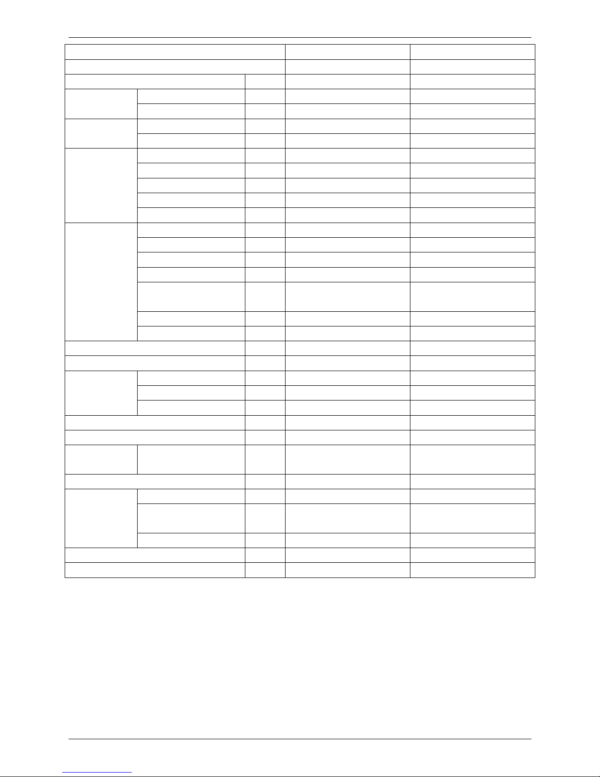
12. The Specification of Power
Type MCC-24HRN1 MCC-30HRN1 MCC-30HRN1-R
Power
Phase 1-phase 1-phase 3-phase
Frequency and
Voltage
220-240V, 50Hz 220-240V, 50Hz 380-415V, 50Hz
Circuit Breaker/ Fuse (A) 40/25 40/25 25/15
Indoor Unit Power Wiring (mm2) 3×4.0 3×4.0 5×2.5
Indoor/Outdoor Connecting
Wiring (mm2)
Ground Wiring 4.0 4.0 2.5
Outdoor Unit Power
Wiring
3×4.0 3×4.0 5×2.5
Strong Electric
Signal
3×2.5 3×2.5 3×1.0
Weak Electric Signal
1-core shield wire
1×0.5
1-core shield wire
1×0.5
Type MCC-36HRN1 MCC-36HRN1-R MCC-48HRN1-R
Power
Phase 1-phase 3-phase 3-phase
Frequency and Voltage
220-240V, 50Hz 380-415V, 50Hz 380-415V, 50Hz
Circuit Breaker/ Fuse (A) 40/25 25/15 25/15
Indoor Unit Power Wiring (mm2) 3×4.0 5×2.5 5×2.5
Indoor/Outdoor Connecting Wiring
(mm2)
4.0 4.0 2.5 2.5
Outdoor Unit Power
Wiring
3×4.0 5×2.5 5×2.5
Strong Electric Signal 3×2.5 3×1.0 3×1.0
Weak Electric Signal
1-core shield wire
1×0.5
Page 54
Field Wiring MCAC-UTSM-2008-11
52 Indoor Units
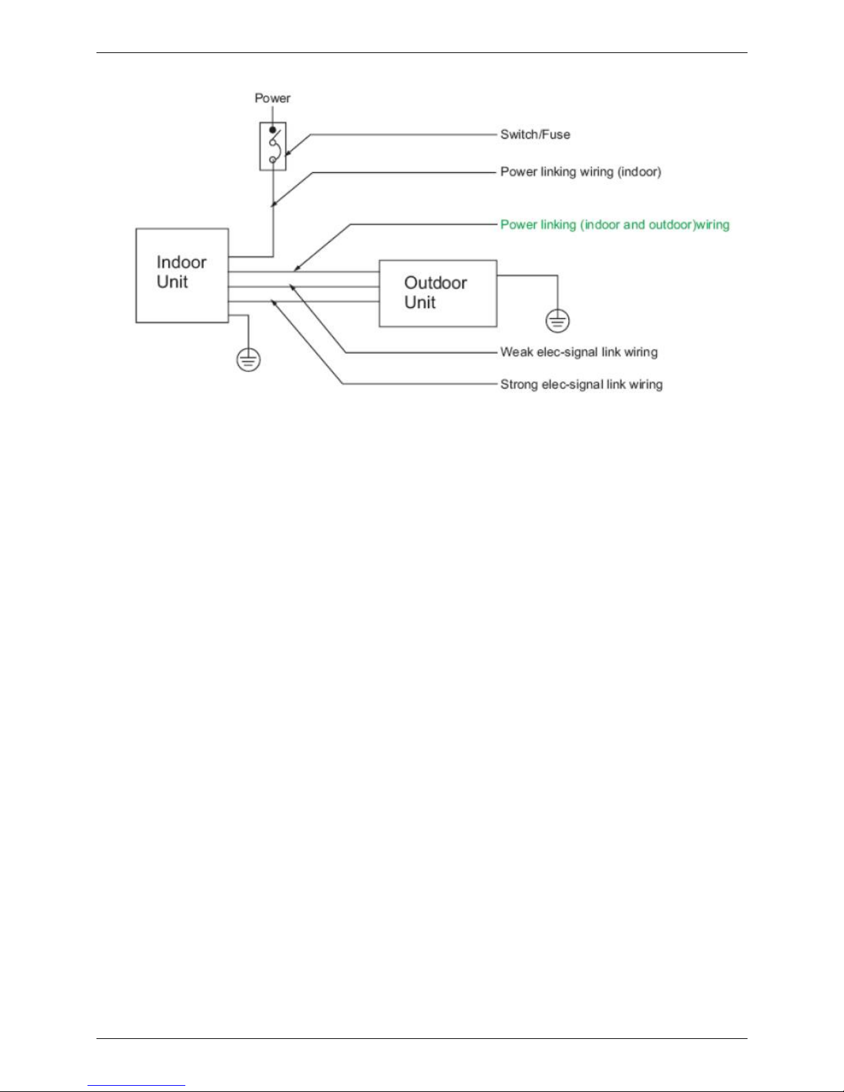
13. Field Wiring
Page 55

MCAC-UTSM-2008-11 Ceiling & Floor Type
Indoor Units 53
Ceiling & Floor Type
1. Features .................................................................................................... 54
2. Specifications .......................................................................................... 55
3. Dimensions .............................................................................................. 59
4. Service Space........................................................................................... 60
5. Wiring Diagrams ...................................................................................... 61
6. Air Velocity and Temperature Distributions........................................... 65
7. Capacity Tables ........................................................................................ 67
8. Electric Characteristics ........................................................................... 76
9. Sound Levels ........................................................................................... 76
10. Exploded View ....................................................................................... 77
11. Accessories ............................................................................................ 84
12. The Specification of Power ................................................................... 84
13. Field Wiring ............................................................................................ 85
Page 56

Features MCAC-UTSM-2008-11
54 Indoor Units
1. Features
1.1. New design, more modern and elegant appearance.
1.2. Convenient installation
--The ceiling type can be easily installed into a corner of the ceiling even if the ceiling is very narrow
--It is especially useful when installation of an air conditioner in the center of the ceiling is impossible
due to a structure such as one lighting
1.3. Two direction auto swing (vertical & horizontal) and wide angle air flow
--Air flow directional control minimizes the air resistance and produces wilder air flow to vertical
direction.
--The range of horizontal air discharge is widened which secures wider air flow distribution to provide
more comfortable air circulation no matter where the unit is set up
1.4. Three level fan speed, more humanism design, meets different air-supply requirement.
1.5. Water proof by utilizing the absorbing plastic film on water collector.
1.6. Easy operation. Auto-restart function, remote control and optional wire control method.
1.7. Low noise level plus compact size
--Shape of the blades has been improved to prevent noise caused by turbulence.
Page 57

MCAC-UTSM-2008-11 Specifications
Indoor Units 55
2. Specifications
Model
MUB-12HRN1 MUB-18HRN1
Code 220042101900 220042101920
Power supply V-ph-Hz
220~240-1-50 220~240-1-50
Cooling
Capacity kW 3.2 5.3
Input W 1200 1900
Heating
Capacity kW 4 6
Input W 1130 1850
Indoor fan motor
Model YSK25-6L YSK55-4L
Brand Welling Welling
Input W 33.4/31.1/29.5 125/105/85
Capacitor uF 1.2uF/450V 2.5uF/450V
Speed(Hi/Mi/Lo) r/min 756/666/592 1310/1190/1040
Indoor coil
Number of rows 2 3
Tube pitch(a)×row pitch(b) mm 25.4×22 25.4×22
Fin spacing mm 1.8 1.8
Fin type (code) Hydrophilic aluminum Hydrophilic aluminium
Tube outside dia.and type mm
φ9.53 Inner grooved copper
tube
φ9.53 Inner grooved copper
tube
Coil length×height×width mm 804×254×44 828×254×66
Number of circuits 3 3
Indoor air flow(Hi/Mi/Lo) m3/h 600/480/400 878/792/700
Indoor noise level (sound pressure) dB(A) 43/41/38 43/41/38
Indoor unit
Dimension (W×H×D) mm 990×660×203 990×660×203
Packing (W×H×D) mm 1089×744×296 1089×744×296
Net/Gross weight kg 27/33 27/33
Refrigerant type R410A R410A
Design pressure MPa 4.4/2.6 4.4/2.6
Refrigerant
piping
Liquid side/Gas side mm φ6.4/φ12.7 φ6.4/φ12.7
Drainage water pipe diameter mm ODφ25 ODφ25
Connection
wiring
Power wiring mm2 3×2.5 3×2.5
Strong electric signal
wiring
mm2 5×2.5 5×2.5
Weak electric signal wiring mm2 1-core shield wire 1×0.5 1-core shield wire 1×0.5
Controller R05/BGE(standard) R05/BGE(standard)
Operation temperature ℃ 17-30 17-30
Notes: 1. Nominal cooling capacities are based on the following conditions:
Indoor temp: 27°CDB, 19°CWB; Outdoor temp: 35°CDB;
2. Nominal heating capacities are based on the following conditions:
Indoor temp: 20°CDB; Outdoor temp: 7°CDB, 6°CWB;
3. Actual noise level may differ, depending on the room structure, etc, since these noise values are from an anechoic
room.
Page 58
Specifications MCAC-UTSM-2008-11
56 Indoor Units
Model
MUB-24HRN1 MUB-30HRN1
Code 220042101940 220044300050
Power supply V-ph-Hz
220~240-1-50 220~240-1-50
Cooling
Capacity kW 7.1 9
Input W 2700 3750
Heating
Capacity kW 7.6 9.5
Input W 2800 3500
Indoor fan motor
Model YSK55-4L YSK80-4A
Brand Welling Welling
Input W 125/105/85 143/122/110
Capacitor uF 2.5uF/450V 3.5uF/450V
Speed(Hi/Mi/Lo) r/min 1310/1190/1040 1310/1210/1115
Indoor coil
Number of rows 3 3
Tube pitch(a)×row pitch(b) mm 25.4×22 25.4×22
Fin spacing mm 1.8 1.8
Fin type (code) Hydrophilic aluminium Hydrophilic aluminum
Tube outside dia.and type mm
φ9.53 Inner grooved copper
tube
φ9.53 Inner grooved copper
tube
Coil length×height×width mm 828×254×66 1094×254×66
Number of circuits 3 5
Indoor air flow(Hi/Mi/Lo) m3/h 1200/900/700 1400/1200/1000
Indoor noise level (sound pressure) dB(A) 45/43/40 45/43/40
Indoor unit
Dimension (W×H×D) mm 990×660×203 1280×660×203
Packing (W×H×D) mm 1089×744×296 1379×744×296
Net/Gross weight kg 27/33 35/40
Refrigerant type R410A R410A
Design pressure MPa 4.4/2.6 4.4/2.6
Refrigerant
piping
Liquid side/Gas side mm φ9.5/φ15.9 φ12.7/φ19
Drainage water pipe diameter mm ODφ25 ODφ25
Connection
wiring
Power wiring mm2 3×2.5 3×2.5
Strong electric signal
wiring
mm2 3×2.5 3×2.5
Weak electric signal wiring mm2 1-core shield wire 1×0.5 1-core shield wire 1×0.5
Controller R05/BGE(standard) R05/BGE(standard)
Operation temperature
℃
17-30 17-30
Notes: 1. Nominal cooling capacities are based on the following conditions:
Indoor temp: 27°CDB, 19°CWB; Outdoor temp: 35°CDB;
2. Nominal heating capacities are based on the following conditions:
Indoor temp: 20°CDB; Outdoor temp: 7°CDB, 6°CWB;
3. Actual noise level may differ, depending on the room structure, etc, since these noise values are from an anechoic
room.
Page 59

MCAC-UTSM-2008-11 Specifications
Indoor Units 57
Model
MUB-30HRN1 MUB-36HRN1
Code 220042102000 220044400160
Power supply V-ph-Hz
380~415-3-50 220~240-1-50
Cooling
Capacity kW 9 10.5
Input W 3750 3750
Heating
Capacity kW 9.5 12
Input W 3500 3500
Indoor fan motor
Model YSK80-4A YSK80-4A
Brand Welling Welling
Input W 143/122/110 143/122/110
Capacitor uF 3.5uF/450V 3.5uF/450V
Speed(Hi/Mi/Lo) r/min 1310/1210/1115 1310/1210/1115
Indoor coil
Number of rows 3 3
Tube pitch(a)×row pitch(b) mm 25.4×22 25.4×22
Fin spacing mm 1.8 1.8
Fin type (code) Hydrophilic aluminum Hydrophilic aluminum
Tube outside dia.and type mm
φ9.53 Inner grooved copper
tube
φ9.53 Inner grooved copper
tube
Coil length×height×width mm 1094×254×66 1094×254×66
Number of circuits 5 5
Indoor air flow(Hi/Mi/Lo) m3/h 1400/1200/1000 1400/1200/1000
Indoor noise level (sound pressure) dB(A) 45/43/40 45/43/40
Indoor unit
Dimension (W×H×D) mm 1280×660×203 1280×660×203
Packing (W×H×D) mm 1379×744×296 1379×744×296
Net/Gross weight kg 35/40 35/40
Refrigerant type R410A R410A
Design pressure MPa 4.4/2.6 4.4/2.6
Refrigerant
piping
Liquid side/Gas side mm φ12.7/φ19 φ12.7/φ19
Drainage water pipe diameter mm ODφ25 ODφ25
Connection
wiring
Power wiring mm2 5×2.5 3×2.5
Strong electric signal
wiring
mm2 3×2.5 3×2.5
Weak electric signal wiring mm2 — 1-core shield wire 1×0.5
Controller R05/BGE(standard) R05/BGE(standard)
Operation temperature
℃
17-30 17-30
Notes: 1. Nominal cooling capacities are based on the following conditions:
Indoor temp: 27°CDB, 19°CWB; Outdoor temp: 35°CDB;
2. Nominal heating capacities are based on the following conditions:
Indoor temp: 20°CDB; Outdoor temp: 7°CDB, 6°CWB;
3. Actual noise level may differ, depending on the room structure, etc, since these noise values are from an anechoic
room.
Page 60

Specifications MCAC-UTSM-2008-11
58 Indoor Units
Model
MUB-36HRN1 MUB-48HRN1-R MUB-60HRN1-R
Code 220042102020 220042102040 220042102060
Power supply V-ph-Hz
380~415-3-50 380~415-3-50 380~415-3-50
Cooling
Capacity kW 10.5 14 16
Input W 3750 4700 5578
Heating
Capacity kW 12 15 19
Input W 3700 4731 5764
Indoor fan
motor
Model YSK80-4A YSK59-4D(×2) YSK59-4D(×2)
Brand Welling Welling Welling
Input W 143/122/110 89.5/81.5/77.5 89.5/81.5/77.5
Capacitor uF 3.5uF/450V 2.5uF/450V 2.5uF/450V
Speed(Hi/Mi/Lo) r/min 1310/1210/1115 1170/1070/995 1170/1070/995
Indoor coil
Number of rows 3 3 3
Tube pitch(a)×row
pitch(b)
mm 25.4×22 25.4×22 25.4×22
Fin spacing mm 1.8 1.8 1.8
Fin type (code) Hydrophilic aluminum Hydrophilic aluminium Hydrophilic aluminium
Tube outside dia.and
type
mm
φ9.53 Inner grooved
copper tube
φ9.53 Inner grooved
copper tube
φ9.53 Inner grooved
copper tube
Coil
length×height×width
mm 1094×254×66 1384×254×66 1384×254×66
Number of circuits 5 5 5
Indoor air flow(Hi/Mi/Lo) m3/h 1400/1200/1000 2136/1985/1775 2343/2085/1736
Indoor noise level (sound pressure) dB(A) 45/43/40 47/45/42 49/47/44
Indoor unit
Dimension (W×H×D) mm 1280×660×203 1670×680×240 1670×680×240
Packing (W×H×D) mm 1379×744×296 1764×760×329 1764×760×329
Net/Gross weight kg 35/40 52/59 52/59
Refrigerant type R410A R410A R410A
Design pressure MPa 4.4/2.6 4.4/2.6 4.4/2.6
Refrigerant
piping
Liquid side/Gas side mm φ12.7/φ19 φ12.7/φ19 φ12.7/φ19
Drainage water pipe diameter mm ODφ25 ODφ25 ODφ25
Connection
wiring
Power wiring mm2 5×2.5 5×2.5 5×2.5
Strong electric signal
wiring
mm2 3×2.5 3×2.5 3×2.5
Weak electric signal
wiring
mm2 — — —
Controller R05/BGE(standard) R05/BGE(standard) R05/BGE(standard)
Operation temperature ℃ 17-30 17-30 17-30
Notes: 1. Nominal cooling capacities are based on the following conditions:
Indoor temp: 27°CDB, 19°CWB; Outdoor temp: 35°CDB;
2. Nominal heating capacities are based on the following conditions:
Indoor temp: 20°CDB; Outdoor temp: 7°CDB, 6°CWB;
3. Actual noise level may differ, depending on the room structure, etc, since these noise values are from an anechoic
room.
Page 61

MCAC-UTSM-2008-11 Dimensions
Indoor Units 59
3. Dimensions
a. Wall mounting installation
b. Ceiling installation
Capacity (Btu/h) A B C D E F G
12000-24000 990 660 203 505 506 907 200
30000-36000 1280 660 203 795 506 1195 200
48000-60000 1670 680 240 1070 450 1542 200
Note: The dimension of 12000Btu/h, 18000Btu/h and 24000Btu/h are the same.
The dimension of 30000Btu/h and 36000Btu/h are the same.
The dimension of 48000Btu/h and 60000Btu/h are the same.
Page 62

Service Space MCAC-UTSM-2008-11
60 Indoor Units
4. Service Space
Page 63

MCAC-UTSM-2008-11 Wiring Diagrams
Indoor Units 61
5. Wiring Diagrams
5.1 MUB-12HRN1 MUB-18HRN1
Page 64

Wiring Diagrams MCAC-UTSM-2008-11
62 Indoor Units
5.2 MUB-24HRN1 MUB-30HRN1(1 phase) MUB-36HRN1(1 phase)
Page 65

MCAC-UTSM-2008-11 Wiring Diagrams
Indoor Units 63
5.3 MUB-30HRN1(3 phase) MUB-36HRN1(3 phase)
Page 66

Wiring Diagrams MCAC-UTSM-2008-11
64 Indoor Units
5.3 MUB-48HRN1-R MUB-60HRN1-R
Page 67

MCAC-UTSM-2008-11 Air Velocity and Temperature Distributions
Indoor Units 65
6. Air Velocity and Temperature Distributions
Discharge angle 60° (CEILING)
Airflow velocity
Temperature
Page 68
Air Velocity and Temperature Distributions MCAC-UTSM-2008-11
66 Indoor Units
Discharge angle 60°(FLOOR)
Temperature
Airflow velocity
Page 69

MCAC-UTSM-2008-11 Capacity Tables
Indoor Units 67
7. Capacity Tables
MUB-12HRN1
Cooling
Cooling Outdoor conditions (DB)
Indoor Conditions (kW) 21ºC 28ºC 35ºC 43ºC
21/15ºC DB/WB
TC 3.30 3.14 2.98 2.85
SC 2.44 2.41 2.38 2.39
Input 1.00 1.08 1.13 1.16
24/17ºC DB/WB
TC 3.39 3.23 3.07 2.88
SC 2.54 2.52 2.49 2.42
Input 1.06 1.13 1.18 1.24
27/19ºC DB/WB
TC 3.46 3.30
3.20
2.98
SC 2.56 2.54 2.50 2.44
Input 1.08 1.14
1.20
1.26
32/23ºC DB/WB
TC 3.52 3.39 3.33 3.07
SC 2.99 2.95 2.93 2.86
Input 1.13 1.18 1.26 1.31
Heating
Heating Outdoor conditions
Indoor Conditions (DB) (kW) 24/18ºC DB/WB 7/6ºC DB/WB 2/1ºC DB/WB -5/-6ºC DB/WB
15ºC
TC 5.20 4.20 3.44 3.12
Input 1.22 1.05 0.90 0.85
20ºC
TC 5.04 4.00 3.24 3.04
Input 1.33 1.13 0.99 0.92
27ºC
TC 4.72 3.76 3.04 2.96
Input 1.41 1.22 1.07 0.99
Remark:
TC : Total capacity ; kW
SC: Sensible heat capacity ; kW
Input: Input power ; kW
Page 70

Capacity Tables MCAC-UTSM-2008-11
68 Indoor Units
MUB-18HRN1
Cooling
Cooling Outdoor conditions (DB)
Indoor Conditions (kW) 21ºC 28ºC 35ºC 43ºC
21/15ºC DB/WB
TC 5.46 5.19 4.93 4.72
SC 4.04 4.00 3.94 3.96
Input 1.58 1.71 1.79 1.84
24/17ºC DB/WB
TC 5.62 5.35 5.09 4.77
SC 4.21 4.18 4.12 4.01
Input 1.67 1.79 1.86 1.96
27/19ºC DB/WB
TC 5.72 5.46 5.30 4.93
SC 4.24 4.20 4.13 4.04
Input 1.71 1.81 1.90 2.00
32/23ºC DB/WB
TC 5.83 5.62 5.51 5.09
SC 4.96 4.89 4.85 4.73
Input 1.79 1.86 2.00 2.07
Heating
Heating Outdoor conditions
Indoor Conditions (DB) (kW) 24/18ºC DB/WB 7/6ºC DB/WB 2/1ºC DB/WB -5/-6ºC DB/WB
15ºC
TC 7.80 6.30 5.16 4.68
Input 2.00 1.72 1.48 1.39
20ºC
TC 7.56 6.00 4.86 4.56
Input 2.18 1.85 1.63 1.50
27ºC
TC 7.08 5.64 4.56 4.44
Input 2.31 2.00 1.76 1.63
Remark:
TC : Total capacity ; kW
SC: Sensible heat capacity ; kW
Input: Input power ; kW
Page 71

MCAC-UTSM-2008-11 Capacity Tables
Indoor Units 69
MUB-24HRN1
Cooling
Cooling Outdoor conditions (DB)
Indoor Conditions (kW) 21ºC 28ºC 35ºC 43ºC
21/15ºC DB/WB
TC 7.31 6.96 6.60 6.32
SC 5.41 5.36 5.28 5.31
Input 2.24 2.43 2.54 2.62
24/17ºC DB/WB
TC 7.53 7.17 6.82 6.39
SC 5.64 5.59 5.52 5.37
Input 2.38 2.54 2.65 2.78
27/19ºC DB/WB
TC 7.67 7.31 7.10 6.60
SC 5.67 5.63 5.54 5.41
Input 2.43 2.57 2.70 2.84
32/23ºC DB/WB
TC 7.81 7.53 7.38 6.82
SC 6.64 6.55 6.50 6.34
Input 2.54 2.65 2.84 2.94
Heating
Heating Outdoor conditions
Indoor Conditions (DB) (kW) 24/18ºC DB/WB 7/6ºC DB/WB 2/1ºC DB/WB -5/-6ºC DB/WB
15ºC
TC 9.88 7.98 6.54 5.93
Input 3.02 2.60 2.24 2.10
20ºC
TC 9.58 7.60 6.16 5.78
Input 3.30 2.80 2.46 2.27
27ºC
TC 8.97 7.14 5.78 5.62
Input 3.50 3.02 2.66 2.46
Remark:
TC : Total capacity ; kW
SC: Sensible heat capacity ; kW
Input: Input power ; kW
Page 72

Capacity Tables MCAC-UTSM-2008-11
70 Indoor Units
MUB-30HRN1 (1 phase)
Cooling
Cooling Outdoor conditions (DB)
Indoor Conditions (kW) 21ºC 28ºC 35ºC 43ºC
21/15ºC DB/WB
TC 9.27 8.82 8.37 8.01
SC 6.86 6.79 6.70 6.73
Input 3.11 3.38 3.53 3.64
24/17ºC DB/WB
TC 9.54 9.09 8.64 8.10
SC 7.16 7.09 7.00 6.80
Input 3.30 3.53 3.68 3.86
27/19ºC DB/WB
TC 9.72 9.27
9.00
8.37
SC 7.19 7.14 7.02 6.86
Input 3.38 3.56
3.75
3.94
32/23ºC DB/WB
TC 9.90 9.54 9.36 8.64
SC 8.42 8.30 8.24 8.04
Input 3.53 3.68 3.94 4.09
Heating
Heating Outdoor conditions
Indoor Conditions (DB) (kW) 24/18ºC DB/WB 7/6ºC DB/WB 2/1ºC DB/WB -5/-6ºC DB/WB
15ºC
TC 12.35 9.98 8.17 7.41
Input 3.78 3.26 2.80 2.63
20ºC
TC 11.97 9.50 7.70 7.22
Input 4.13 3.50 3.08 2.84
27ºC
TC 11.21 8.93 7.22 7.03
Input 4.38 3.78 3.33 3.08
Remark:
TC : Total capacity ; kW
SC: Sensible heat capacity ; kW
Input: Input power ; kW
Page 73

MCAC-UTSM-2008-11 Capacity Tables
Indoor Units 71
MUB-30HRN1 (3 phase)
Cooling
Cooling Outdoor conditions (DB)
Indoor Conditions (kW) 21ºC 28ºC 35ºC 43ºC
21/15ºC DB/WB
TC 9.27 8.82 8.37 8.01
SC 6.86 6.79 6.70 6.73
Input 3.11 3.38 3.53 3.64
24/17ºC DB/WB
TC 9.54 9.09 8.64 8.10
SC 7.16 7.09 7.00 6.80
Input 3.30 3.53 3.68 3.86
27/19ºC DB/WB
TC 9.72 9.27
9.00
8.37
SC 7.19 7.14 7.02 6.86
Input 3.38 3.56
3.75
3.94
32/23ºC DB/WB
TC 9.90 9.54 9.36 8.64
SC 8.42 8.30 8.24 8.04
Input 3.53 3.68 3.94 4.09
Heating
Heating Outdoor conditions
Indoor Conditions (DB) (kW) 24/18ºC DB/WB 7/6ºC DB/WB 2/1ºC DB/WB -5/-6ºC DB/WB
15ºC
TC 12.35 9.98 8.17 7.41
Input 3.78 3.26 2.80 2.63
20ºC
TC 11.97 9.50 7.70 7.22
Input 4.13 3.50 3.08 2.84
27ºC
TC 11.21 8.93 7.22 7.03
Input 4.38 3.78 3.33 3.08
Remark:
TC : Total capacity ; kW
SC: Sensible heat capacity ; kW
Input: Input power ; kW
Page 74

Capacity Tables MCAC-UTSM-2008-11
72 Indoor Units
MUB-36HRN1 (1 phase)
Cooling
Cooling Outdoor conditions (DB)
Indoor Conditions (kW) 21ºC 28ºC 35ºC 43ºC
21/15ºC DB/WB
TC 10.82 10.29 9.77 9.35
SC 8.00 7.92 7.81 7.85
Input 3.11 3.38 3.53 3.64
24/17ºC DB/WB
TC 11.13 10.61 10.08 9.45
SC 8.35 8.27 8.16 7.94
Input 3.30 3.53 3.68 3.86
27/19ºC DB/WB
TC 11.34 10.82
10.50
9.77
SC 8.39 8.33 8.19 8.01
Input 3.38 3.56
3.75
3.94
32/23ºC DB/WB
TC 11.55 11.13 10.92 10.08
SC 9.82 9.68 9.61 9.37
Input 3.53 3.68 3.94 4.09
Heating
Heating Outdoor conditions
Indoor Conditions (DB) (kW) 24/18ºC DB/WB 7/6ºC DB/WB 2/1ºC DB/WB -5/-6ºC DB/WB
15ºC
TC 15.60 12.60 10.32 9.36
Input 3.78 3.26 2.80 2.63
20ºC
TC 15.12 12.00 9.72 9.12
Input 4.13 3.50 3.08 2.84
27ºC
TC 14.16 11.28 9.12 8.88
Input 4.38 3.78 3.33 3.08
Remark:
TC : Total capacity ; kW
SC: Sensible heat capacity ; kW
Input: Input power ; kW
Page 75

MCAC-UTSM-2008-11 Capacity Tables
Indoor Units 73
MUB-36HRN1 (3 phase)
Cooling
Cooling Outdoor conditions (DB)
Indoor Conditions (kW) 21ºC 28ºC 35ºC 43ºC
21/15ºC DB/WB
TC 10.82 10.29 9.77 9.35
SC 8.00 7.92 7.81 7.85
Input 3.11 3.38 3.53 3.64
24/17ºC DB/WB
TC 11.13 10.61 10.08 9.45
SC 8.35 8.27 8.16 7.94
Input 3.30 3.53 3.68 3.86
27/19ºC DB/WB
TC 11.34 10.82
10.50
9.77
SC 8.39 8.33 8.19 8.01
Input 3.38 3.56
3.75
3.94
32/23ºC DB/WB
TC 11.55 11.13 10.92 10.08
SC 9.82 9.68 9.61 9.37
Input 3.53 3.68 3.94 4.09
Heating
Heating Outdoor conditions
Indoor Conditions (DB) (kW) 24/18ºC DB/WB 7/6ºC DB/WB 2/1ºC DB/WB -5/-6ºC DB/WB
15ºC
TC 15.60 12.60 10.32 9.36
Input 4.00 3.44 2.96 2.78
20ºC
TC 15.12 12.00 9.72 9.12
Input 4.37 3.70 3.26 3.00
27ºC
TC 14.16 11.28 9.12 8.88
Input 4.63 4.00 3.52 3.26
Remark:
TC : Total capacity ; kW
SC: Sensible heat capacity ; kW
Input: Input power ; kW
Page 76

Capacity Tables MCAC-UTSM-2008-11
74 Indoor Units
MUB-48HRN1-R
Cooling
Cooling Outdoor conditions (DB)
Indoor Conditions (kW) 21ºC 28ºC 35ºC 43ºC
21/15ºC DB/WB
TC 14.42 13.72 13.02 12.46
SC 10.67 10.56 10.42 10.47
Input 3.90 4.23 4.42 4.56
24/17ºC DB/WB
TC 14.84 14.14 13.44 12.60
SC 11.13 11.03 10.89 10.58
Input 4.14 4.42 4.61 4.84
27/19ºC DB/WB
TC 15.12 14.42 14.00 13.02
SC 11.19 11.10 10.92 10.68
Input 4.23 4.47 4.70 4.94
32/23ºC DB/WB
TC 15.40 14.84 14.56 13.44
SC 13.09 12.91 12.81 12.50
Input 4.42 4.61 4.94 5.12
Heating
Heating Outdoor conditions
Indoor Conditions (DB) (kW) 24/18ºC DB/WB 7/6ºC DB/WB 2/1ºC DB/WB -5/-6ºC DB/WB
15ºC
TC 19.50 15.75 12.90 11.70
Input 5.11 4.40 3.78 3.55
20ºC
TC 18.90 15.00 12.15 11.40
Input 5.58 4.731 4.16 3.83
27ºC
TC 17.70 14.10 11.40 11.10
Input 5.91 5.11 4.49 4.16
Remark:
TC : Total capacity ; kW
SC: Sensible heat capacity ; kW
Input: Input power ; kW
Page 77

MCAC-UTSM-2008-11 Capacity Tables
Indoor Units 75
MUB-60HRN1-R
Cooling
Cooling Outdoor conditions (DB)
Indoor Conditions (kW) 21ºC 28ºC 35ºC 43ºC
21/15ºC DB/WB
TC 16.48 15.68 14.88 14.24
SC 12.20 12.07 11.90 11.96
Input 4.63 5.02 5.24 5.41
24/17ºC DB/WB
TC 16.96 16.16 15.36 14.40
SC 12.72 12.60 12.44 12.10
Input 4.91 5.24 5.47 5.75
27/19ºC DB/WB
TC 17.28 16.48 16.00 14.88
SC 12.79 12.69 12.48 12.20
Input 5.02 5.30 5.578 5.86
32/23ºC DB/WB
TC 17.60 16.96 16.64 15.36
SC 14.96 14.76 14.64 14.28
Input 5.24 5.47 5.86 6.08
Heating
Heating Outdoor conditions
Indoor Conditions (DB) (kW) 24/18ºC DB/WB 7/6ºC DB/WB 2/1ºC DB/WB -5/-6ºC DB/WB
15ºC
TC 24.70 19.95 16.34 14.82
Input 6.23 5.36 4.61 4.32
20ºC
TC 23.94 19.00 15.39 14.44
Input 6.80 5.764 5.07 4.67
27ºC
TC 22.42 17.86 14.44 14.06
Input 7.21 6.23 5.48 5.07
Remark:
TC : Total capacity ; kW
SC: Sensible heat capacity ; kW
Input: Input power ; kW
Page 78

Electric Characteristics MCAC-UTSM-2008-11
76 Indoor Units
8. Electric Characteristics
Model
Indoor Units Power Supply Indoor Fan Motor
Hz Voltage
Min. Max. MCA MFA kW FLA
MUB-12HRN1 50 220-240V 198V 254V 0.2 16 0.025 0.145
MUB-18HRN1 50 220-240V 198V 254V 0.71 16 0.055 0.57
MUB-24HRN1 50 220-240V 198V 254V 0.71 25 0.055 0.57
MUB-30HRN1 50 220-240V 198V 254V 0.79 25 0.08 0.63
MUB-30HRN1 50 380-415V 342V 418V 0.79 20 0.08 0.63
MUB-36HRN1 50 220-240V 198V 254V 0.79 25 0.08 0.63
MUB-36HRN1 50 380-415V 342V 418V 0.79 20 0.08 0.63
MUB-48HRN1-R 50 380-415V 342V 418V 1.25 20 0.059 0.39(×2)
MUB-60HRN1-R 50 380-415V 342V 418V 1.25 20 0.059 0.39(×2)
Remark:
MCA: Min. Current Amps. (A)
MFA: Max. Fuse Amps. (A)
KW: Fan Motor Rated Output (kW)
FLA: Full Load Amps. (A)
9. Sound Levels
Ceiling Floor
Model
Noise level
H M L
MUB-12HRN1 43 41 38
MUB-18HRN1 43 41 38
MUB-24HRN1 45 43 40
MUB-30HRN1 (1 phase) 45 43 40
MUB-30HRN1 (3 phase) 45 43 40
MUB-36HRN1 (1 phase) 45 43 40
MUB-36HRN1 (3 phase) 45 43 40
MUB-48HRN1-R 47 45 42
MUB-60HRN1-R 49 47 44
Page 79

MCAC-UTSM-2008-11 Exploded View
Indoor Units 77
10. Exploded View
10.1 MUB-12HRN1
No. Part Name Quantity No. Part Name Quantity
1 Filter 2 20 Evaporator ass'y 1
2 Grille clamp 2 21 Installation board 1
3 Grille 1 22 Foam ass'y 1
4 Grille clamp 2 23 Foam ass'y 1
5 Grille strengthening rib 1 24 Evaporator Left support 1
6 Volute shell 2 25 Foam ass'y 1
7 Grille lock 1 26 Support board 1
8 Plastic fan 2 27 Evaporator right clapboard 1
9 Motor clamp 1 28 Evaporator left clapboard 1
10 Motor clamp 1 29 Cover 1
11 Volute shell 2 30 Display panel box 1
12 Board 1 31 Display board ass'y 1
13 Middle beam 1 32 Manual button 1
14 E-part box cover 1 33 Air outlet ass'y 1
15 E-part box ass'y 1 34 Foam 1
15.1 Main controller ass'y 1 35 Drainage pan holder 1
15.2 Motor capacitor 1 36 Drainage pan ass'y 1
15.3 Wire joint 1 37 Plastic cover 2
15.4 Wire joint 1 38 Motor 1
15.5 Transformer 1 39 Panel ass'y 1
16 Left cover 1 40 Remote controller 1
17 Installation board 1 41 Installation bracket 1
18 Base ass'y 1 42 Room temp sensor ass'y 1
19 Rear cover 1 43 Temp.sensor ass'y 1
Page 80
Exploded View MCAC-UTSM-2008-11
78 Indoor Units
10.2 MUB-18HRN1
No. Part Name Quantity No. Part Name Quantity
1 Filter 2 20 Evaporator ass'y 1
2 Grille clamp 2 21 Installation board 1
3 Grille 1 22 Foam ass'y 1
4 Grille hang 2 23 Foam ass'y 1
5 Grille strengthening rib 1 24 Evaporator Left support 1
6 Volute shell 2 25 Foam ass'y 1
7 Grille lock 1 26 Support board 1
8 Plastic fan 2 27 Evaporator right clapboard 1
9 Motor clamp 1 28 Evaporator left clapboard 1
10 Motor clamp 1 29 Cover 1
11 Volute shell 2 30 Display panel box 1
12 Board 1 31 Display board ass'y 1
13 Middle beam 1 32 Manual button 1
14 E-part box cover 1 33 Air outlet frame mount ass'y 1
15 E-part box ass'y 1 34 Foam 1
15.1 Main controller ass'y 1 35 Drainage pan holder 1
15.2 Motor capacitor 1 36 Drainage pan ass'y 1
15.3 Wire joint 1 37 Plastic cover 2
15.4 Wire joint 1 38 Motor 1
15.5 Transformer 1 39 Panel ass'y 1
16 Left cover 1 40 Remote controller 1
17 Installation board 1 41 Installation bracket 1
18 Base ass'y 1 42 Room temp. sensor ass'y 1
19 Rear cover 1 43 Evaporator temp. sensor ass'y 1
Page 81

MCAC-UTSM-2008-11 Exploded View
Indoor Units 79
10.3 MUB-24HRN1
No. Part Name Quantity No. Part Name Quantity
1 Filter 2 20 Evaporator ass'y 1
2 Grille clamp 2 21 Installation board 1
3 Grille 1 22 Foam ass'y 1
4 Grille hang 2 23 Foam ass'y 1
5 Grille strengthening rib 1 24 Evaporator Left support 1
6 Volute shell 2 25 Foam ass'y 1
7 Grille lock 1 26 Support board 1
8 Plastic fan 2 27 Evaporator right clapboard 1
9 Motor clamp 1 28 Evaporator left clapboard 1
10 Motor clamp 1 29 Cover 1
11 Volute shell 2 30 Display panel box 1
12 Board 1 31 Display board ass'y 1
13 Middle beam 1 32 Manual button 1
14 E-part box cover 1 33 Air outlet frame mount ass'y 1
15 E-part box ass'y 1 34 Foam 1
15.1 Main controller ass'y 1 35 Drainage pan holder 1
15.2 Motor capacitor 1 36 Drainage pan ass'y 1
15.3 Wire joint 1 37 Plastic cover 2
15.4 Wire joint 1 38 Motor 1
15.5 Transformer 1 39 Panel ass'y 1
16 Left cover 1 40 Remote controller 1
17 Installation board 1 41 Installation bracket 1
18 Base ass'y 1 42 Room temp. sensor ass'y 1
19 Rear cover 1 43 Evaporator temp. sensor ass'y 1
Page 82

Exploded View MCAC-UTSM-2008-11
80 Indoor Units
10.4 MUB-30HRN1 MUB-36HRN1(1 phase)
No. Part Name Quantity No. Part Name Quantity
1 Filter 3 20 Evaporator ass'y 1
2 Grille clamp 2 21 Installation board 1
3 Grille 1 22 Foam ass'y 1
4 Grille clamp 2 23 Foam ass'y 1
5 Grille strengthening rib 1 24 Evaporator Left support 1
6 Volute shell 3 25 Foam ass'y 1
7 Grille lock 2 26 Support board 1
8 Plastic fan 3 27 Evaporator right clapboard 1
9 Motor clamp 1 28 Evaporator left clapboard 1
10 Motor clamp 1 29 Cover 1
11 Volute shell 3 30 Display panel box 1
12 Board 1 31 Display board ass'y 1
13 Middle beam 1 32 Manual button 1
14 E-part box cover 1 33 Air outlet ass'y 1
15 E-part box ass'y 1 34 Foam 1
15.1 Main controller ass'y 1 35 Drainage pan holder 1
15.2 Motor capacitor 1 36 Drainage pan ass'y 1
15.3 Wire joint 1 37 Plastic cover 1
15.4 Wire joint 1 38 Motor 1
15.5 Transformer 1 39 Panel ass'y 1
16 Left cover 1 40 Remote controller 1
17 Installation board 1 41 Installation bracket 1
18 Base ass'y 1 42 Room temp sensor ass'y 1
19 Rear cover 1 43 Temp.sensor ass'y 1
Page 83

MCAC-UTSM-2008-11 Exploded View
Indoor Units 81
10.5 MUB-30HRN1 MUB-36HRN1(3 phase)
No. Part Name Quantity No. Part Name Quantity
1 Filter 3 20 Evaporator ass'y 1
2 Grille clamp 2 21 Installation board 1
3 Grille 1 22 Foam ass'y 1
4 Grille clamp 2 23 Foam ass'y 1
5 Grille strengthening rib 1 24 Evaporator Left support 1
6 Volute shell 3 25 Foam ass'y 1
7 Grille lock 2 26 Support board 1
8 Plastic fan 3 27 Evaporator right clapboard 1
9 Motor clamp 1 28 Evaporator left clapboard 1
10 Motor clamp 1 29 Cover 1
11 Volute shell 3 30 Display panel box 1
12 Board 1 31 Display board ass'y 1
13 Middle beam 1 32 Manual button 1
14 E-part box cover 1 33 Air outlet ass'y 1
15 E-part box ass'y 1 34 Foam 1
15.1 Main controller ass'y 1 35 Drainage pan holder 1
15.2 Motor capacitor 1 36 Drainage pan ass'y 1
15.3 Wire joint 1 37 Plastic cover 1
15.4 Wire joint 1 38 Motor 1
15.5 Transformer 1 39 Panel ass'y 1
16 Left cover 1 40 Remote controller 1
17 Installation board 1 41 Installation bracket 1
18 Base ass'y 1 42 Room temp sensor ass'y 1
19 Rear cover 1 43 Temp.sensor ass'y 1
Page 84

Exploded View MCAC-UTSM-2008-11
82 Indoor Units
10.6 MUB-48HRN1-R
No. Part Name Quantity No. Part Name Quantity
1 Grille ass'y 2 21 Volute shell 4
2 Motor clamp 2 22 Middle beam 1
3 Motor clamp 2 23 E-part box cover 1
4 Filter bracket 2 24 E-part box ass'y 1
5 Installation board 1 24.1 Main controller ass'y 1
6 Installation board 1 24.2 Motor capacitor 2
7 Filter bracket 2 24.3 Wire joint 1
8 Right sealed board 1 24.4 Wire joint 1
9 left sealed board 1 24.5 Transformer 1
10 Pipe clamp board 1 25 Foam 2
11 Cover 1 26 Top cover ass'y 1
12 Left cover 1 27 Drainage pan ass'y 1
13 Display board ass'y 1 28 Plastic cover 1
14 Display installation box 1 29 Foam 2
15 Air outlet ass'y 1 30 Filter 4
15.1 Display board ass'y 1 31 Evaporator ass'y 1
16 Base ass'y 1 31.1 Temp. sensor ass'y 1
17 Plastic fan 4 32 Remote controller 1
18 Volute shell 4 33 Installation bracket 1
19 Motor 2 34 Room temp. sensor ass'y 1
20 Motor bracket 2
31.1
Page 85

MCAC-UTSM-2008-11 Exploded View
Indoor Units 83
10.7 MUB-60HRN1-R
No. Part Name Quantity No. Part Name Quantity
1 Grille ass'y 2 21 Volute shell 4
2 Motor clamp 2 22 Middle beam 1
3 Motor clamp 2 23 E-part box cover 1
4 Filter bracket 2 24 E-part box ass'y 1
5 Installation board 1 24.1 Main controller ass'y 1
6 Installation board 1 24.2 Motor capacitor 2
7 Filter bracket 2 24.3 Wire joint 1
8 Right sealed board 1 24.4 Wire joint 1
9 Left sealed board 1 24.5 Transformer 1
10 Pipe clamp board 1 25 Foam 2
11 Cover 1 26 Top cover ass'y 1
12 Left cover 1 27 Drainage pan ass'y 1
13 Display board ass'y 1 28 Plastic cover 1
14 Display installation box 1 29 Foam 2
15 Air outlet frame ass'y 1 30 Filter 4
15.1 Display board ass'y 1 31 Evaporator ass'y 1
16 Base ass'y 1 31.1 Temp. sensor ass'y 1
17 Plastic fan 4 32 Remote controller 1
18 Volute shell 4 33 Installation bracket 1
19 Motor 2 34 Room temp. sensor ass'y 1
20 Motor bracket 2
Page 86

Accessories MCAC-UTSM-2008-11
84 Indoor Units
11. Accessories
Installation fittings
Name Shape Quantity
1.Hook
2
2.Hanging arm
2
Remote controller & Its
Holder
3. Remote controller
1
4. Remote controller holder
1
5. Mounting screw(ST2.9×10-C-H)
2
6. Alkaline dry batteries (AM4)
2
Others
7. Owner's manual
1
8. Installation manual
1
9. Remote controller manual
1
12. The Specification of Power
Type 12000-18000Btu/h 24000-36000Btu/ h 30000-60000Btu/ h
Power
Phase 1-phase 1-phase 3-phase
Frequency and Voltage 220-240V, 50Hz 220-240V, 50Hz 380-415V, 50Hz
Circuit Breaker/ Fuse (A) 20/16 40/25 40/20
Indoor Unit Power Wiring (mm2) 3×2.5 3×2.5 5×2.5
Indoor/Outdoor
Connecting Wiring (mm2)
Ground Wiring 2.5 2.5 2.5
Outdoor Unit Power Wiring
3×2.5 5×2.5
Strong Electric Signal 5×2.5 3×2.5 3×2.5
Weak Electric Signal
1-core shield wire
1×0.5 mm2
1-core shield wire
1×0.5 mm2
Page 87

MCAC-UTSM-2008-11 Field Wiring
Indoor Units 85
13. Field Wiring
MUB-12HRN1
MUB-18HRN1
Page 88

Field Wiring MCAC-UTSM-2008-11
86 Indoor Units
MUB-24HRN1
MUB-30HRN1 MUB-36HRN1(1 phase)
Page 89

MCAC-UTSM-2008-11 Field Wiring
Indoor Units 87
MUB-30HRN1 MUB-36HRN1(3 phase)
MUB-48HRN1-R MUB-60HRN1-R
Page 90

Outdoor Units MCAC-UTSM-2008-11
88 Outdoor Units
Part 3
Outdoor Units
1. Specifications ........................................................... 89
2. Dimensions ............................................................... 94
3. Service Space ........................................................... 99
4. Piping Diagrams ..................................................... 100
5. Wiring Diagrams ..................................................... 103
6. Electric Characteristics .......................................... 109
7. Operation Limits ..................................................... 109
8. Sound Levels .......................................................... 110
9. Exploded View .........................................................111
10. Troubleshooting ................................................... 118
Page 91

MCAC-UTSM-2008-11 Specifications
Outdoor Units 89
1. Specifications
Model MOU-12HN1 MOUA-18HN1
Code 220075100110 220075200490
Power supply V-ph-Hz
220~240-1-50 220~240-1-50
Max. input consumption W 1500 2400
Max. input current A 7.0 10.9
Starting current A 26 53
Compressor
Model PA140X2C-4FT PA225X2CS-4KU1
Type ROTARY ROTARY
Brand MIDEA-TOSHIBA MIDEA-TOSHIBA
Supplier MIDEA-TOSHIBA MIDEA-TOSHIBA
Capacity Btu/h 11567 18697
Input W 1150 1855
Rated current(RLA) A 5.3 8.7
Locked rotor Amp(LRA) A 29.9 36.8
Thermal protector Internal Internal
Capacitor μF 35μF/440-450V 50μF/440V-450V
Refrigerant oil ml ESTEL OIL VG74, 480 ESTER OIL VG74, 750
Outdoor fan
motor
Model YDK24-6F YDK48-6H(A)
Type AC motor AC motor
Brand Welling Welling
Input W 58 110
Capacitor μF 2.5uF/450V 3μF/450V
Speed r/min 800 890
Outdoor coil
Number of rows 2 2
Tube pitch(a)× row
mm 21×13.37 22×19.05
Fin spacing mm 1.5 1.4
Fin type Hydrophilic aluminium Hydrophilic aluminium
Tube outside dia.and type mm
φ
7 Inner grooved copper
φ
7.94 Inner grooved copper
Coil length × height ×
mm 651×559×26.74 645×528×38.1
Number of circuits 2 5
Outdoor air flow m3/h 2100 2439
Outdoor noise level (sound pressure) dB(A) 43 48
Outdoor unit
Dimension(W×H×D) mm 838(780)×547×250 824(762)×593×282
Packing (W×H×D) mm 910×575×335 891×657×359
Net/Gross weight kg 37/39 41/44
Refrigerant
Type R410A R410A
Charged volume g 1120 1450
Design pressure MPa 4.4/2.6 4.4/2.6
Refrigerant piping
Liquid side/ Gas side mm φ6.4/φ12.7 φ6.4/φ12.7
Max. pipe length m 25 25
Max. difference in level m 15 15
Ambient temp. ℃ cooling:18~43; heating:-7~24 cooling: 18~43; heating:-7~24
Page 92

Specifications MCAC-UTSM-2008-11
90 Outdoor Units
Model MOUA-24HN1 MOU-30HN1
Code 220075300570 220075400010
Power supply V-ph-Hz
220~240-1-50 220~240-1-50
Max. input consumption W 3300 4620
Max. input current A 15 21
Starting current A 62 97
Compressor
Model PA290X3CS-4MU1 C-SBN301H5D
Type ROTARY SCROLL
Brand MIDEA-TOSHIBA SANYO
Supplier MIDEA-TOSHIBA SANYO
Capacity Btu/h 24600 33438
Input W 2430 3650
Rated current(RLA) A 11.4 17.65
Locked rotor Amp(LRA) A 61 97
Thermal protector Internal Internal
Capacitor μF 50μF/440V-450V 60uF/450V
Refrigerant oil ml ESTER OIL VG74, 950 FV68S, 1700
Outdoor fan
motor
Model YDK53-6Q YDK250-6D
Type AC motor AC motor
Brand Welling Welling
Input W 144 304
Capacitor μF 3μF/450V 10uF±5% 450V
Speed r/min 840 740
Outdoor coil
Number of rows 2 1.6
Tube pitch(a)× row
mm 22×19.05 22×19.05
Fin spacing
mm 1.4 1.6
Fin type Hydrophilic aluminium Hydrophilic aluminium
Tube outside dia.and type mm
φ7.94 Inner grooved copper
φ7.94 Inner grooved copper
Coil length × height ×
mm 820×616×38.1
727×902×38.1
Number of circuits 6 7
Outdoor air flow m3/h 3200 5000
Outdoor noise level (sound pressure) dB(A) 55 57
Outdoor unit
Dimension(W×H×D) mm 932(852)×660×340 1075(990)×966×354
Packing (W×H×D) mm 986×726×436 1120×1100×435
Net/Gross weight kg 56/61 94/104
Refrigerant
Type R410A R410A
Charged volume g 2050 3100
Design pressure MPa 4.4/2.6 4.4/2.6
Refrigerant
piping
Liquid side/ Gas side mm φ9.5/φ15.9 φ12.7/φ19
Max. pipe length m 30 30
Max. difference in level
m 15 20
Ambient temp. ℃ cooling: 18~43; heating:-7~24 cooling: 18~43; heating:-7~24
Page 93

MCAC-UTSM-2008-11 Specifications
Outdoor Units 91
Model MOU-30HN1-R MOU-36HN1
Code 220075400020 220075500670
Power supply V-ph-Hz
380~415-3-50 220~240-1-50
Max. input consumption W 4620 4620
Max. input current A 7.1 21
Starting current A 61 97
Compressor
Model C-SBN303H8D C-SBN301H5D
Type SCROLL SCROLL
Brand SANYO SANYO
Supplier SANYO(Dalian) SANYO
Capacity Btu/h 33438 33438
Input W 3650 3650
Rated current(RLA) A 6.58 17.65
Locked rotor Amp(LRA) A 61 97
Thermal protector Internal Internal
Capacitor μF / 60uF/450V
Refrigerant oil ml DAPHNE FV68S, 1700 FV68S 1700
Outdoor fan
motor
Model YDK250-6D YDK250-6D
Type AC motor AC motor
Brand Welling Welling
Input W 304 304
Capacitor μF 10uF±5% 450V 10uF±5% 450V
Speed r/min 740 740
Outdoor coil
Number of rows 1.6 1.6
Tube pitch(a)× row
mm 22×19.05 22×19.05
Fin spacing
mm 1.6 1.6
Fin type Hydrophilic aluminium Hydrophilic aluminium
Tube outside dia.and type mm
φ7.94 Inner grooved copper
φ7.94 Inner grooved copper
Coil length × height ×
mm
727×902×38.1
727×902×38.1
Number of circuits 7 7
Outdoor air flow m3/h 5000 5000
Outdoor noise level (sound pressure) dB(A) 57 57
Outdoor unit
Dimension(W×H×D) mm 1075(990)×966×354 1075(990)×966×354
Packing (W×H×D) mm 1120×1100×435 1120×1100×435
Net/Gross weight kg 99/104 99/104
Refrigerant
Type R410A R410A
Charged volume g 3100 3100
Design pressure MPa 4.4/2.6 4.4/2.6
Refrigerant
piping
Liquid side/ Gas side mm φ12.7/φ19 φ12.7/φ19
Max. pipe length m 30 30
Max. difference in level
m 20 20
Ambient temp. ℃ cooling: 18~43; heating:-7~24 cooling: 18~43; heating:-7~24
Page 94

Specifications MCAC-UTSM-2008-11
92 Outdoor Units
Model MOU-36HN1-R MOUA-48HN1-R
Code 220075500680 220075700040
Power supply V-ph-Hz
380~415-3-50 380~415-3-50
Max. input consumption W 4620 5870
Max. input current A 8 10.7
Starting current A 61 42
Compressor
Model C-SBN303H8D JT160G-P8Y1
Type SCROLL SCROLL
Brand SANYO DAIKIN
Supplier SANYO(Dalian) DAIKIN
Capacity Btu/h 33438 49098.7
Input W 3650 4880
Rated current(RLA) A 6.58 8.3
Locked rotor Amp(LRA) A 61 63
Thermal protector Internal Internal
Capacitor μF / /
Refrigerant oil ml DAPHNE FV68S, 1700 DAPHNE FVC68D, 1500
Outdoor fan
motor
Model YDK250-6D YDK65-6-1+YDK65-6F-1
Type AC motor AC motor
Brand Welling Welling
Input W 304 153+153
Capacitor μF 10uF±5% 450V 4μF/450V×2
Speed r/min 740 825
Outdoor coil
Number of rows 1.6 2
Tube pitch(a)× row
mm 22×19.05 22×19.05
Fin spacing
mm 1.6 1.6
Fin type Hydrophilic aluminium Hydrophilic aluminium
Tube outside dia.and type mm
φ7.94 Inner grooved copper
φ7.94 Inner grooved copper
Coil length × height ×
mm
727×902×38.1
845×1100×38.1
Number of circuits 7 8
Outdoor air flow m3/h 5000 6800
Outdoor noise level (sound pressure) dB(A) 57 59
Outdoor unit
Dimension(W×H×D) mm 1075(990)×966×354 986(900)×1167×340
Packing (W×H×D) mm 1120×1100×435 1032×1307×443
Net/Gross weight kg 99/104 93/99
Refrigerant
Type R410A R410A
Charged volume g 3100 3150
Design pressure MPa 4.4/2.6 4.4/2.6
Refrigerant
piping
Liquid side/ Gas side mm φ12.7/φ19 φ12.7/φ19
Max. pipe length m 30 30
Max. difference in level
m 20 20
Ambient temp. ℃ cooling: 18~43; heating:-7~24 cooling: 18~43; heating:-7~24
Page 95

MCAC-UTSM-2008-11 Specifications
Outdoor Units 93
Model MOUA-60HN1-R
Code 220075800650
Power supply V-ph-Hz 380~415-3-50
Max. input consumption W 7500
Max. input current A 12.8
Starting current A 52
Compressor
Model C-SBN453H8D
Type SCROLL
Brand SANYO
Supplier Dalian SANYO Compressor Co., Ltd.
Capacity Btu/h 55956.8
Input W 5750
Rated current(RLA) A 9.77
Locked rotor Amp(LRA) A 67
Thermal protector Internal
Capacitor μF /
Refrigerant oil ml FV68S, 1700
Outdoor fan motor
Model YDK65-6-1+YDK65-6F-1
Type AC motor
Brand Welling
Input W 153+153
Capacitor μF 4μF/450V
Speed r/min 825
Outdoor coil
Number of rows 2
Tube pitch(a)× row pitch(b) mm 22×19.05
Fin spacing mm 1.6
Fin type Hydrophilic aluminium
Tube outside dia.and type mm φ7.94 Inner grooved copper tube
Coil length × height × width mm 845×1100×38.1
Number of circuits 8
Outdoor air flow m3/h 6850
Outdoor noise level (sound pressure) dB(A) 59.3
Outdoor unit
Dimension(W×H×D) mm 986(900)×1167×340
Packing (W×H×D) mm 1032×1307×443
Net/Gross weight kg 93/99
Refrigerant
Type R410A
Charged volume g 3200
Design pressure MPa 4.4/2.6
Refrigerant piping
Liquid side/ Gas side mm φ12.7/φ19
Max. pipe length m 30
Max. difference in level m 20
Ambient temp. ℃ cooling: 18~43; heating:-7~24
Page 96
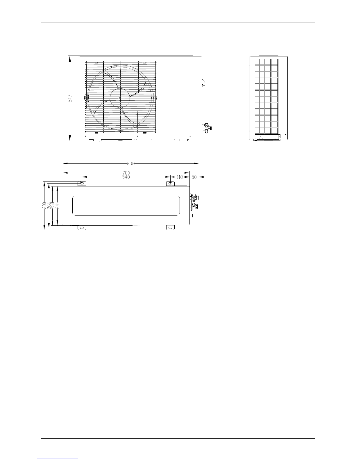
Dimensions MCAC-UTSM-2008-11
94 Outdoor Units
2. Dimensions
2.1 MOU-12HN1
Page 97
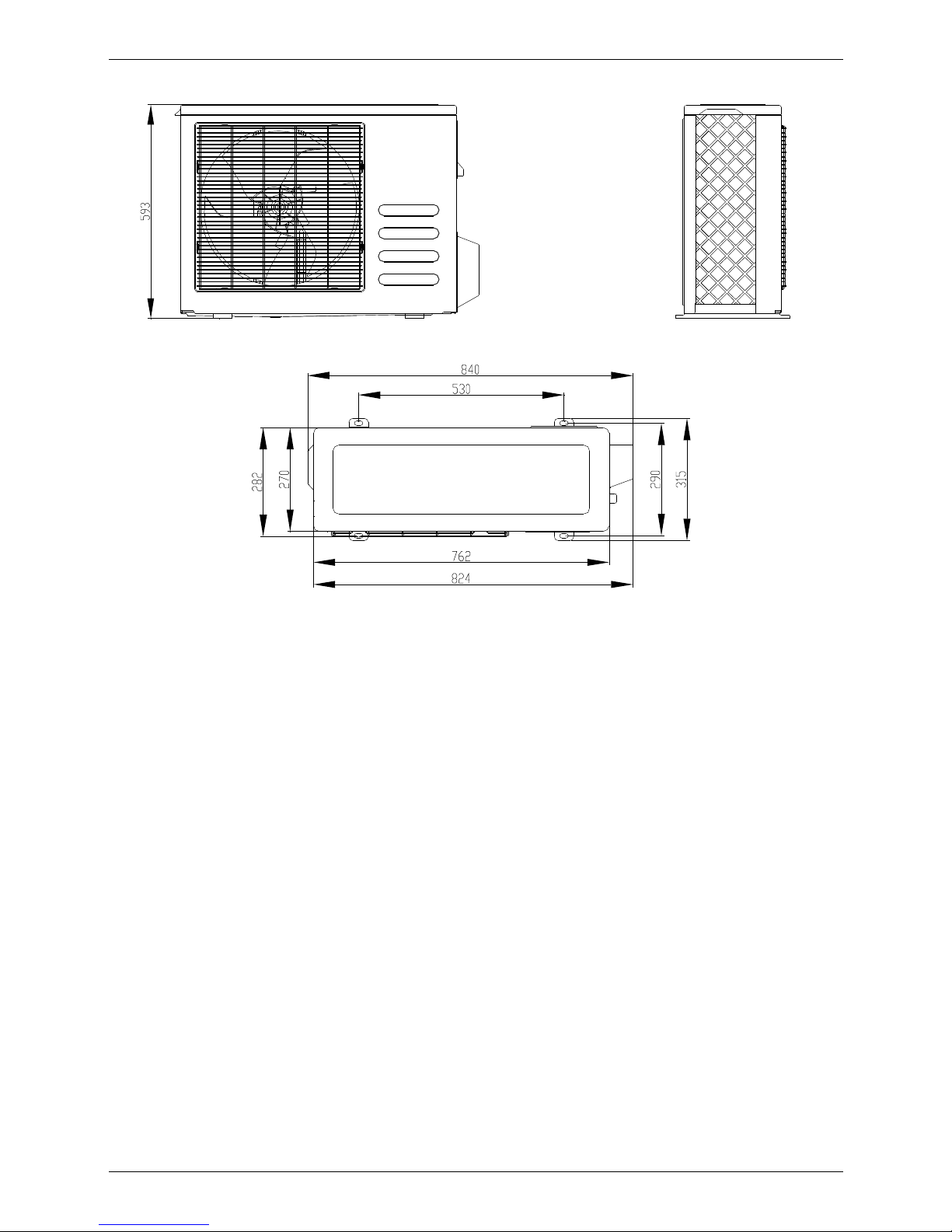
MCAC-UTSM-2008-11 Dimensions
Outdoor Units 95
2.2 MOUA-18HN1
Page 98

Dimensions MCAC-UTSM-2008-11
96 Outdoor Units
2.3 MOUA-24HN1
Page 99
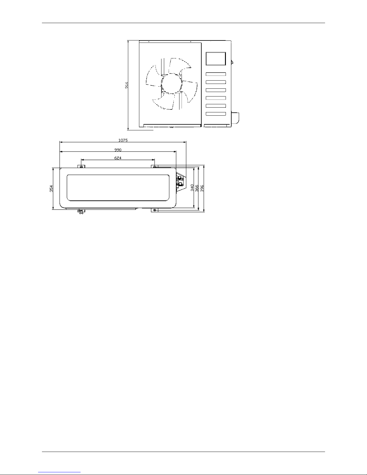
MCAC-UTSM-2008-11 Dimensions
Outdoor Units 97
2.4 MOU-30HN1 MOU-30HN1-R MOU-36HN1 MOU-36HN1-R
Page 100

Dimensions MCAC-UTSM-2008-11
98 Outdoor Units
2.5 MOUA-48HN1-R MOUA-60HN1-R
 Loading...