

Page 1

Portable Air Conditioner
Rated voltage: 115V
Frequency: 60Hz
en
USER MANUAL
Warning notices: Before using
this product, please read this
manual carefully and keep it
for future reference.
The design and specifications
are subject to change without
prior notice for product
improvement. Consult with
your dealer or the manufacturer
for details.
MAP08R1CWT
Customer service: 1(866)-646-4332
WWW.MIDEA.COM
Page 2

Owner’s Manual
Safety Precautions ....................................................................................... 3
Unit Specifications and Features .............................................................. 6
Operating Instructions ................................................................................ 7
Installation Instructions ............................................................................. 10
Care and Cleaning ....................................................................................... 15
Troubleshooting Tips ................................................................................. 16
Remote Control Instructions ..................................................................... 17
Warranty ....................................................................................................... 27
Read This Manual
Inside you’ll find many helpful hints on how to use and maintain your air conditioner
properly. Just a little preventive care on your part can save you a great deal of time
and money over the life of your air conditioner. You’ll find many answers to common
problems in the chart of troubleshooting tips - you should be able to fix most of
them quickly before calling service. These instructions may not cover every possible
condition of use, so common sense and attention to safety is required when installing,
operating and maintaining this product.
CAUTION
• Contact an authorized service technician for repair or maintenance of this unit.
• The unit is not designed to be used by young children or people with reduced
physical, sensory or mental capabilities without supervision.
• Young children should be supervised to ensure that they do not play with the unit.
• If the power cord needs to be replaced, please contact our consumer service or an
authorized technician.
• Electrical installation, if needed, must be performed in accordance to national
regulation standards by qualified personnel only.
Page 2
Page 3

Safety Precautions
To prevent injury to the user or personal and property damage, these instructions must
be followed. Incorrect operation due to ignoring of instructions may cause harm or
damage. The level of risk is shown by the following indications.
Precautions
Safety
This symbol indicat
WARNING
es the possibility of death or serious injury.
This symbol indicates the possibility of injury or damage to property.
CAUTION
This symbol shows that this appliance uses a flammable refrigerant.
If the refrigerant is leaked and exposed to an external ignition source,
WARNING
there is a risk of fire.
This symbol shows that the operation manual should be read carefully.
CAUTION
This symbol shows that a service personnel should be handling this
CAUTION
equipment with reference to the installation manual.
This symbol shows that information is available such as the operating
CAUTION
manual or installation manual.
WARNING
Please read through these instructions before you start the installation process.
Improper installation can cause damage to the unit and/or personal property and
can be a personal safety hazard.
• Installation must be performed according to the installation instructions.
Improper installation can cause water leakage, electrical shock, or fire.
• Use only the included accessories and parts, and specified tools for the
installation. Using non-standard parts can cause water leakage, electrical shock,
fire, and injury or property damage.
• Make sure that the outlet you are using is grounded and has the appropriate
voltage. The power cord is equipped with a three-prong grounding plug to
protect against shock. Voltage information can be found on the side of the unit,
behind the grille.
• Install the unit on a flat, sturdy surface. Failure to do so could result in damage
or excessive noise and vibration.
• The unit must be kept free from obstruction to ensure proper functioning and to
mitigate safety hazards.
• DO NOT modify the length of the power cord or use an extension cord to power
the unit. DO NOT share a single outlet with other electrical appliances. Improper
power supply can cause fire or electrical shock.
Page 3
Page 4

Precautions
Safety
WARNING
• DO NOT install your air conditi
room. Exposure to water can cause electrical components to short circuit.
• DO NOT install the unit in a location that may be exposed to combustible gas, as
this could cause fire.
• The unit has wheels to allow it to move. Do not attempt to roll the unit across
thick carpet or to roll over objects, as this could cause the unit to tip over.
• DO NOT attempt to operate a unit that has been dropped or damaged.
• DO NOT allow children to play with the air conditioner. Children must be
supervised around the unit at all times.
• If the air conditioner is knocked over during use, turn off the unit and unplug it
from the main power supply immediately. Visually inspect the unit to ensure there
is no damage. If you suspect the unit has been damaged, contact a technician or
customer service for assistance.
• In a thunderstorm, the unit should be turned off to avoid damage to the machine
due to lightning.
oner in a wet room such as a bathroom or laundry
CAUTION
• This appl
reduced physical, sensory or mental capabilities or lack of experience and
knowledge, unless they have been given supervision or instruction concerning
use of the appliance by a person responsible for their safety.
• If the power cord is damaged, it must be replaced by the manufacturer, its
service agent, or similarly qualified persons in order to avoid a hazard.
• Prior to cleaning or other maintenance, the appliance must be disconnected from
the outlet.
• Do not install the appliance in a location that may be exposed to combustible
gas. If combustible gas accumulates around the unit, it may cause a fire.
• Do not run the power cord under carpeting. Do not cover cord with throw rugs,
runners, or similar coverings. Do not route cord under furniture or appliances.
Arrange cord away from traffic areas so it will not be tripped over.
• To reduce the risk of fire or electric shock, do not use this air conditioner with
any solid-state speed control device.
• The appliance shall be installed in accordance with national wiring regulations.
• Contact the authorized service technician for repair or maintenance of this unit.
• When there are significant differences between features or operation implied by
the remote control illustrations and the actual functions described in the USER
MANUAL, please refer to the descriptions in the USER MANUAL.
• Do not mix old and new batteries.
• Do not mix alkaline, standard (carbon-zinc), or rechargeable (ni-cad, ni-mh, etc.)
batteries.
iance is not intended for use by persons (including children) with
Page 4
Page 5

Safety Precautions
WARNINGS (for using R32 refrigerant only)
• Do not use any means to accelerate the defrosting process or to clean the unit,
other than those recommended by the manufacturer.
• Do not use or store the appliance in spaces with potential ignition sources (for
example: open flames, an operating gas appliance or an operating electric heater).
• Do not pierce or burn refrigerant tubing. Be aware that refrigerants may not
contain an odor.
• Keep ventilation openings clear of obstruction.
• Store the appliance in a way that will prevent mechanical damage from occurring.
• Store the appliance in a well-ventilated area where the room size corresponds to
the room area as specified for operation.
• Any person who is involved with working on or breaking into a refrigerant circuit
should hold a current valid certificate from an industry-accredited assessment
authority, which authorizes their competence to handle refrigerants safely in
accordance with an industry recognized assessment specification.
• Servicing shall only be performed as recommended by the equipment
manufacturer. Maintenance and repair requiring the assistance of other skilled
personnel shall be carried out under the supervision of the person competent
in the use of flammable refrigerants.
• Flammable refrigerant (R32) is used within the air conditioner. When maintaining
or disposing of the air conditioner, the refrigerant (R32) shall be recovered
properly, do not discharge to air directly.
Precautions
Safety
Ca ution : Ris k of fi re/
flam mab le ma t erial s
(Requir ed fo r R 32/R290 units only )
IMPORTANT NOTE: Read this manual
careful ly be fore ins tal lin g or opera tin g
your new air cond iti oning unit . M ake s ure
to s ave t his manual fo r fut ure r efere nce .
Page 5
Page 6

Specifications
and Features
Unit
Unit Specifications and Features
Preparation
control panel
remote signal receptor
horizontal louver control
lever (adjust manually)
NOTE: PHA cannot be
adjusted.
vertical louver control
lever (adjust manually)
NOTE: PHA cannot be
adjusted.
panel
handle
(both sides)
air filter
(behind the grille)
upper air intake
drain outlet
air outlet
lower air intake
Caster
bottom tray
drain outlet
Front Rear
Design and Compliance Notes
Design Notice:
In order to ensure the optimal performance of our products, the design specifications of
the unit and remote control are subject to change without prior notice.
Energy Rating Information:
This product is tested in accordance to the DOE SACC capacity energy rating test.
Unit Temperature Range:
Mode
Cool
Dry
Exhaust Hose Installation:
The exhaust hose and adapter must be installed or removed according to the
desired mode.
For COOL mode must be installed exhaust hose.
For FAN or Dry modes, must be removed exhaust hose.
Temperature Range
62°F ~ 95°F (17°C ~ 35°C)
55°F ~ 95°F (13°C ~ 35°C)
Page 6
Page 7

Operating Instructions
Control Panel Features
Constant fan
Instructions
Operating
Mode button
CONSTANT FAN(Press 3 s)
Selects the desired operating mode.
Each time you press the button, a mode
is selected in a sequence that goes from
COOL, FAN and DRY. The mode light
illuminates and indicates the selected
mode.
NOTE
On above modes, the unit operates the
auto fan speed automatically. You can
set fan speed only by the remote
control on COOL and FAN modes.
Up (+) and Down (-) buttons
Used to adjust (increasing/decreasing)
temperature settings in 1°C/1°F increments
in a range of 17°C/62°F to 30°C/86°F.
NOTE
The control is capable of displaying
temperature in degrees Fahrenheit or
degrees Celsius. To convert from one
to the other, press and hold the up
and down buttons at the same time
for 3 seconds.
Power button
Power switch on/off.
LED display
em
e
oom
E1 om r
E2 r
E3 r
E4 r
P1
erat
e
Power
indicator light
Timer mode indicator
light (set only by
remote control)
NOTE
When one of the above malfunctions
occurs, turn off the unit and check for
any obstructions. Restart the nit. If the
malfunction persists, turn off the unit
and unplug the power cord.
Page 7
Page 8

Operating Instructions
COOL operation
• Press the “MODE” button until the “COOL”
indicator light comes on.
• Press the ADJUST buttons “+” or “-” to
select your desired room temperature. The
temperature can be set within a range of
Instructions
17°C~30°C/62°F~86°F.
Operating
• Press the “FAN SPEED” button to choose
the fan speed.
DRY operation
• Press the “MODE” button until the “DRY”
indicator light comes on.
• While in this mode, you cannot select a
fan speed or adjust the temperature. The
fan motor operates at LOW speed.
• Keep windows and doors closed for the
best dehumidifying effect.
• Do not connect the duct to a window.
FAN operation
• Press the “MODE” button until the ”FAN“
indicator light comes on.
• Press the “FAN SPEED” button to
the fan speed. The temperature cannot
be adjusted.
• Do not connect the duct to a window.
Other Features
SLEEP operation
This feature can be activated from
the remote
SLEEP feature, the set temperature will
increase by 1°C/2°F in 30 minutes. The set
temperature will then increase by another
1°C/2°F after an additional 30 minutes.
This new temperature will be maintained
for 7 hours before it returns to the
originally selected temperature. This ends
the Sleep mode and the unit will continue
to operate as originally programmed.
NOTE
This feature is not available in FAN or
DRY mode.
FOLLOW ME/TEMP SENSING
Feature (optional)
control ONLY. To activate
choose
NOTE
This feature can be activated from
the remote control ONLY. The remote
control serves as a remote thermostat
allowing for the precise temperature
control at its location.
To activate the Follow Me/Temp Sensing
feature, point the remote control towards
the unit and press the Follow Me/Temp
Sensing button. The remote display is actual
temperature at its location. The remote
control will send this signal to the air
conditioner every 3 minutes until the Follow
Me/Temp Sensing button is pressed again.
If the unit does not receive the Follow Me/
Temp Sensing signal for 7 minutes, the unit
will beep to indicate the Follow Me/Temp
Sensing mode has ended.
Constant Fan button In cooling or Dry
mode, press the button for 3 seconds to
CONSTANT FAN(Press 3s)
turn on or off the constant fan function.
When the function is turned on, the
constant fan light will illuminate,
identifying the fan continuous run for
cooling. When the function is turned off,
the constant fan light will go out,
identifying the fan cycle run with
compressor stop.
AUTO-RESTART
If the unit breaks off unexpectedly due
to the power cut, it will restart with the
previous function setting automatically
when the power resumes.
WAIT 3 MINUTES BEFORE RESUMING
OPERATION
After the unit has stopped, it cannot be
restarted until 3 minutes have elapsed.
This is to protect the unit. Operation will
automatically start after 3 minutes.
AIRFLOW DIRECTION ADJUSTMENT
Adjust the air flow direction manually:
- The louver can be set to the desired
position manually.
- Do not place any heavy objects or
other loads on the louver, doing so will
cause damage to the unit.
- Keep the louver fully opened during
operation.
Page 8
Page 9

Remove the
drain plug
Water drainage
• During dehumidifying modes, remove the drain
plug from the back of the unit and install the drain
connector (5/8” universal female mender) with 3/4”
hose (locally purchased). For models without drain
connector, just attach the drain hose to the hole. Place
the open end of the hose directly over the drain area in
your basement floor.
Instructions
Operating
Continuous
drain hose
NOTE
Make sure the hose is secure so there are
no leaks. Direct the hose toward the drain,
making sure that there are no kinks that
will stop the water flowing. Place the end
of the hose into the drain and make sure
the end of the hose is down to let the
water flow smoothly. When the
continuous drain hose is not used, ensure
that the drain plug and knob are installed
firmly to prevent leakage.
• When the water level of the bottom tray reaches
a predetermined level, the unit beeps 8 times.
The digital display shows “P1.” At this time the
air conditioning/dehumidification process will
immediately stop. However, the fan motor will
continue to operate (this is normal). Carefully move
the unit to a drain location, remove the bottom
drain plug and let the water drain away. Reinstall
the bottom drain plug and restart the machine until
the “P1” symbol disappears. If the error repeats, call
for service.
NOTE
Be sure to reinstall the bottom drain plug firmly to
prevent leakage before using the unit.
Bottom drain plug
Page 9
Page 10

Instructions
Installation
Installation Instructions
Choosing the Right Location
Your installation location should meet the following
requirements:
19.7inch
50cm
Recommended Installation
• Make sure that you install your unit on an even surface
to minimize noise and vibration.
• The unit must be installed near a grounded plug, and
the Collection Tray Drain (found on the back of the
unit) must be accessible.
• The unit should be located at least 12" (30 cm) from
the nearest wall to ensure proper air conditioning. The
horizontal louver blade should be at least 19.7" (50 cm)
away from obstacles.
• DO NOT cover the Intakes, Outlets or Remote Signal
Receptor of the unit, as this could cause damage to
the unit.
NOTE
All the illustrations in the manual are for explanation
purpose only. Your machine may be slightly
different.
The unit can be controlled by the unit control panel
alone or with the remote control. See the remote
control Instruction for details.
50cm
19.7inch
Note About Fluorinated Gasses
• This air-conditioning unit is a hermetically sealed unit that contains fluorinated
gasses. For specific information on the type of gas and the amount, please refer
to the relevant label on the unit itself.
• Service, maintenance and repair of this unit must be performed by a certified
technician.
• Product recycling must be done according to local regulations.
Page 10
Page 11

Tools Needed
• Medium Phillips screwdriver
• Tape measure or ruler
• Knife or scissors
• Saw (optional, to shorten window adaptor for narrow windows).
Accessories
Your Window Installation Kit fits windows 67.5-123 cm (26.5”-48”) and can be shortened
for smaller windows.
Part Description
Unit adaptor
Exhaust hose
Window slider adaptor
Bolt
Window slider A
Foam seal A (adhesive)
Foam seal B (adhesive)
Foam seal C (Non-adhesive)
Security bracket and 2 screws
Drain hose
TEMP
remote control and batteries
(For remote control models only)
Quantity
1 pc
1 pc
1 pc
3 pcs
1 set
4 pcs
2 pcs
2 pcs
1 set
1 pc
1 set
Instructions
Installation
Page 11
Page 12

Instructions
Installation
Window Installation Kit
Exhaust hose Exhaust hose
Unit
adaptor
Window slider
adaptor
assembly
ne: Preparing the exhaust hose
Step O
assembly
Press the exhaust hose into the window
slider adaptor and unit adaptor, clamp
automatically by elastic buckles of the
adaptors.
Step Two: Install the exhaust hose
assembly to the unit
Push the Exhaust hose into the air
outlet opening of the unit along the
arrow direction.
Window Sliders
1+2:
1+2+3:
1+2+3+4:
1+4:
Before assembly
After assembly
Bolt
Bolt
Bolt
BoltBolt
Bolt
Bolt
Step Three: Preparing the adjustable
window slider
1. Depending on the size of your window,
you may need to adjust the size of the
window slider.
f the length of the window requires
2. I
two window sliders, use the bolt to
fasten the window sliders once they
are adjusted to the proper length.
NOTE
Once the Exhaust Hose assembly and
Adjustable Window Slider are prepared,
choose from one of the following two
installation methods.
Page 12
Page 13

Window Installation Kit (cont.)
Foam seal B
(Adhesive type-shorter)
Foam
seal A
(Adhesive
type)
Window
slider A
Foam seal C
(Non-adhesive type)
Window
slider B
(if required)
Type 1: Hung window installation
1. Cut the adhesive foam seal A and B strips to the
proper lengths, and attach them to the window sash
and frame as shown.
2. Insert the window slider assembly into the window
opening.
3. Cut the non-adhesive foam seal C strip to match the
width of the window. Insert the seal between the glass
and the window frame to prevent air and insects from
getting into the room.
Instructions
Installation
2 Screws
Security Bracket
4. If desired, install the security bracket with 2 screws as
shown.
5. Insert the window slider adaptor into the hole of the
window slider.
Page 13
Page 14

Instructions
Installation
Foam seal A
(Adhesive
type)
(Non-adhesive type)
Foam seal B
(Adhesive
type-shorter)
Window slider B
(if required)
Window slider A
Foam seal C
Type 2: Sliding window installation
1. Cut the adhesive foam seal A and B strips to the
proper lengths, and attach them to the window sash
and frame as shown.
2. Insert the window slider assembly into the window
opening.
3. Cut the non-adhesive foam seal C strip to match the
window height. Insert the foam seal between the glass
and the window frame to prevent air and insects from
getting into the room.
4. If desired, install the security bracket with 2 screws
as shown.
2 Screws
Security
Bracket
5. Insert the window slider adaptor into the hole of the
window slider.
NOTE
To ensure proper functioning, DO NOT overextend or bend the hose. Make sure that
there is no obstacle around the air outlet of the exhaust hose (in the range of approx.
20 inches) in order for the exhaust system to work properly. All illustrations in this
manual are for explanation purposes only. Your air conditioner may be slightly
different than the illustrations shown here.
Page 14
Page 15

Care and Cleaning
Safety Precautions
• Always unplug the unit before cleaning or servicing.
• DO NOT use flammable liquids or chemicals to clean the unit.
• DO NOT wash the unit under running water. Doing so causes electrical danger.
• DO NOT operate the machine if the power supply was damaged during cleaning.
A damaged power cord must be replaced with a new cord from the manufacturer.
Clean the Air Filter
Air filter
(take out)
Maintenance Tips
• Be sure to clean the air filter every 2 weeks for
optimal performance.
• The water collection tray should be drained
immediately after P1 error occurs, and before
storage to prevent mold.
• In households with animals, you will have to
periodically wipe down the grill to prevent
blocked airflow due to animal hair.
CAUTION
Remove the air filter
DO NOT operate the unit without fi lter because
dirt and lint will clog it and reduce performance.
Clean the Unit
Clean the unit using a damp, lint-free cloth and mild detergent. Dry the unit with a dry,
lint-free cloth.
Store the Unit When Not in Use
• Drain the unit’s water collection tray according to the instructions in the following section.
• Run the unit on FAN mode for 12 hours in a warm room to dry it and prevent mold.
• Turn off the unit and unplug it.
• Clean the air filter according to the instructions in the previous section. Reinstall the
clean, dry filter before storing.
• Remove the batteries from the remote control.
Care and
Cleaning
NOTE
Be sure to store the unit in a cool, dark place. Exposure to direct sunlight or extreme
heat can shorten the lifespan of the unit.
Page 15
Page 16

Troubleshooting Tips
Malfunction Diagnosis
P
lease check the following troubleshooting methods before calling for service:
Problem Possible Cause Troubleshooting
P1 Error Code. The water collection tray is full.
Turn off the unit, drain the water
from the water collection tray
and restart the unit.
Reset the temperature.
Turn off the unit and clean the
filter according to instructions.
Turn off the unit, disconnect the
hose, check for blockage and
reconnect the hose.
inspect the unit and top off
refrigerant.
Make sure all windows and doors
are closed.
Remove the heat sources if
possible.
surface.
Turn off the unit and clean the
filter according to instructions.
This is normal.
Troubleshooting
Tips
Unit does not
turn on when
pressing ON/
OFF button
Unit does not
cool well
The unit is
noisy and
vibrates too
much
The unit makes
a gurgling
sound
In COOL mode: room temperature
is lower than the set temperature.
The air filter is blocked with dust
or animal hair.
Exhaust hose is not connected or
is blocked.
The unit is low on refrigerant. Call a service technician to
Temperature setting is too high. Decrease the set temperature.
The windows and doors in the
room are open.
The room area is too large. Double-check the cooling area.
There are heat sources inside the
room.
The floor is not level. Place the unit on a flat, level
The air filter is blocked with dust
or animal hair.
This sound is caused by the flow
of refrigerant inside the unit
Page 16
Page 17
Remote Control Instructions
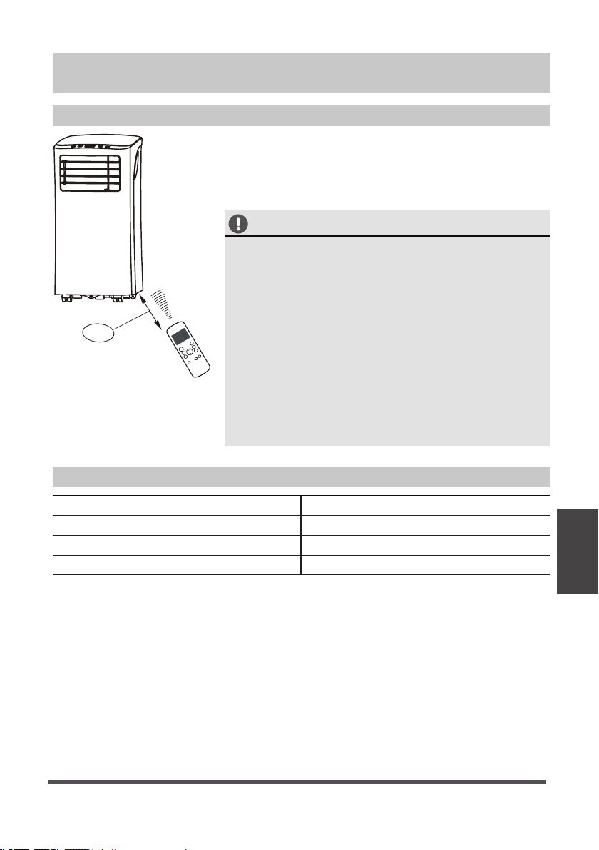
Using The Remote Control
Location of the remote control
the remote control within a distance of 8 meters /
Use
26 feet from the appliance, pointing it towards the
receiver. Reception is confirmed by a beep.
CAUTION
• The air conditioner will not operate if curtains, doors
or other materials block the signals from the remote
control to the indoor unit.
• Prevent any liquid from falling into the remote control.
Do not expose the remote control to direct sunlight
8m
P
M
TE
Remote Control Specifications
or heat.
• If the infrared signal receiver on the indoor unit is
exposed to direct sunlight, the air conditioner may
not function properly. Use curtains to prevent the
sunlight from falling on the receiver.
• If other electrical appliances react to the remote
control, either move these appliances or call customer
support.
Model RG57H3(B)/BGCEFU1-M
Rated voltage 3.0V (Dry batteries R03/LR03x2)
Signal receiving range 8 m (appox. 26 ft.)
Environment
-5°C ~ 60°C (23°F ~ 140°F)
Page 17
(With Remote)
Instructions
Operating
Page 18

Function Buttons
Before you begin using your new air conditioner, make sure to familiarize yourself with
its remote control. The following is a brief introduction to the remote control itself. For
instructions on how to operate your air conditioner, refer to the Operating Instructions
section of this manual.
(With Remote)
Instructions
Operating
Turns the unit on or off.
Scrolls through operation modes
AUTO COOL DRY HEAT FAN
NOTE:
Please do not select HEAT mode
if the machine you purchased is
cool-only type. Heat mode is not
supported by the cool-only models.
Selects fan speeds in the
AUTO LOW MED HIGH
ON/OFF
MODE
as follows:
FAN SPEED
following order:
Saves energy during
SLEEP
sleeping hours.
Optional
ON /O F F
MODE
FAN
SLEEP
T E MP
FOLLOW
ME
SHORT
CUT
TIMER
ON
TIMER
OFF
LED
SHORT CUT
Sets and activates your favorite pre-settings.
TEMP
Increases temperature in 1°C (1°F) increments.
Max. temperature is 30°C (86°F).
TEMP
Decreases temperature in 1°C (1°F) increments.
Min. temperature is 17°C (62°F).
NOTE: Pressing and hold and buttons
together for 3 seconds will alternate the
temperature display between the °C & °F scale.
TIMER ON
Sets timer to turn unit on (see How to Use
Basic Functions for instructions)
TIMER OFF
Sets timer to turn unit off (see How to Use
Basic Functions for instructions)
LED
Turns indoor unit’s LED display on and off.
If you are sensitive to light while sleeping,
you can press the LED button to turn off the
LED display on the unit. Press the button
again to turn it back on.
FOLLOW ME
Temperature sensing and room
temperature display button.
Page 18
Page 19

Handling the Remote Control
NOT SURE WHAT A FUNCTION DOES?
Refer to the Operating Instructions section of this manual for a detailed description of
how to use your air conditioner.
SPECIAL NOTE
Button designs on your unit may differ slightly from the example shown.
If the unit does not have a particular function, pressing that function’s button on the
remote control will have no effect.
When there are significant differences between features or operation implied by the
remote control illustration and the actual functions described in the USER’S
MANUAL, please refer to the descriptions in the USER’S MANUAL.
INSERTING AND REPLACING BATTERIES
Your air conditioning unit comes with two AAA batteries.
Insert the batteries in the remote control before use.
1. Slide the back cover of the remote control downward,
exposing the battery compartment.
2. Insert the batteries, paying attention to align the (+)
and (-) ends of the batteries with the symbols inside
the battery compartment.
3. Slide the battery cover back into place.
BATTERY NOTES
For optimum product performance:
• Do not mix old and new batteries, or batteries of
different types.
• Do not leave batteries in the remote control if you
don’t plan on using the device for more than 2
months.
(With Remote)
Instructions
Operating
BATTERY DISPOSAL
Do not dispose of batteries as unsorted municipal waste.
Refer to local laws for proper disposal of batteries.
TIPS FOR USING REMOTE CONTROL
• The remote control must be used within 8 meters /
26 feet of the unit.
• The unit will beep when remote signal is received.
• Curtains, other materials and direct sunlight can
interfere with the infrared signal receiver.
• Remove batteries if the remote will not be used more
than 2 months.
Page 19
Page 20

Remote LED Screen Indicators
Transmission Indicator
Lights up when remote sends signal to unit
(With Remote)
Instructions
Operating
MODE display
Displays the current
mode, including:
AUTO
COOL
DRY
HEAT
FAN
FAN SPEED display
Displays selected FAN SPEED:
HIGH
MED
LOW
This display is blank when
set to AUTO speed.
ON/OFF display
Appears when the unit is turned on and disappears when it is turned off
TIMER ON display
Displays when
TIMER ON is set
SILENT display
Not available on this unit
Temperature/Timer display
Displays the set temperature by default, or timer setting
when using TIMER ON/OFF functions:
- Temperature range: 17-30°C (62°F-86°F)
- Timer setting range: 0-24 hours
This display is blank when operating in FAN mode.
TIMER OFF display
Displays when
TIMER OFF is set
ECO display
Not available on this unit
Battery display
Low battery detection
SLEEP display
Displays when SLEEP
function is activated
FOLLOW ME display
Indicates that the FOLLOW
ME function is on
Not available on this unit
Page 20
Page 21

Basic Functions
ON/OFF
3
MODE
1
FAN
SLEEP
ON/OFF
4
MODE
1
FAN
3
SLEEP
SHORT
CUT
TIMER
ON
TEMP
TIMER
OFF
FOLLOW
LED
ME
SHORT
CUT
TIMER
ON
TEMP
TIMER
OFF
FOLLOW
LED
ME
SETTING THE DESIRED TEMPERATURE
The operating temperature range for this unit is 17-30°C
(62°F-86°F). You can increase or decrease the set
temperature in 1°C (1°F) increments.
AUTO operation
2
In AUTO mode, the unit will automatically select the COOL,
FAN, HEAT or DRY mode based on the set temperature.
1. Press the MODE button to select Auto mode.
2. Set your desired temperature using the Temp
Temp button.
3. Press the ON/OFF button to start the unit.
NOTE
FAN SPEED cannot be set in AUTO mode.
COOL operation
1. Press the MODE button to select COOL mode.
2. Set your desired temperature using the Temp or
Temp button.
3. Press the FAN button to select the fan speed: AUTO,
2
LOW, MED or HIGH.
4. Press the ON/OFF button to start the unit.
or
(With Remote)
Instructions
Operating
DRY operation (dehumidifying)
1. Press the MODE button to select DRY mode.
2. Set your desired temperature using the Temp
Temp button.
3. Press the ON/OFF button to start the unit.
ON/OFF
3
MODE
1
FAN
SLEEP
SHORT
CUT
TIMER
ON
TEMP
TIMER
OFF
FOLLOW
ME
2
NOTE
LED
FAN SPEED cannot be set in DRY mode.
or
Page 21
Page 22

(With Remote)
Instructions
Operating
Basic Functions (cont.)
ON/OFF
3
MODE
1
2
FAN
SLEEP
ON/OFF
4
MODE
1
3
SLEEP
SHORT
CUT
TIMER
ON
TEMP
TIMER
OFF
FOLLOW
LED
ME
SHORT
CUT
TIMER
ON
TEMP
FOLLOW
ME
TIMER
OFF
FAN
2
LED
FAN operation
1. Press the MODE button to select FAN mode.
2. Press FAN button to select the fan speed: AUTO, LOW,
MED or HIGH.
3. Press the ON/OFF button to start the unit.
NOTE
You cannot set temperature in FAN mode. As a result,
your remote control’s LCD screen will not display
temperature.
HEAT operation
1. Press the MODE button to select HEAT mode.
2. Set your desired temperature using the Temp
Temp button.
or
3. Press the FAN button to select the fan speed: AUTO,
LOW, MED, or HIGH.
4. Press the ON/OFF button to start the unit.
NOTE
As outdoor temperature drops, the performance of your
unit’s HEAT function may be affected. In such instances,
we recommend using this air conditioner in conjunction
with another heating appliance.
Page 22
Page 23

Timer Functions
1 2
TIMER ON TIMER ON
3
1sec
ON/OFF
MODE
SHORT
CUT
FAN
TEMP
TIMER ON
S
L
E
EP
TIMER OF
F
x5
4
2s e c
Example: Setting unit to
turn on after 2.5 hours.
Your air conditioning unit has two timer-related functions:
TIMER ON - sets the amount of time after which the unit
will automatically turn on.
TIMER OFF - sets the amount of time after which the unit
will automatically turn off.
TIMER ON function
The TIMER ON function allows you to set a period of time
after which the unit will automatically turn on, such as when
you come home from work.
1. Press the TIMER ON button. By default, the last time
period that you set and an “h” (indicating hours) will
appear on the display.
NOTE
This number indicates the amount of time you want
to elapse before the unit turns on. For example, if
you set the TIMER ON for 2 hours, “2.0h” will appear
on the screen, and the unit will turn on after 2 hours.
2. Press the TIMER ON button repeatedly to set the time
that you want the unit to turn on.
3. Wait 2 seconds, then the TIMER ON function will be
activated. The digital display on your remote control will
then return to the temperature display.
1
TIMER OFF TIMER OFF
3
ON/OFF
MODE
SHORT
CUT
F
AN
TEMP
TIMER ON
S
LEEP
TIMER OF
F
1sec
2
x10
4
2sec
Example: Setting unit to
turn off after 5 hours.
TIMER OFF function
The TIMER OFF function allows you to set a period of time
after which the unit will automatically turn off, such as when
you wake up.
1. Press the TIMER OFF button. By default, the last time
period that you set and an “h” (indicating hours) will
appear on the display.
NOTE
This number indicates the amount of time you want
to elapse before the unit turns off. For example, if
you set the TIMER OFF for 2 hours, “2.0h” will
appear on the screen, and the unit will turn off after
2 hours.
2. Press the TIMER OFF button repeatedly to set the time
that you want the unit to turn off.
Page 23
(With Remote)
Instructions
Operating
Page 24

Timer Functions (cont.)
3. Wait 2 seconds, then the TIMER OFF function will be
Timer on
ON/OFF
MODE
TEMP
FAN
FOLLOW
SLEEP
Continue
to press
SHORT
CUT
TIMER ON
TIMER
or
ON
TIMER OFF
TIMER
OFF
until desired
time is
reached.
LED
ME
NOTE
activated. The digital display on your remote control will
then return to the temperature display.
When setting the TIMER ON or TIMER OFF functions,
up to 10 hours, the time will increase in 30 minute
increments with each press. After 10 hours and up to
24, it will increase in 1 hour increments. The timer will
revert to zero after 24 hours.
You can turn off either function by setting the timer to
“0.0h“.
1
TIMER ON
2
TIMER ON
X12
3
4
Setting both TIMER ON and
TIMER OFF at the same time
sec
Keep in mind that the time
periods you set for both
functions refer to hours after
the current time.
For example, say that the
current time is 1:00 PM, and
you want the unit to turn on
automatically at 7:00 PM and
sec
want it to operate for 2 hours,
then automatically turn off at
9:00 PM.
Follow the illustration to the
left:
(With Remote)
Instructions
Operating
5
TIMER OFF
6
TIMER OFF
X16
ON/OFF
MODE
SHORT
CUT
TEMP
TIMER ON
7
8
ON/OFF
MODE
SHORT
CUT
TEMP
TIMER ON
Example: Setting the unit to turn on after 6 hours, operate for 2 hours, and then
turn off (see the figure below)
Your remote display
Timer On
Timer Off
Timer is set
To turn ON
6 hours from
current time
Timer is set
To turn OFF
8 hours from
current time
Timer
Starts
Current
Time 1PM
2PM 3PM
4PM 5PM
6 hours later
6PM 7PM 8PM 9PM
8 hours later
Unit turns
ON
Unit turns
OFF
Page 24
Page 25

Advanced Functions
SLEEP Function
The SLEEP function is used to decrease
energy use while you sleep (and don’t need
the same temperature settings to stay
comfortable). This function can only be
activated via remote control.
Note:
The SLEEP function is not
available in FAN or DRY mode.
ON/OFF
MODE
FAN
TEMP
SHORT
CUT
TIMER
ON
TIMER
OFF
SLEEP
FOLLOW
ME
LED
FOLLOW ME Function
The FOLLOW ME function enables the
remote control to measure the
temperature at its current location.
When using AUTO, COOL, or HEAT
functions, measuring ambient
temperature
from the remote control
(instead of from the indoor unit itself)
will enable the air conditioner to
optimize the temperature around you
and ensure maximum comfort.
1. Press FOLLOW ME button to activate
function. The remote control will send
temperature signal to the unit every
three minutes.
2. Press FOLLOW ME button again to
turn off this function.
SHORTCUT Function
Used to restore the current settings or resume
previous settings.
Push this button when remote control is on,
the system will automatically revert back to the
previous settings including operating mode,
setting temperature, fan speed level and sleep
feature (if activated).
By pressing for more than 2 seconds, the
system will automatically restore the current
operation settings including operating mode,
setting temperature, fan speed level and sleep
feature (if activated.
NOTES
• Button configuration shown in illustrations is based on a typical model and may
be slightly different from the actual one you purchased. In this case, please refer
to your purchased remote control.
• All the functions described can also be accomplished by using the unit’s control
panel. If the unit is without this feature, there will be no corresponding operation
when pressing the relevant button on the remote control.
(With Remote)
Instructions
Operating
Page 25
Page 26

NOTE
This equipment has been tested and found to comply with the limits for Class
B digital de
to provide reasonable protection against harmful interference in a residential
installation. This equipment generates, uses and can radiate radio frequency
energy and, if not installed and used in accordance with the instructions, may
cause harmful interference to radio communications. However, there is no
guarantee that interference will not occur in a particular installation. If this
equipment does cause harmful interference to radio or television reception, which
can be determined by turning the equipment off and on, the user is encouraged to
try to correct the interference by one or more of the following measures:
1) Reorient or relocate the receiving antenna.
2) Increase the separation between the equipment and receiver.
3) Connect the equipment to an outlet on a circuit different from that to which the
receiver is connected.
4) Consult the dealer or an experience radio/TV technician for help.
Changes or modifications not approved by the party responsible for FCC compliance
could void the user’s authority to operate the equipment.
This appliance complies with Part 15 of the FCC Rules. Operation is subject to the
following two conditions:
1) This device may not cause harmful interference.
2) This device must accept any interference received, including interference that
may cause undesired operation.
vice, pursuant to Part 15 of the FCC Rules. These limits are designed
(With Remote)
Instructions
Operating
Page 26
Page 27

Warranty
Air Conditioner Limited Warranty
Warranty
•
One Year Limited Warranty from original purchase date. Five Year Limited Sealed System (Sealed system
includes components containing refrigerant) Warranty from original purchase date.
Midea, through its authorized servicers will:
Consumer will be responsible for:
NORMAL RESPONSIBILITIES OF THE CONSUMER**
This warranty applies only to products in ordinary household use, and the consumer is responsible for the items
listed below:
ordance with instructions provided with the product.
connections or defects in house wiring.
EXCLUSIONS
This warranty does not cover the following:
for use or purpose.
NOTE: Some states do not allow the exclusions or limitation of incidental or consequential damages. So this
limitation or exclusion may not apply to you.
IF YOU NEED SERVICE
This written warranty gives you specific legal rights. You may also have other rights that vary from state to state.
Warranty
72 egaP
Page 28

How to Stay Cool with a New Portable Air Conditioner
Because of a new federal test procedure for Portable Air Conditioners, you may
notice that the cooling capacity claims on portable air conditioner packaging are
significantly lower than that of models produced prior to 2017. This is due to
changes in the test procedure, not to the portable air conditioners themselves.
What should I look for first when purchasing a portable air conditioner?
The right air conditioner helps you cool a room efficiently. An undersized unit
won't cool adequately while one that's too large will not remove enough humidity,
leaving the air feeling damp. To find the proper air conditioner, determine the
square footage of the room you want to cool by multiplying the room length by
its width. You also need to know the air conditioner's BTU (British Thermal Unit)
rating, which indicates the amount of heat it can remove from a room. A higher
number means more cooling power for a larger room. (Be sure you are
comparing only newer models to each other- older models may appear to have
a higher capacity, but are actually the same). Be sure to “size up” if your portable
air conditioner will be placed in a very sunny room, in a kitchen, or in a room with
high ceilings. After you’ve found the right cooling capacity or your room, you can
look at other features.
Why is the cooling capacity lower on newer models than on older units?
Federal regulations require manufacturers to calculate cooling capacity based
on a specific test procedure. Models manufactured before 2017 were tested
under a different procedure and cooling capacity is measured differently than
in prior years’ models. So, while the BTUs may be lower, the actual cooling
capacity of the air conditioners has not changed.
What is SACC ?
SACC is the representative value of Seasonally Adjusted Cooling Capacity, in
Btu/h, as determined in accordance with the DOE test procedure at title 10
Code of Federal Regulations (CFR) 430, subpart B, appendix CC and applicable
sampling plans.
Page 29

Page 30

Page 31

Page 32

 Loading...