

Page 1

Midea Precision AC Technical Manual-Down Delivery Series MCAC-RTSM-2013-04
0
Midea Precision Air Conditioner
Technical Manual
(Down delivery series)
Midea reserves the right to discontinue, or change specification or designs at any time without
notices and without incurring obligations.
Page 2

MCAC-PDSM-2013-04 Midea Precision AC Technical Manual-Down Delivery Series
1
Content
1. GENERAL INFORMATION ................................................................... 3
1.1 MEASUREMENTS ............................................................................................................ 3
1.2 EXTERNAL APPEARANCE ................................................................................................. 4
1.3 NOMENCLATURE ............................................................................................................. 5
2. SPECIFICATION & PERFORMANCE .................................................. 6
2.1FEATURES ...................................................................................................................... 6
2.2
REFRIGERANT CIRCUIT .................................................................................................... 8
2.3 SPECIFICATIONS ........................................................................................................... 10
2.4 DIMENSION (UNIT: MM) .................................................................................................. 32
2.5 SERVICE SPACE ............................................................................................................ 36
2.6 WIRING DIAGRAM ......................................................................................................... 37
3. INSTALLATION .................................................................................. 40
3.1 STORAGE ENVIRONMENT ............................................................................................... 42
3.2 INDOOR INSTALLATION ................................................................................................... 42
3.3 INSTALLING OUTDOOR UNITS .......................................................................................... 45
3.4 CONNECTING REFRIGERANT PIPE ................................................................................... 46
3.5 VACUUM AND ADD REFRIGERANT .................................................................................... 49
3.6
WATER PIPE INSTALLATION ............................................................................................ 50
3.7
ELECTRIC CONNECTION ................................................................................................ 52
3.8 TRIAL RUN ................................................................................................................... 55
4. CONTROL SYSTEM ........................................................................... 61
4.1 TABLE OF MAIN CONTROL COMPONENTS AND CONTROL LOAD ............................................ 61
4.2 MAIN CONTROL FUNCTION ............................................................................................. 64
5. OPERATION ....................................................................................... 65
Page 3

Midea Precision AC Technical Manual MCAC-PDSM-2013-01
2
5.1 TEMPERATURE/HUMIDITY SET POINT SETTING FUNCTION .................................................. 65
5.2 QUERY FUNCTION FOR KEY COMPONENTS OPERATING STATUS .......................................... 65
5.3 SETTING FUNCTION OF USING PARAMETERS .................................................................... 67
5.4 MAINTENANCE MANAGEMENT ........................................................................................ 68
5.5 CLOCK MANAGEMENT ................................................................................................... 69
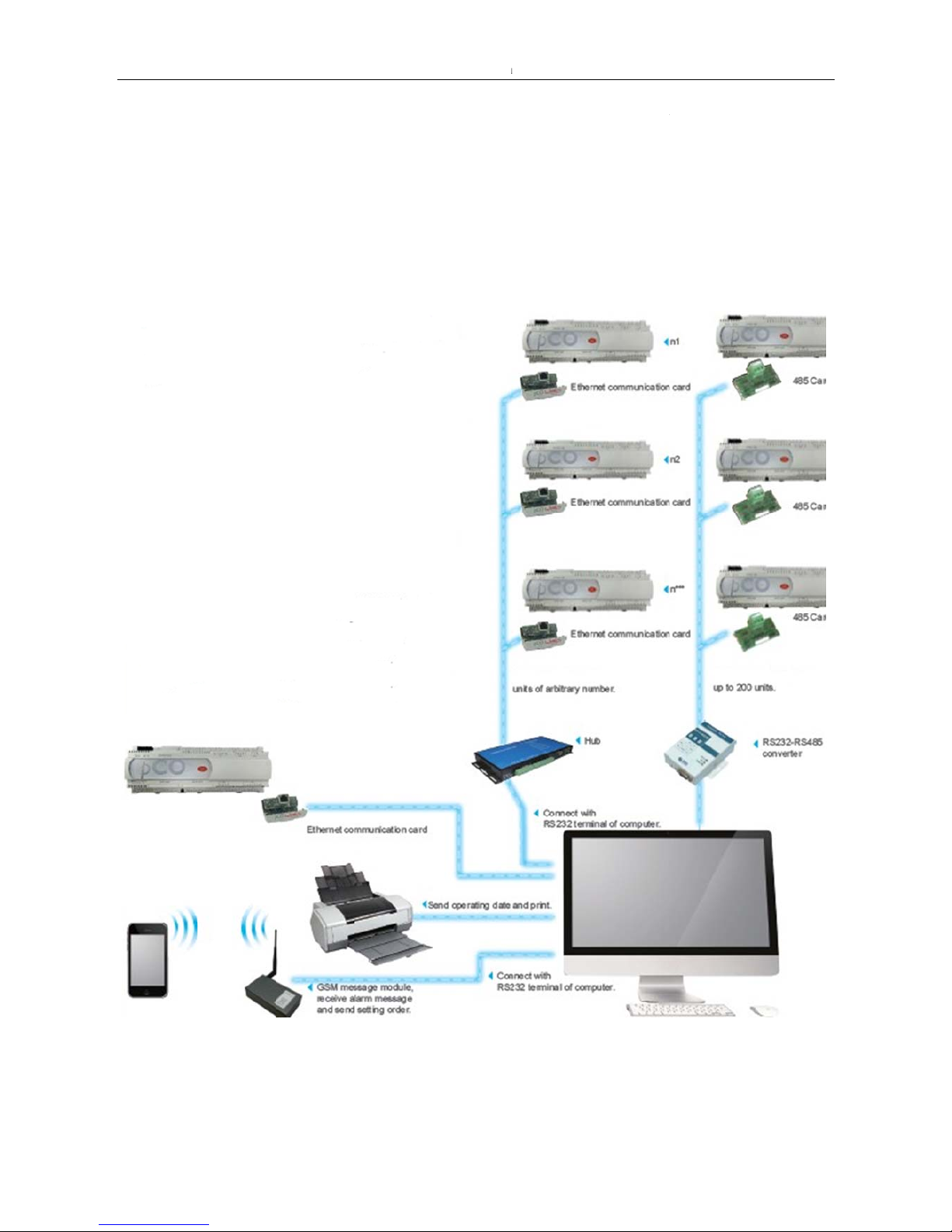
6. NETWORK FUNCTION INTRODUCTION ......................................... 71
6.1 GROUP CONTROL NETWORK SETTING ............................................................................. 72
6.2 THE ETHERNET COMMUNICATION CARD INTRODUCTION .................................................... 78
7. MAINTENANCE .................................................................................. 81
7.1 ELECTRICAL MAINTENANCE ........................................................................................... 81
7.2 CONTROL MAINTENANCE ............................................................................................... 81
7.3 FILTER SCREEN MAINTENANCE ....................................................................................... 82
7.4 INDOOR FAN COMPONENTS MAINTENANCE ...................................................................... 83
7.5 HUMIDIFIER MAINTENANCE ............................................................................................ 83
7.6 ELECTRICAL HEATING COMPONENTS ............................................................................... 85
7.7 REFRIGERATION SYSTEM ............................................................................................... 85
7.8 COMPRESSOR MONITORING AND REPLACEMENT .............................................................. 86
7.9
OUTDOOR FAN MAINTENANCE ........................................................................................ 87
8. TROUBLE SHOOTING ....................................................................... 88
9. ACCESSORIES .................................................................................. 93
ANNEX I: ALARM TABLE ...................................................................... 94
Page 4
MCAC-PDSM-2013-04 Midea Precision AC Technical Manual-Down Delivery Series
3
1. General information
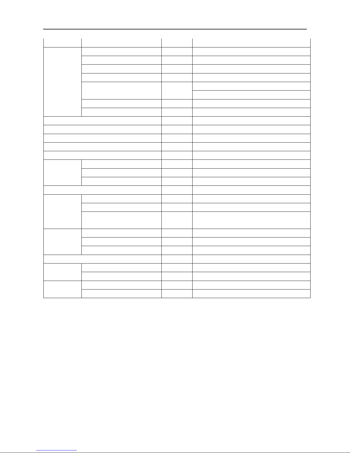
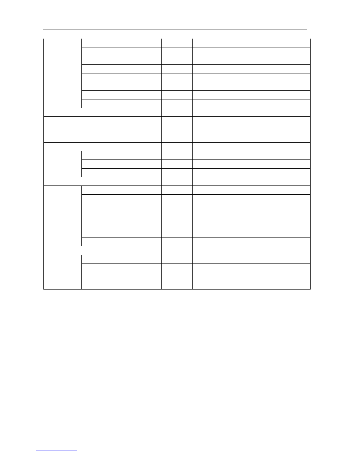
1.1 Measurements
Type Model
Dimension
(mm, W×H×D)
Outdoor unit
(Quantity)
Power Supply
20kW
Indoor MAD020T1N1S1 895×1,971×870
1
380V~,3Ph,50Hz
Outdoor MA0331 1,470×988×870 380V~,3Ph,50Hz
25kW
Indoor MAD025T1N1S1 895×1,971×870
1
380V~,3Ph,50Hz
Outdoor MA0431 1,470×988×870 380V~,3Ph,50Hz
30kW
Indoor MAD030T1N1S1 895×1,971×870
1
380V~,3Ph,50Hz
Outdoor MA0541 1,660×1,290×870 380V~,3Ph,50Hz
35kW
Indoor MAD035T1N1S1 1,400×1,971×870
1
380V~,3Ph,50Hz
Outdoor MA0601 1,660×1,290×870 380V~,3Ph,50Hz
40kW
Indoor MAD040T2N1S1 1,790×1,971×870
2
380V~,3Ph,50Hz
Outdoor MA0331 1,470×988×870 380V~,3Ph,50Hz
45kW
Indoor MAD045T1N1S1 1,790×1,971×870
1
380V~,3Ph,50Hz
Outdoor MA0752 1,980×1,290×870 380V~,3Ph,50Hz
50kW
Indoor MAD050T2N1S1 1,790×1,971×870
2
380V~,3Ph,50Hz
Outdoor MA0431 1,470×988×870 380V~,3Ph,50Hz
60kW
Indoor MAD060T2N1S1 1,790×1,971×870
2
380V~,3Ph,50Hz
Outdoor MA0541 1,660×1,290×870 380V~,3Ph,50Hz
70kW
Indoor MAD070T2N1S1 2,685×1,971×870
2
380V~,3Ph,50Hz
Outdoor MA0601 1,660×1,290×870 380V~,3Ph,50Hz
80kW
Indoor MAD080T2N1S1 2,685×1,971×870
2
380V~,3Ph,50Hz
Outdoor MA0752 1,980×1,290×870 380V~,3Ph,50Hz
90kW
Indoor MAD090T2N1S1 2,685×1,971×870
2
380V~,3Ph,50Hz
Outdoor MA0982 2,480×1,290×870 380V~,3Ph,50Hz
Page 5
Midea Precisi
4
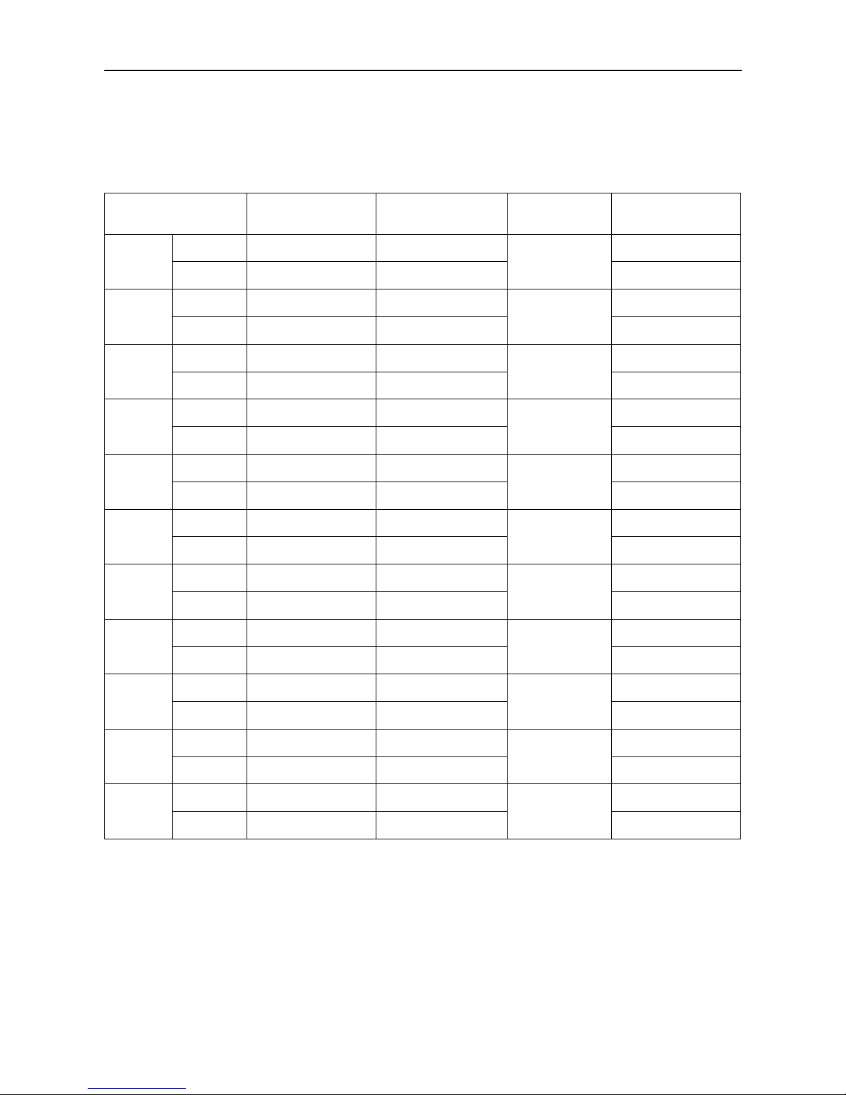
1.2 Exter
n
Indoo
r
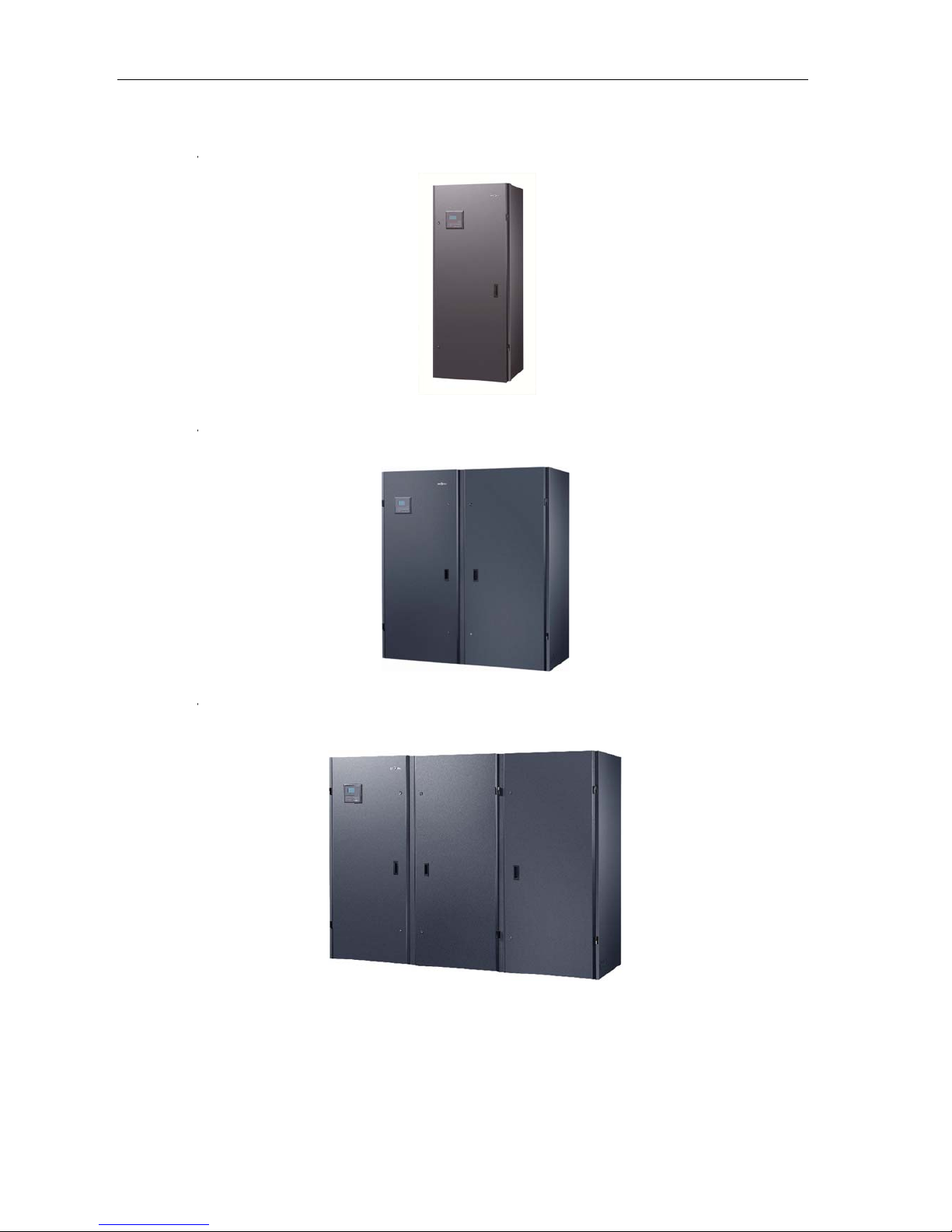
Indoo
r
Indoo
r
on AC Techni
c
al appea
r
unit-20kW
,
unit-35kW
,
unit-70kW
,
c
al Manual
ance
25kW, 30
k
40kW, 45
k
80kW, 90
k
W:
W, 50kW,
6
W:
0kW:
M
MCAC-PDS
M
-2013-01
Page 6
MCAC-PDS
M
Outdo
o
Outdo
o
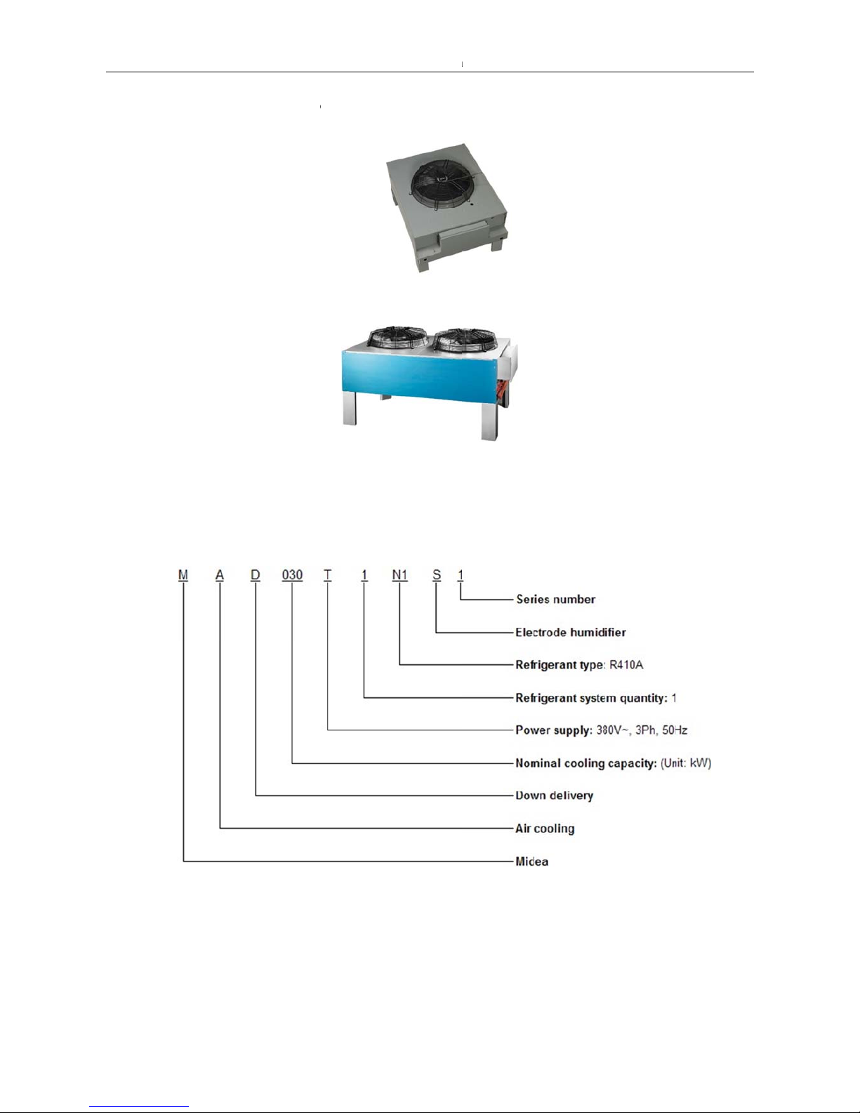
1.3 Nome
Indoor u
n
-2013-04
r unit-Sin
g
r unit-Do
u
nclature
it
le fan mot
o
ble fan mo
r:
tors:
Mide
a
Precision A
C
Technical Manual-Down Delivery Series
5
Page 7
Midea Precisi
6
Outdo
o
2. Spec
i
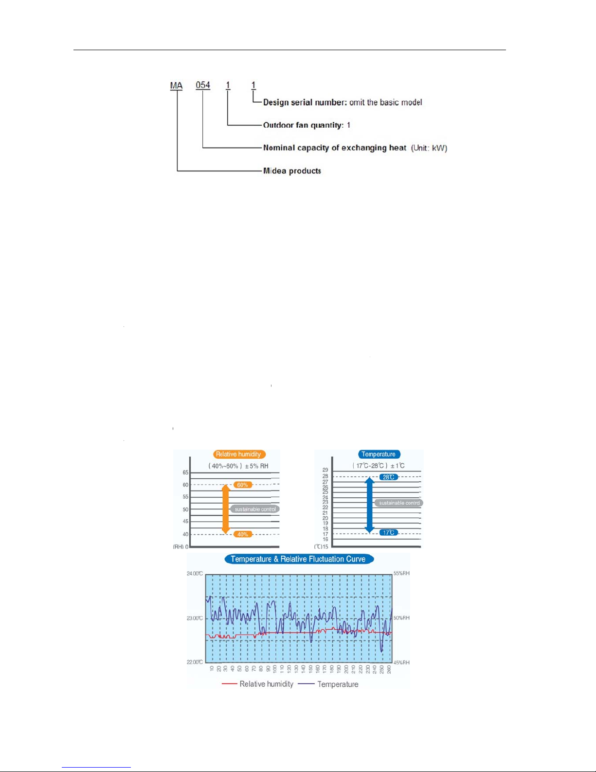
2.1Feature
s
V sha
p
pipe.
Chang
e
tempe
r
Reliabl
e
Doubl
e
from th
Copel
a
Adopt
a
integra
t
Accura
tempe
r
on AC Techni
c
r unit
ficatio
n
e design h
i
the valid
e
ature fluctu
a
electric h
e
wall desig
n
e unit body.
nd, special
dvantage
t
ed control
s
te micropr
o
ature & hu
m
al Manual
& perf
o
gh efficient
vaporator
a
tion.
ater.
, heat-insul
high efficie
n
echnology
o
olution of h
cessor con
t
idity senso
rmanc
e
evaporato
r
rea by ele
c
ated casin
g
t compress
o
f immerse
d
umidity.
rol technol
o
, frequenc
y
with hydr
o
tric valve t
o
reduces th
or.
electrode
gy and ke
converter,
p
philic alumi
reduce th
e
e exchang
e
humidifier,
c
y
parts: Hi
g
ressure se
M
num fin an
d
relative h
u
d heat and
arel clean
a
h quality h
nsor.
MCAC-PDS
M
inner gro
o
midity with
o
prevent th
e
ble steam
c
umidity co
n
-2013-01
ved coppe
ut appare
n
condensat
e
ylinder, an
d
trol modul
e
r
t
,
Page 8
MCAC-PDS
M
Multipl
e
The ru
n
100 pi
e
Three
t
Rotary
whole
y
To en
h
comm
u
capabil
-2013-04
protection
s
ning para
m
ces of erro
r
ypes of pa
s
function, s
t
ear.
ance rem
o
nication ca
r
ities as the
: High and
eter can b
e
records ca
sword: use
r
andby fun
c
te commu
n
d (optional
requiremen
t
low pressu
r
displayed i
be stored.
password,
tion and jo
i
ications a
n
part) and
R
s.
Mide
a
e protectio
n
n the scree
n
maintenan
c
in-in functi
o
nd control
S485 card
Precision A
C
, discharge
of the con
t
e passwor
d
n can ens
u
the precisi
(optional p
a
Technical M
a
temperatur
e
rol panel.
, factory pa
s
re the unit
s
on air con
rt) can sup
nual-Down D
e protectio
n
ssword.
keep ope
ditioners, t
port the co
m
elivery Series
7
, etc.
rating in th
e
he Ethern
e
municatio
n
t
Page 9
Midea Precisi
8
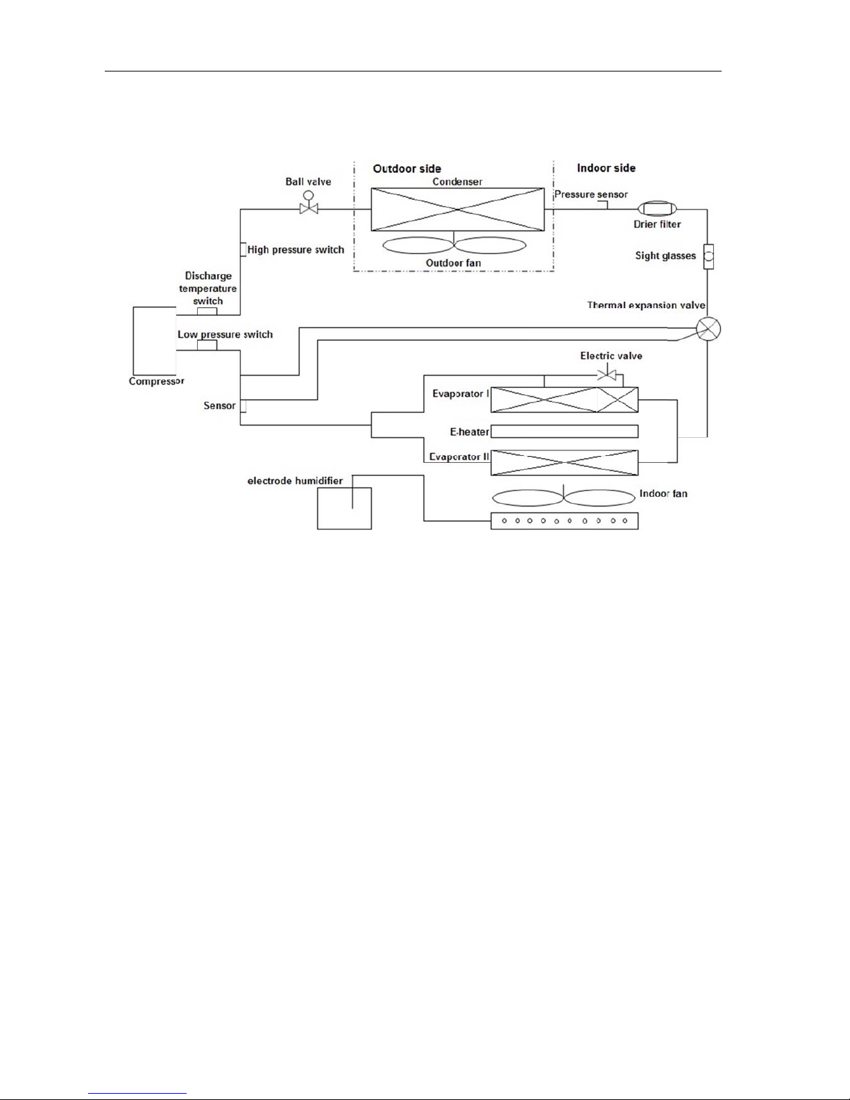
2.2 Refri
g
Single
on AC Techni
c
erant cir
c
refrigeran
t
al Manual
uit
circuit typ
e:
MMCAC-PDSM-2013-01
Page 10
MCAC-PDS
M
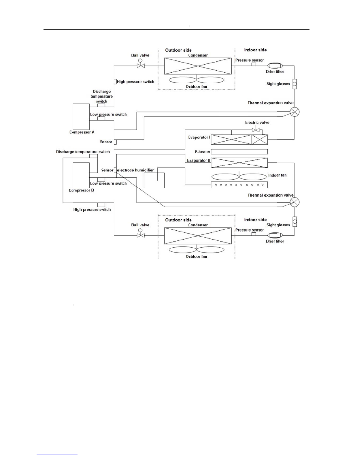
Dual-r
e
Comp
r
Evapo
r
Indoo
r
Outdo
o
-2013-04
frigerant
c
essor: R41
ator (Heat
Fan: Centr
i
r Fan: Axi
a
ircuits typ
e
0A, scroll c
o
exchange
r
fugal fan
l fan
:
mpressor.
): Copper t
u
Mide
a
be and alu
m
Precision A
C
inum fin t
y
Technical M
a
pe heat ex
c
nual-Down D
hanger.
elivery Series
9
Page 11
Midea Precision AC Technical Manual MCAC-PDSM-2013-01
10
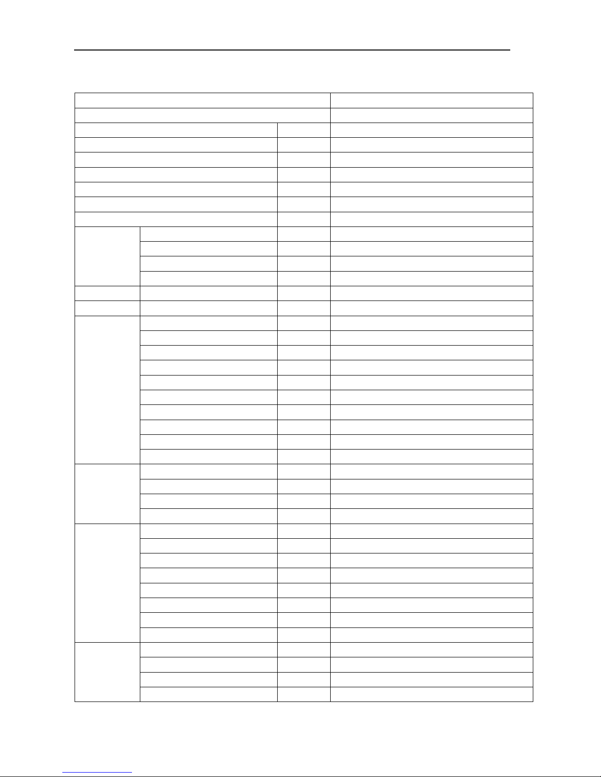
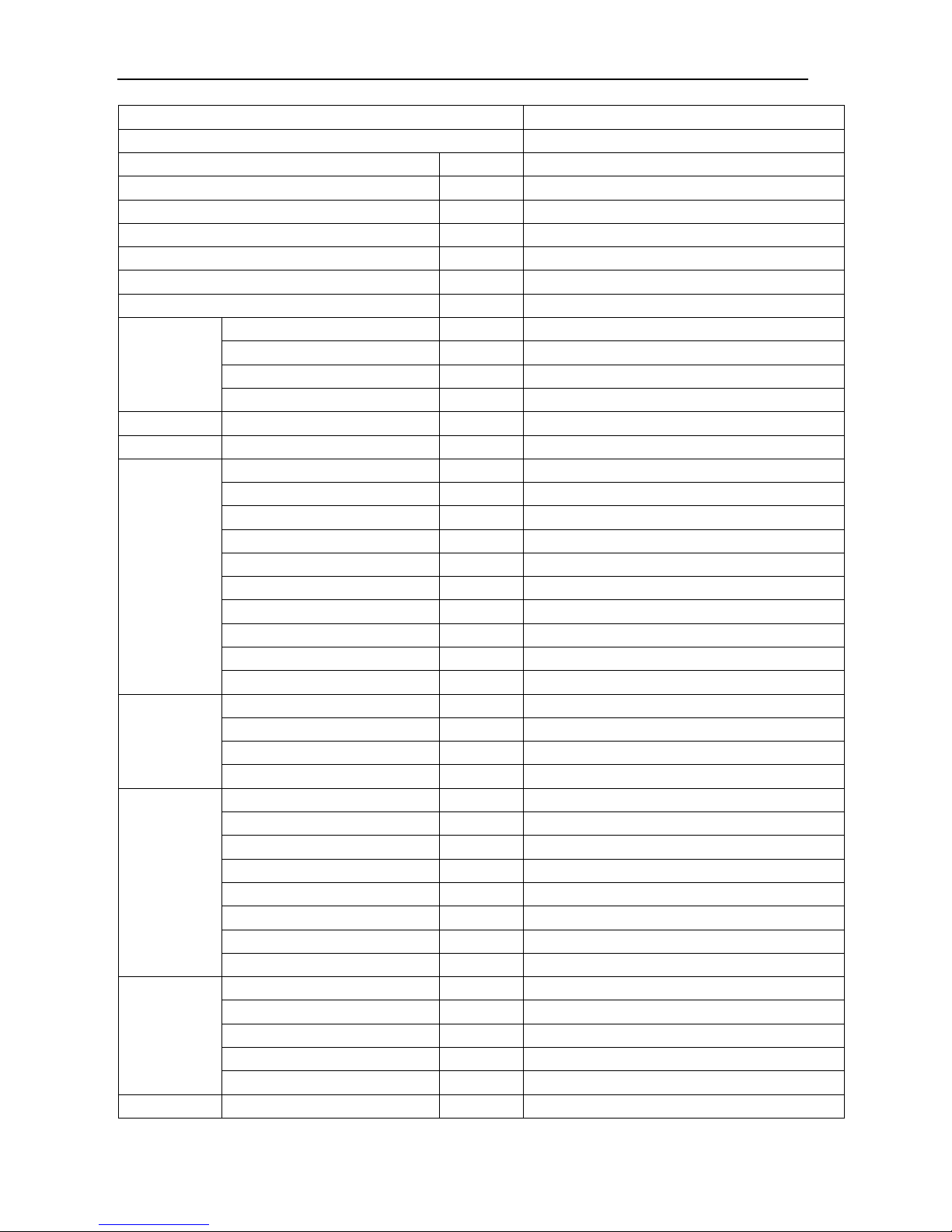
2.3 Specifications
Indoor model
MAD020T1N1S1
Outdoor model (×Quantity)
MA0331 (×1)
Indoor operating ambient temperature range °C 0~40
Outdoor operating ambient temperature range °C -20~45, (-40~45, with low ambient temperature kit)
Altitude \
≤1000m (higher than 1000m, derating use)
Indoor Power supply V, Ph, Hz 380V~,3Ph,50Hz
Outdoor Power supply V, Ph, Hz 380V~,3Ph,50Hz
Whole unit Rated input W 15,000
Whole unit Rated current A 26.8
Cooling
Total capacity W 20,200
Sensible capacity W 18,580
Input W 7,800
EER W/W 2.59
E-heater Capacity W 6,000
Humidification Capacity kg/h 5
Compressor
Model \ ZP83KCE-TFD-522
Type \ Scroll
Qty. \ 1
Brand \ Copeland
Capacity W 20,000
Input W 6,400
Rated current (RLA) A 13.6
Locked rotor Amp (LRA) A 101
Thermal protector \ Internal
Refrigerant oil ml 1,774 (POE)
Indoor fan
Model (× quantity) \ Y(2)100L1-4-2.2KW(YRZ) (×1)
Brand \ Huanqiu/Wolong
Input W 2,200
Speed r/min 1,420
Indoor coil
Number of rows \ 4
Tube pitch(a)×row pitch(b) mm 25.4×22
Fin spacing mm 1.8
Fin type \ Hydrophilic aluminum fin
Pipe size mm Ф9.52
Pipe type \ Inner grooved copper pipe
Coil(W×H) mm (726×686)+(726×686)
Number of circuits \ 9+9
Outdoor fan
Type \ Axial fan
Motor Model (× Quantity) \ FN071-SDK (×1)
Motor Brand \ Ziehl-Abegg
Motor Input W 940
Page 12
MCAC-PDSM-2013-04 Midea Precision AC Technical Manual-Down Delivery Series
11
Speed r/min 900
Outdoor coil
No. of rows \ 3
Tube pitch(a)×row pitch(b) mm 25.4×22
Fin spacing mm 2.2
Fin type \ Hydrophilic aluminum fin
Pipe outside dia. and type mm
Ф9.52
Inner grooved copper pipe
Coil (W×D) mm 1,250×914.4
Number of circuits \ 6
Indoor air flow m3/h 6,225
Indoor external static pressure Pa 20
Indoor drain pipe I.D. mm Ф30
Indoor noise level dB(A)
≤66
Outdoor noise level dB(A)
≤64
Refrigerant
Type \ R410A
Recharged (After installation) g 7,500
Control \ Thermostatic expansion valve
Maximum refrigeration pipe pressure MPa 4.4
Refrigerant
pipe
Max. pipe length m 60
Max. difference in level (O.U. up) m 20
Max. difference in level (O.U.
down)
m 5
Connection
wire
Indoor power wire mm2
3×10.0mm
2
(A,B,C)+2×6.0mm2(N,GND)
Outdoor power wire mm2 4×1.0mm2
Signal wire mm2 4×1.0mm2
Filter \ G4
Indoor unit
Net dimension (W×H×D) mm 895×1,971×870
Net weight kg 340
Outdoor unit
Net dimension (W×H×D) mm 1,470×988×690(No include supporting bar)
Net weight kg 105
Notes:
1. The nominal cooling capacity is based on the following conditions. Indoor temperature: 24°CDB, 17°CWB;
Outdoor temperature: 35°CDB, pipe length is 10 meters.
2. The noise is measured in the semi suppression lab.
3. Specifications are subject to change without prior notice for product improvement.
Page 13
Midea Precision AC Technical Manual MCAC-PDSM-2013-01
12
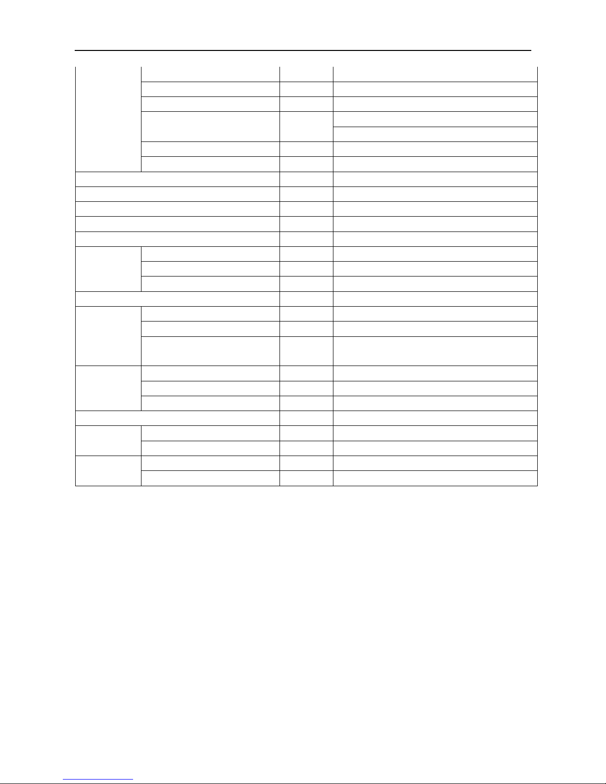
Indoor model
MAD025T1N1S1
Outdoor model (×Quantity)
MA0431 (×1)
Indoor operating ambient temperature range °C 0~40
Outdoor operating ambient temperature range °C -20~45, (-40~45, with low ambient temperature kit)
Altitude \
≤1000m (higher than 1000m, derating use)
Indoor Power supply V, Ph, Hz 380V~,3Ph,50Hz
Outdoor Power supply V, Ph, Hz 380V~,3Ph,50Hz
Whole unit Rated input W 16,500
Whole unit Rated current A 30
Cooling
Total capacity W 26,000
Sensible capacity W 23,920
Input W 9,400
EER W/W 2.77
E-heater Capacity W 6,000
Humidification Capacity kg/h 5
Compressor
Model \ ZP103KCE-TFD-522
Type \ Scroll
Qty. \ 1
Brand \ Copeland
Capacity W 25,200
Input W 7,800
Rated current (RLA) A 18.6
Locked rotor Amp (LRA) A 111
Thermal protector \ Internal
Refrigerant oil ml 3,253 (POE)
Indoor fan
Model (× quantity) \ Y(2)100L2-4-3KW(YRZ) (×1)
Brand \ Huanqiu/Wolong
Input W 3,000
Speed r/min 1,420
Indoor coil
Number of rows \ 4
Tube pitch(a)×row pitch(b) mm 25.4×22
Fin spacing mm 1.8
Fin type \ Hydrophilic aluminum fin
Pipe size mm Ф9.52
Pipe type \ Inner grooved copper pipe
Coil(W×H) mm (726×686)+(726×686)
Number of circuits \ 9+9
Outdoor fan
Type \ Axial fan
Motor Model (× Quantity) \ FN080-ADK (×1)
Motor Brand \ Ziehl-Abegg
Motor Input W 1,100
Speed r/min 680
Outdoor coil No. of rows \ 3
Page 14

MCAC-PDSM-2013-04 Midea Precision AC Technical Manual-Down Delivery Series
13
Tube pitch(a)×row pitch(b) mm 25.4×22
Fin spacing mm 2.2
Fin type \ Hydrophilic aluminum fin
Pipe outside dia. and type mm
Ф9.52
Inner grooved copper pipe
Coil (W×D) mm 1,250×914.4
Number of circuits \ 6
Indoor air flow m3/h 7,010
Indoor external static pressure Pa 20
Indoor drain pipe I.D. mm Ф30
Indoor noise level dB(A)
≤66
Outdoor noise level dB(A)
≤64
Refrigerant
Type \ R410A
Recharged (After installation) g 9,500
Control \ Thermostatic expansion valve
Maximum refrigeration pipe pressure MPa 4.4
Refrigerant
pipe
Max. pipe length m 60
Max. difference in level (O.U. up) m 20
Max. difference in level (O.U.
down)
m 5
Connection
wire
Indoor power wire mm
2
3×10.0mm
2
(A,B,C)+2×6.0mm2(N,GND)
Outdoor power wire mm2 4×1.0mm2
Signal wire mm2 4×1.0mm2
Filter \ G4
Indoor unit
Net dimension (W×H×D) mm 895×1,971×870
Net weight kg 360
Outdoor unit
Net dimension (W×H×D) mm 1,470×988×690(No include supporting bar)
Net weight kg 105
Notes:
1. The nominal cooling capacity is based on the following conditions. Indoor temperature: 24°CDB, 17°CWB;
Outdoor temperature: 35°CDB, pipe length is 10 meters.
2. The noise is measured in the semi suppression lab.
3. Specifications are subject to change without prior notice for product improvement.
Page 15

Midea Precision AC Technical Manual MCAC-PDSM-2013-01
14
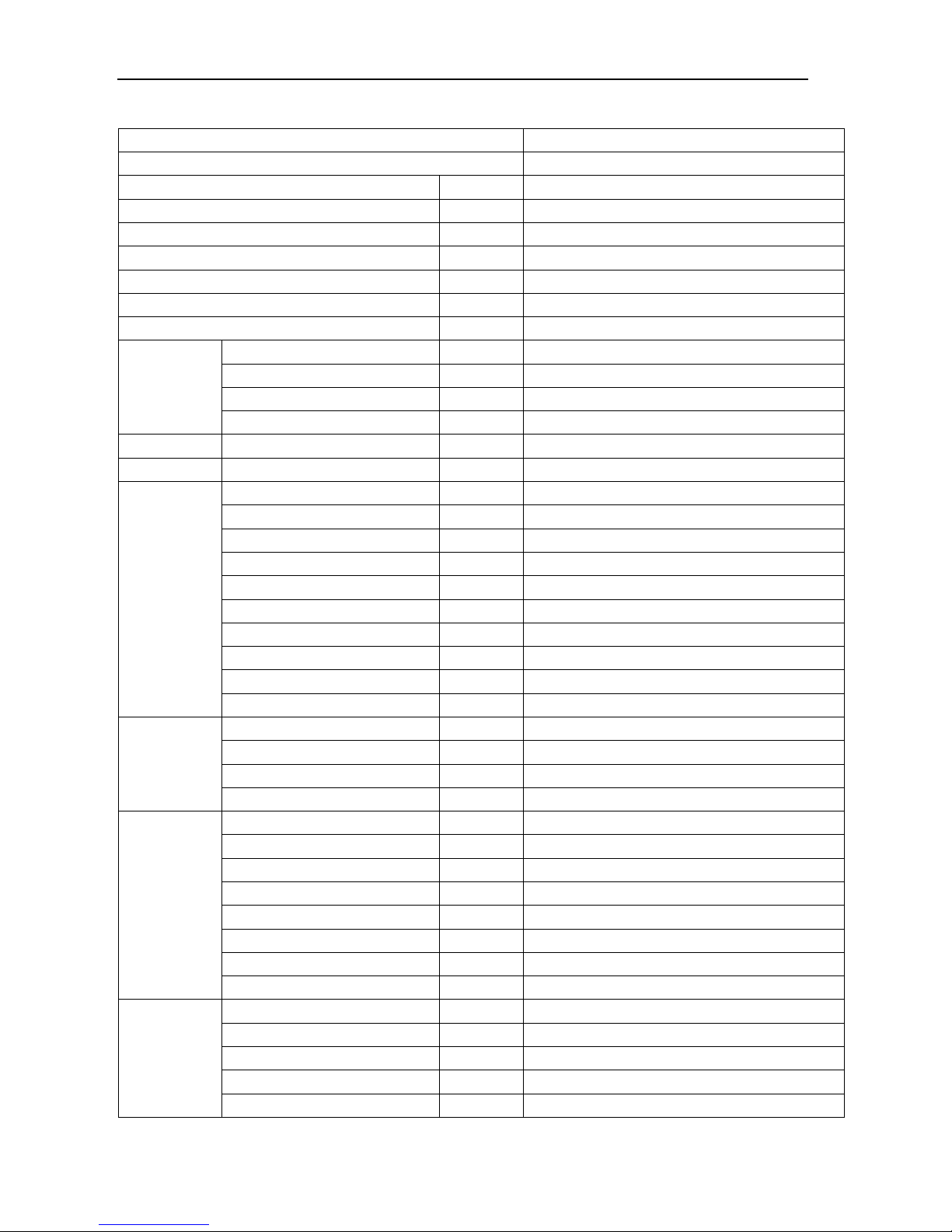
Indoor model
MAD030T1N1S1
Outdoor model (×Quantity)
MA0541 (×1)
Indoor operating ambient temperature range °C 0~40
Outdoor operating ambient temperature range °C -20~45, (-40~45, with low ambient temperature kit)
Altitude \
≤1000m (higher than 1000m, derating use)
Indoor Power supply V, Ph, Hz 380V~,3Ph,50Hz
Outdoor Power supply V, Ph, Hz 380V~,3Ph,50Hz
Whole unit Rated input W 18,500
Whole unit Rated current A 33
Cooling
Total capacity W 30,900
Sensible capacity W 27,810
Input W 11,300
EER W/W 2.73
E-heater Capacity W 6,000
Humidification Capacity kg/h 5
Compressor
Model \ ZP120KCE-TFD-522
Type \ Scroll
Qty. \ 1
Brand \ Copeland
Capacity W 29,200
Input W 9,200
Rated current (RLA) A 20
Locked rotor Amp (LRA) A 118
Thermal protector \ Internal
Refrigerant oil ml 3,253 (POE)
Indoor fan
Model (× quantity) \ Y2FD100L2-4 (×1)
Brand \ Huanqiu/Wolong
Input W 3,000
Speed r/min 1,420
Indoor coil
Number of rows \ 4
Tube pitch(a)×row pitch(b) mm 25.4×22
Fin spacing mm 1.8
Fin type \ Hydrophilic aluminum fin
Pipe size mm Ф9.52
Pipe type \ Inner grooved copper pipe
Coil(W×H) mm (726×686)+(726×686)
Number of circuits \ 9+9
Outdoor fan
Type \ FN type, AC axial fan
Motor Model (× Quantity) \ WZZ800-8 (×1)
Motor Brand \ Ziehl-Abegg
Motor Input W 1,100/760
Speed r/min 680/530
Outdoor coil No. of rows \ 3
Page 16
MCAC-PDSM-2013-04 Midea Precision AC Technical Manual-Down Delivery Series
15
Tube pitch(a)×row pitch(b) mm 25.4×22
Fin spacing mm 2.2
Fin type \ Hydrophilic aluminum fin
Pipe outside dia. and type mm
Ф9.52
Inner grooved copper pipe
Coil (W×D) mm 1447×1219
Number of circuits \ 12
Indoor air flow m3/h 8,825
Indoor external static pressure Pa 20
Indoor drain pipe I.D. mm Ф30
Indoor noise level dB(A) 67
Outdoor noise level dB(A) 65
Refrigerant
Type \ R410A
Recharged (After installation) g 12,000
Control \ Thermal expansion valve
Maximum refrigeration pipe pressure MPa 4.4
Refrigerant
pipe
Max. pipe length m 60
Max. difference in level (O.U. up) m 20
Max. difference in level (O.U.
down)
m 5
Connection
wire
Indoor power wire mm
2
3×10.0mm
2
(A,B,C)+2×6.0mm2(N,GND)
Outdoor power wire mm2 4×1.0mm2
Signal wire mm2 4×1.0mm2
Filter \ G4
Indoor unit
Net dimension (W×H×D) mm 895×1,971×870
Net weight kg 365/432
Outdoor unit
Net dimension (W×H×D) mm 1,660×1,290×690 (Without supporting bar)
Net weight kg 140/250
Notes:
1. The nominal cooling capacity is based on the following conditions. Indoor temperature: 24°CDB, 17°CWB;
Outdoor temperature: 35°CDB, pipe length is 10 meters.
2. The noise is measured in the semi suppression lab.
3. Specifications are subject to change without prior notice for product improvement.
Page 17

Midea Precision AC Technical Manual MCAC-PDSM-2013-01
16
Indoor model
MAD035T1N1S1
Outdoor model(×Quantity)
MA0601 (×1)
Indoor operating ambient temperature range °C 0~40
Outdoor operating ambient temperature range °C -20~45, (-40~45, with low ambient temperature kit)
Altitude \
≤1000m (higher than 1000m, derating use)
Indoor Power supply V, Ph, Hz 380V~,3Ph,50Hz
Outdoor Power supply V, Ph, Hz 380V~,3Ph,50Hz
Whole unit Rated input W 25,000
Whole unit Rated current A 46
Cooling
Total capacity W 34,000
Sensible capacity W 31,280
Input W 12,500
EER W/W 2.72
E-heater Capacity W 6,000
Humidification Capacity kg/h 5
Compressor
Model \ ZP137KCE-TFD-522
Type \ Scroll
Qty. \ 1
Brand \ Copeland
Capacity W 32,600
Input W 10,200
Rated current (RLA) A 20.7
Locked rotor Amp (LRA) A 118
Thermal protector \ Internal
Refrigerant oil ml 3,253 (POE)
Indoor fan
Model (× quantity) \ Y(2)100L2-4-3KW(YRZ) (×1)
Brand \ Huanqiu/Wolong
Input W 3,000
Speed r/min 1,420
Indoor coil
Number of rows \ 4
Tube pitch(a)×row pitch(b) mm 25.4×22
Fin spacing mm 1.8
Fin type \ Hydrophilic aluminum fin
Pipe size mm Ф9.52
Pipe type \ Inner grooved copper pipe
Coil(W×H) mm (1,210×660.4)+(1,210×660.4)
Number of circuits \ 13+13
Outdoor fan
Type \ Axial fan
Motor Model (× Quantity) \ FN080-ADK (×1)
Motor Brand \ Ziehl-Abegg
Motor Input W 1,100
Speed r/min 680
Page 18

MCAC-PDSM-2013-04 Midea Precision AC Technical Manual-Down Delivery Series
17
Outdoor coil
No. of rows \ 4
Tube pitch(a)×row pitch(b) mm 25.4×22
Fin spacing mm 2.2
Fin type \ Hydrophilic aluminum fin
Pipe outside dia. and type mm
Ф9.52
Inner grooved copper pipe
Coil (W×D) mm 1,448×1,219.2
Number of circuits \ 12
Indoor air flow m3/h 10,400
Indoor external static pressure Pa 20
Indoor drain pipe I.D. mm Ф30
Indoor noise level dB(A)
≤69
Outdoor noise level dB(A)
≤64
Refrigerant
Type \ R410A
Recharged (After installation) g 13,500
Control \ Thermal expansion valve
Maximum refrigeration pipe pressure MPa 4.4
Refrigerant
pipe
Max. pipe length m 60
Max. difference in level (O.U. up) m 20
Max. difference in level (O.U.
down)
m 5
Connection
wire
Indoor power wire mm2
3×10.0mm
2
(A,B,C)+2×6.0mm2(N,GND)
Outdoor power wire mm2 4×1.0mm2
Signal wire mm2 4×1.0mm2
Filter \ G4
Indoor unit
Net dimension (W×H×D) mm 1,400×1,971×870
Net weight kg 460
Outdoor unit
Net dimension (W×H×D) mm 1,660×1,290×690(No include supporting bar)
Net weight kg 150
Notes:
1. The nominal cooling capacity is based on the following conditions. Indoor temperature: 24°CDB, 17°CWB;
Outdoor temperature: 35°CDB, pipe length is 10 meters.
2. The noise is measured in the semi suppression lab.
3. Specifications are subject to change without prior notice for product improvement.
Page 19

Midea Precision AC Technical Manual MCAC-PDSM-2013-01
18
Indoor model
MAD040T2N1S1
Outdoor model(×Quantity)
MA0331 (×2)
Indoor operating ambient temperature range °C 0~40
Outdoor operating ambient temperature range °C -20~45, (-40~45, with low ambient temperature kit)
Altitude \
≤1000m (higher than 1000m, derating use)
Indoor Power supply V, Ph, Hz 380V~,3Ph,50Hz
Outdoor Power supply V, Ph, Hz 380V~,3Ph,50Hz
Whole unit Rated input W 32,000
Whole unit Rated current A 60
Cooling
Total capacity W 40,300
Sensible capacity W 38,290
Input W 15,400
EER W/W 2.62
E-heater Capacity W 9,000
Humidification Capacity kg/h 10
Compressor
Model \ ZP83KCE-TFD-522
Type \ Scroll
Qty. \ 2
Brand \ Copeland
Capacity W 20,000
Input W 6,400
Rated current (RLA) A 13.6
Locked rotor Amp (LRA) A 101
Thermal protector \ Internal
Refrigerant oil ml 1,774 (POE)
Indoor fan
Model (× quantity) \ Y(2)100L1-4-2.2KW(YRZ) (×2)
Brand \ Huanqiu/Wolong
Input W 2,200
Speed r/min 1,420
Indoor coil
Number of rows \ 4
Tube pitch(a)×row pitch(b) mm 25.4×22
Fin spacing mm 1.8
Fin type \ Hydrophilic aluminum fin
Pipe size mm Ф9.52
Pipe type \ Inner grooved copper pipe
Coil(W×H) mm (1,590×685.8)+(1,590×685.8)
Number of circuits \ 18+18
Outdoor fan
(Single
outdoor unit)
Type \ Axial fan
Motor Model (× Quantity) \ FN071-SDK (×1)
Motor Brand \ Ziehl-Abegg
Motor Input W 940
Speed r/min 900
Page 20

MCAC-PDSM-2013-04 Midea Precision AC Technical Manual-Down Delivery Series
19
Outdoor coil
(Single
outdoor unit)
No. of rows \ 3
Tube pitch(a)×row pitch(b) mm 25.4×22
Fin spacing mm 2.2
Fin type \ Hydrophilic aluminum fin
Pipe outside dia. and type mm
Ф9.52
Inner grooved copper pipe
Coil (W×D) mm 1,250×914.4
Number of circuits \ 6
Indoor air flow m3/h 11,980
Indoor external static pressure Pa 20
Indoor drain pipe I.D. mm Ф30
Indoor noise level dB(A)
≤69
Outdoor noise level dB(A)
≤64
Refrigerant
Type \ R410A
Recharged (After installation) g 8,500×2
Control \ Thermostatic expansion valve
Maximum refrigeration pipe pressure MPa 4.4
Refrigerant
pipe
Max. pipe length m 60
Max. difference in level (O.U. up) m 20
Max. difference in level (O.U.
down)
m 5
Connection
wire
Indoor power wire mm2
3×10.0mm
2
(A,B,C)+2×6.0mm2(N,GND)
Outdoor power wire mm2 (4×1.0mm2)+(4×1.0mm2)
Signal wire mm2 (4×1.0mm2)+ (4×1.0mm2)
Filter \ G4
Indoor unit
Net dimension (W×H×D) mm 1,790×1,971×870
Net weight kg 563
Outdoor unit
(Single)
Net dimension (W×H×D) mm 1,470×988×690(No include supporting bar)
Net weight kg 105
Notes:
1. The nominal cooling capacity is based on the following conditions. Indoor temperature: 24°CDB, 17°CWB;
Outdoor temperature: 35°CDB, pipe length is 10 meters.
2. The noise is measured in the semi suppression lab.
3. Specifications are subject to change without prior notice for product improvement.
Page 21

Midea Precision AC Technical Manual MCAC-PDSM-2013-01
20
Indoor model
MAD045T1N1S1
Outdoor model(×Quantity)
MA0752 (×1)
Indoor operating ambient temperature range °C 0~40
Outdoor operating ambient temperature range °C -20~45, (-40~45, with low ambient temperature kit)
Altitude \
≤1000m (higher than 1000m, derating use)
Indoor Power supply V, Ph, Hz 380V~,3Ph,50Hz
Outdoor Power supply V, Ph, Hz 380V~,3Ph,50Hz
Whole unit Rated input W 33,000
Whole unit Rated current A 62
Cooling
Total capacity W 44,900
Sensible capacity W 41,310
Input W 16,900
EER W/W 2.66
E-heater Capacity W 9,000
Humidification Capacity kg/h 10
Compressor
Model \ ZP182KCE-TFD-522
Type \ Scroll
Qty. \ 1
Brand \ Copeland
Capacity W 44,000
Input W 13,500
Rated current (RLA) A 29.3
Locked rotor Amp (LRA) A 174
Thermal protector \ Internal
Refrigerant oil ml 3,253 (POE)
Indoor fan
Model (× quantity) \ Y(2)100L1-4-2.2KW(YRZ) (×2)
Brand \ Huanqiu/Wolong
Input W 2,200
Speed r/min 1,420
Indoor coil
Number of rows \ 4
Tube pitch(a)×row pitch(b) mm 25.4×22
Fin spacing mm 1.8
Fin type \ Hydrophilic aluminum fin
Pipe size mm Ф9.52
Pipe type \ Inner grooved copper pipe
Coil(W×H) mm (1,590×685.8)+(1,590×685.8)
Number of circuits \ 18+18
Outdoor fan
Type \ Axial fan
Motor Model (× Quantity) \ FN071-SDK (×2)
Motor Brand \ Ziehl-Abegg
Motor Input W 940
Speed r/min 900
Page 22

MCAC-PDSM-2013-04 Midea Precision AC Technical Manual-Down Delivery Series
21
Outdoor coil
No. of rows \ 3
Tube pitch(a)×row pitch(b) mm 25.4×22
Fin spacing mm 2.2
Fin type \ Hydrophilic aluminum fin
Pipe outside dia. and type mm
Ф9.52
Inner grooved copper pipe
Coil (W×D) mm 1,750×1,219.2
Number of circuits \ 18
Indoor air flow m3/h 13,030
Indoor external static pressure Pa 20
Indoor drain pipe I.D. mm Ф30
Indoor noise level dB(A)
≤69
Outdoor noise level dB(A)
≤64
Refrigerant
Type \ R410A
Recharged (After installation) g 17,000
Control \ Thermostatic expansion valve
Maximum refrigeration pipe pressure MPa 4.4
Refrigerant
pipe
Max. pipe length m 60
Max. difference in level (O.U. up) m 20
Max. difference in level (O.U.
down)
m 5
Connection
wire
Indoor power wire mm2
3×10.0mm
2
(A,B,C)+2×6.0mm2(N,GND)
Outdoor power wire mm2 4×1.0mm2
Signal wire mm2 4×1.0mm2
Filter \ G4
Indoor unit
Net dimension (W×H×D) mm 1,790×1,971×870
Net weight kg 560
Outdoor unit
Net dimension (W×H×D) mm 1,980×1,290×690(No include supporting bar)
Net weight kg 170
Notes:
1. The nominal cooling capacity is based on the following conditions. Indoor temperature: 24°CDB, 17°CWB;
Outdoor temperature: 35°CDB, pipe length is 10 meters.
2. The noise is measured in the semi suppression lab.
3. Specifications are subject to change without prior notice for product improvement.
Page 23
Midea Precision AC Technical Manual MCAC-PDSM-2013-01
22
Indoor model
MAD050T2N1S1
Outdoor model(×Quantity)
MA0431 (×2)
Indoor operating ambient temperature range °C 0~40
Outdoor operating ambient temperature range °C -20~45, (-40~45, with low ambient temperature kit)
Altitude \
≤1000m (higher than 1000m, derating use)
Indoor Power supply V, Ph, Hz 380V~,3Ph,50Hz
Outdoor Power supply V, Ph, Hz 380V~,3Ph,50Hz
Whole unit Rated input W 36,000
Whole unit Rated current A 65
Cooling
Total capacity W 49,700
Sensible capacity W 45,230
Input W 19,100
EER W/W 2.6
E-heater Capacity W 9,000
Humidification Capacity kg/h 10
Compressor
Model \ ZP103KCE-TFD-522
Type \ Scroll
Qty. \ 2
Brand \ Copeland
Capacity W 25,200
Input W 7,800
Rated current (RLA) A 18.6
Locked rotor Amp (LRA) A 111
Thermal protector \ Internal
Refrigerant oil ml 3,253 (POE)
Indoor fan
Model (× quantity) \ Y(2)100L2-4-3KW(YRZ) (×2)
Brand \ Huanqiu/Wolong
Input W 3,000
Speed r/min 1,420
Indoor coil
Number of rows \ 4
Tube pitch(a)×row pitch(b) mm 25.4×22
Fin spacing mm 1.8
Fin type \ Hydrophilic aluminum fin
Pipe size mm Ф9.52
Pipe type \ Inner grooved copper pipe
Coil(W×H) mm (1,590×685.8)+(1,590×685.8)
Number of circuits \ 18+18
Outdoor fan
(Single
outdoor unit)
Type \ Axial fan
Motor Model (× Quantity) \ FN080-ADK (×1)
Motor Brand \ Ziehl-Abegg
Motor Input W 1,100
Speed r/min 680
Page 24

MCAC-PDSM-2013-04 Midea Precision AC Technical Manual-Down Delivery Series
23
Outdoor coil
(Single
outdoor unit)
No. of rows \ 3
Tube pitch(a)×row pitch(b) mm 25.4×22
Fin spacing mm 2.2
Fin type \ Hydrophilic aluminum fin
Pipe outside dia. and type mm
Ф9.52
Inner grooved copper pipe
Coil (W×D) mm 1,250×914.4
Number of circuits \ 6
Indoor air flow m3/h 14,500
Indoor external static pressure Pa 20
Indoor drain pipe I.D. mm Ф30
Indoor noise level dB(A)
≤69
Outdoor noise level dB(A)
≤64
Refrigerant
Type \ R410A
Recharged (After installation) g 9,500×2
Control \ Thermostatic expansion valve
Maximum refrigeration pipe pressure MPa 4.4
Refrigerant
pipe
Max. pipe length m 60
Max. difference in level (O.U. up) m 20
Max. difference in level (O.U.
down)
m 5
Connection
wire
Indoor power wire mm2
3×10.0mm
2
(A,B,C)+2×6.0mm2(N,GND)
Outdoor power wire mm2 (4×1.0mm2)+ (4×1.0mm2)
Signal wire mm2 (4×1.0mm2)+ (4×1.0mm2)
Filter \ G4
Indoor unit
Net dimension (W×H×D) mm 1,790×1,971×870
Net weight kg 665
Outdoor unit
(Single)
Net dimension (W×H×D) mm 1,470×988×690(No include supporting bar)
Net weight kg 105
Notes:
1. The nominal cooling capacity is based on the following conditions. Indoor temperature: 24°CDB, 17°CWB;
Outdoor temperature: 35°CDB, pipe length is 10 meters.
2. The noise is measured in the semi suppression lab.
3. Specifications are subject to change without prior notice for product improvement.
Page 25

Midea Precision AC Technical Manual MCAC-PDSM-2013-01
24
Indoor model
MAD060T2N1S1
Outdoor model(×Quantity)
MA0541 (×2)
Indoor operating ambient temperature range °C 0~40
Outdoor operating ambient temperature range °C -20~45, (-40~45, with low ambient temperature kit)
Altitude \
≤1000m (higher than 1000m, derating use)
Indoor Power supply V, Ph, Hz 380V~,3Ph,50Hz
Outdoor Power supply V, Ph, Hz 380V~,3Ph,50Hz
Whole unit Rated input W 39,000
Whole unit Rated current A 70
Cooling
Total capacity W 59,100
Sensible capacity W 53,190
Input W 22,600
EER W/W 2.62
E-heater Capacity W 9,000
Humidification Capacity kg/h 10
Compressor
Model \ ZP120KCE-TFD-522
Type \ Scroll
Qty. \ 2
Brand \ Copeland
Capacity W 29,200
Input W 9,200
Rated current (RLA) A 20
Locked rotor Amp (LRA) A 118
Thermal protector \ Internal
Refrigerant oil ml 3,253 (POE)
Indoor fan
Model (× quantity) \ Y(2)100L2-4-3KW(YRZ) (×2)
Brand \ Huanqiu/Wolong
Input W 3,000
Speed r/min 1,420
Indoor coil
Number of rows \ 4
Tube pitch(a)×row pitch(b) mm 25.4×22
Fin spacing mm 1.8
Fin type \ Hydrophilic aluminum fin
Pipe size mm Ф9.52
Pipe type \ Inner grooved copper pipe
Coil(W×H) mm (1,590×685.8)+(1,590×685.8)
Number of circuits \ 18+18
Outdoor fan
(Single
outdoor unit)
Type \ Axial fan
Motor Model (× Quantity) \ FN080-ADK (×1)
Motor Brand \ Ziehl-Abegg
Motor Input W 1,100
Speed r/min 680
Page 26
MCAC-PDSM-2013-04 Midea Precision AC Technical Manual-Down Delivery Series
25
Outdoor coil
(Single
outdoor unit)
No. of rows \ 3
Tube pitch(a)×row pitch(b) mm 25.4×22
Fin spacing mm 2.2
Fin type \ Hydrophilic aluminum fin
Pipe outside dia. and type mm
Ф9.52
Inner grooved copper pipe
Coil (W×D) mm 1447×1219
Number of circuits \ 12
Indoor air flow m3/h 17,000
Indoor external static pressure Pa 20
Indoor drain pipe I.D. mm Ф30
Indoor noise level dB(A)
≤72
Outdoor noise level dB(A)
≤66
Refrigerant
Type \ R410A
Recharged (After installation) g 11,500×2
Control \ Thermostatic expansion valve
Maximum refrigeration pipe pressure MPa 4.4
Refrigerant
pipe
Max. pipe length m 60
Max. difference in level (O.U. up) m 20
Max. difference in level (O.U.
down)
m 5
Connection
wire
Indoor power wire mm2
3×10.0mm
2
(A,B,C)+2×6.0mm2(N,GND)
Outdoor power wire mm2 (4×1.0mm2)+ (4×1.0mm2)
Signal wire mm2 (4×1.0mm2)+ (4×1.0mm2)
Filter \ G4
Indoor unit
Net dimension (W×H×D) mm 1,790×1,971×870
Net weight kg 680
Outdoor unit
(Single)
Net dimension (W×H×D) mm 1,660×1,290×690(No include supporting bar)
Net weight kg 140
Notes:
1. The nominal cooling capacity is based on the following conditions. Indoor temperature: 24°CDB, 17°CWB;
Outdoor temperature: 35°CDB, pipe length is 10 meters.
2. The noise is measured in the semi suppression lab.
3. Specifications are subject to change without prior notice for product improvement.
Page 27

Midea Precision AC Technical Manual MCAC-PDSM-2013-01
26
Indoor model MAD070T2N1S1
Outdoor model(×Quantity) MA0601 (×2)
Indoor operating ambient temperature range °C 0~40
Outdoor operating ambient temperature range °C -20~45, (-40~45, with low ambient temperature kit)
Altitude \
≤1000m (higher than 1000m, derating use)
Indoor Power supply V, Ph, Hz 380V~,3Ph,50Hz
Outdoor Power supply V, Ph, Hz 380V~,3Ph,50Hz
Whole unit Rated input W 42,000
Whole unit Rated current A 74
Cooling
Total capacity W 71,100
Sensible capacity W 67,550
Input W 26,800
EER W/W 2.65
E-heater Capacity W 12,000
Humidification Capacity kg/h 10
Compressor
Model \ ZP137KCE-TFD-522
Type \ Scroll
Qty. \ 2
Brand \ Copeland
Capacity W 32,600
Input W 10,200
Rated current (RLA) A 20.7
Locked rotor Amp (LRA) A 118
Thermal protector \ Internal
Refrigerant oil ml 3,253 (POE)
Indoor fan
Model (× quantity) \ Y(2)100L1-4-2.2KW(YRZ) (×3)
Brand \ Huanqiu/Wolong
Input W 2,200
Speed r/min 1,420
Indoor coil
Number of rows \ 4
Tube pitch(a)×row pitch(b) mm 25.4×22
Fin spacing mm 1.8
Fin type \ Hydrophilic aluminum fin
Pipe size mm Ф9.52
Pipe type \ Inner grooved copper pipe
Coil(W×H) mm (2,453×660.4)+(2,453×660.4)
Number of circuits \ 26+26
Outdoor fan
(Single
outdoor unit)
Type \ Axial fan
Motor Model (× Quantity) \ FN080-ADK (×1)
Motor Brand \ Ziehl-Abegg
Motor Input W 1,100
Speed r/min 680
Page 28

MCAC-PDSM-2013-04 Midea Precision AC Technical Manual-Down Delivery Series
27
Outdoor coil
(Single
outdoor unit)
No. of rows \ 4
Tube pitch(a)×row pitch(b) mm 25.4×22
Fin spacing mm 2.2
Fin type \ Hydrophilic aluminum fin
Pipe outside dia. and type mm
Ф9.52
Inner grooved copper pipe
Coil (W×D) mm 1,448×1,219.2
Number of circuits \ 12
Indoor air flow m3/h 20,800
Indoor external static pressure Pa 20
Indoor drain pipe I.D. mm Ф30
Indoor noise level dB(A)
≤72
Outdoor noise level dB(A)
≤66
Refrigerant
Type \ R410A
Recharged (After installation) g 13,000×2
Control \ Thermostatic expansion valve
Maximum refrigeration pipe pressure MPa 4.4
Refrigerant
pipe
Max. pipe length m 60
Max. difference in level (O.U. up) m 20
Max. difference in level (O.U.
down)
m 5
Connection
wire
Indoor power wire mm2
3×10.0mm
2
(A,B,C)+2×6.0mm2(N,GND)
Outdoor power wire mm2 (4×1.0mm2)+ (4×1.0mm2)
Signal wire mm2 (4×1.0mm2)+ (4×1.0mm2)
Filter \ G4
Indoor unit
Net dimension (W×H×D) mm 2,685×1,971×870
Net weight kg 910
Outdoor unit
(Single)
Net dimension (W×H×D) mm 1,660×1,290×690(No include supporting bar)
Net weight kg 150
Notes:
1. The nominal cooling capacity is based on the following conditions. Indoor temperature: 24°CDB, 17°CWB;
Outdoor temperature: 35°CDB, pipe length is 10 meters.
2. The noise is measured in the semi suppression lab.
3. Specifications are subject to change without prior notice for product improvement.
Page 29

Midea Precision AC Technical Manual MCAC-PDSM-2013-01
28
Indoor model
MAD080T2N1S1
Outdoor model(×Quantity)
MA0752 (×2)
Indoor operating ambient temperature range °C 0~40
Outdoor operating ambient temperature range °C -20~45, (-40~45, with low ambient temperature kit)
Altitude \
≤1000m (higher than 1000m, derating use)
Indoor Power supply V, Ph, Hz 380V~,3Ph,50Hz
Outdoor Power supply V, Ph, Hz 380V~,3Ph,50Hz
Whole unit Rated input W 48,000
Whole unit Rated current A 91
Cooling
Total capacity W 81,100
Sensible capacity W 73,800
Input W 30,700
EER W/W 2.64
E-heater Capacity W 12,000
Humidification Capacity kg/h 10
Compressor
Model \ ZP154KCE-TFD-522
Type \ Scroll
Qty. \ 2
Brand \ Copeland
Capacity W 37,300
Input W 11,600
Rated current (RLA) A 25
Locked rotor Amp (LRA) A 140
Thermal protector \ Internal
Refrigerant oil ml 3,253 (POE)
Indoor fan
Model (× quantity) \ Y(2)100L1-4-2.2KW(YRZ) (×3)
Brand \ Huanqiu/Wolong
Input W 2,200
Speed r/min 1,420
Indoor coil
Number of rows \ 4
Tube pitch(a)×row pitch(b) mm 25.4×22
Fin spacing mm 1.8
Fin type \ Hydrophilic aluminum fin
Pipe size mm Ф9.52
Pipe type \ Inner grooved copper pipe
Coil(W×H) mm (2,453×660.4)+(2,453×660.4)
Number of circuits \ 26+26
Outdoor fan
(Single
outdoor unit)
Type \ Axial fan
Motor Model (× Quantity) \ FN071-SDK (×2)
Motor Brand \ Ziehl-Abegg
Motor Input W 940
Speed r/min 900
Page 30

MCAC-PDSM-2013-04 Midea Precision AC Technical Manual-Down Delivery Series
29
Outdoor coil
(Single
outdoor unit)
No. of rows \ 3
Tube pitch(a)×row pitch(b) mm 25.4×22
Fin spacing mm 2.2
Fin type \ Hydrophilic aluminum fin
Pipe outside dia. and type mm
Ф9.52
Inner grooved copper pipe
Coil (W×D) mm 1,750×1,219.2
Number of circuits \ 18
Indoor air flow m3/h 23,300
Indoor external static pressure Pa 20
Indoor drain pipe I.D. mm Ф30
Indoor noise level dB(A)
≤72
Outdoor noise level dB(A)
≤66
Refrigerant
Type \ R410A
Recharged (After installation) g 17,000×2
Control \ Thermostatic expansion valve
Maximum refrigeration pipe pressure MPa 4.4
Refrigerant
pipe
Max. pipe length m 60
Max. difference in level (O.U. up) m 20
Max. difference in level (O.U.
down)
m 5
Connection
wire
Indoor power wire mm2
3×10.0mm
2
(A,B,C)+2×6.0mm2(N,GND)
Outdoor power wire mm2 (4×1.0mm2)+ (4×1.0mm2)
Signal wire mm2 (4×1.0mm2)+ (4×1.0mm2)
Filter \ G4
Indoor unit
Net dimension (W×H×D) mm 2,685×1,971×870
Net weight kg 920
Outdoor unit
(Single)
Net dimension (W×H×D) mm 1,980×1,290×690(No include supporting bar)
Net weight kg 170
Notes:
1. The nominal cooling capacity is based on the following conditions. Indoor temperature: 24°CDB, 17°CWB;
Outdoor temperature: 35°CDB, pipe length is 10 meters.
2. The noise is measured in the semi suppression lab.
3. Specifications are subject to change without prior notice for product improvement.
Page 31

Midea Precision AC Technical Manual MCAC-PDSM-2013-01
30
Indoor model
MAD090T2N1S1
Outdoor model(×Quantity)
MA0982 (×2)
Indoor operating ambient temperature range °C 0~40
Outdoor operating ambient temperature range °C -20~45, (-40~45, with low ambient temperature kit)
Altitude \
≤1000m (higher than 1000m, derating use)
Indoor Power supply V, Ph, Hz 380V~,3Ph,50Hz
Outdoor Power supply V, Ph, Hz 380V~,3Ph,50Hz
Whole unit Rated input W 55,000
Whole unit Rated current A 98
Cooling
Total capacity W 90,100
Sensible capacity W 81,090
Input W 34,300
EER W/W 2.63
E-heater Capacity W 12,000
Humidification Capacity kg/h 10
Compressor
Model \ ZP182KCE-TFD-522
Type \ Scroll
Qty. \ 2
Brand \ Copeland
Capacity W 44,000
Input W 13,500
Rated current (RLA) A 29.3
Locked rotor Amp (LRA) A 174
Thermal protector \ Internal
Refrigerant oil ml 3,253 (POE)
Indoor fan
Model (× quantity) \ Y(2)100L2-4-3KW(YRZ) (×3)
Brand \ Huanqiu/Wolong
Input W 3,000
Speed r/min 1,420
Indoor coil
Number of rows \ 4
Tube pitch(a)×row pitch(b) mm 25.4×22
Fin spacing mm 1.8
Fin type \ Hydrophilic aluminum fin
Pipe size mm Ф9.52
Pipe type \ Inner grooved copper pipe
Coil(W×H) mm (2,453×660.4)+(2,453×660.4)
Number of circuits \ 26+26
Outdoor fan
(Single
outdoor unit)
Type \ Axial fan
Motor Model (× Quantity) \ FN080-ADK (×2)
Motor Brand \ Ziehl-Abegg
Motor Input W 1,100
Speed r/min 680
Page 32

MCAC-PDSM-2013-04 Midea Precision AC Technical Manual-Down Delivery Series
31
Outdoor coil
(Single
outdoor unit)
No. of rows \ 3
Tube pitch(a)×row pitch(b) mm 25.4×22
Fin spacing mm 2.2
Fin type \ Hydrophilic aluminum fin
Pipe outside dia. and type mm
Ф9.52
Inner grooved copper pipe
Coil (W×D) mm 2,250×1,219.2
Number of circuits \ 18
Indoor air flow m3/h 24,800
Indoor external static pressure Pa 20
Indoor drain pipe I.D. mm Ф30
Indoor noise level dB(A)
≤72
Outdoor noise level dB(A)
≤66
Refrigerant
Type \ R410A
Recharged (After installation) g 17,000×2
Control \ Thermostatic expansion valve
Maximum refrigeration pipe pressure MPa 4.4
Refrigerant
pipe
Max. pipe length m 60
Max. difference in level (O.U. up) m 20
Max. difference in level (O.U.
down)
m 5
Connection
wire
Indoor power wire mm2
3×10.0mm
2
(A,B,C)+2×6.0mm2(N,GND)
Outdoor power wire mm2 (4×1.0mm2)+ (4×1.0mm2)
Signal wire mm2 (4×1.0mm2)+ (4×1.0mm2)
Filter \ G4
Indoor unit
Net dimension (W×H×D) mm 2,685×1,971×870
Net weight kg 920
Outdoor unit
(Single)
Net dimension (W×H×D) mm 2,480×1,290×690(No include supporting bar)
Net weight kg 220
Notes:
1. The nominal cooling capacity is based on the following conditions. Indoor temperature: 24°CDB, 17°CWB;
Outdoor temperature: 35°CDB, pipe length is 10 meters.
2. The noise is measured in the semi suppression lab.
3. Specifications are subject to change without prior notice for product improvement.
Page 33

Midea Precisi
32
2.4 Dime
n
Indoo
r
on AC Techni
c
sion (Uni
unit: MAD
0
al Manual
t: mm)
20T1N1S1
, MAD025
T
1N1S1, M
A
D030T1N1
S
M
1
MCAC-PDSM-2013-01
Page 34

MCAC-PDS
M
Indoo
r
-2013-04
unit: MAD
0
35T1N1S1
Mide
a
View of o
p
Precision A
C
ened doo
r
Technical M
a
nual-Down Delivery Series
3
3
Page 35

Midea Precisi
34
Indoo
r
Indoo
r
on AC Techni
c
unit: MAD
0
unit: MAD
0
al Manual
40T2N1S1
70T2N1S1
, MAD045
T
, MAD080
T
1N1S1, M
A
2N1S1, M
A
D050T2N1
S
D090T2N1
S
M
1, MAD06
0
1
MCAC-PDS
M
T2N1S1
-2013-01
Page 36

MCAC-PDS
M
Outdo
o
Outdo
o
-2013-04
r unit: M
A
r unit: M
A
0331, MA0
4
0752, MA0
9
Mod
e
MA03
3
MA04
3
MA05
4
MA06
0
MA07
5
MA09
8
31, MA05
4
82
l
L
1
14
7
1
1
16
6
1
2 19
8
2 24
8
Mide
a
1, MA0601
0
9
0
1
0
0
Precision A
C
H
88
290
Technical M
a
W
690
nual-Down Delivery Series
3
5
Page 37

Midea Precisi
36
2.5 Servi
c
Indoo
r
Outdo
o
Outdo
o
on AC Techni
c
e space
unit (Unit:
r unit wit
h
r unit wit
h
al Manual
mm)
horizontal
vertical in
s
installatio
n
tallation (
U
(Unit: mm
nit: mm)
) MMCAC-PDS
M
-2013-01
Page 38

M
3
2
idea Precision AC
7
.6 Wiring dia
g
E-box view
o
Technical Manual-
D
ram
f indoor unit
own Delivery Series MCAC-RTSM-2013-04
Page 39

M
3
idea Precision AC
8
Indoor unit
w
Available for
M
Indoor unit
w
Available for
M
Technical Manual
ith single sys
t
AD020T1N1S1,
M
ith dual-syste
m
AD040T2N1S1,
M
em- Controllin
g
AD025T1N1S1, M
A
- Controlling
c
AD050T2N1S1, M
A
connection a
m
A
D030T1N1S1, an
onnection am
p
A
D060T2N1S1, M
A
plification figu
r
d MAD035T1N1S,
lification figur
e
D070T2N1S1, M
A
e:
MAD045T1N1S1
:
D080T2N1S1, and
MAD090T2N1S1
MCAC-PDSM-2013-01
Page 40

Midea Precisi
39
Outdo
o
Outdo
o
on AC Techni
c
r unit- M
A
r unit- M
A
al Manual-D
o
0331, MA0
4
0752, MA0
9
wn Delivery
S
31, MA05
4
82
eries
1, MA0601
MCAC-R
T
SM-2013-04
Page 41

Midea Precisi
40
3. Insta
l
Th
eout
Be
f
se
r
pip
Ins
Th
e
Notes:
——: Pi
------: T
h
※ : Fo
r
(D
o
+ : W
co
on AC Techni
c
lation
indoor uni
t
door unit is
ore the ins
t
vice, and c
o
eline laying
,
tallation wo
r
whole sys
t
pelines prov
i
e site-laying
system nor
m
ne by sit)
hen the equi
v
mponents. (
T
al Manual
must be in
installed on
allation, co
n
nfirm whet
h
wiring and
k must stri
c
em layout
d
ded by man
u
pipeline (D
o
al operatio
n
altent lengt
h
hese option
a
stalled on t
h
the ground
firm wheth
e
er the buil
d
ventilation
p
tly follow th
iagram:
facturer
ne by techni
c
and mainte
n
of the pipe
l compone
n
e ground o
f
of the outd
o
r the install
ings need t
o
ipe.
e design dr
a
ians)
nance conve
exceeds 30
m
ts need to b
e
the device
ors or oth
e
ation envir
o
be config
u
wing.
nience, the
c
eters, then
purchased
M
room or co
m
r rooms.
ment meet
t
red with th
e
omponents
a
t should be
e
y another o
MCAC-PDS
M
puter roo
m
he require
m
constructi
o
re suppose
d
qquipped
w
rder).
-2013-01
. And the
ents of
n work of
to be used.
ith these
Page 42

MCAC-PDS
M
W
h
of
re
v
co
T
h
-2013-04
en the con
d
the conden
erse bend,
pper pipe o
f
e installatio
enser is hi
g
ser, to avoi
d
it must ens
u
condenser
n diagram,
w
her than c
o
liquid refri
re that the
hen the in
d
Mide
a
mpressor, i
gerant bac
k
top elbow
p
oor unit is
h
Precision A
C
nstall rever
s
flow when
t
ipe of the r
e
igher than
Technical M
a
e bend on
t
he units st
o
verse bend
outdoor uni
t
nual-Down D
he inlet an
d
ps. When
i
higher tha
n
t
.
elivery Series
4
1
outlet pipe
s
nstalling th
e
the top ro
w
Page 43

Midea Precisi
42
3.1 Stora
g
St
oAmAmSto
3.2 Indoo
r
Ta
w
o
M
othe
In
onor
Co
m
o
co
n
Ou
de
h
inh
wi
n
Be
cdam
ind
To
uni
Do
ref
r
on AC Techni
c
e enviro
n
Items
rage enviro
n
bient humid
i
bient tempe
r
rage time
installat
i
ke down th
e
oden case.
ve the bac
k
bolts with
w
rder to ens
mally, it sh
o
mputer roo
m
isture-proo
f
crete wall
a
tdoor air en
t
umidifyting
aled quanti
t
dows shoul
ause the a
age of oth
e
oor unit, an
d
ensure the
n
t installatio
n
not install t
h
igeration c
y
al Manual
ment
ment Ind
ty 5%
ature Ind
To
t
mo
on
packaging
plate, and
rench.
ure that the
uld do the
m
should ha
layer of cei
nd ground
m
er into the
r
load, so it i
s
y should re
m
d be fully e
n
ir condition
e
r precision
the install
a
ormal ope
r
site.
e indoor u
n
cle, and th
e
oor, clean.
~85% RH (
N
oor unit: -20
°
al time of tr
nths. If exce
case, acco
r
the unit ba
s
environme
n
oisture-pr
o
v
e good th
e
ling and wa
l
ust be mo
oom may i
n
necessar
y
ain below
closed typ
e
r will produ
c
equipment
s
tion scene
ation of ind
o
it in the na
r
n leads to
a
R
o condens
a
°C~54°C; Ou
t
ansportatio
n
ed 6 month
s
rding to the
e was fixe
d
t control s
y
of and hea
t
rmal insula
t
ll must use
p
isture-proof
crease the
to minimiz
e
5%of whol
e
, and apert
ce the cond
nearby, th
e
of air condi
t
or unit, it s
row space,
short circu
equiremen
t
tion)
door unit:
-4
0
and storag
, it need to
r
package di
a
in the bott
o
stem in the
preservati
o
ion and se
a
olyethylen
e
.
system coo
outdoor ai
indoor air
c
ure are as
s
ensate and
re is not th
ioner must
hould choo
s
or it would
b
it of returni
n
M
s
°C~70°C.
time shou
e-calibrate t
h
gram to re
m
m wood tra
y
air conditio
n
n work.
led moistur
e
film mater
i
ling, heatin
g
r enter into
t
irculation a
m
mall as pos
water leak
a
precision
e
be provided
e capaciou
s
lock the ai
r
g air and ai
MCAC-PDS
M
ld not exce
e
e capacity.
ove the p
a
y with M8 b
ing room
w
-proof lay
e
ials. The pa
, humidifyi
n
he room.
O
ount, all t
h
sible.
ge may ca
u
equipment
s
the draina
g
space as
t
flow, and
s
r noise.
-2013-01
d 6
ckaging
lts, remov
e
orks
r, the
inting of
g and
utdoor air
e doors an
d
se the
near the
e pipelines
he indoor
horten the
.
Page 44

MCAC-PDS
M
Do
Do
th
e
Do
Ac
c
ins
t
Pl
a
De
t
ins
t
Us
e
All
ch
o
Si
n
Du
a
-2013-04
not fix the i
not make s
unbalance
d
not install
o
ording to t
h
t
alled.
ce rubber d
ermine the
t
all the inst
a
bolts, cus
h
outside pla
t
osing insta
gle-door u
n
l-door unit
ndoor unit i
n
everal indo
o
competiti
o
ther equip
m
e bottom in
amping ma
t
installation
llation bas
e
ion, flat m
a
es of the u
n
llation angl
e
it installatio
n
installation
the sunke
n
r units to b
e
n operation
ents on its
stallation si
z
s on the to
p
osition, an
d
at the sele
c
t and nuts t
it should n
o
s and fixed
basing si
z
basing size
:
Mide
a
place or a
t
huddled t
o
.
upper part,
e of the in
d
of the inst
a
according
ted positio
n
o fix the air
t allow bea
r
holes.
e: (Unit: m
m
: (Unit: mm)
Precision A
C
the end of
gether, to
a
convenient
oor unit, th
e
llation bas
e
to the site
c
.
conditioner
ing weight,
)
Technical M
a
the long an
d
void crossi
n
for its norm
a
installatio
n
and steel
p
ondition an
d
on the bas
e
it must be
c
nual-Down D
narrow ro
o
g the air a
n
l maintena
base shou
late botto
m
user’s req
.
onsidered
w
elivery Series
4
3
m.
d producin
g
nce.
ld be
.
uierments t
o
hen
Page 45

Midea Precisi
44
Th
r
I
Steel plate
Angle iron (S
t
Anti-shock
rubber pa
d
Fixing hole fo
H
Notes:
The in
To
re
d
fa
s
Fi
r
fa
s
on AC Techni
c
ee-door un
i
tem
eel channel)
Top
Botto
m
r expansion b
stallation ba
s
prevent de
f
uction mat
e
teners and
st dismantl
e
tening torq
u
al Manual
t installatio
n
Spec
100
40×4
0
Th
Thi
c
olt
e should be
ormation a
n
rials on th
e
vibration re
d three L s
h
e: 12±1N.
m
basing siz
e
ification (m
m
×100×(5~6.5)
×3 (50×37×4
.
ickness: 3~5
kness: 10~1
2
300
strong to su
d damage
d
key place
s
duction ma
t
ape fixed
m
.
: (Unit: m
m
)
5)
Rubbe
r
rubber
o
Install
a
This is
o
needs
o
pport the in
d
uring tran
s
when the
u
erials befor
e
etal plates
)
materical ca
n
r rubber gas
k
s user requir
e
nly for refer
e
f users.
oor unit.
portation, it
nit left fact
o
installing
a
, and install
M
Rema
r
choose isop
r
et with the s
a
ments.
nce, it should
was added
ry. Remove
nd debugg
i
the bolts a
n
MCAC-PDS
M
k
rene rubber,
d
me similar p
r
according to
fasteners
o
the transp
o
ing the unit.
d gaskets
w
-2013-01
ifferent bulyl
operties.
the actual
r vibration
rtation
ith the bolt
s
Page 46

MCAC-PDS
M
3.3 Instal
l
Af
t
To
av
It i
h
e
In
s
W
h
rel
T
h
O
u
H
In
sins
For ho
In
s
(
M
-2013-04
ing outd
o
er the unit
a
ensure the
oid places
w
s suggeste
d
lp to low do
tall the unit
en it is ins
t
ated local r
u
e installatio
tdoor unit
h
orizontal:
ide the pa
c
allation.
rizontal in
s
tall the out
d
6×23 Scre
w
or units
rrives, che
c
heat dispe
r
ith dust, s
n
that user
s
wn the nois
e
far away fr
o
alled at the
les.
n direction
p
as two met
h
kage of out
d
tallation:
oor unit su
p
s in acces
s
k whether i
sion o
f
the
u
ow, etc. It
w
hould horiz
o
.
m the resi
d
top of the b
lease refer
s
ods of inst
a
oor unit, th
porting ba
r
ories pack
a
Mide
a
t is damag
e
nit, intall th
ill block th
e
ntal intall t
h
ential area.
uilding, pay
to the inst
a
llation: hor
V
erti
ere are fou
r
to ghe unit
ge), totally
4
Precision A
C
d during th
e
e outdoor u
n
condense
d
e unit if th
e
attention t
o
llation arro
zontal inst
a
cal (Top vie
supporting
first, use 6
bars.
Technical M
a
shipment.
it at the wil
coils.
installation
the water
p
w
label on t
h
llation and
v
w
):
bars which
crews to fi
x
nual-Down D
l-ventilatde
conditions
roof layer
a
he outdoor
u
ertical inst
a
are fixed in
the suppo
r
elivery Series
4
5
outdoor,
allow, whic
h
nd obey th
e
nit.
llation.
horizontal
ting bar
Page 47

Midea Precisi
46
It i
For ve
r
It i
s
3.4 Conn
e
F
othe
D
oob
co
p
a
It
n
on AC Techni
c
Mod
e
MA03
3
MA04
3
MA05
4
MA06
0
MA07
5
MA09
8
s suggeste
d
tical insta
l
s suggeste
d
cting ref
r
r ensure sa
nitrogen i
n
the heat in
stacles, vib
r
pper pipes
d
rticles and
s
eeds to ap
p
al Manual
l
1
1
1
1
1
1
2
12 2
that use
M
lation
that use
M
igerant p
i
fety, before
the air con
sulation for
ation isolat
i
irect conta
c
o on away
f
ly high qu
a
L1
112
310
604
105
6×20 expa
n
6×20 expa
n
pe
welding the
ditioner sys
t
the copper
p
ng measur
e
t with the
w
f
rom the co
p
lity silver fi
b
H1
764
1066
sion bolt fo
sion bolt fo
pipelines a
em, which
c
ipes. Whe
n
ments as s
all, meanw
per pipes.
er for weldi
D1
49
r fixing the
m
r fixing the
m
nd welding
s
an release
the coppe
r
hock pad s
h
ile pay att
e
ng the pipel
M
(U
n
ounting b
a
ounting ba
pots, must
the system
pipes go t
h
ould be do
n
ntion to ke
e
ine connect
MCAC-PDS
M
nit: mm)
D2
63
se.
se.
completely
pressure.
rough the
w
e for avoid
i
p dust, aq
u
ors. During
-2013-01
discharge
alls or oth
e
ng the
eous vapor
,
the welding
r
Page 48

MCAC-PDS
M
pr
o
M
a
M
a
Fil
T
h
sh
If
o
ou
w
h
In
s
T
helb
to
W
h
ou
m
a
W
h
va
an
-2013-04
cess, it ne
e
ke sure th
e
ke sure th
e
l refrigerant
e pipeline
p
ould be con
ne way eq
u
tdoor units
i
ether need
Outdo
o
Outdo
o
tall grease
e suggeste
d
ow and th
e
the site con
Out
d
liqui
d
en the unit
tdoor unit i
s
terials bef
o
en weldin
g
lve before
w
d side pan
e
ds to char
g
right conn
e
outdoor u
n
and add re
f
ressure dr
o
sidered dur
i
ivalent len
g
s higher th
a
to add the
e
R
r unit install
e
r unit install
e
traps (oil lo
o
pipeline si
valve have
ditions.
oor diamet
e
pipe (Inch
3/8
1/2
5/8
3/4
7/8
1-1/8
leave the f
a
filled with
n
re connect
t
the copper
elding. Dur
i
l of unit.
e nitrogen i
cting pipe
s
it installatio
n
rigerant an
d
ps, compre
s
ng the desi
g
th is longe
r
n the num
b
xtended c
o
elative pos
i
d level is hi
d level is lo
w
p) every 7.
5
zes in the f
o
counted. T
h
r of
90°
B0.20.20.2
0.
0.
40.5
ctory, it will
itrogen gas
he indoor u
pipe with t
h
ng welding,
Mide
a
nto the pip
e
ize.
n height of
u
add refrig
e
sor oil retu
n and con
s
than 30m,
o
erical show
mponents
b
tion
gher than in
d
wer than in
d
5 meters of
llowing tab
e installer
w
Equiv
a
end 45°
B1 0
4 0
.
7 0
.
3 0
.
4 0
.6 0
has a smal
to stay the
nit and out
d
e indoor a
n
pay attenti
o
Precision A
C
line for prot
nit pipeline
rant oil of
u
n, noise re
d
truction pr
o
r the verti
c
ed in follow
i
efore instal
oor unit
oor unit
the all verti
c
e are equiv
ill confirm
w
lent length
(
end T-s
h
.1
12
15
18
24
.3
l amount of
pressure, a
oor unit at
s
d outdoor u
n to do not
Technical M
a
ction.
installation
.
nit pipeline
uction and
cesses.
al height de
ng table, th
e
lation.
Valu
e
Max. 2
Max. -
5
al height t
u
lent length
hether it i
s
Meter)
ape three-
w
0.76
0.76
0.76
0.76
1.1
1.4
refrigerant i
d must be
ite.
nit, pack th
e
burn the la
b
nual-Down D
installation.
vibration re
fference of
n it needs
e
0m
m
bes.
, the frictio
n
appropriat
e
ay
n the indoo
r
put off all t
h
wet cloth
o
els near th
e
elivery Series
4
7
uction
indoor and
t
o confirm
losses of
according
unit, the
ese
n the ball
base pan
e
l
Page 49

Midea Precision AC Technical Manual MCAC-PDSM-2013-01
48
Do not open the system pipeline more than 15 minutes, or it will lead to freeze the cooling oil and
influence the usage lifespan of the key parts in the system and the system operation stability.
The horizontal part of the gas pipe should be sloped down part after led out from the compressor,
its gradient at least should be 1:200 (every 1m should drop 5mm). But if the air exhaust pipe is
located at the place of cooling equipments (including under the block up floor) then it should be
insulated.
Considering the diameter will cause the system pressure drop loss, the copper pipes diameters
connecting between indoor and oudoor units.
Indoor unit model Length 10m 20m 30m 40m 50m 60m
MAD020T1N1S1
Gas pipe 22mm 22mm 22mm 22mm 22mm 22mm
Liquid pipe 13mm 13mm 13mm 13mm 16mm 16mm
MAD025T1N1S1
Gas pipe 22mm 22mm 22mm 22mm 25mm 25mm
Liquid pipe 13mm 13mm 16mm 16mm 16mm 16mm
MAD030T1N1S1
Gas pipe 22mm 22mm 22mm 22mm 25mm 25mm
Liquid pipe 13mm 16mm 16mm 16mm 16mm 16mm
MAD035T1N1S1
Gas pipe 22mm 22mm 22mm 22mm 25mm 25mm
Liquid pipe 13mm 16mm 16mm 16mm 16mm 16mm
MAD040T2N1S1
Gas pipe 22mm 22mm 22mm 22mm 22mm 22mm
Liquid pipe 13mm 13mm 13mm 13mm 13mm 16mm
MAD045T1N1S1
Gas pipe 22mm 22mm 25mm 25mm 28mm 28mm
Liquid pipe 16mm 16mm 16mm 16mm 19mm 19mm
MAD050T2N1S1
Gas pipe 22mm 22mm 22mm 22mm 25mm 25mm
Liquid pipe 13mm 13mm 16mm 16mm 16mm 16mm
MAD060T2N1S1
Gas pipe 22mm 22mm 22mm 22mm 25mm 25mm
Liquid pipe 13mm 16mm 16mm 16mm 16mm 16mm
MAD070T2N1S1
Gas pipe 22mm 22mm 22mm 22mm 25mm 25mm
Liquid pipe 13mm 16mm 16mm 16mm 16mm 16mm
MAD080T2N1S1
Gas pipe 22mm 22mm 25mm 25mm 28mm 28mm
Liquid pipe 16mm 16mm 16mm 16mm 19mm 19mm
MAD090T2N1S1
Gas pipe 22mm 22mm 25mm 25mm 28mm 28mm
Liquid pipe 16mm 16mm 16mm 16mm 19mm 19mm
Notes:
If the pipe length is more than 60m, please consult the manufacturer.
When the pipe equivalent length is more than 30m, then it needs to install the extended
components. During the extended components installation, to prevent pipelines open, it
suggested that install the extended the electromagnetic valve body components on the outside
of the liquid pipe ball valve, or int the outside or the bottom of the equiment.
So in the electromagnetic valve installation operation process, it do not need to cut the indoor
pipeline, and after the whole system installation, then open the ball valve for pressurizing and
vacuum operation, to avoid moisture absorption of the compressor frozen oil, and ensure that
Page 50

MCAC-PDS
M
th
e
pi
pthe
T
h
3.5 Vacu
u
Af
tthefor
U
nsysgla
Af
tam
If
t
12
W
hsys
as
-2013-04
operation
o
e in the pr
o
pipe to th
e
e electrom
a
m and ad
er finished
n filled wit
h
24 hours.
der the pip
e
tem loop t
o
sses in ind
o
er the vacu
ount liquid
he connecti
kg.
en the con
tem for th
e
the folling
f
f the com
p
cess of pip
e
outdoor u
n
gnetic valv
e
d refriger
piping conn
e
30kgf/cm2
line press
u
below 20
P
or unit will
um inspecti
o
refrigerant
a
ng pipe len
g
necting pip
e
system no
r
ormula:
ressor and
i
intallation.
its.
wire conn
e
S
iDua
nt
ction betw
e
nitrogen fro
rizing was
n
a, and kee
p
indicate to
b
n, the refri
g
nd adds s
u
th of indoo
r
length is
m
mal operati
o
Mide
a
its lifespan.
T
Be sure to
ction as th
e
ngle-syste
al-system
t
en the ind
o
m the outd
o
o problem,
for 2 hour
s
e green.
eration sy
s
itable amo
u
unit and o
u
ore than 1
0
on. The cal
c
Precision A
C
rash and f
o
blow them
o
following
f
m type
ype
or and out
d
or unit cov
e
use vacuu
m
, if the pres
tem should
nt refrigera
n
tdoor unit i
s
m, then it n
ulation for
t
Technical M
a
reign matt
e
ff with niltr
o
gure:
oor unit, o
p
r connecto
r
pump to v
a
ure is no p
static filling
t oil.
within 10
m
eeds to ad
d
he added q
nual-Down D
rs may co
m
gen before
en all ball v
, and then
p
acuum refri
g
icks up, the
quickly by
p
, the filling
refrigerant
uantity of r
e
elivery Series
4
9
e into the
connecting
alves, and
ressurizing
eration
liquid sight
ecified
refrigerant i
s
into the
frigerant is
Page 51

Midea Precisi
50
A
dCo
The co
To
t
To
t
A
dlub
fol
A
d
Re
3.6 Water
C
o
an
pi
p
T
h
co
T
h
wi
r
ca
w
h
N
o
on AC Techni
c
ding amoun
t
rresponding
rrespondin
g
Liquid pipe
al length of
t
al length of
l
d refrigera
n
rication an
d
low:
ded refriger
a
frigerants a
d
pipe inst
a
ndensed
w
d drained o
e, then the
e drainage
ntinuous th
e
e water lea
ings is con
n
n directly b
e
ere is easy
tes:
al Manual
of refrigera
n
unit Length
unit length
outer diam
e
12.7
16
19
22
25
28.6
he extend li
q
iquid pipe (
m
t will cause
cooling ef
f
nt oil amou
n
ditional am
o
llation
ater draina
g
ut. The inn
e
tube inner
d
pipe shou
rmal resist
a
kage detec
t
ected with
installed t
h
to collect t
h
t (kg) =
a
dditional re
f
additional r
e
ter (mm)
uid pipe (m)
) -10m
the system
ect, therefo
r
t (ml) =
unt (kg) × 22
.
e pipes of
r diameter
o
iameter sh
o
ld be conn
nce is high
or should b
e
terminal 01
ere. If the
p
e water.
f
rigerant am
o
efrigerant a
m
Refrigera
n
=
refrigerant
o
e, it needs
6
humidifier
a
o
f the tube
uld be min
i
ected with
er than 100
installed
u
and 47. If t
h
lace is un
e
unt (kg/m) ×
T
ount for d
i
t adding a
m
00000
0
il dilution,
w
to add refri
g
nd evapor
a
is 30mm, if
mum 40m
m
a U shap
e
°C. The U s
nder the jo
i
e place un
d
ven, the d
e
M
otal length
o
fferent liqui
d
ount per m
.11
.17
.26
.36
.52
.68
hich affect
erant oil. A
d
tor are gat
more than
3
.
joint pipe
,
hape must
b
nt of drain
a
er the pipe
tector shou
MCAC-PDS
M
f extend liq
u
pipe diam
e
eter (kg/m)
the refriger
ditional for
m
hered by t
h
sets units
, which te
m
e installed
ge pipe an
d
joint is flat,
ld be install
-2013-01
id pipe (m)
ters:
nt oil
ula is as
e T adapt
e
share a ro
o
perature
o
vertically.
root, whic
h
the detect
o
ed the plac
e
r
t
f
Page 52

MCAC-PDS
M
B
≥A ≥
P:
H
u
filt
e
filt
e
R
eFinPHReToTeToSoIroCh
Sil
C
hCa
P
Ulea
T
hpre
be
of
T
hthe
-2013-04
P/10+20 (U
n
B/2 (Unit:
m
Air outlet st
a
midifier als
o
r device o
rs should
n
quirements
ite index o
f
value
lative elect
r
tal hardnes
s
mporary ha
tal non-sol
u
lid waste a
t
n + Manga
n
lorine
ica
loride ion
lcium sulfa
t
tube can
kage.
e normal
w
ssure redu
low 100kP
a
main pipeli
n
e water inl
e
connector
s
it: mm)
m)
tic pressure
needs to
n the wate
r
ot less tha
n
for the wat
e
‘ordinary’
w
ic conducti
v
rdness
ble solid
180°C
ese
e
be directly
orking pre
s
ced device
, it should s
e
e must in a
t pipe con
n
of the wat
e
(Unit: Pa)
connect wit
inlet pipe,
40.
r quality inl
ater quality
ity at 20°C
connected
sure rang
e
on the plac
e
t water col
l
ccordance
w
ecting acc
e
r pipe are
o
Mide
a
h an inlet
w
for mainte
n
et to the hu
PH
SR,20°
C
TH
CR
R180
with outer
w
of main
p
pressure
m
ecting sum
p
ith the loc
a
ssories as
nly for refe
Precision A
C
ater pipe. I
ance conv
e
midifier:
μs
/c
mg/l C
a
mg/l C
a
mg
mg
mg/l F
e
ppm
mg/l
S
mg/l
mg/l C
a
w
ater pipe.
ipe is 100
k
ore than
8
and water
l regulation
following s
h
rence to ch
o
Technical M
a
stall a sid
e
nience. Th
e
LMi7
m 3
0
CO3
=
CO3
=
/l (
*
/l (
*
+Mn
=
Cl
=
iO2
=
Cl-
=
SO4
=
It must se
a
Pa to 800
k
00kPa. If t
h
pump syst
e
.
ows. It has
ose.
nual-Down D
-pass stop
filter mes
imit valve
n. Max.
8.5
0 1250
400
300
) (*)
) (*)
0.2
30
20
0.2
100
l connect
o
kPa. It sh
o
e main pip
e
m. The wat
e
equipped
w
elivery Series
5
1
valve and
a
number
o
r to preve
n
uld install
a
pressure i
s
r inlet pipe
s
ith the uni
t
f
t
,
Page 53

Midea Precisi
52
3.7 Electr
All
an
T
h
B
ethe
B
a
If i
fo
r
an
th
a
Fi
x
W
i
on AC Techni
c
ic conne
c
the power
w
d local reg
u
e main po
w
fore conne
c
power su
p
se panel h
a
t is difficult
f
connectio
n
d left sides)
t any two
o
the spare
w
ring refers
t
al Manual
tion
ires, contr
o
lations and
er supply r
e
t the electri
ply has be
e
s three cut
t
or piping a
n
. Knock do
w
according
t
f the pipelin
irings on t
h
o indoor un
i
lling wires
a
electrical r
u
quirements
c circuit, us
e
n closed.
ing holes to
d wiring fro
n the plate
o the actual
e, power wi
e electric
c
t power wiri
and the gro
les.
: 380V AC,
the voltm
e
passby th
e
m the base
of side pan
need to ch
o
re and sign
a
able fasteni
ng diagram
nding con
n
50Hz, 3Ph.
ter to test t
h
wirings.
panel, then
el cutting h
o
ose import
l wire to o
u
ng clamp.
, as followi
n
M
ection sho
u
e input po
w
it can choo
s
le, (2 cuttin
and export
p
tlet from th
e
g picture.
MCAC-PDS
M
ld observe
er voltage,
e from the
g holes bot
h
ports, but it
different h
o
-2013-01
the nationa
l
and confir
m
side panel
on right
must ensur
e
le.
Page 54

MCAC-PDS
M
In
d
W
i
-2013-04
oor unit co
n
ring refers
t
trolling co
n
o outdoor u
nection am
p
Sin
gDua
nit wiring di
a
Mide
a
plification fi
g
le-system
al-system
t
gram, as f
o
Precision A
C
ure:
type
ype
llowing pic
t
Technical M
a
ure,
nual-Down D elivery Series
5
3
Page 55

Midea Precisi
54
Fi
e
U
s
an
D
opip
on AC Techni
c
ld wiring,
e protectio
n
d condens
e
not contac
es, compr
e
al Manual
pipe or shi
r.
t the cables
ssor, etc.) f
o
elding wire
f
with high t
e
r protect t
h
Single-sy
s
Dual-syste
for the outd
o
mperature
o
e insulation
tem type
m type\
or parts of
bjects (Su
c
layer.
M
the connec
t
h as non-h
e
MCAC-PDS
M
ing wires o
f
at insulate
d
-2013-01
indoor unit
copper
Page 56

MCAC-PDS
M
3.8 Trial r
u
In
tFolamlamDisOninpAlaOK
B
uBawil
bu
S
h
us
o
p
Q
u
S
hpa
-2013-04
n
roduction o
f
r all th butt
o
p to mean
ps.
criptions
o
/Off key:
G
ut or monit
o
rm key: R
e
key: Yello
w
ttons des
c
Menu:
ck to Menu
l display un
tton can go
Maint
e
ift to the fir
s
e for check
eratiom of t
Print:
ick display
Status
ift to the fir
s
rameters di
s
LCD man
u
ns, when it
a paragrap
h
f display l
reen color,
l
r.
d colour, Li
colour, lig
riptions of
(M0) unde
r
it status, pr
o
back.
nance:
t page of th
the operati
n
he device.
the pLAN a
d
(Input/Out
p
t page of in
play contr
o
al operator
is displayin
g
is selecte
d
amp:
ight up me
a
ght up mea
n
t up mean
s
LCD manu
any displa
y
be reading
maintena
n
g status, p
r
dress of c
u
ut):
put/output i
n
l plate.
Mide
a
functions
or modifyi
silicone ru
ns that unit
ns one or
m
that devic
e
al operato
r
situation (
E
and operat
i
ce interfac
e
obe readin
g
rrent contr
o
terface (I0
)
Precision A
C
ng the oper
a
bber button
is on. Flas
h
ore alarms.
normally i
s
xcept chec
ng mode, u
(A0), usu
a
, maintena
n
l plate.
, input/outp
Technical M
a
tion param
which has
t
means tha
t
powered.
king factory
der factor
y
lly the main
ce, calibrat
ut status of
nual-Down D
eters, sho
w
hree differe
close the
u
parameter
s
interface,
p
tenance pa
r
ion reading
input and o
u
elivery Series
5
5
s a green
nt color
nit by switc
h
situation)
ressing thi
s
ameters ar
e
and manua
tput
l
Page 57

Midea Precisi
56
S
h
op
S
h
S
hmo
W
h
pa
O
n
Di
s
If
tprothe
If
t
se
pa
G
e
pr
e
B
e
on AC Techni
c
Time:
ift to the fir
s
erating par
a
Set:
ift to the fir
s
Progr
a
ift to the fir
s
de.
Query
:
en the unit
ges.
on/off:
/off the uni
t
alarm:
play the al
a
Up:
he cursor
m
gramsecti
o
paramete
r
Down
:
he cursor
m
ction; If the
rameter val
enter:
nerally mo
v
ss this but
t
fore trial ru
n
al Manual
t page of ti
m
meter of cl
o
t page of s
e
m:
t page of u
s
is under gr
o
.
rm, elimin
a
oves to the
m; If the cu
value.
oves to the
cursor mov
e
ue.
e the curs
o
on to confir
m
, the mech
a
e program
ck plate an
t point pro
g
er interfac
e
up control
s
te the alar
m
upper left
c
sor moves
upper left c
o
s to a cert
a
r from the u
and mak
e
nical part
a
(K0). Time
d activate ti
ram (S1).
(P0). User
state, can
p
sound, an
d
orner, click
to a certain
orner, click
t
in paramet
e
pper left to
the cursor
nd eletrical
parameter
i
me zone.
interface is
ress this bu
eliminate
t
this button
c
parameter
p
his button
c
r position,
c
t
he setting
a
move to th
e
part shoud
M
s used to di
used to ch
a
tton to shift
he current
a
an page u
p
osition, cli
c
an page do
w
lick this bu
t
rea, after s
e
next settin
g
be checke
d
MCAC-PDS
M
splay and s
nge the un
i
different un
larm.
in the sam
k this butto
n
w
n in the s
a
tton to decr
e
etting para
m
g paramete
r
first.
-2013-01
et the
t operating
it display
e
to increas
e
me progra
m
ase the
eters then
.
Page 58

MCAC-PDS
M
T
h
El
e
T
h
U
nthe
-2013-04
e mechani
c
Make sur
e
situation
o
fan whell
Make sur
e
Make sur
e
reliably a
n
Make sur
e
Make sur
e
be used
o
room env
Under th
e
limit the
c
ctrical part
:
Make sur
e
disconne
c
Make sur
e
connecto
r
When ter
m
control si
g
pressure.
Separate
d
It has en
s
when lea
v
change a
e system
m
der standb
y
status of t
h
Switch o
n
indication
manual o
Press the
and keep
type in m
a
Notes:
The maint
e
After con
f
al part:
remove t
h
f motor wh
e
and the ten
s
the refrig
e
the water
d check th
e
the heatin
the room
t
ther heatin
g
ironment, a
n
situation i
n
ondensed
a
the main
p
ting switch
all the ele
c
s of electri
c
inal numb
e
nal from in
d
arrange t
h
ured that t
h
ing the fac
t
ny two wire
s
anual dete
c
state, the
c
e system f
u
the main p
lamp on th
e
perator dis
p
Maintena
n
pressing th
intenance
p
nance pass
w
irm the pas
s
e protectiv
e
el and fan
ion of the
b
rant and lu
b
drainage pi
p
leakage.
g belt of co
m
emperatur
e
devices o
r
d make su
r
winter, it n
e
ir volume t
o
ower input
of the outd
o
trical or co
n
al and cont
r
r 22 and 5
oor unit, a
n
e power ca
b
e phase se
q
ory. It only
n
between
A
tion functio
n
ontroller p
r
nctional co
o
wer suppl
y
upper rig
h
lay interfac
e
ce key on t
h
e Down bu
t
assword.
ord can be
word, kee
p
Mide
a
materials f
o
wheel, and
elt.
rication oil
elines of h
u
pressor h
a
is over 20°
operated t
h
re there are
eds to ma
n
increase t
h
woltage is i
or unit has
ntrolling wir
e
rolling conn
e
are connec
d it can no
t
ble and the
uences of
t
eeds to m
a
, B,C of th
e
:
ovides the
f
mponents,
d
, at that tim
t corner of
t
will displa
y
e manual
o
ton to shift
t
got from ma
n
pressing t
h
Precision A
C
r the trans
p
also check
t
have been
f
midificatio
n
s been pre
-
C and has
s
e electrical
rated capa
c
-made sha
d
e condens
e
the range
been close
d
s are corr
e
ctions.
ted well, th
e
operate. It
low voltage
he three-p
h
ke sure the
main powe
unctions of
etailed op
e
e, the unit i
s
he main co
n
the unit w
a
perator, an
d
he page to
A
ufacture.
e Down b
u
Technical M
a
ortation. C
h
he paralleli
s
illed strictly.
system ha
v
heated ove
ome therm
a
heating of
t
ity thermal
ow parts o
f
d pressure
.
of -10%~1
5
.
ctly connec
t
outdoor fa
n
will cause t
h
controlling
c
ase compo
n
phase seq
u
r supply.
manual on
a
ration step
s
under sta
n
troller will
d
s turned of
f
enter to th
e
5 interfac
e
tton to ente
r
nual-Down D
heck the fa
s
m of moto
r
ve been co
n
r 12 hours.
l load. If n
o
he unit to p
load for tria
condense
d
.
% voltage.
ted, and fa
s
can not r
e
e system
s
able.
nents are t
h
ence is co
r
nd off at si
t
as followi
n
dby state,
a
isplay gree
.
e maintena
n
, and then i
r the followi
n
elivery Series
5
7
tening
wheel and
nected
t, it should
e-heat the
l run.
area and
Power
ten all the
ceive the
top as high
e same
rect. If fault
,
e to detect
g:
nd the
n, the
ce interfac
e
t needs to
g interface
,
,
Page 59

Midea Precisi
58
M
a
on AC Techni
c
and use t
h
manual o
confirmat
nual opera
t
After the
u
paramet
e
and the u
the enter
and pres
s
Press th
e
operating
press en
t
al Manual
e enter ke
y
n/off setting
ion.
or display
a
nit is on, e
n
rs setting, i
n
nit status.
P
key to mov
e
enter key
f
Menu butt
o
mode, or a
d
er button f
o
to move t
h
of the critic
a
nd operati
o
ter to the
m
clude cloc
k
ress the Se
the curso
r
or confirm
a
n to go ba
c
just the se
t
r confirmati
o
e cursor po
al compone
n methods
ain interfa
c
message,
c
t button to
s
and use th
e
tion.
k to M0 pa
g
ting param
t
n.
s
ition, and
u
nts, and th
e
e and it will
urren amb
i
et the tem
p
Up and D
o
e, and pre
s
ers, after a
d
M
se the Do
w
n press the
display so
m
ent temper
a
erature and
wn keys t
o
s Down ke
y
justed the
s
MCAC-PDS
M
n button to
enter key
f
e current
b
ture and h
u
humidity, a
change th
e
to query t
h
etting para
m
-2013-01
carry out th
e
r
asic
midity valu
e
nd through
paramete
r
e current
eters and
Page 60

MCAC-PDSM-2013-04 Midea Precision AC Technical Manual-Down Delivery Series
59
Compressor checking: Press the Set key, the setting temperature to be room temperature
minus 5°C, the relative humidity to be the same as the room temperature, and press enter
to observe the compressor whether operates or reverses. (The compressor reverse then it
will has abnormal voice.)
Note:
The compressor cannot be reversed over 30 seconds, and it should be judged immediately and
cut off the power.
Back to M0 page, and press Status to check the rising pressure of the compressor is
normal or not, and at the same time, the outdoor fan should be high speed operating, and
the stable pressure of the compressor should about 30bar.
Cooling state detection: Press the Menu and press the Down button to check the current
mode is cooling or not.
Dehumidification function detection: Press the Set to change the temperature as the
same as the room temperature, and relative humidity set to the room temperature minus
5%RH. Press enter and the compressor will be normally operated, and then press the
Menu, press Down key to check the current mode is dehumidification or not.
Humidification function detection: Operate the humidifier switch, press the Set to change
the temperature as the same as the room temperature, and the relative humidity set to be
the room temperature plus 5%RH, then press enter to check the compressor stops or not
and the humidifier starts to inlet water or not. Press the Status, find the li page, and check
the current flow of the humidifier whether increased gradually, and wait the action of the
humidification tank change from Water inletting to be Evaporating. Press Manual
drainage switch to drain off the water.
The first grade heater detection: Operate two electrical heater switchs, press Set to set
the temperature to be room temperature plus 2°C, and the humidity stays the same as the
indoor humidity. Press enter to check whether stop humidifying and whether operate the
first grade electrical heating pipe, and then press Menu, Down key to check whether
display heating mode.
The second grade heater detection: Press Set to set the temperature to be room
temperature plus 4°C, and the humidity stays the same as the indoor humidity. Press enter
to check whether operate the second grade electrical heating pipe, and then press Menu,
Down key to check whether display heating mode.
Dehumidification heating mode: Press the Set button to change the relative humidity to
be indoor humidity minus 5%, press enter to check the compressor whether operates, and
then press Menu, Down to check whether display dehumidification heating mode.
Humidification heating status detection: Press Set to change the relative humidity to be
indoor humidity minus 5%, press OK to check the compressor whether stops and the
humidifier starts to inlet water and starts humidifying or not, at that time the humidification
tank will be getting hot, and then press Menu, Down to check whether display
humidification heating mode. Press Manual drainage switch to drain off the water.
Cooling humidification status detection: Press Set key to change the temperature to be
indoor temperature minus 5%, press enter, and operate the unit after the unit stops one
minute, to check whether continue humidifying or not; and press Menu, Down to check
whether display cooling humidification mode.
Page 61

Midea Precision AC Technical Manual MCAC-PDSM-2013-01
60
Safe operation of refrigerant system detection: Operate the compressor, and after the
unit is stable operated then check whether there are bubbles in the liquid sight glass. Adjust
the thermal expansion valve to the suction degree of overheating be about 5°C~8°C, and
each adjustment should not over 1/2 circle and at least observe over 15 minutes every time.
Observe the compressor gas suction pipeline, make sure the pipeline and the compressor
cover have no condensed water and eliminate the potential liquid slugging danger. Under
the status of 24°C 50%RH air return and 29~30bar condensing pressure, the compressor
gas suction pressure should over 9bar. After detection, adjust the temperature and humidity
back to the default setting value or the initialization setting value.
Steps after trial run
Reset the unit to default status.
Check and make sure the temperature and humidity setting value and control precision are
reasonable.
Check and make sure other functions are reasonable.
Page 62

MCAC-PDS
M
4. Cont
r
4.1 Table
S
c
-2013-04
ol syst
e
of main c
o
hematic di
a
m
ntrol co
m
No.
1 Con
t
2 Ope
3 Te
m
4 OE
M
5 Fan
6 Pre
s
7 Fan
8 Hea
t
9 Hea
t
10 Co
m
11 Inn
e
12 Out
e
gram of th
e
Code
J10 S
t
N01 I
n
N02 C
N03 C
N04 E
-
N05 E
-
N06 D
N08 A
N011 H
N012 H
N013 H
Y1 I
n
Y3
O
Y4
O
ponents
roller
ration displ
a
perature &
h
humidifier
speed regu
sure trans
m
pressure di
f
er 1
er 2
pressor
r fan
r fan
main contr
o
andard us
e
door fan
ompressor
1
ompressor
2
heater 1
heater 2
ehumidifica
t
larm output
umidifier
umidifier w
a
umidifier w
a
door fan re
g
utdoor fan
r
utdoor fan
r
Mide
a
and cont
Name
yer
humidity se
n
connector
c
lating inver
t
itter
ferernce s
w
ller termin
a
Na
r port, non
n
1
t
ion solenoi
d
ter inlet val
v
ter outlet v
a
ulation
egulation 1
egulation 2
Precision A
C
rol load
sor
omponent
er
itch
ls
me
ect to man
u
valve
e
lve
Technical M
a
quantity
1
1
1
1
1
1
1
1
1
1
1
1
al operator
nual-Down D elivery Series
6
1
Page 63

Midea Precisi
62
O
E
on AC Techni
c
T
M humidifi
e
al Manual
ID1 C
ID2 C
ID3 E
-
ID4 E
-
ID5 P
ID6 I
n
ID7 A
ID8
R
ID9 C
ID10 C
ID11 H
ID12 S
ID13 F
i
ID14
W
ID13H T
o
ID14H T
o
B1 I
n
B2 A
B3 A
B4
O
B5 I
n
B6 A
B7 E
B8 H
X-/TX+
R
r connecto
r
ompressor
1
ompressor
2
heater 1 o
v
heater 2 o
v
hase seque
door fan ov
ir flow switc
h
emote cont
r
ompressor
1
ompressor
2
umidifier w
a
parkles ala
r
lter screen
b
ater leakag
220V sign
220V sign
door humid
ir dischargi
n
ir dischargi
n
utdoor tem
p
door temp
e
ir outlet tem
lectric cond
u
umidificatio
n
S485 Conc
a
compone
n
1 high pres
s
high pres
s
erload
erload
nce protect
i
erload
h
ol
1 low press
u
low press
u
ter level al
a
m
blocking
e alarm
al
al
ity
g pressure
g pressure
erature
rature
perature
ctivity con
n
current
tenating c
o
ts
ure
ure
on
re
re
rm
1
2
ector
nnector
MMCAC-PDSM-2013-01
Page 64

MCAC-PDS
M
In
d
O
u
Butto
n
MON/ESC
ENTER
>>
-2013-04
oor schem
a
tdoor fan f
r
Moni
t
Data
/
Shifti
n
Up
tic diagra
m
equency co
Mame
oring/ESC
Confirm
g
nversion
1, For shifti
n
2, Back to t
h
3, Clear th
e
1, Enter to
t
2, Confirm
t
1, Under q
u
2, Under d
a
3, When a
m
function)
Add the fun
Mide
a
g to system
m
e previous
m
alarm when
t
he menu.
o amend the
d
ick monitorin
g
ta amending,
end the func
t
ction code or
Precision A
C
Fun
c
onitoring st
a
enu.
he inverter w
a
ata.
mode, shift
t
shift to amen
ion code, inc
r
data.
Technical M
a
tions
tus.
s under alar
m
o the monitor
e
position.
ease as 10 u
n
nual-Down D
state.
ed parameter
its. (Only val
i
elivery Series
6
3
.
d for P0
Page 65

Midea Precisi
64
DIR/JOG
RUN
STOP/RE
S
Lamp na
RUN
DIR
LOCAL
TRIP
4.2 Main
c
A
d
co
C
o
Ti
m
o
p
C
o
ov
C
olev
T
h
E
qtim
co
Te
Al
a
P
o
au
on AC Techni
c
Direc
t
Run
Dow
n
ET Stop/
me Statu
s
On
Flas
h
Off
On
Flas
h
Off
On
Off
On
Off
ontrol fu
n
just the civi
ntrol, hHum
mpressor
c
e setting f
u
erate the m
mpressor
a
erload alar
m
ntrol one o
r
els.
e bulit-in el
e
uipment m
a
ing and se
n
ntrol only is
mperature
c
rm manag
e
wer-off me
m
tomatically
al Manual
t
ion/Jog
Reset
s
The inve
r
The inve
r
The inve
r
The inve
r
The inve
r
The inve
r
Operatio
n
Terminal
s
Slightly e
The inve
r
ction
l use or ind
u
idity control
ontrol funct
i
nction: Mi
n
inimal inter
v
larm functi
o
, General
a
two electri
c
ctrode typ
e
nual contr
o
sor values.
effective u
n
ontrol of ai
r
ment, Alar
m
ory: Sudd
e
recover the
Accord to t
h
1, Change
t
2, Operate
t
stop.
Under keyp
Reduce fun
1, When th
e
2, When th
e
3, Accordin
g
(Equal to o
u
ter is under o
ter is slowing
ter is under s
t
ter is under i
n
ter is under c
o
ter is under c
o
panel contr
o
or serial co
m
rror alarm. (O
ter output cu
r
strial appli
c
.
om: Compr
e
imum runni
n
al time and
m: High pr
e
larm.
heating e
q
humidifyin
g
l function:
E
Under ma
n
der power
o
-return port
.
record fu
n
nly power
o
operation s
t
e function co
d
he operating
d
he inverter t
o
ad control st
a
ction code or
inverter und
e
inverter und
e
to the functi
o
ter error inpu
perating or jo
g
down to stop
t
op status.
version statu
s
o
rotation-inv
e
o
rotation stat
u
l status. (Loc
a
munication
p
ver-current,
o
rent and bus
v
ation envir
o
ssor was
a
g time, Mi
n
operate po
w
ssure load
uipments,
a
equipmen
quipment c
a
ual control
s
ff. Under
m
.
ction.
ff, the syst
e
ate before
p
e to carry o
u
irection of in
v
under the jo
g
te, this butto
n
data.
r normal op
e
r error statu
s
n code to ca
t.)
Instruction
s
status.
.
.
rsion transitio
s.
l control)
ort control st
a
ver pressure.
)
oltage norm
a
nment tem
p
s simple o
n
imum closi
n
er control
t
alarm, low
p
t most to th
t.
n be man
u
tate, it onl
y
anual cont
r
m has a m
e
ower-off.
M
t one of the f
o
erter.
status, loos
e
will operate t
ration, stop t
h
, reset the er
r
ry out emerg
e
n.
tus.
lly.
erature an
d
and off loa
d
g time, in t
h
he shortes
t
ressure ala
ree electric
ally controll
e
responds t
h
l, it can no
t
mory funct
i
MCAC-PDS
M
llowing functi
n the key the
n
he inverter.
e inverter op
e
or.
ency stop fun
c
humidity:
T
manage
m
e same co
delay time
.
rm compre
s
heating po
w
ed, and not
he safety al
t be started
.
ion, the sys
t
-2013-01
ons:
jog will
ration.
tiom.
emperatur
e
ent.
pressor
siom
er energy
affect by th
e
rm. Manu
a
em
l
Page 66

MCAC-PDS
M
5. Oper
a
5.1 Temp
e
Press
S
humidi
t
5.2 Quer
y
Press
t
button
s
-2013-04
tion
rature/h
u
et in men
y setting p
o
function
he Statu b
u
to turn ov
e
midity s
e
u, directly
e
int (S1).
for key c
o
tton, direc
t
r pages for
t point se
nter the u
s
mponen
t
ly enter wit
query. Cont
e
Mide
a
tting fun
c
er without
s operati
n
hout pass
w
ents can be
Precision A
C
tion
password,
g status
ord. Enter
t
checked a
s
Technical M
a
and can c
h
o the interf
a
following:
nual-Down D
ange tem
p
ce, use U
p
elivery Series
6
5
erature an
d
and Dow
n
Page 67

Midea Precisi
66
Note:
Interfac
e
on AC Techni
c
s of Ig, Ih, Ii
a
al Manual
nd Ij displa
y
the humidif
ier operatin
g
status.
MMCAC-PDS
M
-2013-01
Page 68

MCAC-PDS
M
5.3 Settin
Pr
e
Note:
Us
e
Pr
e
us
-2013-04
g functio
n
ss the Prg
r password
ss enter
b
e Up and D
of using
button in
m
is 0002.
utton to en
t
own to adj
u
paramet
e
enu, it nee
d
er the tem
p
st the para
m
Mide
a
rs
password
t
erature an
d
eters setti
n
Precision A
C
o enter:
humidity
s
g:
Technical M
a
et point for
nual-Down D
parameter
s
elivery Series
6
7
setting an
d
Page 69

Midea Precisi
68
Notes:
In
t
In
t
In
t
In
t
In
t
5.4 Maint
e
Press the
M
C
h
O
p
C
h
It
int
on AC Techni
c
erface P1 to
erface P2, P
3
erface P5 fo
r
erface P8, P
9
erface from
P
nance m
a
aintenanc
e
eck the sof
t
erating tim
e
eck the his
t
must throu
g
erface A4 t
o
al Manual
set the temp
and P4 to s
some speci
to set temp
b to Pj for
a
nageme
n
button, an
d
ware versi
o
of hardwa
ory alarm r
e
h interfac
e
A6.
erature setti
n
et the deviat
i
l functions
a
erature and
h
larm selecti
o
t
enter the
f
n and syst
e
e devices:
cords and
c
A5 enter
t
g range.
on and dea
d
ctivation.
umidity ala
r
n.
ollowing int
m informati
hange dev
to A6. Afte
zone.
m.
erface.
on:
ice operatin
r enter int
o
M
g time:
the interfa
MCAC-PDS
M
ce, it can
d
-2013-01
irectly fro
m
Page 70

MCAC-PDS
M
Notes:
Pl
e
K
eUpsys
Pr
o
C
h
5.5 Clock
Press
control
l
-2013-04
ase contact
ep pressin
g
button to
tem.
be calibrat
ange the
m
manage
m
Clock butt
o
er:
manufactur
e
Down but
t
type in pa
s
ion:
aintenance
ent
n, and en
for mainten
on, the dis
p
sword, an
d
password:
t
er to the
f
Mide
a
ance passw
o
lay screen
then do t
h
ollowing in
Precision A
C
rd.
will pop up
e calibrati
o
terface, an
d
Technical M
a
Type in ma
i
n setting o
f
change t
nual-Down D
intenance p
relative p
a
he system
elivery Series
6
9
assword. B
y
rameters i
n
time of th
e
Page 71

Midea Precisi
70
Press
D
to ente
only th
e
If it is
n
energy
,
days in
manua
on AC Techni
c
own butto
n
r K2 interfa
c
correspon
ot need the
then it can
a week to
b
l every day.
al Manual
, enter to
K
e, then ca
n
ding contro
l
unit to be
o
set (interfa
c
e different
t
Interface
Ka
1 interface
use the rel
a
function s
e
perated in
s
e K3, K4)
t
ime zone f
o
to change
and type in
ative functi
o
lected Yes
t
ome perio
d
o carry out
t
r controllin
g
the clock p
clock man
a
ns of time
z
hen can do
s of a day,
a
imer on an
d
(interface
K
assword.
M
gement pa
s
one control
the follow
u
nd want to
off the uni
t
5), which
c
MCAC-PDS
M
sword 002.
. In K2 inte
r
p detailed
s
close the u
n
, and it als
o
an realize
n
-2013-01
Press ente
face there
etting.
it to save
can set 7
ot control b
y
r
Page 72

MCAC-PDS
M
6. Netw
o
Manua
and re
a
operat
o
The m
a
discon
n
the ma
Group
c
control
l
1~32.
A
1, then
with th
e
named
A cont
r
kinds
o
their c
o
1. Sp
e
2. Sh
a
As the
control
l
manua
special
shiftin
g
inform
a
also c
a
-2013-04
rk fun
c
l operator a
n
lize the da
t
r can only
d
nual opera
t
ected or b
r
nual operat
o
control net
w
ers and ma
ddress 32
i
the main u
n
address 9
~
from 1 to 3
oller can m
a
f manual o
p
rrespondin
g
cial (Pr), o
n
re (Sh), ca
following pi
c
er 1 can up
l operator,
m
manual op
e
(U:01>U:0
2
tion, their s
n control th
e
tion in
t
d controle
r
a and infor
m
isplay info
r
or was use
d
oken down,
r.
ork maxim
a
nual operat
o
s only assi
g
it can only
31 will not
1 can acce
p
ximal man
a
erator at th
e
controller
s
ly display t
n shift mor
e
ture show
n
date the di
s
eanwhile,
t
rator. To p
r
>U:03>U:
0
pecial man
u
share ma
n
roducti
o
can be co
n
ation com
m
mation of o
n
in the bas
i
and then e
a
l connect 3
rs. Each d
e
ned to ghe
group contr
o
control by t
h
t the contr
o
ges 3 man
u
same tim
e
synchrono
u
he output o
f
than one c
o
, one share
play date o
f
he other tw
o
ess the Qu
e
1…). When
al operator
ual operat
o
Mide
a
n
nected tog
e
unication
a
e controlle
r
ic paramter
ch controll
e
2 devicesw
vice has t
h
manual op
e
o
l the units
w
e main uni
t
l of the sha
r
al operato
r
. Three ma
sly, and th
e
this contro
ntrollers b
y
manual op
e
the share
m
controller
s
ry button o
f
address 2
a
will produc
e
r and prod
u
Precision A
C
ther by RS
4
nd group c
o
in once.
setting, if o
n
r will keep
(terminal),
a
e only iden
t
rator, and t
h
ith the co
n
, and keep
e manual o
s at the sa
m
nual operat
o
correspon
ller.
pressing t
h
rator linke
d
anual ope
r
will contin
u
the share
m
nd addres
s
the alarm
ce alarm in
Technical M
a
85 networ
k
ntrol functi
o
e or more
m
normal ope
r
nd these d
e
ified addre
s
e controlle
r
troller addr
e
their single
perator.
e time, but
rs can upd
a
ing relatio
n
e Query b
u
with three
c
ator and a
c
e to updat
e
anual ope
r
3 controlle
in
f
ormation,
ormation.
nual-Down D
, to make u
ns. The m
a
anual ope
ation, no in
vices inclu
d
s, the addr
e
address
m
ss 2~8, an
d
operation s
t
can not m
a
te the info
r
:
tton.
controllers,
cept input
c
the displa
y
rator for cir
c
rs have ala
r
and at the
elivery Series
7
1
p the LAN,
nual
ators be
fluence fro
m
e
ss range is
ust be set t
o
the units
ate. Units
nage two
mation of
and only
ommand of
data of the
ulated
m
same time
Page 73

Midea Precisi
72
6.1 Grou
p
Accord
Set th
e
Power
at the
s
follow:
Press
e
operat
o
Press
e
on AC Techni
c
control
n
ing to the p
r
manual op
e
on the cont
r
ame time f
o
nter butto
n
r address t
o
nter butto
n
al Manual
etwork s
e
evious pict
u
rator addr
e
oller, and
w
r 5 second
s
to move th
e
be 00.
to confirm
t
tting
re, an exa
m
ss of the d
e
ait the cont
r
to enter th
cursor to
t
he manual
ple of how
vice 2 to b
e
oller finish
o
e configura
t
he 32 field,
operator ad
to set grou
p
0.
peration.
P
ion mode, t
and press
U
dress chan
g
M
control ne
t
ress Up, D
o
e manual
o
p key to c
h
ing.
MCAC-PDS
M
t
work will b
e
wn and e
n
perator dis
ange the m
-2013-01
given.
ter buttons
lay as
anual
Page 74

MCAC-PDS
M
Chang
e
Cut off
control
l
Press
U
the foll
o
The m
a
control
l
Set th
e
Press
U
mode,
t
Press
e
addres
s
Press
e
-2013-04
the contro
the controll
e
ers.
p and alar
wing interf
a
nual opera
t
er address
manual op
e
p, Down
a
he manual
nter to mo
v
to be 31.
nter to con
ller addres
s
r power an
m buttons
a
ce then st
o
or will auto
m
to be 2, an
d
rator addr
e
nd enter b
o
operator di
s
e the cuso
r
firm the ma
of the devi
c
d the conn
e
t the same
t
p pressing.
atically sh
i
press ent
e
ss of the d
e
ttons at the
play as foll
o
to the 00 fi
ual operat
o
Mide
a
e 2.
ctions bet
w
ime, and p
o
ift to the foll
o
for confir
m
vice 2 to b
e
same time
wing:
eld, and pr
e
r address
c
Precision A
C
een J11 po
r
wer on the
wing displ
a
ation.
31.
for at least
5
ss Down t
o
hanging.
Technical M
a
t on the co
n
controller,
u
y, press U
p
seconds t
o
change th
e
nual-Down D
troller and
o
ntil the scr
e
button to
s
enter the
c
manual o
p
elivery Series
7
3
ther
en display
et the
onfiguratio
n
erator
Page 75

Midea Precisi
74
Config
u
Press
U
mode,
t
Press
e
Press
e
operat
o
of man
manua
Notes:
P:
Tr
m
Tr
m
Tr
m
So the
manua
After s
e
on AC Techni
c
re the corr
e
p, Down
a
he manual
nter butto
n
nter to ent
e
r, press U
p
ual operato
r
l operator d
i
02 means th
1: 31 Pr m
e
operater
2: 32 Sh m
e
operato
r
3: None ---
controller
w
l operator a
d
tting, pres
s
al Manual
sponding r
e
nd enter b
u
operator di
s
3 times, th
e
r the confi
g
and Down
and contr
o
splay as fol
at controller
ans that ma
n
1 and conto
l
ans manual
2 and contr
o
means oper
a
ith the addr
e
dress is 3
2
enter to m
o
lation of c
o
ttons at the
play as foll
o
screen di
s
uring page
to select th
e
ller. Use en
t
lowing.
address is 0
2
ual operato
r
ler 02 is spe
c
operator 2 a
d
ller 02 is sh
a
tor 3 addres
s
ss 02, it is
.
ve the cur
s
ntroller and
same time
wing:
play as foll
o
for corresp
o
manual o
p
ter button t
o
.
1 address i
s
ial.
dress is 32,
re.
is empty.
special ma
n
or to the N
o
the manua
l
for at least
5
wing.
nding relat
i
erator add
r
confirm th
e
31, the corr
e
the corresp
o
ual operat
o
field, and
c
M
operator.
seconds t
o
on of contr
o
ess and th
e
setting an
d
sponding r
e
nding relati
o
r address i
s
hange to b
MCAC-PDS
M
enter the
c
ller and m
a
correspon
d
move the
lation of ma
n
n of manual
31, and th
e
e Yes by D
o
-2013-01
onfiguratio
n
nual
ing relation
cursor, the
ual
share
wn button,
Page 76

MCAC-PDS
M
and th
e
Set th
e
Repea
t
corres
p
Operat
grop c
o
Press
P
the cur
s
factory
Notes:
C
o
Press
e
Find th
e
select
t
-2013-04
n press en
t
manual op
e
same step
s
onding rel
a
ions of the
m
ntrol functi
o
rogram a
n
or to the 0
0
configurati
o
ntact manuf
a
nter to ent
e
Co page
b
he relative
p
er for confi
r
rator and
c
for device
tion as the
f
anual ope
r
n.
d menu bu
t
00 field, a
n
n.
cture to get
r the interf
a
y pressing
arameters
mation, the
ontroller ad
3, and set t
ollowing di
s
ator (Addre
tons togeth
e
d type in p
a
the factory
p
ce of confi
g
Down butt
o
by Down b
u
Mide
a
n finish gro
u
dresses of
d
he manual
o
play:
ss No.32)
w
r to enter t
h
ssword by
U
assword de
t
uration ma
n, and pre
s
tton.
Precision A
C
p control n
e
evice 3 an
d
perator an
d
hich conne
c
e factory p
a
p button.
P
ails.
nagement.
s enter to
c
Technical M
a
twork confi
set their c
o
controller
a
ted with d
e
ssword pa
g
ress enter
onfirm the
s
nual-Down D
guration of
rrespondin
ddresses.
vice 1, con
f
e. Press e
n
to confirm
e
etting. Mov
e
elivery Series
7
5
one device.
g relation.
Set the
igure the
ter to mov
e
ntering
the curso
r
,
Page 77

Midea Precisi
76
Press
m
to the i
n
interfa
c
Then t
h
1. Co
n
Ma
to
c
2. Ma
W
h
inc
r
3. Ro
t
Au
t
ev
e
ca
rRun
thi
sTimWetwo
4. Lo
aThe
tha
Th
e
tha
on AC Techni
c
enu to exi
t
terface of
p
e Gm by D
o
e units op
e
flict mana
g
nage by th
e
ompeted o
p
in unit and
b
en there ar
e
ease the r
e
ation type
omatic rota
t
ry 5 minuts
ry out resul
t
ning hours
rotation ty
p
ezones: R
o
dnesday, a
n
rotation ty
p
d adjustm
e
absolute
v
n 8°C, then
absolute
v
n 4°C, and
t
al Manual
the interfa
c
arameter
m
wn button.
rate after s
e
ement
main unit,
a
erations.
ackup unit
errors in t
h
liability of t
h
ion: The cu
will carry o
u
is the sam
e
: Ratation a
e ,it can n
o
tation as ti
m
d set other
es the G0 i
nt
alue of diff
e
it will oper
a
alue of diff
e
hen it will c
e of config
u
anagemen
t
tting, there
nd carry o
u
shifting
e units of t
h
e aire cond
rrent rotatio
t one rotati
as runnin
g
hours (00
0
t set the rot
a
e zones, c
a
two rotatio
n
nterface wil
l
rence betw
e
te standby
a
rence betw
e
ose standb
y
ration man
, then pres
s
are seve
r
al
t cooling, h
e group, th
itioning sys
t
n time set t
o
on. The cur
hours.
~240h), e
v
tion time t
o
rry out on
r
type the
G
l not be dis
p
en ambien
t
fter 3 minu
en ambien
t
.
agement, a
n
enter to c
o
functions:
eating, hui
d
e backup u
n
em.
be 0 hour,
rent rotatio
n
ery 24 hou
r
be 0.
otation as t
0 interface
w
layed.
temperatu
r
tes.
temperatu
r
M
d press D
o
nfirm ente
r
ification an
d
its will aut
o
is used to t
e
time set to
will carry
o
e setting h
o
ill be displ
a
e and setti
n
e and setti
n
MCAC-PDS
M
wn to mov
e
ing, and th
e
dihumidifi
c
matically o
p
st the rotat
i
be none 0
h
ut one rot
a
our 22:00 o
f
yed, and s
e
g temperat
g temperat
-2013-01
the cursor
n find
ation, avoi
d
erate, to
on conditio
n
our, the
tion, under
every
lect other
ure is highe
ure is lower
,
r
Page 78

MCAC-PDS
M
Wire fi
g
3-core
which
h
of the
c
Functi
o
B
eare
Af
t
an
po
w
Af
tsec
O
nwh
Pr
e
st
a
it
wwh
E
n
to
w
h
Pr
etha
w
h
sa
S
e
op
-2013-04
ure of cont
r
shielding wi
as polarity.
ontroller wi
r
nal verifica
t
fore verifyi
n
noumal w
h
er configur
e
d their corr
e
wer for eve
r
er the cont
r
onds, then
the manu
a
ether shift t
ss on/off t
o
tus. Press
o
ill automati
ether the s
t
ter the Gn i
be 1, and r
o
ether carry
ss set to e
n the ambi
e
ether will a
u
me as the a
t the param
erations.
oller in gro
u
re (large or
It needs to
es should
b
ion for grou
g the grou
p
en it is op
e
all the add
sponding r
e
y units.
oller operat
can check
t
l operator
w
o differents
operate al
n/off to cl
o
cally turn t
o
andby unit
s
nterface, c
h
tation time
out a rotati
o
nter temper
a
nt temper
a
tomatically
mbient tem
p
eters of Gn
p control n
e
equal to 0.
7
correctly co
e 500 met
e
p control n
e
control net
w
rating by si
n
resses of
m
lations, su
c
on, press
D
he online s
t
ith address
units as : U
l the units i
n
se one of t
h
ben on sta
t
will back t
o
oose the ro
t
set to be 0.
n every 5
m
ture/humid
ture 10°C, t
turn to be
o
erature to
c
interface a
n
Mide
a
twork.
5mm2) is u
s
nnect Rx-
/T
rs.
twork.
ork funcit
o
gle (withou
anual oper
a
cessively o
own, Up a
n
atus of con
No. 32, pre
s
:01>U:02>
U
the netwo
r
e operated
us. And th
e
standby st
a
tation type
t
Check whe
t
inutes.
ity setting i
n
hen after 3
n status. A
n
heck whet
h
d S1 interf
a
Precision A
C
ed to conn
e
x-, Rx+/Tx
+
n, it needs
t
t shutting d
o
tor and co
n
perate mai
n
d enter ke
y
nect device
s
s Query t
o
:03>U:01
…
k, to check
w
units to ch
e
n re-operat
e
tus.
o Automat
i
her the uni
t
terface S1,
minutes to
c
d then set
t
er the stan
d
ce to be th
e
Technical M
a
ct the cont
r
and GND.
T
o confirm a
wn for erro
troller in th
e
power, co
n
s at the sa
m
in the gro
u
check the
U
.
hether the
ck the und
e
the unit ju
s
cn Rotatio
n
s are under
set the sett
i
heck the u
n
he setting t
e
by units wil
values re
q
nual-Down D
roller and t
h
The maxim
u
ll the netwo
r).
group con
t
troller pow
e
e time for
p controlle
r
:01 on the
units are u
n
r standby
u
t closed to
, the stand
standby st
a
ng temper
a
der standb
y
mperature
l back to st
a
uired by th
e
elivery Series
7
7
e J11 port,
m distanc
e
rking units
rol network
r and indo
o
at least 10
network.
M0 interfac
e
der standb
y
nits whethe
check
by quantity
tus, and
ture to low
e
units
to be the
ndby statu
s
actual
r
r
r
.
Page 79

Midea Precisi
78
Cancel
Cl
o
an
C
h
ad
C
h
6.2 The e
t
TCP/I
P
Th
Th
Th
S
N
no
In
s
1.
2.
on AC Techni
c
group cont
r
se the unit
.
d other con
t
ange the c
o
dresses to
b
ange devic
e
hernet c
o
communic
a
is card can
e air conditi
e network
d
MP protoc
o
restriction.
tallation of
t
The board
Switch off
al Manual
ol network.
Switch off
t
rollers.
rrespondin
g
e 01, and
c
1 to C0 in
t
mmunic
a
tion card (
E
provide net
w
oner is dire
c
iagram of t
h
l is shown
a
he etherne
t
of TCP/IP
c
the main p
o
he controll
e
manual o
p
onfigure th
e
erface and
tion card
thernet co
m
ork conne
c
tly connec
t
eTCP/IP c
o
s following
communic
a
ard is insta
wer. Remo
v
r power an
d
erator add
r
ir correspo
Gm interfa
c
introduct
muniction
tor, and als
ed with the
mmunicati
o
picture, an
d
tion
lled in the p
e the cove
r
the netwo
r
ess of devi
c
ding relati
o
e as followi
n
ion
ard)
o can view
t
computer b
y
n card (Eth
the conne
c
CO* control
of card fro
m
M
k connecti
o
e 2 and de
v
n as followi
g:
he data thr
o
the ethern
ernet com
m
ting quanti
t
ler.
the pCO*
MCAC-PDS
M
ns of contr
o
ice to be 3
2
ng:
ugh the Int
e
et commun
unication c
a
y of air con
d
by a screw
d
-2013-01
ller J11 po
r
, controller
rnet Eplor
e
cation card
.
rd) by
itioners ar
e
river.
t
r.
Page 80

MCAC-PDS
M
3.
4.
5.
6.
RS485
R
S
ne
R
2
Th
co
-2013-04
Insert the
T
and in co
n
difficult du
angle and
Clos the c
o
connector
Stick one
o
electrical
p
For the co
communic
a
485 comm
u
twork conn
e
32/R485 c
o
e network
d
nnect maxi
m
CP/IP car
d
tact with th
e
e to the limi
t
then turn it
ver again,
on the seri
a
r both lab
e
anel.
nnection to
tion card
nication c
a
ctor, and al
nverter.
iagram of
R
um 200 s
e
in th corre
s
two suppo
ed space,
c
until alignin
g
using the c
o
l board wit
h
l, so that th
e
the etherne
t
rd is as sho
so can vie
w
S485 com
m
ts air condi
t
Mide
a
ponding pl
u
rts located
o
onsequentl
the conn
e
ver suppli
e
the openi
n
MAC add
r
t network, u
wn in follo
w
the data th
unication
c
ioners, and
Precision A
C
g-in conne
c
n the case
y, it is reco
m
ctors.
d with the b
g in the co
v
ess can be
se an S/FT
P
ing picture.
rough the I
n
ard is as sh
the longest
Technical M
a
tor, makin
g
of the pCO
*
mended to
oard of TC
P
er.
read withou
cable, cat
e
The RS485
ternet Expl
o
own in follo
w
R485 conn
e
nual-Down D
sure it is s
u
. This oper
a
insert the
b
/IP card, li
n
t needing t
o
gory 5e or
card also
c
rer by con
n
ing pictur
e
cting wire
w
elivery Series
7
9
lly inserte
d
tion may b
e
oard at an
ing up the
open the
higher.
an provide
ecting
. It can
hich use
Page 81

Midea Precisi
80
sh
In
s
1.
2.
3.
4.
5.
on AC Techni
c
ielding cabl
e
tallation of
Remove t
h
Remove t
h
will be fou
Insert the
placed on
Close the
hole mad
e
The conn
e
al Manual
is 1000m.
RS485 car
d
e serial ca
r
e pre-pun
c
nd.
optional ca
r
bothe plast
i
cover using
on the cov
ction with
d placeme
n
tured plasti
c
d into the
c
c supports
o
the screwd
r.
the RS485
t cover wit
h
, the hole
w
orrespondi
n
n the pCO
river makin
g
network is
a screwdri
v
hich corre
s
g connect
o
case.
the outsid
e
carried ou
t
M
e.
ponds to t
h
r, taking ca
r
card termi
n
by means
MCAC-PDS
M
e tree-pole
re that the
c
nal fits with
of the plu
g
-2013-01
terminal o
u
ard is firml
y
the punche
d
-in termin
a
t
l
Page 82

MCAC-PDSM-2013-04 Midea Precision AC Technical Manual-Down Delivery Series
81
connector on the card.
6. There is a table of Pin-wiring of the connector stamped on the card.
Pin Significato meaning
1 GND
2 RX+/TX+
3 RX-/TX-
7. Maintenance
7.1 Electrical maintenance
According to the following items to check appearance of the electrical connections and do the relative
handlings. Before fastening any assembly connections and circuit connections, it must ensure that
the power supply of the control element has been closed.
The electrical insulation test: find out the unqualified contacts and handle them. During the rest
process, pay attention to disconnect the control part of the safety or air switch, to avoid high
voltage damaging the control panel.
Static detect the suction port of each contactor is flexible or not, and whether there is card
resistance.
Use a hairbrush or dry compressed air to clean dust for the electrical and control components.
Check the suction port of the contactor whether has arc discharge and burn mark phenomenon.
When it is serious change the corresponding contactor.
Tighten each electrical connecting terminal.
Check whether the plug-in quick connectors whether contact well, if there is any loose condition
it should be replace the terminal.
7.2 Control maintenance
According to the following items to do the appearance check, simple function test of the electrical
connections and do the relative handlings. Before fastening any assembly connections and circuit
connections, it must ensure that the power supply of the control element has been closed.
Check the appearance of the power transformer and isolated transformer, and detect the output
voltage of indoor unit and outdoor unit.
Detect the surfaces of control connector panel, display panel, sensor panel and safety panel
whether there has obvious ageing.
Clean the dust, dirt on the electric control elements and control panel by hairbrush with the
electronic cleaning agent.
Check and tighten control each input and output plug-in connector of the control connector panel,
including the connection of display panel and control connector panel as well as the connection
of the control connector panel and temperature/humidity sensor panel.
Check the connection of the wiring terminals (J10, 01/45, 01/47, 01/48, etc.) and controller
connector panel.
Page 83

Midea Precisi
82
C
h
el
e
ov
sc
hi
g
co
co
C
hwir
U
s
ca
hu
C
h
1.
2.
7.3 Filter
s
To
re
q
po
lo
c
S
h
no
on AC Techni
c
eck the ou
t
ctromagne
t
erload prot
e
reen cloggi
n
h/low pres
s
nditions th
e
ntrol panel,
eck the co
n
e and the
a
e temperat
u
librate the
midity sens
o
eck the ext
e
Fireworks
Fireworks
top of the
return air
s
Water lea
k
Water lea
k
of the swi
t
The sens
o
the unit a
b
creen m
a
ensure th
e
uirement.
T
sitions in th
e
ations may
ut off the p
o
t need to r
e
al Manual
put connec
t
ic valve, a
n
ction devi
c
g switch a
n
ure switc
h
n it should
electric co
m
trol wiring
geing situa
t
re and hu
m
reading of
r, pay atte
n
rnal senso
detector (If
detector is
lower air
o
ample, an
d
age detecti
age detecti
ch detect t
h
r should be
out 2 to 2.
5
intenanc
reliable
o
he positio
following
f
be differen
t
wer before
set the filte
r
ion betwee
n
d the inpu
e, high/low
d air flow
s
and elect
r
be replac
e
ponents w
h
between th
e
ion, when
n
idity meas
u
the temper
a
tion to sele
rs:
installed)
located on
t
ut unit. It c
it does not
ng senso
r
ng sensor
c
e water (or
placed far
a
meters. It
s
e
peration, t
h
n of filter
s
igure are fo
r
.
changing th
screen clo
the contr
o
t connectio
n
pressure
s
witch. It s
h
omagnetic
d immedia
ich have e
x
indoor un
ecessary, r
e
ring instru
m
ture and
h
ct the humi
d
he wind po
w
ontinually
d
need to adj
ontains a p
a
other cond
way from t
h
hall not dir
e
e filter sc
r
creen clog
reference
o
e filter scre
e
gging switc
h
l connector
between
witch, heat
ould be fo
c
valve, if th
e
tely. Repla
c
isting probl
it and cond
place the
w
ent with hi
umidity se
ity control
w
er base p
a
oes the an
a
ust.
ir of dry co
ctive liquid
e wet tray
o
ctly install
u
een must
b
ging switc
h
nly, due to
n. If chang
e
, otherwis
e
M
panel to ea
t
he control
ng thermal
using on c
h
re appear
e the cont
r
ms.
nser or th
e
ires.
gher meas
u
sor. Durin
g
ay to be r
e
nel of the u
lysis judg
m
ntact switch
), this switc
h
r floor dew
a
nder the u
n
e monthly
and air fl
o
the differen
t
the same
t
, it needs t
o
MCAC-PDS
M
ch contact
o
connector
protection
ecking the
loose, po
o
rol fuse (o
r
specificat
i
ring precisi
the calib
r
lative humi
d
pper air out
ent throug
h
, and when
h is closed
tering plac
it.
check an
d
w switch.
model, an
d
ype of filter
calibrate t
-2013-01
r, liquid pip
e
anel to fa
n
switch, filt
e
terminals
o
r contactin
g
air switch
)
on of pow
e
on to chec
k
ation of th
e
ity control.
unit and th
e
collect th
e
a pair prob
e
immediatel
y
es, and fro
m
change a
s
The displa
y
the specifi
c
screen, it d
o
he setting
o
r
f
,
r
,
.
f
Page 84

MCAC-PDSM-2013-04 Midea Precision AC Technical Manual-Down Delivery Series
83
the filter screen clogging switch. The filter screen clogging switch is located in the electric control
box, and collect the large air pressure and filtered air pressure through the white soft hose, and
the filter screen clogging switch to compare the two pressure difference to judge the output.
When installs different type of filter screen, in order to accurately find emergency alarm, it must
install all the panel of the device in places and keep closed. Under the fan is operating, as the
anti-clockwise direction to rotate the setting knob of the filter screen clogging switch, to make the
switch contact the filter alarm, and then as clockwise direction to rotate the 100Pa deviation
pressure, and then install the plastic protective cover of the filter screen clogging switch in place.
Notes:
1. Setting point shall be appropriately, and can not deviate too much, or it will due to dirty filter screen
and cannot trigger the alarm, and then cause the small system air volume and lead to abnormal
operation of the system.
2. To change different type of the filter screen and adjust the setting, it should be confirmed by
manufacture.
7.4 Indoor fan components maintenance
Periodically check the fan components, including: belt, motor frame, fan bearing and impeller. The
motor and installation panel are integration design and use bolts to fix on the installation panel. After
a period of using, it should be check whether the bolts are loosened. If they are loosened, they should
be promptly tightened.
Fan bearing and impeller
It should be regularly check whether the fan and fan spindle are installed firmly or not. Turn the
fan impeller to make sure it cannot clash the scroll shell. Use the bearing of this component is
permanently sealed and self-help lubricated. During regulating the belt, it should be examined
for the attrition phenomenon. Turn the belt pulley to check the rotating condition of the fan
spindle. If it was found to have any big movement, then needs to replace the bearing.
Belt
Use the belt tension meter to detect the tightness of the belt. Or in the connection center of motor
wheel and fan wheel to tight the belt, it should has 1/2’~1’ displacement. If the belt is in damage
or deformation status, use the same type of belt for replacement.
Motor
When the motor appears abnormal sound, burned etc, factors to make invalidation, needs to be
changed, for upper air supply unit. It should pay special attention for safety. It must use special
tools to hold the motor and then dismantle fixed the bolt of motor base.
7.5 Humidifier maintenance
During the normal operation of the humidifier, articles such as mineral salt will gradually deposit and
form scales on the internal wall of the humidifier tank. These scales must be regularly cleared, which
can guarantee the efficient operation of humidifier. Because of different water qualities, the cleaning
time should be based on the local specific situations. It is suggested to check monthly.
Please do not use cleaning agent and solvents to clean the plastic components.
Use materials which contain 20% acetic acid to remove the scales and residue in the water.
Page 85

Midea Precisi
84
In
s
M
a
1.
2.
3.
4.
5.
6.
on AC Techni
c
truction of
t
Ite
m
1
2
3
4
5
6
7
8
9
10
11
12
intenance
m
Humidific
a
gloves be
f
After brok
e
and chec
k
brush for
c
Check w
h
impurities.
damage o
Disconne
c
body, to r
e
Check the
conductivi
t
Check th
e
al Manual
he steam h
u
Suppor
t
Water s
Water i
n
Water i
n
Gasket
Straight
-
Humidif
i
Overflo
w
Water i
n
Water s
90o ang
Water d
ethods
tion tank
m
ore operati
o
off the co
n
the status
leaning the
ether ther
e
Check the
r broken, re
t the power
move all th
e
water supp
y probe is
c
se pipeline
midifier co
m
frame
upply tank
+
let flexible
p
let solenoi
d
water drai
n
cation locki
pipe
let flexible
p
upply conn
e
e water dra
rainage sol
e
ay be hot,
n.
nection of t
of the inlet
filter.
are solid
seal O-sha
p
lace it.
supply, and
impurities
ly tank whe
t
lean or not
,
s whether i
ponent p
a
Na
m
Conductiv
i
ipe of hum
valve (24
V
age conne
c
ng belt
ipe of wat
e
ctor (Conn
e
inage bend
noid valve
so firstly
c
he cable a
n
filter. Chec
k
adhesives
e ring whe
t
take down
and clean i
t
her has an
y
and remo
v
t was clea
r
rts which n
e
e
ty meter
idification t
a
AC)
tor
r supply ta
n
ct to humi
d
(24V AC)
ool the hu
d pipes, di
s
whether it
in the hu
m
her has be
e
all the sens
o
.
obstacles
o
e all the im
p
ed and no
M
ed to main
t
nk
k
ification tan
midification
mantling th
e
is necessa
r
idification
n damage
d
rs, then un
s
r solid parti
urities and
impurities.
MCAC-PDS
M
ain.
k.)
tank or u
s
electroma
g
y to use w
a
tank, and
or broken,
screw the b
o
cles. Chec
k
clean it.
If it has an
-2013-01
e protectio
n
netic valv
e
ter and so
f
remove th
e
if it has an
y
lt and valv
e
whether th
e
y impuritie
s
,
t
,
Page 86

MCAC-PDS
M
Di
s
1.
2.
3.
4.
5.
6.
Cl
e
1.
2.
3.
4.
7.6 Electr
Check
accord
i
combi
n
no hea
t
7.7 Refri
g
It mus
t
functio
n
corres
p
main
m
should
every
s
Each
s
-2013-04
remove al
l
assemblin
g
Press the
Close the
cap.
Take dow
n
Break off
t
Loosen th
e
According
humidifica
an the hu
m
Take dow
n
screws of
Tak e of f t
h
humidifica
Place the
loose, an
d
After clea
n
the conne
c
ical heati
n
the rust si
t
ng to the
ation has t
a
t
ing effect,
t
eration s
y
monthly c
is norm
a
onding err
o
easure to
p
not rely on
ix months,
m
ystem is e
q
the impurit
the humid
i
Manual dr
a
unit, and s
w
the steam
he electric
a
fastening
d
to the rev
e
tion.
idification t
a
the humid
i
the clamp i
n
e fixed cla
m
tion tank.
humidificati
wash awa
y
ing, install
t
ting clamp
.
g comp
o
uation of
e
situation f
o
ndem con
n
hen it shoul
stem
heck the c
o
l and has
rs before
t
revent mos
t
the ceiling,
ake sure
w
uipped wit
es and rins
e
fication tan
k
inage butt
o
itch off the
p
pipe from t
o
l wirings fro
evices of
h
rse order
o
nk
fication tan
k
the middle
p, and ve
r
on tank co
r
all the sca
l
he humidifi
c
nents
lectrical he
a
r replacem
ect two te
m
d check wh
e
mponents
any sign
o
he compon
system fai
l
floor and f
i
hether the
y
h a liquid
s
Mide
a
off.
n to empty
ower supp
l
p of the hu
m
m the top o
f
umidificati
o
f above st
e
, and use
c
of humidifi
c
tically take
e body into
es carefull
y
ation tank
c
ating comp
o
ent. The i
n
perature s
w
ther the te
m
of the refri
g
f wear or
ents fail or
lures. Refri
g
xed frame
v
were worn
ight glass
f
Precision A
C
the water in
e for safety
idification
the humidi
f
n tank, the
n
ps to insta
ross-screw
d
ation tank.
out the hu
m
acetum wi
t
by a soft h
a
ore back t
o
nents, an
d
ternal circ
u
itches. Wh
e
perature
s
eration sy
s
not. For i
devices da
erant pipe
m
ibration pl
a
or the exist
or observi
n
Technical M
a
humidificat
operation.
O
tank.
ication tan
k
lift it and t
a
l a new hu
river to scr
idification
t
h 20% den
s
irbrush.
the humidi
use iron
b
it of the
e
n there is
h
witches ha
v
tem, to vi
e
was ofte
n
mage, so r
e
ust have t
h
ce. Check
t
d fixing str
u
g liquid ref
nual-Down D
ion tank.
pen and t
a
.
ke it down.
midification
ew open th
e
ank core b
o
sity, waitin
g
fication tan
k
rush for d
lectric he
a
eating de
m
e been res
e
w whether
accompa
gular insp
e
he suitable
the refriger
a
ucture has l
rigerant flo
w
elivery Series
8
5
ke down th
e
tank on th
e
connectin
g
dy from th
e
for scale t
o
, and faste
n
-rusting,
o
ting intern
a
and but ha
s
t.
the syste
m
ied by th
e
ction is th
e
bracket, an
d
nts pipelin
e
oosen or n
o
and wat
e
r
l
t.
r
Page 87

Midea Precision AC Technical Manual MCAC-PDSM-2013-01
86
situation of the system. When the water content of system is more than the standard, the liquid sight
glass basic color will change from green to yellow. When the refrigeration system has malfunction,
judge the error according to some operating parameters of the system.
When the suction pressure drops to below the set value of low pressure switch, it could lead to
the compressor stops. On the other aspect, high suction pressure also can be reduced to cool
the compressor motor, which may cause compressor damage.
Discharge pressure may be increased or decreased for the load conditions or the efficiency of
the condenser. When the discharge pressure reaches the setting value of the low pressure
switch, the high voltage switch action will make the compressor stop.
Thermal expansion valve can adjust the suction overheat degree. The suction overheat degree
has great influence for the using life of compressor, if the compressor operates on the situations
of too small or no suction overheat degree for long time, it may be directly led to compressor
produced liquid strike, which will crush the scroll compressor. Follow the below operations to
confirm the suction overheat degree of system:
1. Measure the suction wall temperature in the thermal expansion valve temperature sensing
position.
2. Take the compressor suction pressure sample from the needle valve of suction pipe.
3. Estimate the pressure difference between the temperature sensing position and the needle
valve of suction pipe.
4. The sum total of above two pressure plus one local standard atmospheric pressure value,
then find out the corresponding saturated temperature of the saturation pressure.
5. The suction overheat degree is the difference of the suction temperature and this saturated
temperature.
7.8 Compressor monitoring and replacement
This precision air conditioning system uses high efficient scroll compressor, which has high reliability.
If the project construction strictly accord with the correct program operations, then the probability of
failure which appears in operation process is very small.
If the problems which may result in compressor error can be early detected and corrected, then
most of the compressor errors can be avoided. So it is suggested that customer should regularly
contact the service of manufacture to do compressor operation state test, and do the monitoring
records.
During the compressor monitoring, check whether all electrical components of compressor are
running normally.
1. Check whether the corresponding air switches and contactor of the compressor are sensitive
and normal.
2. Check whether the high and low pressure switches are sensitive and normal.
3. Check whether the upper discharge temperature switch of the compressor has been fixed
reliably and done the thermal insulation.
4. Check whether the compressor wiring terminals resistance value is normal and the
grounding insulation is normal.
If for neglecting the inspection or other reasons to cause the compressor error, then before
changing the compressor it must be carefully do the fault analysis, the common errors mainly to
be the following two aspect:
Page 88

MCAC-PDSM-2013-04 Midea Precision AC Technical Manual-Down Delivery Series
87
1. Mechanical error
The mechanical error of compressor is mostly because that during the installation process it
is not strictly accorded to the operation guidelines, and the system refrigerant leakage and
improper trial run in the process of the construction and operation, and then cause the
compressor return liquid operation in long term.
Under such cases can lead to the compressor internal temperature over high, and
mechanical error including in the scroll badly worn, scroll jammed, and so on. For external
performance, the motor inside compressor resistance may be normal, but large noise will be
produced after the compressor start. When the error compressor starts, the pressure
difference between compressor suction and discharge ports is zero. If it is confirmed that
there are mechanical errors, then it must to replace the compressor.
2. Electrical error
The compressor electrical error mainly is that the compressor was burned and the wiring
terminals are blew out. Under this case, after power on the compressor, compressor still is
without any response. At this time, it should cut off the electricity, and then open the
compressor wiring box for visual inspection or using a multimeter to check the compressor
resistance. If there is any electrical error, it is necessary to change the compressor.
When compressor happens to completed burned, replace compressor and it also should be
replace drier-filter, and check the expansion valve. If there is any error, it also should be replaced.
Before the replacement, clean the system is necessary by right method. When changing the
compressor the skin must be avoided to directly contact with the refrigerant or lubricating oil,
otherwise it will cause severe frostbiting the skin, and it must wear protective gloves for handling
the contaminated components. After replace the compressor it must do serious analysis and
exclusion of the compressor error reasons, otherwise it may lead the new compressor to be
burned again.
1. Cut off the power supply.
2. Separate insert the suction pipe needle valve and discharge needle valve on the low
pressure and high pressure connectors of the pressure gauge, and to release the refrigerant.
3. Disconnect the electrical connection of the compressor.
4. Loosen the threading connectors in the suction pipe and discharge pipe of the compressor.
5. Remove the error compressor.
6. If the compressor was completely burned, it should clean the refrigeration system pipelines,
and replace the drier-filter and liquid sight glass.
7. Install the new compressor in place, and connect the pipeline connectors and electrical
circuit well.
8. According to the requirements of the debugging to vacuum the system and add refrigerant.
9. As the normal trial run to power on the system, check whether the system operation
parameters are normal. Through the liquid sight glass to observe the refrigerant status, and
combining with the system pressure and temperature parameters to confirm the adding
amount of refrigerant, until the system runs normally.
7.9 Outdoor fan maintenance
Check whether the fan operates normally, noisily, vibrates or blocks the bearing, etc.
Page 89

Midea Precision AC Technical Manual MCAC-PDSM-2013-01
88
8. Trouble shooting
When the system is suddenly having a demand, but there is a failure or invalidation which led to
non-workable, and then it cannot meet environmental needs. So it is necessary to periodically do the
functional test for the system components. Controller provides field manual opening and closing
function for all parts, and use for self-detecting the functional components’ states of the system.
Detailed operations can be checked by system self-diagnostic function.
During the device operation, the internal unit may have a deadly high voltage. It only allow
specialized technical person to do the unit maintenance operation, and must be especially careful
during the troubleshooting with electricity.
Common faults and handling methods of indoor fan
Symptom Probable reason Check items or handling methods
Fan no
working
No main power supply Check the voltage between A, B, C.
Overload, air switch is broken off Manual reset, check the average current value.
Contactor cannot contact together
Check whether has 24V AC voltage between 28
and 03. (Wire numbers) If it has, then the
contactor has error, change it.
Control panel error
Check whether has 24V AC voltage between 28
and 03. If not, the control panel has error.
Air flow lost switch alarm (activate)
Check whether the belt has loosened or fan motor
has error, if not, then check whether the air flow
collecting plastic pip has abnormal position.
Fan error. Replace it.
Common faults and handling methods of dehumidification system
Symptom Probable reason Check items or handling methods
No
dehumidification
effect
System does not require carrying out dehumidification. Check the control system status.
Contactor of compressor cannot contact together.
Refers to refrigerant system
handling methods.
Compressor does not operate, the air switch broke off.
Check the air switch, contacting
points, check the air switch
voltage.
Dehumidification solenoid valve error
1, Check whether has 24V
voltage between wire 33 and wire
03.
2, Check whether reliable installs
the wires and valves.
Page 90

MCAC-PDSM-2013-04 Midea Precision AC Technical Manual-Down Delivery Series
89
Common faults and handling methods of humidification system
Symptom Probable reason Check items or handling methods
No
humidification
effect
No water filling in the humidification tank
or low filling water pressure.
Check the water source.
Check the water inlet solenoid valve is open.
Check whether the water inlet pipe has blocked.
No humidification requirement. Check manual operator.
No 24V AC input at controlling sire side of
humidification contactor.
Controller error.
Wiring from controller to the humidification
contactor controlling wire port is loose.
Common faults and handling methods of heating system
Symptom Probable reason Check items or handling methods
Heating system does not operates,
contactor do not contact together.
No heating requirement. Check the controller status.
Heating temperature controller is
broken off and not reset.
1. Wait for the controller reset.
2. Change a new controller.
The contactor contacted together,
but no heating effect.
Heater error.
Turn off the power, check the
heating pipe and wire.
Common faults and handling methods of refrigeration system
Symptom Probable reason Check items or handling methods
Compressor
cannot run.
Power off. (Off the unit.)
Check the main power switch, fuse and
connecting wires.
Power overload and the air switch broke off. Manual reset, check the current and air switch.
Electrical circuit connection is loose. Fasten the connection.
Compressor wire circuit has burnt. Check the compressor terminal.
The built-in protector of compressor has
broken off.
Check whether the compressor wire circuit is
open. If open, cool down the protector, then
automatically reset.
The contactor cannot contact together. No
24V voltage input for the compressor control
wires. Or not reach the operating conditions
of compressor.
Check the manual operator parameters setting
correct or not. Check whether the controller is
error, or wiring from controller to compressor
port is loose.
Page 91

Midea Precision AC Technical Manual MCAC-PDSM-2013-01
90
Symptom Probable reason Check items or handling methods
Air suction and
exhausting pressure
have no difference
after operation.
Reverse the compressor or inner air
mixed up.
When the compressor was reversed, change
any two L wires. Inner air mixed up, change
the compressor, Check the leakage and
maintain, and add refrigerant, change the
drier-filter.
Symptom Probable reason Check items or handling methods
High air exhausting
temperature
Refrigerant leakage. Check whether the leakage and maintain, and
add refrigerant.
Symptom Probable reason Check items or handling methods
High air exhausting
pressure
Condenser has been blocked. Clean the condenser.
Condenser fan cannot run.
1, Check the wiring was correct or not.
2, Check whether it has 3~10V DC between
wire 22 and wire 05. If has, the outdoor
inverter is error. And if no, check the indoor
unit controller.
Too much refrigerant adding amount. Fasten the connection.
Symptom Probable reason Check items or handling methods
Low air
suction
pressure or
return liquid.
Lack of refrigerant in system.
Check the leakage and maintain, add
refrigerant.
Air filter too dirty Change the air filter.
Drier-filter is blocked. Change the drier-filter.
Non-correct overheat adjustment Strictly accord to the adjustment steps to
adjust the thermal expansion valve.
Expansion valve error.
1, Check the temperature sensor and the
balance pipe whether have leakage.
2, Check the expansion valve whether has
serious frosting.
Condensed pressure too low Check the fan operates normally or not.
Belt creep Check the belt and adjust it.
Symptom Probable reason Check items or handling methods
Large
compressor
noise.
Return liquid.
Refers to Low air suction pressure or return
liquid.
Lubricating oil lost and cause bearing
damaged.
Add the lubricating oil.
Compressor or pipe line is loose. Fasten the connection.
Common faults and handling methods of outdoor fan system
Both error and alarm are the abnormal working states of inverter. But there are different. Inverter
will self-check during operation. If there is error, the inverter will display error code, and cut off
Page 92

MCAC-PDSM-2013-04 Midea Precision AC Technical Manual-Down Delivery Series
91
the inverter output to stop the motor and make it stay free running condition. If there is alarm, the
inverter will display alarm code, and will not cut off the inverter output during alarm state, the
motor still be controlled by the inverter.
Many methods of inverter error reset: Press the Reset button in keypad of inverter, reset function
of terminals, or if necessary, power off the main power for a while then can reset the error. If error
has been solved, the inverter will recover to normal operation. If error still not has been solved,
the inverter will trip out again.
The alarm reset of inverter only effect by operate the Esc button in keypad of inverter.
When no display after power on:
1. Use the multimeter to check whether input power of inverter is same as the rated voltage.
2. Check whether the Charge lamp whether lights up.
3. If the above are normal, then maybe the power switch has error.
When the inverter does not run after the motor operation:
Cut off the connecting wire between inverter and motor, operate the inverter in 50Hz, and use
multimeter to check whether there is equivalent AC between U, V and W. Use simulate voltage
meter for measurement (the range is AC500V). If there is not equivalent voltage or no voltage,
then the inverter had been damaged.
Notes:
Between U, V and W are high –frequency impulse.
Code Type Error reason Solutions
E001
Over current error, current is
higher than 150% of
Maximum current.
Speed up and down times too
short.
Extend the speed up and down time.
The inverter power is too small Select a large power inverter.
Voltage is too low.
Check the input voltage.
E002 Power module error
Speed up and down time is too
short.
Extend the speed up and down time.
The inverter output side is short
circuit.
Check the insulation of motor.
Power module is damaged
Replace the module.
Outer disturb.
Find out disturb and eliminate it.
E003
Bus overvoltage error, the
value is more than 570V.
Speed down time is too short,
regenerated energy too large.
Extend the speed down time.
Voltage is too high.
Check the input voltage.
Load inertia is too large,
regenerated energy too large.
Select a large power inverter.
E004
Bus voltage error, the value
is less than 171V.
Voltage of power supply is too low. Check the input voltage.
E005
Motor load error, the motor
current is higher than
standard inverter current.
Voltage is too low.
Check the input voltage.
Load inertia is too large.
Check the load inertia, adjust torque
lifting capacity.
Not correct standard current setting
of motor.
Reset the standard current of motor.
Page 93

Midea Precision AC Technical Manual MCAC-PDSM-2013-01
92
The inverter power is too small.
Select a large power inverter.
E006
Inverter overheat error, the
temperature is higher than
90°C.
Ambient temperature is too high.
Check the ambient temperature.
Ventilation of inverter is not well.
Improve the ventilation environment.
Cooling fan error.
Check the cooling fan work or not.
Temperature detection circuit error.
Replace the detection.
E007 Soft start error
Soft start circuit or contactor is
damage.
Replace soft start.
E009
Output with lack of phase
error
Current of 3-phase output side is
asymmetric
Check the output connecting wire and
motor insulation.
E010 Out device error
Out error signal input terminal
activates.
Check the outer error reason.
The stop key is set to be
emergency stop.
Check the stop key.
E012
Current detection circuit
error
Current detecting components are
damaged.
Replace the detection.
E013 EEprom read and write error
Control panel components of
inverter are damaged.
Change the inverter
Outer disturb.
Find out disturb and
eliminate it.
E015 CPU disturb error Outer disturb
Find out disturb and eliminate it.
E030 Error alarm
This is an alarm; the inverter output
will not stop.
Press Esc key to exit the alarm status.
Page 94

MCAC-PDS
M
9. Acce
s
Indoor uni
t
User’s
m
Installati
o
leakage
Switch p
Door ke
y
Outdoor u
n
User’s
m
Bottom
c
Screws
c
-2013-04
sories
Name
anual of ind
n frame
sensor
anel compo
n
it
Name
anual of ou
t
omponents
omponents
oor unit
for water
ent
door unit
Quantity
1
1
1
1
Quantity
1
4
24
Mide
a
Shap
e
Shap
e
Precision A
C
(Plac
e
For h
o
For h
o
Technical M
a
d on the do
rizontal ins
t
rizontal ins
t
nual-Down D
or plate.)
all
all
elivery Series
9
3
Page 95

Midea Precision AC Technical Manual MCAC-PDSM-2013-01
94
Annex I: Alarm table
Alarm display Result Probable reason
Low pressure compressor 1 Switch off the compressor 1.
10s after the low pressure switch is
trigged.
Lose of airflow (Serious Alarm) UNIT OFF Switch off the unit
10s after the airflow switch from close to
open.
Main fan overload(Serious Alarm) UNIT OFF Switch off the unit Indoor fan motor protector acts.
EL heater1 overload Switch off the E-heater 1 The overload protector of E-heat 1 acts.
EL heater2 overload Switch off the E-heater 2 The overload protector of E-heat 1 acts.
Fire / Smoke detected(Serious Alarm) UNIT
OFF
Switch off the unit Fire/smoke protector acts.
Power alarm Switch off the unit
Phase
sequence protector is trigged.
High room temperature
It keeps 10s after difference between Ta
and Ts is higher than design value. The
unit will alarm.
Low room temperature
It keeps 10s after difference between Ta
and Ts is lower than design value. The unit
will alarm.
High room humidity
It keeps 10s after difference between Ha
and Hs is higher than design value. The
unit will alarm.
Low room humidity
It keeps 10s after difference between Ha
and Hs is lower than design value. The unit
will alarm.
Operating hour threshold reached for
compressor 1
Only remind, need to cancel alarm.
Operating hour threshold reached for mail
fan
Only remind, need to cancel alarm.
Room temperature probe faulty or
disconnected
Switch off E-heater and
compressor
a、 When Ta is lower than -30°C and
keeping 60s, alarms and switches off
all the E-heater. When Ta is lower
than 50°C, 999.9°C will be displayed.
b、 When Ta is higher than 80°C and
keeping 60s, alarm and switch off
compressor. When Ta is higher than
95°C, 999.9°C will be displayed.
Supply temperature probe faulty or
disconnected
a、
When Ts is lower than -30°C and
keeps 60s, unit will alarm. When Ts is
lower than -50°C, -999.9°C will be
displayed.
b、 When the supply air temperature is
higher than 80°C and keeps 60s, unit
will alarm. When it is higher than
95°C, 999.9°C will be displayed.
Room humidity probe faulty or disconnected
Switch off humidifier and
compressor
a、 When Ha is lower than 5% and it
keeps 60s, unit will alarm and
switch off humidifier.
b、 When Ha is higher than 90% and
it keeps 60s, unit will alarm and
switch off compressor.
Condenser 1 pressure probe faulty or
disconnected
Switch off compressor
a. When discharge pressure
displayed is lower than -3.4bar
and it keeps 60s, the unit will
alarm.
b. When discharge pressure
displayed is higher than 37.4bar
and it keeps 60s, unit will alarm.
Page 96

MCAC-PDSM-2013-04 Midea Precision AC Technical Manual-Down Delivery Series
95
Built-in humidifier: high current Switch off humidifier
Actual current of humidifier is 130%
higher than standard current for long
time.
Built-in humidifier: no water in the
cylinder(cylinder off)
Switch off humidifier
After water inlet valve is opened,
actual current in humidification state
cannot reach current of evaporating.
Built-in humidifier: low current Switch off humidifier
Conductivity of water inside humidifier
is lower than 75μS/cm.
High pressure compressor 1 thermal
overload
Switch off compressor 1
Discharge pressure 1 is higher than
top limit of pressure sensor.
High pressure + compressor 1 thermal
overload
Switch off compressor 1
Pressure protection of compressor 1 is
trigged.
Operating hour threshold reached for
humidifier
Only remind, need to cancel alarm.
Clogged filter
When sensor of filter is trigged and it
keeps 10s, unit alarms.
Water under floor(Serious Alarm) Switch off unit
Water leakage sensor is trigged.
pLAN disconnected
a. When unit from address U2 to U8
is disconnected from group and it
keeps 60s, unit will alarms.
b. Controller of pLAN address
(except address 1/0) is
disconnected with controller of
address 1 and it keeps 60s, unit
alarms.
Built-in humidifier: high conductivity alarm Switch off humidifier
Conductivity of water inside humidifier
is higher than
2000μS/cm.
Built-in humidifier: high conductivity
pre-alarm
Conductivity of water inside humidifier
is higher than 1500μS/cm.
Built-in humidifier: low steam production Switch off humidifier
Built-in humidifier: water drain alarm(cylinder
off)
Switch off humidifier
After water outlet valve opened,
operates with high current in
humidification state.
Built-in humidifier: cylinder full alarm(cylinder
off)
Switch off humidifier
Non-humidification, the sensor of
water level is trigged.
Built-in humidifier: cylinder being depleted
signal
Humidifier should be maintained.
Built-in humidifier: presence of foam
Foam produce because of
alkalescency water inside humidifier.
Built-in humidifier: cylinder depleted
Humidifier should be maintained.
Built-in humidifier: compulsory maintenance
alarm Cylinder 1
Humidifier already works for 10000h.
Built-in humidifier: recommended
maintenance signal Cylinder 1
Humidifier already works for 2000h. It
should be maintained.
Note:
Ambient temperature: Ta
Setting temperature: Ts
Ambient relative humidity: Ha
Setting relative humidity: Hs
 Loading...