

Page 1
LSBLG***/MZ
Model:
Technical Service Manual
Water-cooled
Screw Chiller
Page 2

MCAC-CTSM-2014-03 DX type water-cooled screw chiller (PCB Control)
1
Contents
Ⅰ. Safety precautions ....................................................................................................... 2
1. Installation safety considerations .................................................................................................... 2
2. Maintenance safety considerations ..................................................................................................... 3
3. Repair safety considerations ................................................................................................................ 4
Ⅱ. Product .......................................................................................................................... 6
1.General information .................................................................................................................................. 6
2. Features ................................................................................................................................................... 8
3. Specifications .......................................................................................................................................... 10
4.Outline Dimension ................................................................................................................................... 12
5.Refrigeration system .............................................................................................................................. 13
6. Major System Components.................................................................................................................. 17
7.Water Flow ................................................................................................................................................. 21
8. Unit sound levels .................................................................................................................................... 25
9. Compressor oil........................................................................................................................................ 25
10. Recommend breaker current ............................................................................................................ 25
11.Operating Range .................................................................................................................................... 26
12.Capacity table ......................................................................................................................................... 28
13. Accessories ........................................................................................................................................... 33
Ⅲ. Control ........................................................................................................................ 34
1. Control Flow Chart ................................................................................................................................. 34
2. Energy Adjustment ................................................................................................................................ 35
3. Start/stop process .................................................................................................................................. 36
4. Sensors ..................................................................................................................................................... 37
5. Parts control ............................................................................................................................................ 39
6. Operation Part ......................................................................................................................................... 46
7. Safety protection .................................................................................................................................... 61
Ⅳ.Electrical control ................................................................................................ ......... 63
1.Electrical data ........................................................................................................................................... 63
2. Electrical components introduction .................................................................................................. 63
3.Electrical Parts parameter setting ....................................................................................................... 65
4.Field wiring ................................................................................................................................................ 68
Ⅴ. Installation .................................................................................................................. 73
1. Unit installation ....................................................................................................................................... 73
2. Water Pipeline System installation .................................................................................................... 76
3.Wiring installation ................................................................................................................................... 83
Ⅵ. Commissioning ....................................................................................................... 85
1.Pre start-up ................................................................................................................................................ 85
2. Start-up ...................................................................................................................................................... 89
Ⅶ. Maintenance ............................................................................................................... 92
1. Daily maintenance .................................................................................................................................. 92
2. Maintenance ............................................................................................................................................. 97
Ⅷ. Troubleshooting ....................................................................................................... 103
1.Protection items ..................................................................................................................................... 103
2.Troubleshooting ..................................................................................................................................... 106
Ⅸ. Appendix 1 ................................................................................................................ 108
Manufacture reserves the right to discontinue, or change at any time, specifications or designs without
notices and without incurring obligations.
Page 3

DX type water-cooled screw chiller (PCB Control) MCAC-CTSM-2014-03
2
Ⅰ. Safety precautions
Before use, read through the operating instructions to ensure proper using. Please keep it well so that
the professional technician can refer to it anytime.
1. Installation safety considerations
Access to the unit must be reserved to authorized personnel, qualified and trained in monitoring and
maintenance. The access limitation device must be installed by the customer (e.g. cut-off, enclosure).
After the unit has been received, when it is ready to be installed or reinstalled, and before it is started up,
it must be inspected for damage. Check that the refrigerant circuit(s) is (are) intact, especially that no
components or pipes have shifted (e.g. following a shock). If in doubt, carry out a leak tightness check
and verify with the manufacturer that the circuit integrity has not been impaired. If damage is detected
upon receipt, immediately file a claim with the shipping company. Midea strongly recommends
employing a specialized company to unload the machine.
It is compulsory to wear personal protection equipment. Do not remove the skid or the packaging until
the unit is in its final position. These units can be moved with a fork lift truck, as long as the forks are
positioned in the right place and direction on the unit.
The units can also be lifted with slings, using only the designated lifting points marked on the unit. Use
slings with the correct capacity, and always follow the lifting instructions on the certified drawings
supplied with the unit. Safety is only guaranteed, if these instructions are carefully followed. If this is not
the case, there is a risk of material deterioration and injuries to personnel. Never cover any safety
devices. This applies to the relief valve(s) in the refrigerant circuit(s). Ensure that the valves are correctly
installed, before operating the unit.
The relief valves are designed and installed to ensure protection against overpressure caused by fire.
The relief valve must only be removed if the fire risk is fully controlled and after checking that this is
allowed by local regulations and authorities. This is the responsibility of the operator. If the unit is
installed in a room, the safety valves must be connected to discharge pipes.
Note:
(1) These pipes must be installed in a way that ensures that people and property are not exposed to
refrigerant leaks. These fluids may be diffused in the air, but far away from any building air intake, or they
must be discharged in a quantity that is appropriate for a suitably absorbing environment. It is
recommended to install an indicating device to show if part of the refrigerant has leaked from the valve.
(2) The presence of oil at the outlet orifice is a useful indicator that refrigerant has leaked. Keep this
orifice clean to ensure that any leaks are obvious. The calibration of a valve that has leaked is generally
lower than its original calibration. The new calibration may affect the operating range.
(3) To avoid a nuisance tripping or leaks, replace or re-calibrate the valve. Periodic check the relief
valves. Ensure good ventilation, as accumulation of refrigerant in an enclosed space can displace
Page 4

MCAC-CTSM-2014-03 DX type water-cooled screw chiller (PCB Control)
3
oxygen and cause asphyxiation or explosions. Inhalation of high concentrations of vapour is harmful and
may cause heart irregularities, unconsciousness, or death. Vapour is heavier than air and reduces the
amount of oxygen available for breathing. These products cause eye and skin irritation. Decomposition
products are hazardous.
2. Maintenance safety considerations
2.1 Engineers safety consideration
Engineers working on the electric or refrigeration components must be authorized, trained and fully
qualified to do so. All refrigerant circuit repairs must be carried out by a trained person fully qualified to
work on these units. He must have been trained and be familiar with the equipment and the installation.
All welding operations must be carried out by qualified specialists.
The insulation must be removed and heat generation must be limited by using a wet cloth. Any
manipulation (opening or closing) of a shut-off valve must be carried out by a qualified and authorized
engineer. These procedures must be carried out with the unit shut-down.
Note:
(1) During any handling, maintenance and service operations the engineers working on the unit must
be equipped with safety gloves, glasses, shoes and protective clothing.
(2) Never work on a unit that is still energized.
(3) Never work on any of the electrical components, until the general power supply to the unit has been
cut using the disconnect switch in the control box.
(4) If any maintenance operations are carried out on the unit, lock the power supply circuit ahead of the
machine.
(5) If the work is interrupted, always ensure that all circuits are still de-energized before resuming the
work.
Attention: Even if the unit has been switched off, the power circuit remains energized, unless the unit or
circuit disconnect switch is open. Refer to the wiring diagram for further details. Attach appropriate safety
labels.
2.2 Operating checks:
Important information regarding the refrigerant used:
Refrigerant type: R22
Periodic inspections for refrigerant leaks may be required depending on local legislation. Please
contact your local dealer for more information.
During the life-time of the system, inspection and tests must be carried out in accordance with
national regulations.
2.3 Safety device checks:
The safety devices and external overpressure devices (safety valves) must be checked on site
regularly.
At least once a year thoroughly inspect the protection devices (valves). If the machine operates in
regularly carry out leak tests and immediately repair any leaks.
Page 5

DX type water-cooled screw chiller (PCB Control) MCAC-CTSM-2014-03
4
Ensure regularly that the vibration levels remain acceptable and close to those at the initial unit
start-up. Before opening a refrigerant circuit, purge and consult the pressure gauges.
Change the refrigerant when there are equipment failures, following related regulations or carry out
a refrigerant analysis in a specialist laboratory.
If the refrigerant circuit remains open for longer than a day after an intervention (such as a
component replacement), the openings must be plugged and the circuit must be charged with nitrogen
(inertia principle). The objective is to prevent penetration of atmospheric humidity and the resulting
corrosion on the internal walls and on non-protected steel surfaces.
3. Repair safety considerations
Note: It is compulsory to wear personal protection equipment. The insulation must be removed and
warming up must be limited by using a wet cloth. Before opening the unit always ensures that the circuit
has been purged.
All installation parts must be maintained by qualified and skilled technicians, in order to avoid
material deterioration and injuries to people. Faults and leaks must be repaired immediately. The
authorized technician must have the responsibility to repair the fault immediately. Each time repairs have
been carried out to the unit, the operation of the safety devices must be re-checked.
Comply with the regulations and recommendations in unit and installation safety standards. If a leak
occurs or if the refrigerant becomes contaminated (e.g. by a short circuit in a motor) remove the
complete charge using a recovery unit and store the refrigerant in mobile containers.
Repair the leak detected and recharge the circuit with the total R22 charge, as indicated on the unit
name plate. Certain parts of the circuit can be isolated. Only charge liquid refrigerant R22 at the liquid
line. Ensure that you are using the correct refrigerant type before recharging the unit. Charging any
refrigerant other than the original charge type R22 will impair machine operation and can even lead to a
destruction of the compressors. The compressors operating with this refrigerant type are lubricated with
synthetic oil.
Do not use oxygen to purge lines or to pressurize a machine for any purpose. Oxygen gas reacts
violently with oil, grease, and other common substances.
Never exceed the specified maximum operating pressures. Verify the allowable maximum high- and
low-side test pressures by checking the instructions in this manual and the pressures given on the unit
name plate.
Do not use air for leak testing. Use only refrigerant or dry nitrogen.
Do not unweld or flame cut the refrigerant lines or any refrigerant circuit component until all
refrigerant (liquid and vapour) has been removed from chiller. Traces of vapour should be displaced with
dry air nitrogen. Refrigerant in contact with an open flame produces toxic gases.
The necessary protection equipment must be available, and appropriate fire extinguishers for the
system and the refrigerant type used must be within easy reach.
Page 6

MCAC-CTSM-2014-03 DX type water-cooled screw chiller (PCB Control)
5
Do not siphon refrigerant. Avoid spilling liquid refrigerant on skin or splashing it into the eyes. Use
safety goggles. Wash any spills from the skin with soap and water. If liquid refrigerant enters the eyes,
immediately and abundantly flush the eyes with water and consult a doctor.
Never apply an open flame or live steam to a refrigerant container. Dangerous overpressure can
result. If it is necessary to heat refrigerant, use only warm water.
During refrigerant removal and storage operations follow applicable regulations. These regulations,
permitting conditioning and recovery of halogenated hydrocarbons under optimum quality conditions for
the products and optimum safety conditions for people, property and the environment.
Any refrigerant transfer and recovery operations must be carried out using a transfer unit. The units
must never be modified to add refrigerant and oil charging, removal and purging devices. All these
devices are provided with the units. Please refer to the certified dimensional drawings for the units.
Do not re-use disposable (non-returnable) cylinders or attempt to refill them. It is dangerous and
illegal. When cylinders are empty, evacuate the remaining gas pressure, and move the cylinders to a
place designated for their recovery. Do not incinerate.
Do not attempt to remove refrigerant circuit components or fittings, while the machine is under
pressure or while it is running. Be sure pressure is at 0 kPa before removing components or opening a
circuit.
Do not attempt to repair or recondition any safety devices when corrosion or build-up of foreign
material (rust, dirt, scale, etc.) is found within the valve body or mechanism.
If necessary, replace the device. Do not install safety valves in series or backwards.
ATTENTION: No part of the unit must be used as a walkway, rack or support. Periodically check and
repair or if necessary replace any component or piping that shows signs of damage. The refrigerant lines
can break under the weight and release refrigerant, causing personal injury. Do not climb on a machine.
Use a platform, or staging to work at higher levels.
Use mechanical lifting equipment (crane, hoist, winch, etc.) to lift or move heavy components. For
lighter components, use lifting equipment when there is a risk of slipping or losing your balance.
Use only original replacement parts for any repair or component replacement.
Do not drain water circuits containing industrial brines, without informing the technical service
department at the installation site or a competent body first.
Close the entering and leaving water shut off valves and purge the unit water circuit, before working
on the components installed on the circuit (screen filter, pump, water flow switch, etc.).
Do not close the water box bolts until the water boxes have been completely drained.
Periodically inspect all valves, fittings and pipes of the refrigerant and hydraulic circuits to ensure
that they do not show any corrosion or any signs of leaks.
It is recommended to wear ear defenders, when working near the unit and the unit is in operation.
Page 7
DX type water-cooled screw chiller (PCB Control) MCAC-CTSM-2014-03
6
Ⅱ. Product
1.General information
1) .Product Lineup
2). Nomenclature
Series
Model
Power
supply
Cooling
Capacity (kW)
Compressor
Single head
LSBLG255/MZ
380V/3N/50Hz
253
1
LSBLG320/MZ
380V/3N/50Hz
318
1
LSBLG400/MZ
380V/3N/50Hz
400
1
LSBLG485/MZ
380V/3N/50Hz
485
1
LSBLG630/MZ
380V/3N/50Hz
628
1
LSBLG860/MZ
380V/3N/50Hz
859
1
Dual heads
LSBLG970/MZ
380V/3N/50Hz
970
2
LSBLG1060/MZ
380V/3N/50Hz
1057
2
LSBLG1260/MZ
380V/3N/50Hz
1256
2
LSBLG1490/MZ
380V/3N/50Hz
1487
2
LS B 255
/M C LG
LS: Water chiller
B: Semi-hermetic
LG: Screw type compressor
255: Nominal cooling capacity
Design sequence code
C: R134a; omit for R22
Z
Z: Factory code
Page 8
MCAC-CTSM-2014-03 DX type water-cooled screw chiller (PCB Control)
7
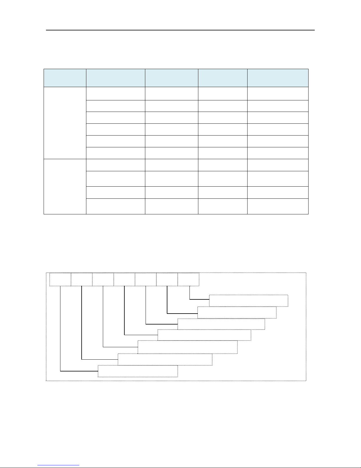
3). External Appearance
LSBLG255/MZ~ LSBLG860/MZ
LSBLG970/MZ~ LSBLG1490/MZ
Page 9
DX type water-cooled screw chiller (PCB Control) MCAC-CTSM-2014-03
8
2. Features
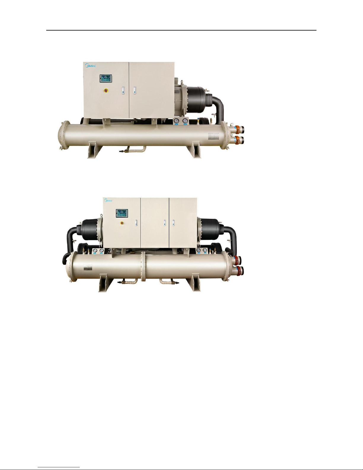
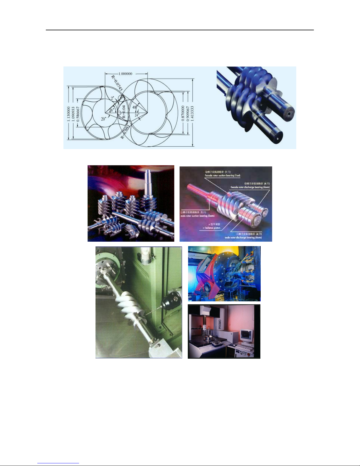
Leading technology of twin screw compressor
Midea screw chiller is equipped with the 3rd generation industrial
compressor that has the latest advanced 5-6 asymmetry dentiform
semi-hermetic screw rotors.
The rotors are processed by high-precision CNC and each part is
well-proportioned and none-gap matched, which minimizes the friction
resistance and clearance lost and also guarantees quiet running and
good duration.
High efficiency, energy saving
Extremely high full load and partial load energy efficiency.
New twin-rotor screw compressor equipped with a high-efficiency motor and a variable capacity
valve that can adjust the capacity of 25%, 50%, 75% and 100% in 4 stages (Stepless control as an
option) and permits exact matching of the cooling capacity to the actual load.
A decrease in chiller energy costs, particularly at the part-load conditions at which the chiller
operates most of the time.
Outstanding reliability
Full factory testing of the unit with water hookup helps provides a trouble-free start-up.
Extensive quality control checks during testing means that each equipment protection and operating
control is properly adjusted and operates correctly before it leaves the factory.
Transport simulation test in the laboratory on a vibrating table.
Factory-installed options minimize field expenses and startup labor.
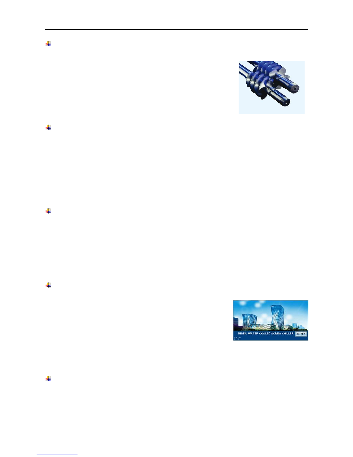
Intelligent control, easy operation
Microprocessor control as standard on all the units. A display
illustrates the machine’s operation status and programmable
parameters (set point) e.g. water temperature and refrigeration
pressure and temperature, allowing the operator to determine the
unit status and also allow changes to various set points. The control
system adopts PCB with predictive logic to select the most energy efficient combination of
compressors.
Easy and fast installation
The unit has passed full factory test before being delivered to ensure the reliable working on the
site. The unit can be placed in service only after being connected with power and water supply
during field installation.
Page 10
MCAC-CTSM-2014-03 DX type water-cooled screw chiller (PCB Control)
9
The installation and adjustment are simple .Standard flange connection and wire mesh to the
electrical panel. Refrigerant and lubrication oil are provided to the unit in the factory. Only piping
connection and power supply connection are required on the site.
Wide application range
Water cooled screw chiller are widely applied in school, hospital, shopping mall, office as well as the
factory and manufacturing processing area.
Page 11

DX type water-cooled screw chiller (PCB Control) MCAC-CTSM-2014-03
10
3. Specifications
Single head
LSBLGXXX/MZ
255
320
400
485
630
860
Cooling capacity
kW
253
318
400
485
628
859
Power input
kW
53.6
67
85
100
125
173
EER
kW/kW
4.73
4.75
4.71
4.85
5.02
4.97
Semi-hermetic screw compressor
Circuit A
Quantity 1 1 1 1 1 1
Circuit B
Quantity
--
--
--
--
--
--
Capacity Control
%
25%,50%,75%,100% four steps control
(25%,50%-100% Stepless as Option)
Oil recharge
Type
HBR-B01
Circuit A
L
14
14
15
18
23
28
Circuit B
L
--
--
--
--
--
--
Refrigerant
Type
R22
Circuit A
kg
35
40
60
80
110
160
Circuit B
kg
--
--
--
--
--
--
Control Type
TXV
TXV
TXV
TXV
TXV
EXV
Evaporator
Type
Shell-tube Direct Expansion Evaporator
Water content
L
100
150
80
120
340
290
Water flow
m³/h
43.5
54.7
68.8
83.4
108
147.7
Pressure drop
kPa
41
36
73
54
65
65
Connection Type
Victaulic coupling
Max. pressure
MPa 1 1 1 1 1 1
Water inlet/outlet pipe dia.
mm
80
80
100
125
125
150
Condenser
Type
Tube-and shell condenser
Water content
L
150
150
130
160
320
260
Water flow
m³/h
54.4
68.4
86
104.3
135
184.7
Pressure drop
kPa
36
41
22
49
81
41
Max. pressure
MPa 1 1 1 1 1 1
Water inlet/outlet pipe dia.
mm
80
80
100
125
125
150
Unit length
mm
2800
2800
2860
3200
3430
3430
Unit width
mm
1165
1165
1285
1300
1480
1610
Unit height
mm
1350
1350
1420
1450
1600
1730
Shipping weight
kg
1540
1870
2250
2610
2975
3780
Running weight
kg
1840
2070
2550
2910
3375
4180
Safety protection device
The following safety devices are equipped as standard.
High pressure (pressure switch);Low pressure (pressure sensor)
Compressor thermal protection
High discharge temperature on the compressor
Phase monitor; Low-pressure ratio; Low oil level protection
Interrupter protection ;Overload compressor protection
Over-voltage & low- voltage protection
Sensor malfunction protection
Contactor malfunction protection
Freeze protection
Note:
Nominal cooling capacities are based on the following conditions:
Chilled water inlet/outlet temp: 12℃/7℃; (53.6F/44.6F); Cooling water inlet/outlet temperature 30/35℃ (86F/96F).
The design fouling factor for both evaporator and condenser are 0.086 m2. ℃/kW, otherwise can be customized.
Page 12

MCAC-CTSM-2014-03 DX type water-cooled screw chiller (PCB Control)
11
Dual heads
LSBLGXXX/MZ
970
1060
1260
1490
Cooling capacity
kW
970
1057
1256
1487
Power input
kW
200
214
250
298
EER
kW/kW
4.85
4.94
5.02
4.99
Semi-hermetic screw compressor
Circuit A
Quantity 1 1 1 1
Circuit B
Quantity 1 1 1 1
Capacity Control
%
25%,50%,75%,100% four step control
(25%,50%-100% Stepless as Option)
Oil recharge
Type
HBR-B01
Circuit A L 18
18
23
23
Circuit B L 18
23
23
28
Refrigerant
Type
R22
Circuit A
kg
80
80
110
110
Circuit B
kg
80
90
110
130
Control Type
TXV
TXV
TXV
TXV+EXV
Evaporator
Type
Shell-tube Direct Expansion Evaporator
Water content
L
360
530
740
660
Water flow
m³/h
166.8
181.8
216
255.8
Pressure drop
kPa
83
85
87
76
Connection Type
Victaulic coupling
Max. pressure
MPa 1 1 1 1
Water inlet/outlet pipe dia.
mm
150
150
200
200
Condenser
Type
Tube-and shell condenser
Water content
L
360
320
460
430
Water flow
m³/h
208.6
227.3
270
319.7
Pressure drop
kPa
40
99
56
99
Max. pressure
MPa 1 1 1 1
Water inlet/outlet pipe dia.
mm
150
150
200
200
Unit length
mm
4100
4100
4450
4600
Unit width
mm
1630
1740
1780
1810
Unit height
mm
1680
1680
1730
1920
Shipping weight
kg
4630
4870
5840
6490
Running weight
kg
5080
5320
6340
7090
Safety protection device
The following safety devices are equipped as standard.
High pressure (pressure switch)
Low pressure (pressure sensor)
Compressor thermal protection
High discharge temperature on the compressor
Phase monitor; Low-pressure ratio; Low oil level protection
Interrupter protection; Overload compressor protection
Over-voltage & low- voltage protection
Sensor malfunction protection
Contactor malfunction protection
Freeze protection
Note:
Nominal cooling capacities are based on the following conditions:
Chilled water inlet/outlet temp: 12℃/7℃; (53.6F/44.6F); Cooling water inlet/outlet temperature 30/35℃ (86F/96F).
The design fouling factor for both evaporator and condenser are 0.086 m2. ℃/kW, otherwise can be customized.
Page 13
DX type water-cooled screw chiller (PCB Control) MCAC-CTSM-2014-03
12
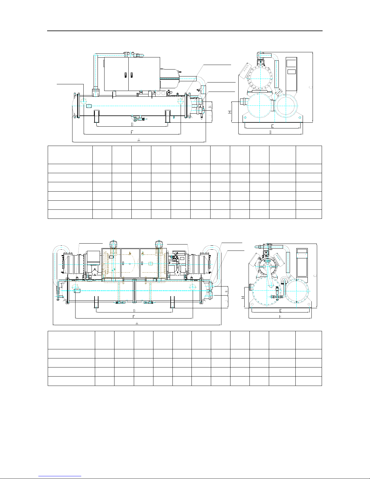
4.Outline Dimension
Single head
Chilled Water Inlet
Chilled Water Outlet
Cooling Water Outlet
Cooling Water Inlet
Model
A B C D E F H J K
Cooling
Water
In/outlet
Chilled
Water
In/outlet
LSBLG255/MZ
2800
1165
1350
1600
880
1780
280
210
140
DN80
DN80
LSBLG320/MZ
2800
1165
1350
1600
880
1760
280
210
140
DN80
DN80
LSBLG400/MZ
2860
1285
1420
1600
1000
1780
328
246
160
DN100
DN100
LSBLG485/MZ
3200
1300
1450
1600
1000
1660
330
230
200
DN125
DN125
LSBLG630/MZ
3430
1480
1600
1800
1220
2150
360
260
200
DN125
DN125
LSBLG860/MZ
3430
1610
1730
1800
1360
2120
400
300
200
DN150
DN150
Dual heads
Chilled Water Outlet
Chilled Water Inlet
Cooling Water Outlet
Cooling Water
Inlet
Model
A B C D E F H J K
Cooling
Water
In/outlet
Chilled
Water
In/outlet
LSBLG970/MZ
4100
1630
1680
1800
1440
2120
415
290
200
DN150
DN150
LSBLG1060/MZ
4100
1740
1680
1800
1440
2680
415
290
200
DN150
DN150
LSBLG1260/MZ
4450
1780
1730
2000
1540
3080
415
285
260
DN200
DN200
LSBLG1490/MZ
4600
1810
1920
2000
1640
3080
650
340
260
DN200
DN200
NOTE: Drawings are not contractually binding. Before designing an installation, consult the certified dimensional drawings
supplied with the unit or available on request.
For the positioning of the fixing points, weight distribution and center of gravity coordinates please refer to the dimensional
drawings.
Page 14
MCAC-CTSM-2014-03 DX type water-cooled screw chiller (PCB Control)
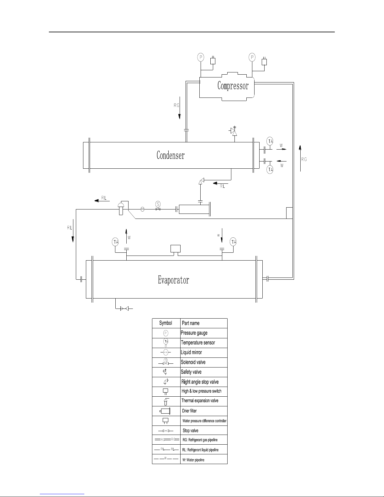
13
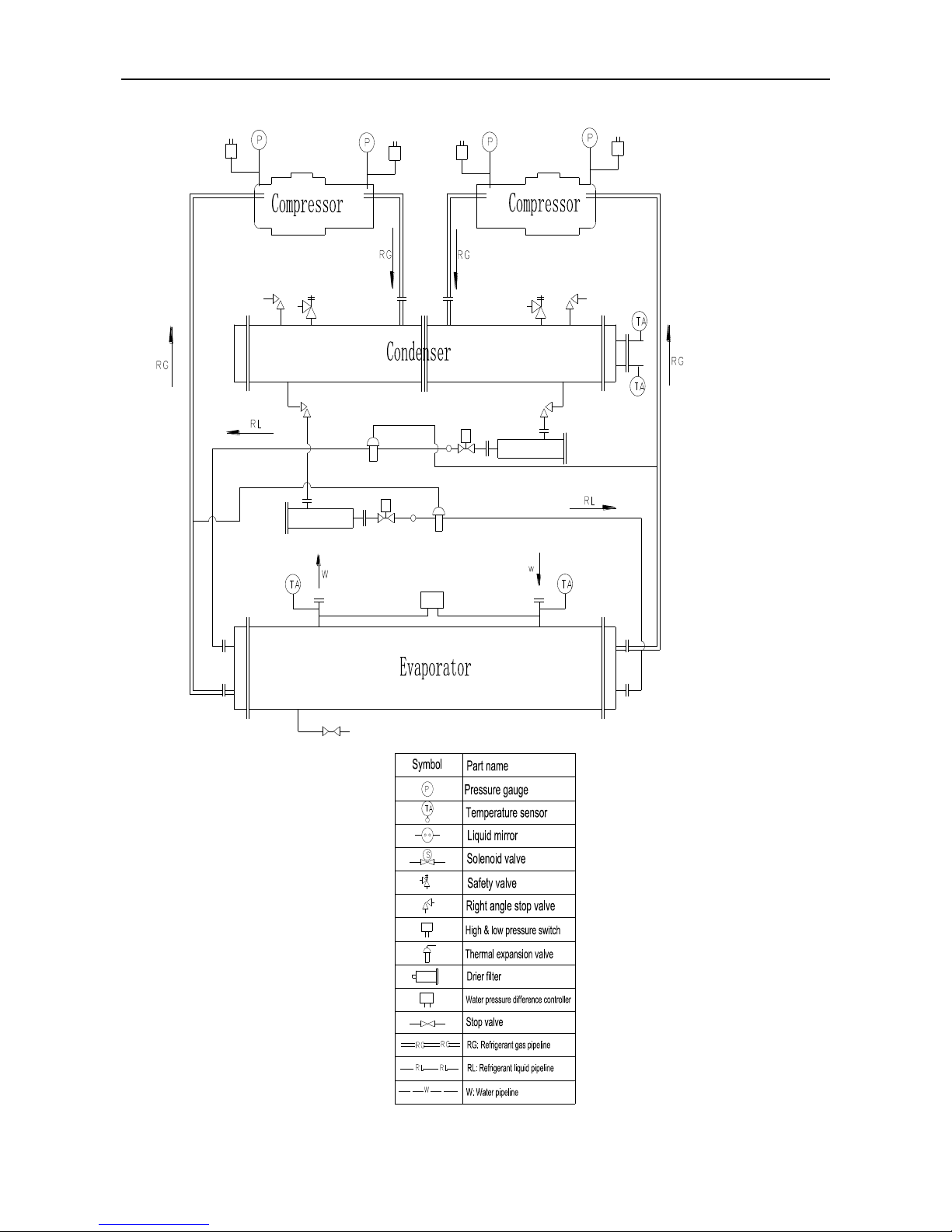
5.Refrigeration system
For single head unit (LSBLG255~630/MZ)
Page 15
DX type water-cooled screw chiller (PCB Control) MCAC-CTSM-2014-03
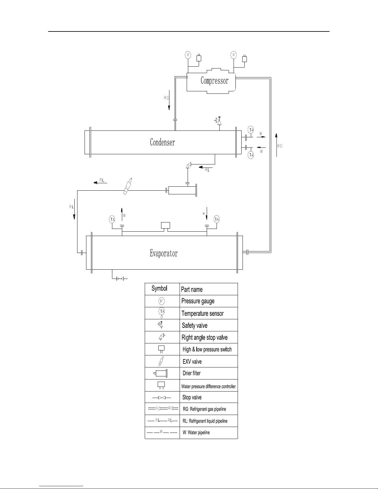
14
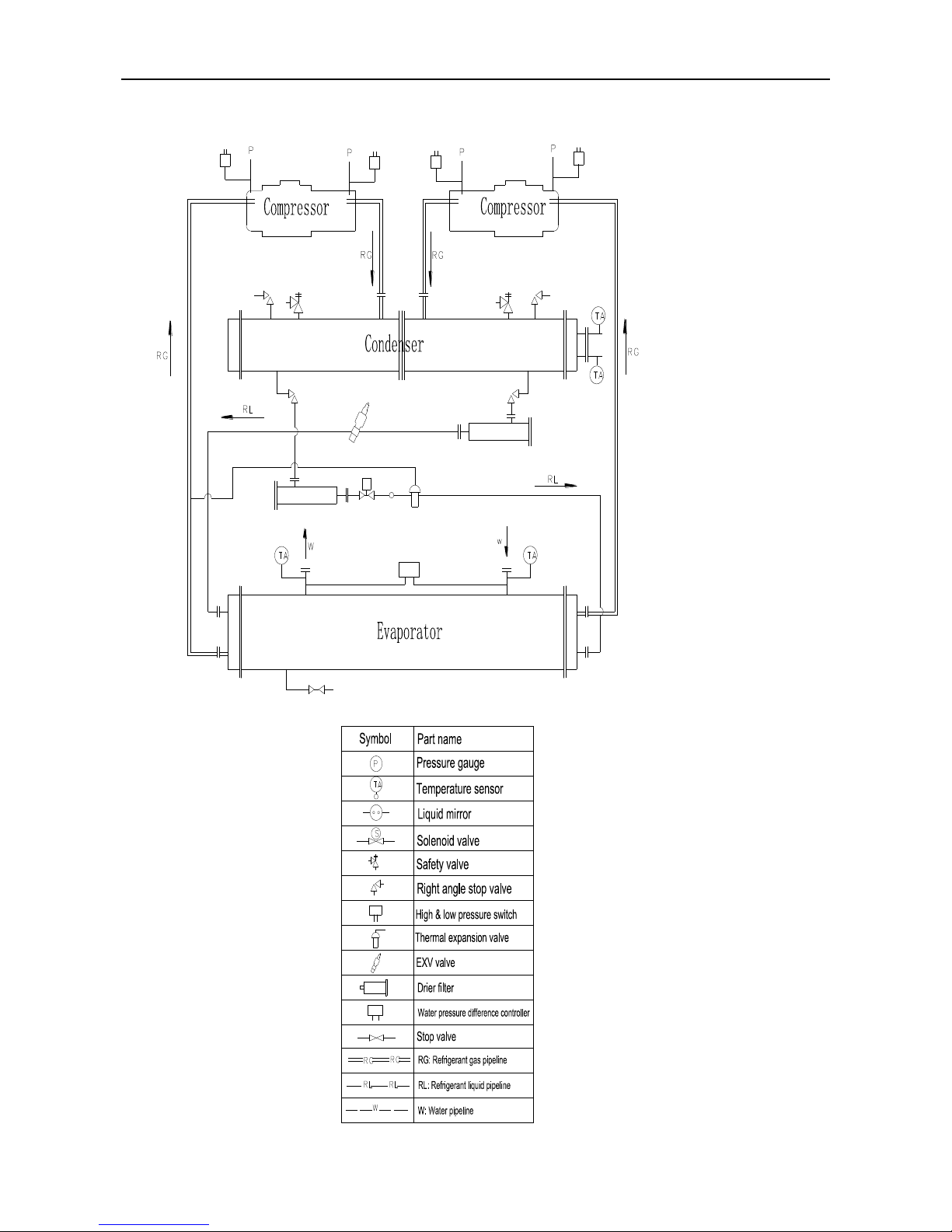
For single head unit (LSBLG860/MZ)
Page 16
MCAC-CTSM-2014-03 DX type water-cooled screw chiller (PCB Control)
15
For dual heads unit (LSBLG970~1260/MZ)
Page 17
DX type water-cooled screw chiller (PCB Control) MCAC-CTSM-2014-03
16
For dual heads unit (LSBLG1490/MZ)
Page 18
MCAC-CTSM-2014-03 DX type water-cooled screw chiller (PCB Control)
17
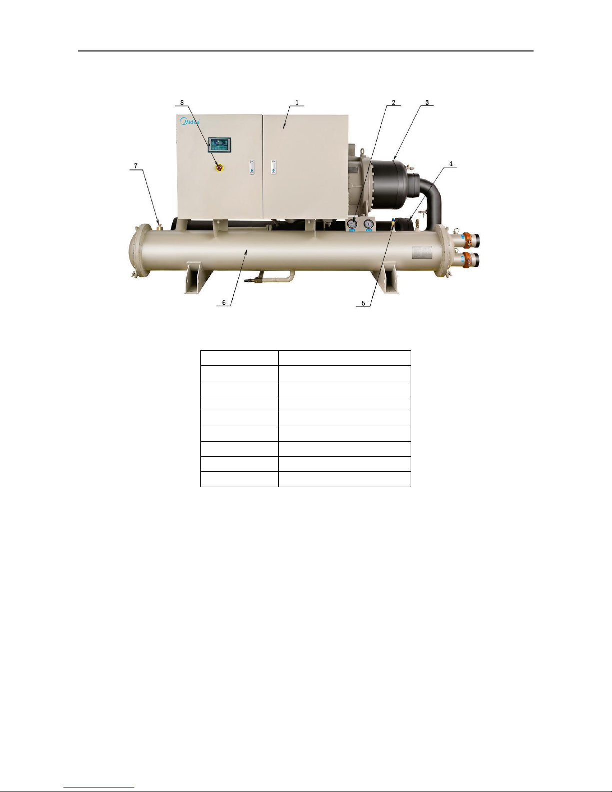
6. Major System Components
Major components of the unit
(1)Single compressor parataxis type unit
No.
Name
1
Controller
2
Pressure Gauge
3
Compressor
4
Evaporator
5
Safety Valve
6
Condenser
7
Expansion Valve
8
Emergency Stop
Page 19
DX type water-cooled screw chiller (PCB Control) MCAC-CTSM-2014-03
18
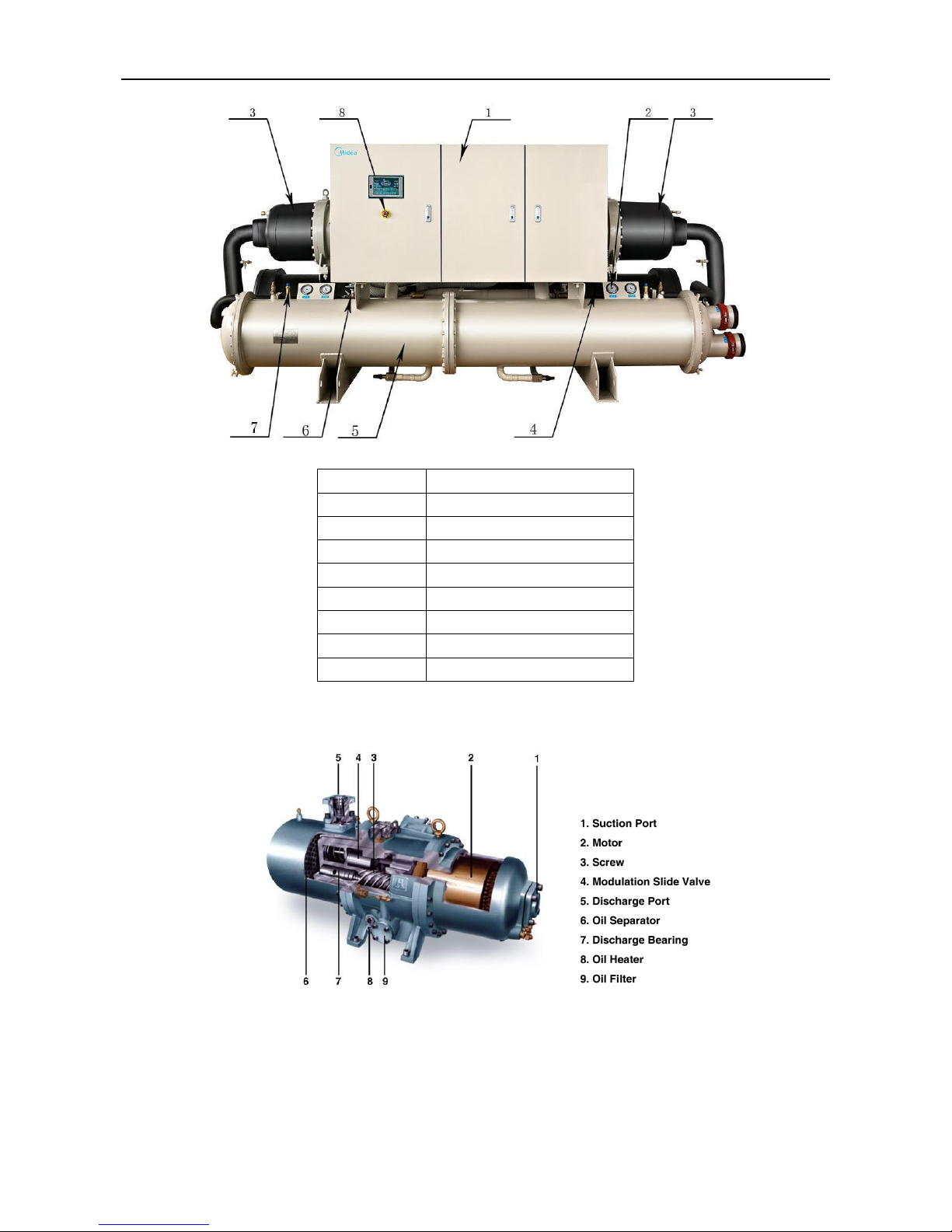
(2) Dual compressors parataxis type unit
No.
Name
1
Controller
2
Pressure Gauge
3
Compressor
4
Evaporator
5
Condenser
6
Expansion Valve
7
Safety Valve
8
Emergency Stop
6.1 Compressor
Advanced twin screw compressor
Midea screw chiller equipped with the 3rd generation industrial compressor that has the latest
advanced 5-6 asymmetry dentiform semi-hermetic screw rotors. The rotors are processed by
high-precision CNC and each part is well-proportioned and none-gap matching, which minimizes the
friction resistance and clearance lost, guarantees quiet running and good duration.
Compressors have a infinitely variable control down to 25% of its total capacity. This control is made
by means of capacity slides controlled by microprocessors.
Standard starter is star-delta type. Infinitely capacity control type is available (as option).
Page 20
MCAC-CTSM-2014-03 DX type water-cooled screw chiller (PCB Control)
19
With 5-6 asymmetry dentiform, the screw rotor gained patent by improving the shape of German
rotor GHH, proved having good balance, small vibration, and low noise due to balance testing by special
machine. Comparing with normal screw rotor with 4-6 dentiform, heat efficiency of the rotor with male
and female rotor adopting 5-6 dentiform increase by 10-12% and energy saves by 25%, the rotor also
gained British and American patent.
The bearing of compressor is from SKF, Sweden, the long lifespan of which ensures screw-type
main unit to run continuously more than 50,000 hours.
Page 21
DX type water-cooled screw chiller (PCB Control) MCAC-CTSM-2014-03
20
Lubricant:
The lubricant is supplied automatically by pressure difference inside the compressor. It is unnecessary to
add an extra lubricant pump.
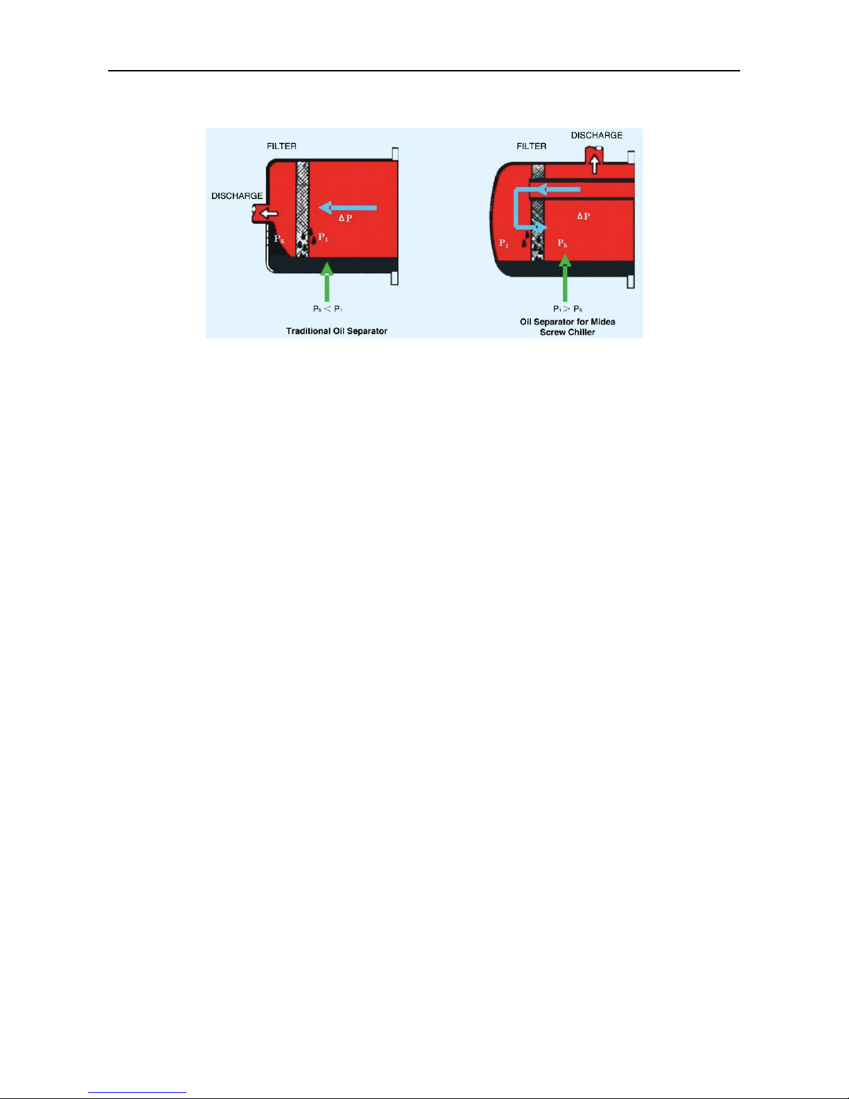
The Oil Separator comes from MANN of Germany and has reliable qualification. The oil content can
be controlled below 3ppm (the oil content treated by oil-gas separator of common like screw-type air
compressor is no less than 8-10ppm). The oil-gas separator amount is double of same kind of other
products. The large oil filtering area reduces refrigerant flux speed, and has better separating affect and
long lifespan by the secondary reflux technology adopted.
6.2 Pressure vessels
6.2.1 General
Monitoring during operation, re-qualification, re-testing and re-testing dispensation:
Follow the regulations on monitoring pressurized equipment.
It is normally required that the user or operator sets up and maintains a monitoring and maintenance
file.
Follow the control programs.
If they exist follow local professional recommendations.
Regularly inspect the condition of the coating (paint) to detect blistering resulting from corrosion. To
do this, check a non-insulated section of the container or the rust formation at the insulation joints.
Regularly check for possible presence of impurities (e.g. silicon grains) in the heat exchange fluids.
These impurities maybe the cause of the wear or corrosion by puncture
Filter the heat exchange fluid check and carry out internal inspections as described in EN 378-2.
In case of re-testing please refer to the maximum operating pressure given on the unit nameplate.
The reports of periodical checks by the user or operator must be included in the supervision and
maintenance file.
6.2.2 Repair
Any repair or modification, including the replacement of moving parts:
Must follow local regulations and be made by qualified operators and in accordance with qualified
procedures, including changing the heat exchanger tubes.
Must be made in accordance with the instructions of the original manufacturer. Repair and
modification that necessitate permanent assembly (soldering, welding, expanding etc.) must be made
using the correct procedures and by qualified operators.
An indication of any modification or repair must be shown in the monitoring and maintenance file.
6.2.3 Corrosion allowances:
Gas side: 0 mm
Heat exchange fluid side: 1 mm for tubular plates in lightly alloyed steels, 0 mm for stainless steel plates
or plates with copper-nickel or stainless steel protection.
6.2.4 Operating life
The evaporator and condenser are designed for: prolonged usage of 20 years for high-quality materials.
6.2.5 Security
Page 22
MCAC-CTSM-2014-03 DX type water-cooled screw chiller (PCB Control)
21
The condenser is equipped with safety valves. And ball valve is connecting safety valve to condenser.
The ball valve maintain full-state, it is closed only when safety valve is opening or replaced.
Ball valve can protect life and property because it can prevent refrigerant from flowing into the air when
safety valve is opening or replaced.
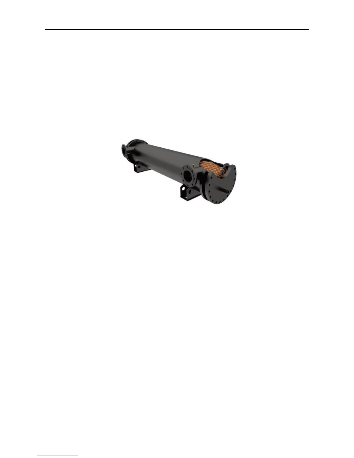
6.2.6 Evaporator
Midea Screw Chiller is equipped with high efficiency shell and tube evaporator that are constructed by
seamless steel tube with anti-corrosive treatment. The evaporator is a direct expansion type with
refrigerant inside the copper tubes and water on the outside. The copper tubes are roll expanded into
carbon steel tube plates.
Constructed with seamless integrally finned copper, the water pipe system makes the evaporator attain
optimal heat exchange efficient. Also they are removable, which makes it available for efficient. Also they
are removable, which makes it available for altering water piping arrangement.
The design working pressure for both evaporator and condenser are 1.0MPa, higher pressure demand
can be customized.
6.2.7 Condenser
Shell and tube operates with refrigerant in shell and water in tubes. Replaceable water tubes are
fabricated from integral finned cooper and mechanically bonded to steel tube sheets. The condenser is
GB151-1999 (Chinese standard) designed, constructed, inspected and stamped. Water side working
pressure is designed for 1.0MPa.
The condenser is used high-efficient tubes to enhance its transfer performance. Meanwhile, the system's
COP can be increased largely by adding the subcooler.
6.2.8 Throttle valve
The chiller is equipped with expansion valve to decompress and expanse refrigerant.
7.Water Flow
Balance the chilled water flow through the evaporator and the condenser water flow through the
condenser. The flow rates must fall between the minimum and maximum values shown in the below
table. Flow rates below the minimum values shown will result in laminar flow which will reduce efficiency,
cause erratic operation of the electronic expansion valve and could cause low temperature cutouts. On
the other hand, flow rates exceeding the maximum values shown can cause erosion on the heat
exchanges water connections and tubes, even piping breaking.
Variable chilled water flow through the heat exchanges while the compressor(s) are operating is not
recommended. The chiller control set points are based upon a constant flow and variable temperature.
Page 23
DX type water-cooled screw chiller (PCB Control) MCAC-CTSM-2014-03
22
Model
Evaporator water flow rate m3/h
Condenser water flow rate m3/h
Chilled water
minimum
Chilled water
rated
Chilled water
maximum
Cooling water
minimum
Cooling water
rated
Cooling water
maximum
LSBLG255/MZ
31
44
57
38
54
70
LSBLG320/MZ
38
55
71
48
68
88
LSBLG400/MZ
48
69
90
60
86
111
LSBLG485/MZ
58
83
108
74
104
134
LSBLG630/MZ
76
108
140
95
135
176
LSBLG860/MZ
104
148
192
129
184
239
LSBLG970/MZ
117
167
217
146
209
271
LSBLG1060/MZ
127
182
237
159
227
295
LSBLG1260/MZ
151
216
281
189
270
351
LSBLG1490/MZ
179
256
333
224
320
416
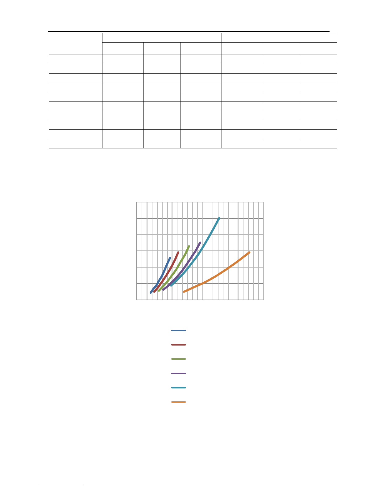
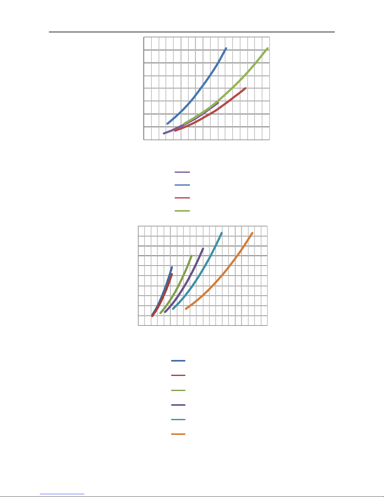
Pressure drop
DX type (Evaporator)
Press ure drop (kPa)
Water flow (m3/h)
0
20
40
60
80
100
120
0 50 100 150 200 250
LSBLG255/MZ
LSBLG320/MZ
LSBLG400/MZ
LSBLG485/MZ
LSBLG630/MZ
LSBLG860/MZ
Page 24
MCAC-CTSM-2014-03 DX type water-cooled screw chiller (PCB Control)
23
Press ure drop (kPa)
Water flow (m3/h)
0
20
40
60
80
100
120
140
160
50 150 250 350
LSBLG970/MZ
LSBLG1060/MZ
LSBLG1260/MZ
LSBLG1490/MZ
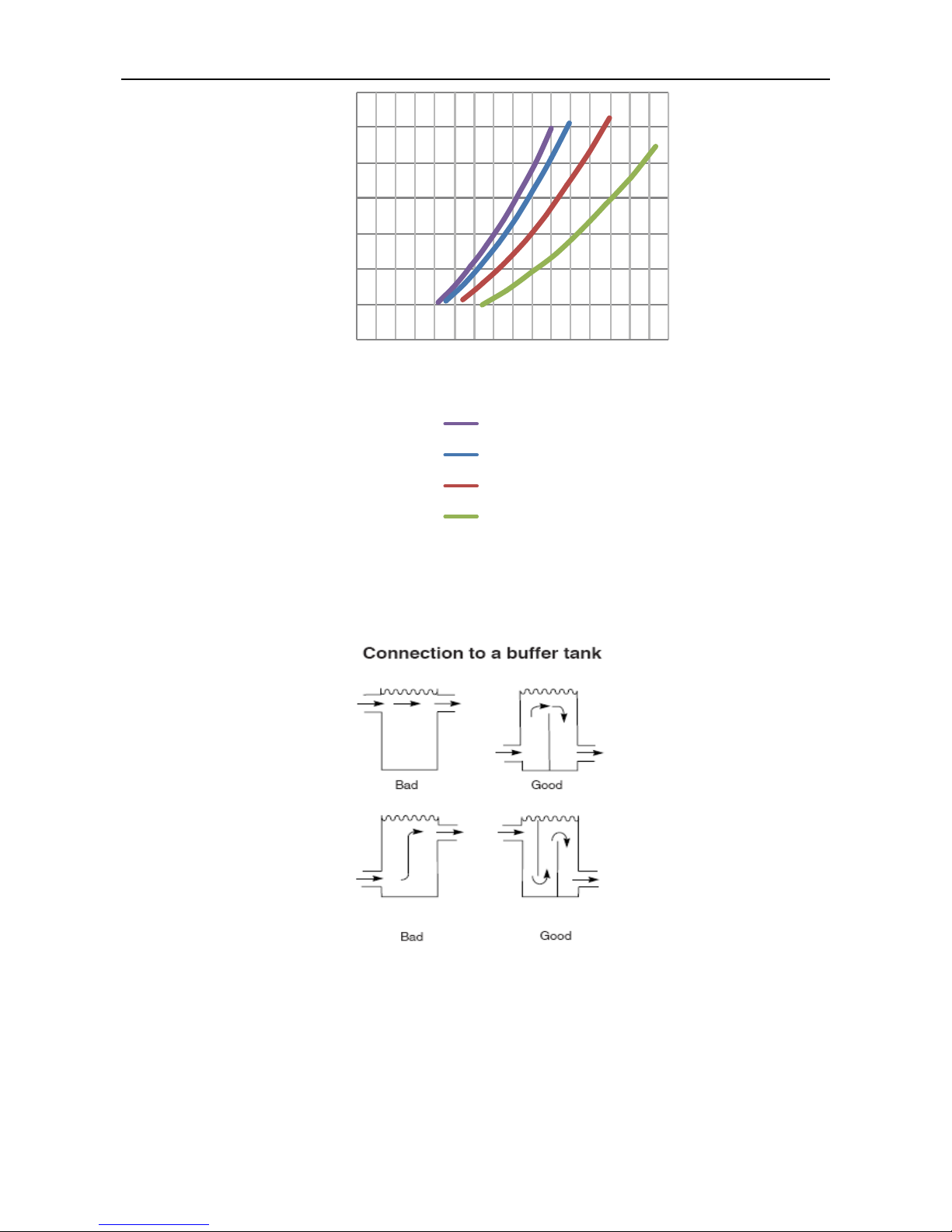
DX type (Condenser)
0
10
20
30
40
50
60
70
80
90
100
0 50 100 150 200
LSBLG255/MZ
LSBLG320/MZ
LSBLG400/MZ
LSBLG485/MZ
LSBLG630/MZ
LSBLG860/MZ
Pressure drop (kPa)
Water flow (m3/h)
Page 25
DX type water-cooled screw chiller (PCB Control) MCAC-CTSM-2014-03
24
Press ure drop (kPa)
Water flow (m3/h)
0
20
40
60
80
100
120
140
0 100 200 300
LSBLG970/MZ
LSBLG1060/MZ
LSBLG1260/MZ
LSBLG1490/MZ
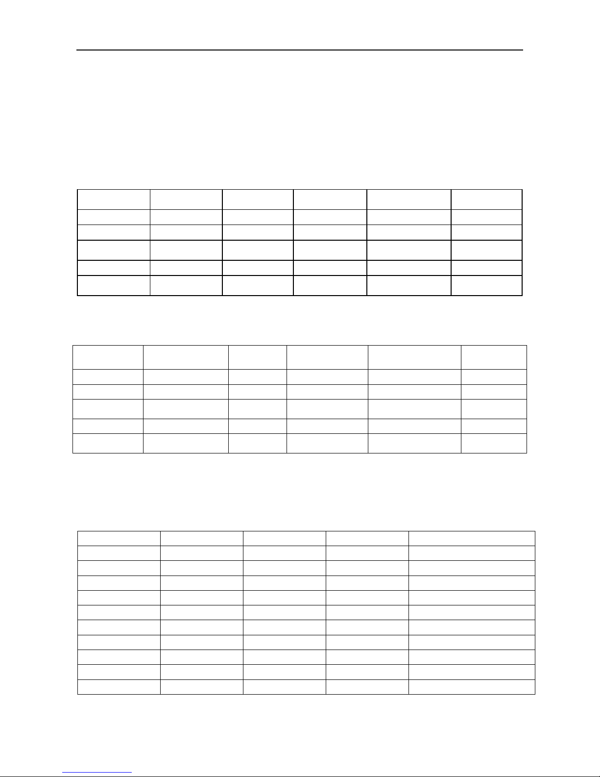
System minimum water volume:
It is often necessary to add a buffer water tank to the circuit in order to achieve the required water
volume. The tank itself must be internally baffled in order to ensure proper mixing of the liquid (water or
brine). Water tank volume is large than 1 / 10 whole system water volume at least.
Refer to the examples below.
How to calculate minimum volume in pipeline system:
W=QgT/CP▽t
W — Minimum water volume(kg);
Qg — Total cooling/heating capacity of the terminal(kW);
T — Thermal stability time requirement,Take(8~10)×60s;
CP — Water specific heat at constant pressure,4.187kj/(kg·℃);
▽t — Water temperature fluctuation required value,take 5℃。
Page 26
MCAC-CTSM-2014-03 DX type water-cooled screw chiller (PCB Control)
25
For system, Qg is calculated according to the lowest load so that it operates steadily.
It can also calculated according to 0.5Q(50%). T takes 8 minutes, the shortest time that the unit
running. That is 480s. Cp=4.18kj/kg, ▽t =5℃
According to the above formula, the result is as following:
W=0.5Q*480/(4.18*5)=11.48Q kg
Note:
The above formula is only for reference, different factor should be adopted to suit for different condition.
8. Unit sound levels
Unit Model
Compressor
Model
Sound pressure
level(dB)
Unit Model
Compressor Model
Sound pressure
level(dB)
LSBLG255/MZ
RC-2-M255B
80.7
LSBLG860/MZ
RC-2-M860B
83
LSBLG320/MZ
RC-2-M320B
81
LSBLG970/MZ
2×RC-2-M485B
83.3
LSBLG400/MZ
RC-2-M400B
81.4
LSBLG1060/MZ
RC-2-M485B +
RC-2-M570B
83.5
LSBLG485/MZ
RC-2-M485B
81.7
LSBLG1260/MZ
2×RC-2-M630B
84
LSBLG630/MZ
RC-2-M630B
82.5
LSBLG1490/MZ
RC-2-M630B +
RC-2-M860B
84.6
9. Compressor oil
Refrigeration oil type is subject to the compressor nameplate. The compressor recommended oil level
are as follow:
Unit Model
Compressor Model
Oil level(L)
Unit Model
Compressor Model
Oil level(L)
LSBLG255/MZ
RC-2-M255B
14
LSBLG860/MZ
RC-2-M860B
28
LSBLG320/MZ
RC-2-M320B
14
LSBLG970/MZ
2×RC-2-M485B
2×18
LSBLG400/MZ
RC-2-M400B
15
LSBLG1060/MZ
RC-2-M485B +
RC-2-M570B
18+23
LSBLG485/MZ
RC-2-M485B
18
LSBLG1260/MZ
2×RC-2-M630B
2×23
LSBLG630/MZ
RC-2-M630B
23
LSBLG1490/MZ
RC-2-M630B +
RC-2-M860B
23+28
10. Recommend breaker current
All units has equipped with breaker with user. All refrigerant circuit repairs must be carried out by a
trained, qualified and skilled technician and following local regulations
Midea recommended breaker current for units as follow:
Model
Rated current (A)
Maximal current (A)
Start current (A)
Recommend breaker current
LSBLG255/MZ
92
120
230
171
LSBLG320/MZ
119
148
260
203
LSBLG400/MZ
146
189
292
268
LSBLG485/MZ
171
205
407
310
LSBLG630/MZ
213
277
503
393
LSBLG860/MZ
295
383
785
534
LSBLG970/MZ
341
445
407
620
LSBLG1060/MZ
365
458
443
665
LSBLG1260/MZ
427
554
503
786
LSBLG1490/MZ
509
662
785
927
Note: 970-1490 models are the dual compressor units, because two compressors do not start at the
Page 27
DX type water-cooled screw chiller (PCB Control) MCAC-CTSM-2014-03
26
same time, so the starting current of 970-1490 models are the single compressor start-up current value.
Note:
(1) Values obtained at standard unit operating conditions: evaporator entering/leaving water
temperature = 12°C/7°C. Condenser entering/leaving water temperature = 30°C/35°C.
(2) For the dual compressor unit, we suggest equipped with breaker for each circuit.
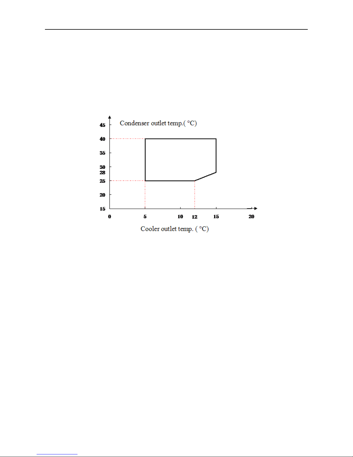
11.Operating Range
Content
Running range
Chilled Leaving Water Temperature
5℃~15℃
Cooling Entering water Temperature
20℃~35℃
Water flow volume
Rating flow volume ±20%
Inlet/outlet water Temp. difference
3.8℃~ 7.1℃
Fouling factor (m2.℃/kW)
0.086
Voltage tolerance
Rating Voltage±10%
Phase tolerance
±2%
Power supply frequency
Rating frequency±2%
Evaporator max working pressure on water side
1.0MPa
Compressor max. start count
4 times/h
Environment quality
High corrosive environment and high
humidity should be avoided.
Drainage system
The height of water drainage should not be
higher than the base of the unit on the spot
Normal operation ambient temperature
-10℃~45℃
Storage and transport temperature
-15℃~50℃
Applicable altitude range:
No more than 1000m
Operating limits and changes water temperature curve
LSBLG***/MZ evaporator
Minimum
Maximum
Entering temperature at start-up
12°C
35°C
Leaving temperature during operation
5°C
15°C
Entering/leaving temperature difference at full load
3.8°C
7.1°C
LSBLG***/MZ condenser
Minimum
Maximum
Entering temperature at start-up
19°C
35°C
Leaving temperature during operation
25°C
40°C
Entering/leaving temperature difference at full load
3.8°C
7.1°C
Note:
Page 28
MCAC-CTSM-2014-03 DX type water-cooled screw chiller (PCB Control)
27
(1) For low-temperature applications, where the leaving water temperature is below 5°C, freeze protection switch will
work unit stop.
(2) If the temperature leaving the condenser is below 19°C,the unit will stop and warning.
(3) Ambient temperatures: During storage and transport of the LSBLG***/M units. Including by container the minimum
and maximum permissible temperatures is -20°C ~50°C.
Changes water temperature curve in the operation
Page 29
DX type water-cooled screw chiller (PCB Control) MCAC-CTSM-2014-03
28
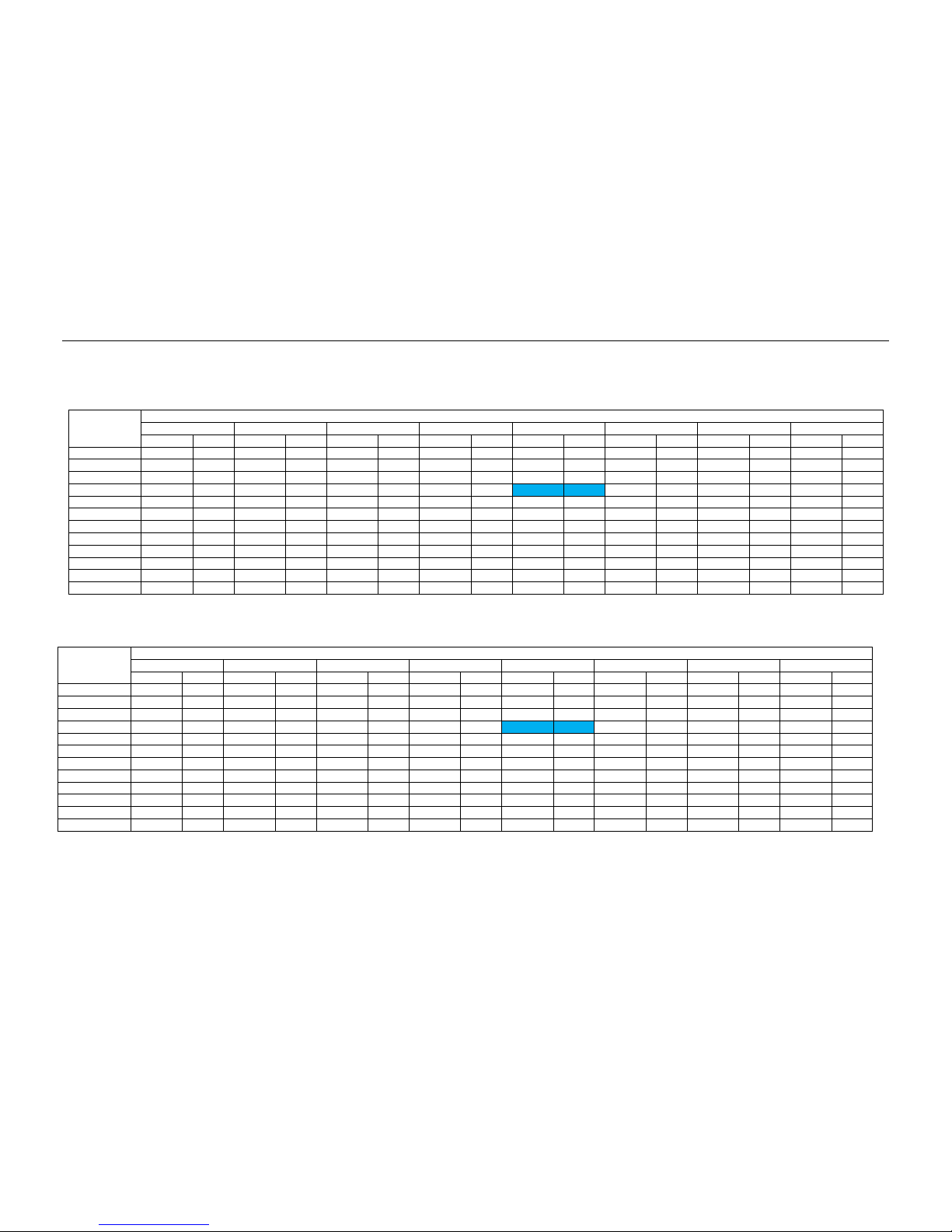
12.Capacity table
LSBLG255/MZ
LSBLG320/MZ
Chilled Water
Outlet Temp.
Cooling Water Inlet Temp.(°C)
25.00
26.00
27.00
29.00
30.00
32.00
33.00
35.00
Capacity
Power
Capacity
Power
Capacity
Power
Capacity
Power
Capacity
Power
Capacity
Power
Capacity
Power
Capacity
Power
(°C)
kW
kW
kW
kW
kW
kW
kW
kW
kW
kW
kW
kW
kW
kW
kW
kW
5.00
292.48
58.91
289.33
59.90
286.18
60.95
279.58
63.06
276.13
64.11
269.22
66.48
265.76
67.61
258.83
70.04
6.00
313.85
60.19
310.23
61.19
306.92
62.25
299.85
64.45
296.32
65.52
288.94
67.86
285.39
69.07
277.99
71.54
7.00
336.55
61.47
333.16
62.55
329.45
63.63
321.72
65.85
318.00
67.00
310.31
69.37
306.31
70.59
298.30
73.09
8.00
361.30
62.94
357.47
64.03
353.64
65.06
345.64
67.31
341.47
68.54
333.14
70.94
328.97
72.17
320.39
74.72
9.00 / /
383.14
65.38
378.84
66.56
370.26
68.85
365.97
70.10
357.39
72.53
352.76
73.78
343.83
76.42
10.00
/ / 409.86
66.89
405.45
68.02
396.61
70.41
392.19
71.61
382.53
74.07
377.62
74.69
367.81
78.11
11.00
/ / 437.53
68.29
432.95
69.43
423.46
71.92
418.53
73.14
408.67
75.70
403.73
76.99
393.25
79.71
12.00
/ / 468.23
69.93
463.49
71.08
453.29
73.54
447.82
74.84
437.25
77.44
432.15
78.74
421.19
81.56
13.00
/ / / / 494.29
72.61
483.75
75.17
478.10
76.49
466.79
79.12
461.14
80.51
449.89
83.37
14.00
/ / / / 526.91
74.23
515.69
76.82
509.89
78.09
497.90
80.83
492.08
82.32
479.67
85.22
15.00
/ / / / 561.75
75.93
549.81
78.56
543.83
79.84
531.47
82.62
525.10
84.06
511.96
87.07
Note: The inlet/outlet water temperature difference is 5 ℃.
Chilled Water
Outlet Temp.
Cooling Water Inlet Temp.(°C)
25.00
26.00
27.00
29.00
30.00
32.00
33.00
35.00
Capacity
Power
Capacity
Power
Capacity
Power
Capacity
Power
Capacity
Power
Capacity
Power
Capacity
Power
Capacity
Power
(°C)
kW
kW
kW
kW
kW
kW
kW
kW
kW
kW
kW
kW
kW
kW
kW
kW
5.00
232.70
47.13
230.19
47.92
227.68
48.76
222.43
50.45
219.69
51.29
214.19
53.19
211.44
54.08
205.93
56.04
6.00
249.70
48.15
246.82
48.95
244.18
49.80
238.56
51.56
235.75
52.42
229.88
54.29
227.06
55.25
221.17
57.23
7.00
267.76
49.18
265.06
50.04
262.11
50.90
255.96
52.68
253.00
53.60
246.88
55.49
243.70
56.47
237.32
58.47
8.00
287.45
50.35
284.40
51.22
281.35
52.04
274.99
53.85
271.67
54.84
265.04
56.75
261.73
57.74
254.90
59.77
9.00 / /
304.82
52.30
301.40
53.25
294.58
55.08
291.17
56.08
284.34
58.02
280.66
59.02
273.55
61.14
10.00
/ / 326.08
53.51
322.57
54.42
315.54
56.33
312.02
57.29
304.34
59.25
300.44
59.76
292.63
62.49
11.00
/ / 348.10
54.64
344.46
55.55
336.90
57.54
332.98
58.51
325.14
60.56
321.21
61.59
312.87
63.77
12.00
/ / 372.52
55.94
368.75
56.87
360.64
58.83
356.28
59.87
347.88
61.95
343.81
62.99
335.10
65.25
13.00
/ / / / 393.25
58.09
384.87
60.14
380.37
61.19
371.38
63.30
366.88
64.41
357.93
66.70
14.00
/ / / / 419.21
59.38
410.28
61.46
405.67
62.47
396.12
64.67
391.50
65.85
381.63
68.17
15.00
/ / / / 446.92
60.74
437.43
62.85
432.67
63.87
422.84
66.10
417.77
67.24
407.31
69.66
Page 30
MCAC-CTSM-2014-03 DX type water-cooled screw chiller (PCB Control)
29
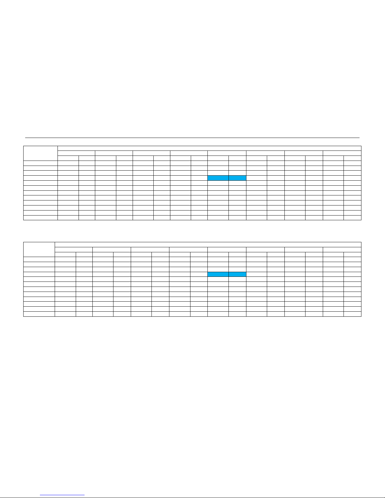
LSBLG400/MZ
Chilled Water
Outlet Temp.
Cooling Water Inlet Temp.(°C)
25.00
26.00
27.00
29.00
30.00
32.00
33.00
35.00
Capacity
Power
Capacity
Power
Capacity
Power
Capacity
Power
Capacity
Power
Capacity
Power
Capacity
Power
Capacity
Power
(°C)
kW
kW
kW
kW
kW
kW
kW
kW
kW
kW
kW
kW
kW
kW
kW
kW
5.00
367.90
74.74
363.94
75.99
359.97
77.32
351.67
80.00
347.33
81.34
338.64
84.35
334.29
85.77
325.58
88.86
6.00
394.78
76.36
390.22
77.63
386.06
78.97
377.17
81.77
372.73
83.13
363.45
86.10
358.98
87.62
349.67
90.76
7.00
423.34
77.98
419.07
79.35
414.40
80.72
404.67
83.55
400.00
85.00
390.33
88.00
385.30
89.55
375.22
92.73
8.00
454.47
79.84
449.65
81.23
444.82
82.53
434.76
85.40
429.53
86.96
419.04
90.00
413.80
91.56
403.00
94.79
9.00
/ / 481.93
82.95
476.53
84.44
465.73
87.35
460.34
88.93
449.55
92.02
443.73
93.60
432.49
96.95
10.00
/ / 515.55
84.86
509.99
86.29
498.88
89.33
493.32
90.85
481.17
93.96
475.00
94.76
462.65
99.10
11.00
/ / 550.35
86.64
544.60
88.09
532.66
91.25
526.46
92.79
514.05
96.04
507.84
97.67
494.65
101.12
12.00
/ / 588.97
88.71
583.01
90.18
570.18
93.29
563.29
94.94
550.00
98.25
543.58
99.90
529.80
103.47
13.00
/ / / / 621.75
92.12
608.49
95.36
601.38
97.03
587.16
100.38
580.05
102.14
565.89
105.77
14.00
/ / / / 662.78
94.17
648.67
97.46
641.38
99.06
626.28
102.55
618.97
104.43
603.36
108.11
15.00
/ / / / 706.60
96.33
691.58
99.67
684.06
101.29
668.52
104.82
660.51
106.64
643.97
110.47
LSBLG485/MZ
Chilled Water
Outlet Temp.
Cooling Water Inlet Temp.(°C)
25.00
26.00
27.00
29.00
30.00
32.00
33.00
35.00
Capacity
Power
Capacity
Power
Capacity
Power
Capacity
Power
Capacity
Power
Capacity
Power
Capacity
Power
Capacity
Power
(°C)
kW
kW
kW
kW
kW
kW
kW
kW
kW
kW
kW
kW
kW
kW
kW
kW
5.00
446.08
87.93
441.28
89.40
436.47
90.97
426.40
94.12
421.14
95.69
410.61
99.23
405.33
100.90
394.76
104.54
6.00
478.66
89.84
473.14
91.33
468.09
92.91
457.32
96.20
451.93
97.80
440.68
101.29
435.27
103.09
423.98
106.78
7.00
513.30
91.74
508.12
93.35
502.46
94.96
490.67
98.29
485.00
100.00
473.28
103.53
467.17
105.35
454.95
109.09
8.00
551.05
93.93
545.20
95.57
539.35
97.10
527.15
100.47
520.80
102.31
508.09
105.88
501.73
107.72
488.64
111.52
9.00
/ / 584.34
97.58
577.79
99.34
564.70
102.76
558.16
104.63
545.07
108.25
538.02
110.12
524.39
114.06
10.00
/ / 625.10
99.84
618.37
101.52
604.89
105.09
598.15
106.88
583.42
110.55
575.93
111.48
560.96
116.59
11.00
/ / 667.30
101.93
660.32
103.63
645.84
107.35
638.33
109.16
623.28
112.99
615.75
114.90
599.76
118.97
12.00
/ / 714.12
104.37
706.90
106.09
691.34
109.76
682.99
111.70
666.88
115.58
659.09
117.52
642.38
121.73
13.00
/ / / / 753.87
108.37
737.79
112.19
729.18
114.16
711.93
118.09
703.31
120.17
686.15
124.44
14.00
/ / / / 803.62
110.79
786.51
114.66
777.67
116.55
759.37
120.65
750.51
122.86
731.58
127.19
15.00
/ / / / 856.75
113.33
838.54
117.25
829.43
119.16
810.58
123.32
800.86
125.46
780.81
129.96
Note: The inlet/outlet water temperature difference is 5 ℃.
Page 31

DX type water-cooled screw chiller (PCB Control) MCAC-CTSM-2014-03
30
LSBLG630/MZ
Chilled Water
Outlet Temp.
Cooling Water Inlet Temp.(°C)
25.00
26.00
27.00
29.00
30.00
32.00
33.00
35.00
Capacity
Power
Capacity
Power
Capacity
Power
Capacity
Power
Capacity
Power
Capacity
Power
Capacity
Power
Capacity
Power
(°C)
kW
kW
kW
kW
kW
kW
kW
kW
kW
kW
kW
kW
kW
kW
kW
kW
5.00
577.61
109.91
571.38
111.75
565.16
113.71
552.12
117.65
545.31
119.61
531.67
124.04
524.84
126.13
511.15
130.68
6.00
619.80
112.30
612.65
114.16
606.11
116.14
592.16
120.25
585.18
122.25
570.61
126.61
563.60
128.86
548.98
133.47
7.00
664.64
114.68
657.93
116.69
650.61
118.71
635.34
122.86
628.00
125.00
612.82
129.42
604.92
131.69
589.09
136.36
8.00
713.52
117.42
705.95
119.46
698.37
121.37
682.58
125.58
674.36
127.88
657.89
132.35
649.67
134.65
632.72
139.40
9.00 / /
756.63
121.98
748.15
124.18
731.20
128.45
722.73
130.78
705.79
135.32
696.65
137.65
679.01
142.58
10.00
/ / 809.41
124.80
800.69
126.90
783.24
131.37
774.51
133.60
755.44
138.18
745.75
139.35
726.36
145.74
11.00
/ / 864.06
127.41
855.02
129.54
836.27
134.19
826.54
136.45
807.06
141.24
797.31
143.63
776.60
148.71
12.00
/ / 924.68
130.46
915.33
132.62
895.18
137.20
884.37
139.62
863.50
144.48
853.42
146.91
831.79
152.17
13.00
/ / / / 976.14
135.47
955.33
140.24
944.17
142.70
921.84
147.61
910.68
150.21
888.45
155.55
14.00
/ / / / 1040.56
138.48
1018.41
143.33
1006.96
145.68
983.26
150.81
971.79
153.58
947.28
158.99
15.00
/ / / / 1109.36
141.66
1085.78
146.57
1073.98
148.95
1049.57
154.15
1036.99
156.82
1011.03
162.45
LSBLG860/MZ
Chilled Water
Outlet Temp.
Cooling Water Inlet Temp.(°C)
25.00
26.00
27.00
29.00
30.00
32.00
33.00
35.00
Capacity
Power
Capacity
Power
Capacity
Power
Capacity
Power
Capacity
Power
Capacity
Power
Capacity
Power
Capacity
Power
(°C)
kW
kW
kW
kW
kW
kW
kW
kW
kW
kW
kW
kW
kW
kW
kW
kW
5.00
790.07
152.11
781.56
154.66
773.04
157.38
755.21
162.82
745.89
165.54
727.24
171.67
717.89
174.56
699.17
180.86
6.00
847.78
155.42
838.00
157.99
829.06
160.74
809.98
166.43
800.43
169.19
780.50
175.23
770.92
178.34
750.92
184.73
7.00
909.12
158.72
899.94
161.50
889.93
164.29
869.04
170.04
859.00
173.00
838.24
179.11
827.43
182.26
805.77
188.73
8.00
975.97
162.51
965.62
165.33
955.26
167.98
933.65
173.81
922.41
176.99
899.89
183.17
888.64
186.36
865.45
192.93
9.00 / /
1034.95
168.82
1023.34
171.86
1000.16
177.78
988.58
181.00
965.40
187.28
952.90
190.51
928.77
197.33
10.00
/ / 1107.13
172.72
1095.21
175.63
1071.34
181.81
1059.40
184.90
1033.31
191.24
1020.06
192.87
993.54
201.70
11.00
/ / 1181.89
176.34
1169.52
179.28
1143.88
185.72
1130.57
188.85
1103.92
195.47
1090.58
198.79
1062.26
205.82
12.00
/ / 1264.80
180.56
1252.02
183.54
1224.45
189.88
1209.67
193.24
1181.13
199.96
1167.33
203.32
1137.74
210.60
13.00
/ / / / 1335.20
187.49
1306.73
194.09
1291.47
197.49
1260.92
204.30
1245.65
207.89
1215.26
215.28
14.00
/ / / / 1423.32
191.66
1393.02
198.36
1377.35
201.62
1344.94
208.72
1329.25
212.55
1295.72
220.04
15.00
/ / / / 1517.42
196.06
1485.17
202.85
1469.03
206.15
1435.64
213.34
1418.44
217.04
1382.92
224.83
Note: The inlet/outlet water temperature difference is 5 ℃.
Page 32

MCAC-CTSM-2014-03 DX type water-cooled screw chiller (PCB Control)
31
LSBLG970/MZ
Chilled Water
Outlet Temp.
Cooling Water Inlet Temp.(°C)
25.00
26.00
27.00
29.00
30.00
32.00
33.00
35.00
Capacity
Power
Capacity
Power
Capacity
Power
Capacity
Power
Capacity
Power
Capacity
Power
Capacity
Power
Capacity
Power
(°C)
kW
kW
kW
kW
kW
kW
kW
kW
kW
kW
kW
kW
kW
kW
kW
kW
5.00
892.16
175.85
882.55
178.80
872.93
181.94
852.80
188.23
842.28
191.38
821.21
198.46
810.66
201.81
789.52
209.09
6.00
957.33
179.68
946.29
182.65
936.19
185.82
914.65
192.40
903.86
195.59
881.36
202.58
870.53
206.17
847.95
213.56
7.00
1026.60
183.49
1016.23
186.71
1004.92
189.93
981.33
196.58
970.00
200.00
946.56
207.07
934.35
210.70
909.90
218.18
8.00
1102.09
187.87
1090.40
191.13
1078.70
194.20
1054.30
200.94
1041.60
204.61
1016.17
211.76
1003.47
215.44
977.29
223.04
9.00 / /
1168.68
195.17
1155.58
198.69
1129.40
205.53
1116.33
209.25
1090.15
216.51
1076.03
220.24
1048.78
228.12
10.00
/ / 1250.20
199.68
1236.74
203.04
1209.78
210.19
1196.29
213.76
1166.84
221.09
1151.87
222.97
1121.92
233.18
11.00
/ / 1334.61
203.86
1320.64
207.26
1291.69
214.70
1276.66
218.32
1246.57
225.98
1231.51
229.81
1199.52
237.94
12.00
/ / 1428.24
208.74
1413.80
212.19
1382.68
219.52
1365.99
223.40
1333.76
231.17
1318.18
235.05
1284.76
243.47
13.00
/ / / / 1507.73
216.75
1475.59
224.39
1458.35
228.32
1423.85
236.18
1406.62
240.33
1372.29
248.88
14.00
/ / / / 1607.24
221.58
1573.03
229.32
1555.34
233.09
1518.74
241.30
1501.01
245.73
1463.16
254.38
15.00
/ / / / 1713.51
226.65
1677.08
234.51
1658.86
238.33
1621.15
246.64
1601.73
250.91
1561.63
259.92
LSBLG1060/MZ
Chilled Water
Outlet Temp.
Cooling Water Inlet Temp.(°C)
25.00
26.00
27.00
29.00
30.00
32.00
33.00
35.00
Capacity
Power
Capacity
Power
Capacity
Power
Capacity
Power
Capacity
Power
Capacity
Power
Capacity
Power
Capacity
Power
(°C)
kW
kW
kW
kW
kW
kW
kW
kW
kW
kW
kW
kW
kW
kW
kW
kW
5.00
972.18
188.16
961.71
191.31
951.23
194.68
929.29
201.41
917.82
204.78
894.87
212.35
883.37
215.93
860.33
223.72
6.00
1043.19
192.26
1031.16
195.44
1020.15
198.83
996.68
205.87
984.93
209.29
960.40
216.76
948.61
220.60
924.01
228.51
7.00
1118.67
196.33
1107.38
199.78
1095.06
203.22
1069.35
210.34
1057.00
214.00
1031.45
221.56
1018.15
225.45
991.51
233.45
8.00
1200.94
201.02
1188.20
204.51
1175.45
207.79
1148.86
215.00
1135.02
218.93
1107.31
226.59
1093.47
230.52
1064.94
238.65
9.00 / /
1273.50
208.83
1259.23
212.60
1230.70
219.91
1216.45
223.90
1187.92
231.66
1172.54
235.66
1142.85
244.09
10.00
/ / 1362.33
213.66
1347.66
217.25
1318.29
224.90
1303.59
228.72
1271.49
236.57
1255.18
238.57
1222.55
249.50
11.00
/ / 1454.31
218.13
1439.09
221.77
1407.54
229.73
1391.16
233.60
1358.37
241.80
1341.96
245.90
1307.11
254.59
12.00
/ / 1556.34
223.35
1540.61
227.04
1506.69
234.88
1488.51
239.04
1453.38
247.35
1436.41
251.50
1400.00
260.51
13.00
/ / / / 1642.96
231.92
1607.94
240.09
1589.15
244.30
1551.56
252.71
1532.78
257.16
1495.38
266.30
14.00
/ / / / 1751.39
237.09
1714.12
245.37
1694.84
249.41
1654.95
258.19
1635.64
262.93
1594.39
272.19
15.00
/ / / / 1867.19
242.52
1827.50
250.93
1807.64
255.01
1766.55
263.90
1745.39
268.48
1701.69
278.11
Note: The inlet/outlet water temperature difference is 5 ℃.
Page 33

DX type water-cooled screw chiller (PCB Control) MCAC-CTSM-2014-03
32
LSBLG1260/MZ
Chilled Water
Outlet Temp.
Cooling Water Inlet Temp.(°C)
25.00
26.00
27.00
29.00
30.00
32.00
33.00
35.00
Capacity
Power
Capacity
Power
Capacity
Power
Capacity
Power
Capacity
Power
Capacity
Power
Capacity
Power
Capacity
Power
(°C)
kW
kW
kW
kW
kW
kW
kW
kW
kW
kW
kW
kW
kW
kW
kW
kW
5.00
1155.21
219.81
1142.77
223.50
1130.31
227.43
1104.24
235.29
1090.62
239.23
1063.35
248.07
1049.68
252.26
1022.31
261.36
6.00
1239.59
224.60
1225.30
228.31
1212.22
232.28
1184.33
240.50
1170.36
244.49
1141.22
253.22
1127.21
257.71
1097.97
266.95
7.00
1329.28
229.36
1315.87
233.39
1301.22
237.41
1270.68
245.72
1256.00
250.00
1225.64
258.83
1209.83
263.38
1178.18
272.73
8.00
1427.04
234.83
1411.90
238.92
1396.75
242.75
1365.16
251.17
1348.71
255.76
1315.79
264.70
1299.34
269.30
1265.43
278.80
9.00 / /
1513.26
243.96
1496.30
248.36
1462.40
256.91
1445.47
261.57
1411.57
270.64
1393.30
275.30
1358.01
285.15
10.00
/ / 1618.81
249.60
1601.38
253.80
1566.48
262.73
1549.01
267.20
1510.88
276.36
1491.49
278.71
1452.72
291.47
11.00
/ / 1728.11
254.83
1710.03
259.08
1672.54
268.38
1653.08
272.90
1614.11
282.47
1594.61
287.26
1553.20
297.42
12.00
/ / 1849.35
260.92
1830.65
265.23
1790.35
274.40
1768.74
279.25
1727.01
288.96
1706.84
293.81
1663.57
304.33
13.00
/ / / / 1952.28
270.93
1910.66
280.48
1888.34
285.40
1843.67
295.23
1821.35
300.42
1776.91
311.10
14.00
/ / / / 2081.13
276.97
2036.83
286.65
2013.92
291.36
1966.53
301.62
1943.58
307.16
1894.56
317.98
15.00
/ / / / 2218.72
283.32
2171.57
293.14
2147.96
297.91
2099.14
308.30
2073.99
313.64
2022.07
324.90
LSBLG1490/MZ
Chilled Water
Outlet Temp.
Cooling Water Inlet Temp.(°C)
25.00
26.00
27.00
29.00
30.00
32.00
33.00
35.00
Capacity
Power
Capacity
Power
Capacity
Power
Capacity
Power
Capacity
Power
Capacity
Power
Capacity
Power
Capacity
Power
(°C)
kW
kW
kW
kW
kW
kW
kW
kW
kW
kW
kW
kW
kW
kW
kW
kW
5.00
1367.68
262.02
1352.94
266.41
1338.20
271.09
1307.33
280.47
1291.21
285.16
1258.91
295.71
1242.73
300.69
1210.33
311.54
6.00
1467.58
267.72
1450.65
272.15
1435.17
276.87
1402.15
286.68
1385.61
291.44
1351.11
301.84
1334.52
307.19
1299.90
318.20
7.00
1573.76
273.40
1557.88
278.20
1540.54
283.00
1504.38
292.90
1487.00
298.00
1451.06
308.53
1432.34
313.95
1394.86
325.09
8.00
1689.49
279.92
1671.57
284.79
1653.63
289.35
1616.23
299.39
1596.76
304.87
1557.78
315.53
1538.31
321.01
1498.17
332.33
9.00 / /
1791.58
290.80
1771.49
296.04
1731.36
306.23
1711.32
311.79
1671.19
322.60
1649.55
328.16
1607.77
339.90
10.00
/ / 1916.54
297.52
1895.90
302.53
1854.59
313.18
1833.90
318.50
1788.75
329.43
1765.80
332.22
1719.90
347.43
11.00
/ / 2045.94
303.76
2024.54
308.82
1980.15
319.90
1957.11
325.29
1910.98
336.71
1887.89
342.42
1838.86
354.53
12.00
/ / 2189.48
311.02
2167.34
316.16
2119.63
327.08
2094.05
332.87
2044.63
344.44
2020.75
350.22
1969.53
362.76
13.00
/ / / / 2311.34
322.95
2262.06
334.34
2235.64
340.19
2182.75
351.91
2156.33
358.10
2103.71
370.83
14.00
/ / / / 2463.88
330.15
2411.44
341.69
2384.32
347.31
2328.21
359.53
2301.03
366.13
2243.00
379.03
15.00
/ / / / 2626.79
337.71
2570.95
349.42
2543.01
355.11
2485.21
367.49
2455.43
373.86
2393.96
387.28
Note: The inlet/outlet water temperature difference is 5 ℃.
Page 34

MCAC-CTSM-2014-03 DX type water-cooled screw chiller (PCB Control)
33
13. Accessories
Standard accessories
NO.
Name
Quantity
1
User manual
1
2
Water flow switch
1
3
Packing list
1
Optional Accessories
NO.
Name
Model
Instructions
Picture
Quantity
1
Water flow
switch
WFS-1001-H
(Honeywell)
Installed on evaporator
outlet pipe to prevent
heat exchange pipe from
frost crack.
2
2
Vibration
damper
MHD series
To avoid vibration and
noise, it must be used
between base and
foundation when install
the unit.
4
3
Remote
control
cabinet
YCKZ-P
Can be installed in the
control room. Through the
cable connected to the
unit touch screen, it can
display all states
information and complete
all the operations of unit
(startup/shutdown, error
confirm, etc.)
1
4
Flange
JB81/94
Standard flange
Flange connection can
be chosen for water
pipe connection.
Customer can choose
water side pressure
1.6MPa according to
requirement.
9
Page 35

DX type water-cooled screw chiller (PCB Control) MCAC-CTSM-2014-03
34
Ⅲ. Control
1. Control Flow Chart
HMI+ Main base controller:
Main base controller gathers signals through input terminals, such as pressure,
temperature and the state of protection switches and ensures unit’s current
condition. At the same time, according to input signal from HMI, such as starting
signal, controller performs the logical operations and outputs signals. These
signals act on components, time relay, contactors and so on.
Phase Sequence
Miniature
Circuit
Breaker
M
~
Compressor
Compressor
Contactor
Star-Delta Start
HMI
Terminal for
External Signal
e.g. Temp.
Pressure
Terminal for
Output Action
e.g. Solenoid
Valve
Main base controller
M
~
Compressor
Compressor
Contactor
Star-Delta Start
380VAC
3P+N+PE
2 Compressors
Double-Head
Page 36

MCAC-CTSM-2014-03 DX type water-cooled screw chiller (PCB Control)
35
2. Energy Adjustment
The unit adjust capacity by chilled water. The control logic refers to the picture.
Energy adjustment is districted when starting high pressure is too high.
High pressure
19Bar
18Bar
unloading
Normal adjusting
Page 37

DX type water-cooled screw chiller (PCB Control) MCAC-CTSM-2014-03
36
3. Start/stop process
1).Cooling start
Power-on
Detect fault
YES
Clear failure
Start on
pump on
Water flow
switch protection
Stop.Clear failure
YES
NO
Water temp is ok.
Oil heating time is enough
Stop time is enough
NO
Stand by
YES
Compressor 25% SV on
Compressor Y-△ start
Compressor 50% SV on
25% SV off
Compressor 75% SV on
50% SV off
Energy adjust
Stand by
unload
loading
Stop
Water temp.
NO
Page 38

MCAC-CTSM-2014-03 DX type water-cooled screw chiller (PCB Control)
37
2) Cooling stop
4. Sensors
1).Temperature sensors
The temperature sensors that unit use are all NTC thermistors, including chilled leaving water
temperature, chilled entering water temperature, discharged temperature, EXV suction temperature.
NO.
Name
Type
Remark
1
Chilled entering water temp.
NTC,10k@25℃
Emerson
2
Chilled leaving water temp.
NTC,10k@25℃
Emerson
3
EXV suction temp.
NTC,10k@25℃
Carel
4
Lubrication oil temperature
NTC,10k@25℃
Emerson
Thermistors
For PTC thermistors, resistances vary with various temperatures.
Location
Motor thermistor locates in the motor winding and is connected to the compressor protection module
which will cut off the main power when motor winding temperature exceeds 110 °C. Water temperature
thermistors are installed in wells on chilled water inlet/outlet and cooling water inlet/outlet. Refer to the
electric control wiring diagram for detail connection information.
stop
Running time
is enough
NO
Stand by
YES
Unload to 50% step
Unload to 25% step
Compressor off
Compressor 25%SV off
Cooling tower off
Cooing pump off
Chilled pump off
Page 39

DX type water-cooled screw chiller (PCB Control) MCAC-CTSM-2014-03
38
Thermistor replacement
To Replace Thermistors RT1, RT2, RT3, RT4, RT5, or RT6 (Entering/Leaving chilled Water;
Entering/Leaving cooling Water; Discharge Temperature; Oil temperature) — Disconnect appropriate
connector from the PCB controller. New thermistors should be spliced to existing wiring close to the
connector unless new connectors are required. Remove thermistor cable from harness. Remove and
discard original thermistor from well. Insert new thermistor in well body to its full depth. Add a small
amount of thermal conductive grease to thermistor probe and well. Tighten the screw to prevent
thermistors from slipping out of the well.
To Service Compressor Motor Thermistors
A thermistor is factory installed in each compressor. Connections for the thermistors are located in the
compressor wiring box. 2 terminals are reserved for the thermistor: S1 and S2. Motor temperature is
measured by leads connected to S1 and S2 terminal. The thermistors are not serviceable in the field. If
the compressor motor thermistor fails, compressor replacement is required.
2).Pressure sensors
The pressure sensors are pressure transmitters, including high pressure, low pressure, EXV suction
pressure transmitters. Danfoss AKS3000 are used.
Water temp. thermistor Suction temp. thermistor Pressure transmitter AK3000
NO.
Name
Type
Remark
1
EXV suction pressure
4~20mA
Danfoss AKS33
Page 40

MCAC-CTSM-2014-03 DX type water-cooled screw chiller (PCB Control)
39
5. Parts control
1). Oil heater control
In unit sand by period, oil heater is energized to keep normal oil temperature. When unit starts, it is
turned off.
Oil heating time limits:
When cooling water inlet temperature >= 35°C (real time value), oil heating time for first startup
is 0.5h. If power down happens during operation and downtime is less than 8hrs, no heating
time delay is needed when unit restarts. If it exceeds 8hrs, 0.5h heating time is need.
When cooling water inlet temperature >= 30°C (real time value), oil heating time for first startup
is 1h. If power down happens during operation and downtime is less than 5hrs, no heating time
delay is needed when unit restarts. If it exceeds 5hrs, 1h heating time is need.
When cooling water inlet temperature >= 25°C (real time value), oil heating time for first startup
is 2hrs. If power down happens during operation and downtime is less than 3hrs, no heating
time delay is needed when unit restarts. If it exceeds 3hrs, 1h heating time is need. If it exceeds
5hrs, 2hrs heating time is need.
When cooling water inlet temperature >= 20°C (real time value), oil heating time for first startup
is 4hrs. If power down happens during operation and downtime is less than 1hrs, no heating
time delay is needed when unit restarts. If it exceeds 1hrs, 2h heating time is need. If it exceeds
5hrs, 3hrs heating time is need. If it exceeds 8hrs, 4hrs heating time is need.
When cooling water inlet temperature < 20°C (real time value), oil heating time for first startup is
8hrs. If power down happens during operation and downtime is less than 1hrs, no heating time
delay is needed when unit restarts. If it exceeds 1hrs, 3h heating time is need. If it exceeds 5hrs,
5hrs heating time is need. If it exceeds 8hrs, 8hrs heating time is need.
2). Pressure sensor Control
High pressure control
3). EXV controller Control
a. EXV controller wiring principle
High pressure
19Bar
18Bar
stop
Normal adjusting
>50% unloading
50%
Page 41

DX type water-cooled screw chiller (PCB Control) MCAC-CTSM-2014-03
40
EXV controller is started by main base controller.it detects suction pressure and suction temperature
and calculate suction superheat. Then it controls EXV opening depending on superheat. If it is wrong,
EXV will output alarm signal to main base controller.
b. Controller display
The interface of EXV controller cannot display and set parameter on unit, only running status display.
If parameter needs to be displayed and set. Interface should be changed.
LED
Light
Extinguish
Flicker
NET
Can be
connected to
the network
Not
connected
Communication
failure
OPEN
Open the valve
-
Disable the drive
CLOSE
Close the valve
-
Disable the drive
Activate the
alarm
-
-
Drive power
The drive is
not connected
to power
supply
-
24V AC
Suction pressure
transmitter
Suction temp.
thermistor
Start/stop relay
From controller
EXV
CAREL EXV controller EVD
Alarm output
to controller
Page 42

MCAC-CTSM-2014-03 DX type water-cooled screw chiller (PCB Control)
41
Display
Buttons
Function
Prg
Open the display screen, enter the password to enter the programming mode
• In the alarm state, the display alerts the queue;
• When the "producer" level under the rolling parameters, the display shows the interface
Esc
• To exit the programming (maintenance / producer) and display mode;
• set a parameter, the exit without saving changes
UP/DOWN
• Display screen navigation;
• Increase / decrease the value
1
Display suction superheat
2
Display EXV opening
3
Relay output status
4
Alarm
5
Start of the protection
6
Control state
Remove cover
Change display
Page 43

DX type water-cooled screw chiller (PCB Control) MCAC-CTSM-2014-03
42
Enter
• From the parameter setting mode, the display switches to
• Confirm the list of parameters and return the value
Running status display Display all status
c. Controller parameter checking and changing.
Checking or changing repair parameters step:
① Press one or more Esc to switch to the standard display interface;
② Press Prg: display interface input password;
③ Press ENTER input repair level password: 22, starting from the rightmost digit, each input a digital,
confirm with ENTER ;
④ If the password is correct, it will display the first parameters can be modified: network address;
⑤ Press UP/DOWN to select parameters should be set up;
⑥ Press ENTER to move to the parameter value;
⑦ Press UP/DOWN to modify the parameter value;
⑧ Press ENTER to save the new parameter values;
Press
Press Esc button
Page 44

MCAC-CTSM-2014-03 DX type water-cooled screw chiller (PCB Control)
43
⑨ Repeat the above 5, 6, 7, 8 step change other parameters;
⑩ Press Esc to exit the repair parameters modify the program.
The following shows the detailed settings: 9 pages
Checking or changing manufacturer parameters steps:
① Press one or more Esc to switch to the standard display interface;
② Press Prg: display interface input password;
③ Press ENTER input manufacturer password, starting from the rightmost digit, each input a digital,
confirm with ENTER ;
④ If the password is correct, the following parameter type list will display:
- configuration parameters
- sensor parameters
- Control parameters
Valve body parameter setting 9/9
Nominal step motor speed 250Hz
(SHE-175valve cannot be changed.)
Nominal current
Stable current
Control parameter settings 7/9
LowSH protection valve value 1K
LowSH differential time 5s
Control parameter settings 8/9
MOP protection valve value 50°C
MOP integration time 10s
Drive hardware configuration 3/9
Type of probe S1
4~20mA,0~30bar
Unit type
Tube-shell unit
Drive hardware configuration 4/9
Type of probe S1
NTC-CAREL
Auxiliary control type
Disabled
Control parameter settings 5/9
Overheat degree 5.0K
Valve opening upon start 85%
Control parameter settings 6/9
PID profit in proportion 119
PID integration time 150
PID differential time 5
Drive hardware configuration 1/9
Network address 198
Drive hardware configuration 2/9
Refrigerant type
R134a
Valve type
Danfoss ETS 250 or SHE-175
Page 45

DX type water-cooled screw chiller (PCB Control) MCAC-CTSM-2014-03
44
- the special parameters
- alert configuration parameters
- valve parameters
⑤ Press UP/DOWN button to select the category, and then press ENTER to enter the first class number
⑥ Press UP/DOWN to select parameters to be set, and then press ENTER to move to the parameter
value;
⑦Press UP/DOWN to modify the parameter value;
⑧Press ENTER to save the new parameter values;
⑨ Repeat the above 6, 7, 8 step change other parameters;
⑩ Press Esc to exit the manufacturer parameter modification program.
Unit Type
380,500,600,720,880,1000,1200,1420
Remarks
Setting
parameters
Refrigerant
R134a
Selected based on the refrigerant
type of the unit
Valve
Danfoss ETS250
Sensor S1
4-20 mA; 0-10.0 V
Automatically brought out by
subsequently set parameters
Control mode
shell-and-tube unit
---
Overheat degree
6
---
Valve opening upon start
50%
---
Pre-positioning delay
6
---
Valve opening in standby
state 0 ---
Power supply mode
1
Available values include: (1) 0: 24 V
AC (2) 1: 24 V DC; default value: 0
Check
parameters
Enable manual valve
positioning
0
---
Manually set the valve
position
0
---
Auxiliary control
Invalid
---
Relay settings
Alarm relay
---
DI2 settings
Invalid
---
Variable 1 on the display
Overheat degree
---
Variable 2 on the display
Valve opened
---
Sensor S1 alarm
management
Valve at a fixed position
---
Sensor S2 alarm
management
Valve at a fixed position
--S1: calibration offset
0
---
S1: calibration gain, 4–20
1
---
Page 46

MCAC-CTSM-2014-03 DX type water-cooled screw chiller (PCB Control)
45
mA
Pressure sensor S1:
minimum value
0
Set based on the actual sensor
Pressure sensor S1:
maximum value
30
Set based on the actual sensor
Pressure sensor S1:
minimum value for alarms
0
Set based on the actual sensor
Pressure sensor S1:
maximum value for alarms
30
Set based on the actual sensor
Sensor S2
CAREL NTC
---
Language
English
---
Measurement unit
°C (K), barg
---
PID: proportional gain
80
---
PID: integration time
40
---
PID: derivation time
1.5
---
Minimum number of valve
steps
350
---
Maximum number of valve
steps
3810
---
Number of steps for valve
closing
3970
--Valve rate
250
---
LowSH protection: threshold
1
---
LowSH protection:
integration time
2.5
--LOP protection: threshold
-50
---
LOP protection: integration
time
4
--MOP protection: threshold
50
---
MOP protection: integration
time
10
---
Low overheat degree alarm
delay (LowSH, 0 = no alarm)
300
---
Low evaporation
temperature alarm delay
(LOP, 0 = no alarm)
300
---
High evaporation
temperature alarm delay
(MOP, 0 = no alarm)
600
--Low air suction temperature
alarm threshold
-50
---
Low air suction temperature
alarm delay (0 = no alarm)
300
---
Page 47

DX type water-cooled screw chiller (PCB Control) MCAC-CTSM-2014-03
46
6. Operation Part
6.1 Unit operation flow chart
6.2 Operation part
The control system adopts touch screen, and all the operation is done on the screen directly. Take
the unit with dual compressors and step control as example, the actual display of different product may
have a little difference, but basically the operation is the same.
1. Welcome page
The first welcome page as the figure 6.1
Note: use the user password (58806) or administrator
password (40828) to enter the white window
Use the administrator password (40828) to enter the
purple window.
Welcome page
Mode
selection
Status
information
Timer
on/off
Time
setting
Touch
screen
setting
Alarm
record
history
Alarm record
history
inquiry
Condition
display of
unit start
Temperature and
pressure
display
Input
status
Output
status
User
param-
eter
setting
Parameter setting
(input password)
Alarm information
Main page
Page 48

MCAC-CTSM-2014-03 DX type water-cooled screw chiller (PCB Control)
47
Figure 6.1
When press Enter button, password keyboard will appear. User input 58806/40828 and press Enter
button to enter the main page.
Indicators explanation on the right are as following:
Yellow indicator is the power indicator. It keeps lighting under normal condition, if it is not light,
please check if the power supply wiring is correct.
Green indicator is the touch screen operation indicator, under normal condition it flashes with low
frequency.
Red indicator is communication indicator, under normal condition it flashes with high frequency, if
not, please check if the communication wire connected with the main control board is connected properly
and tightly.
Main page
Figure 6.2
The main page displays the current status, control mode and operating mode of the unit.
Main control
board and HMI
program version
number
Clear
Delete
Function
button
Display
when
compressor
start
condition is
Display
when unit is
fault
Page 49

DX type water-cooled screw chiller (PCB Control) MCAC-CTSM-2014-03
48
Press LOCK button at the bottom right of the screen, and machine enters the initial screen, user
needs to input password again to enter.
Refers to the below table for the current status displaying and explanation of the unit::
Standby
Machine is not operating, it can start normally.
Malfunction
Machine has malfunction and it cannot start. Please check from malfunction
query page and confirm if the malfunction has been solved.
Operating
Machine is operating normally
Starting
Machine starts to normal operation
Shutting
down
Unload, stop the compressor and stop the water pump are the necessary
process during shutting down. If the minimum running time is not reached, it
needs to wait until the minimum running time has been reached. Please
inspect in the first page of status information if the minimum running time is
satisfied. The shutting down process will be continued when minimum
running time is satisfied.
Pause
The compressor startup conditions are not satisfied. The compressor startup
condition includes:
1. Water temperature is not satisfy with compressor startup condition;
2. Water temperature needs to be higher than compressor startup
temperature in cooling mode, Water temperature needs to be lower than
compressor startup temperature in heating mode,this temperature can be
modified in the parameter settings page;
3. Oil temperature of compressor is not satisfy with startup condition;
4. The pausing time is too short, and it is not meet the requirements of the
compressor starts intervals;
The above information can be check in the first page of status
information. The unit starts automatically when startup conditions are
satisfied.
1) Mode setting
Press MODE button and mode settings window will be pop-up, as shown in the below:
Page 50

MCAC-CTSM-2014-03 DX type water-cooled screw chiller (PCB Control)
49
Figure 6.3
Set control mode(Local, remote, timer),operating mode(cooling, heating, pumping) and single or
dual compressor(dual stage, 1#、2#) in the pop-up window. After setting is finished, click the pop-up
window "X" at the top right to close the pop-up window.
①Only control mode can be switched during operating, other mode selection is invalid.
② The control mode is used as on/off mode choice. "Local” control mode can only be realized
through the touch screen "on / off" button; "Remote” control mode can only be realized through the
"remote start / remote stop" hardware interface; "the timer control mode", it can be only realized by
setting the timer.
③ Heating mode is only available for the heat pump unit.
Note: under the "local” control mode, remote control and timer control are invalid; under the
"remote” control mode, local control and timer control are invalid; under the "timed” control mode, local
control and remote control are invalid.
2)Startup operation
It needs to confirm below before startup:
① Mode setting is correct. Operation mode (cooling, heating, pumping) and single/dual compressor
(dual stages、1#、2#)cannot be set after startup.
② Current status of machine is standby, it cannot startup under malfunction status.
③ Please confirm if the oil heating is complete. If not, machine may stay in a pause state for a long
time and compressor cannot start.
Press “start” button at bottom left of screen, pop-up window will appear. If confirm startup, please
press “confirm”; if not, please click the pop-up window "X" at the top right to cancel startup.
Page 51

DX type water-cooled screw chiller (PCB Control) MCAC-CTSM-2014-03
50
Figure 6.4
If the startup conditions are not satisfied, press "Start" button will display the prompt at the top of
the pop-up boot window, it shows that "compressor start conditions are not met, please check status
information". The compressor startup conditions include: temperature of oil temperature sensor, interval
time of restart, startup temperature of compressor and so on. The startup can be confirmed right now,
but unit will start until the compressor startup conditions are met, otherwise the main page will keep
displaying that "compressor start conditions are not met, please check status information" . Please refers
to the detailed explanation in the “4” for explanation of status information.
Page 52

MCAC-CTSM-2014-03 DX type water-cooled screw chiller (PCB Control)
51
Figure 6.5
Startup operation: Press “startup” is not valid if unit is in malfunction state.
Press START button, and confirm in the pop-up window for startup, then unit can start.
If the compressor startup conditions are not satisfied, the unit goes into a pause state after running
the water pump. The interface display "compressor start conditions are not satisfied, please check state
information".
Shutdown operation:
Press the STOP button, pop-up window for shutdown confirmation will display. Press Confirm
button, then unit status display "stop". After the unit is satisfied with the stop condition, it will carry out the
shutdown process.
Standby status: machine is powered on, it will display “standby status” normally.
① Unit operation: the start-up of the unit is finished.
② Pause state: Control water temperature to be lower than water temperature of paused state.
The unit enters “pause state” and compressor stops operating. Control water temperature to be
higher than water temperature of compressor starting, compressor starts and enters “operating
state”.
③ Shutting down:the unit enters “shutting down” state when carry out operation of shutdown to
the unit. After shutdown is finished, unit enters “standby state”.
④ Unit protection:when the unit appears fault alarm, it enters “unit protection” state, and on the
top of the screen will inform user which unit has malfunction.
Note:
Cooling mode: water temperature of paused state = setting chilled water temperature- temperature
control range. When unit is in paused state, if temperature controlling is higher than compressor starting
temperature, compressor starts.
Heating mode: water temperature of paused state= setting chilled water temperature+ temperature
control range. When unit is in paused state, if temperature controlling is lower than compressor starting
temperature, compressor starts.
Status information- operation query
Page 53

DX type water-cooled screw chiller (PCB Control) MCAC-CTSM-2014-03
52
Press status in the figure 6.5 and enter figure 6.6.
Displaying of unit without oil temperature sensor
displaying of unit with oil temperature sensor
Figure 6.6
Displaying contents of status information including the following:
① Display refrigerant type of the unit;
② Display operating time of compressor and water pump;
③ Display times that compressor starts;
④ You can check which state the unit operates in(25%、50%、75%、100%);
⑤ Display if unit has been set with a limit of maximum load;
Page 54

MCAC-CTSM-2014-03 DX type water-cooled screw chiller (PCB Control)
53
⑥ Display if unit gives an alarm, and which unit head gives the alarm exactly;
⑦ Display if the compressor oil heating is finished. If compressor starts, It need to be satisfied that oil
heating time is ‘0’or oil temperature is satisfy with compressor start” is ‘YES’;
⑧ Display if the starting temperature is satisfied, when compressor starts, it need to be satisfied that
water temperature is satisfied with “compressor start” is‘YES’;
⑨ Display if the delay restart is satisfy, when compressor starts, it need to be satisfied that “delay
restart” is‘NO’;
⑩ Display if the minimum operation time is satisfy, when compressor stops, it need to be satisfy that
“Min. Running Time Elapsed” is‘YES’.
Note:when the compressor has oil temperature sensor, it displays that the oil temperature is satisfied
with compressor start. When it has no oil temperature sensor, it displays the remaining time of oil heating.
It depends on the unit
It displays the refrigerant type on the top left of the screen.
To start the unit must meet the following conditions:
① “Delaying Restart” need to be “NO”, if it is “YES”, the delay time to start the unit is not reached.
② “Water Temperature Allow Compressor Start” need to be “YES”, if it is “NO”, that means the current
water temperature is not satisfied with the startup condition of compressor.
③ “Oil Temp. Allow Compressor Start” need to be “YES”, if it is “NO”, that means the current oil
temperature is not satisfy with the startup condition of compressor.
Shutdown must meet the following conditions:
“Min. Running Time Elapsed” need to be“YES”, if it is “NO”, the delay time of shutdown is not
reached.
Page 55

DX type water-cooled screw chiller (PCB Control) MCAC-CTSM-2014-03
54
3.1 Status information- display of temperature and pressure
Figure 6.7
3.2 Status information-input status:
Input status page: “ON” represents the input point is closed, OFF represents the input point break.
“Compressor overload protection switch”, when the machine is overload, “compressor overload
protection switch” input state switches to “ON” and unit enters fault protection state. Normal state of
compressor overload protection switch is “OFF”, and normal state of rest protections is “ON”.
Figure 6.8 (Remark: subject to the actual principle diagrams)
① “Remote start/stop”, it displays the status of remote start or remote stop. User needs to install the
point contact type control switch.
② “Chilling/Chilled water flow switch”, it outputs is OFF if water don’t flow, on the contrary, it outputs
ON.
③ “Contactor protection”, the output switches from OFF to ON when the compressor operates and
Page 56

MCAC-CTSM-2014-03 DX type water-cooled screw chiller (PCB Control)
55
contactor has action.
3.3 Status information-output status
Output status page: ON represents the output point is powered on, OFF represents the input point
is powered off.
When the unit is in a shutdown state, all state display is OFF. According to the startup / shutdown
command, the relative switch action is activated.
Figure 6.9 (Remark: subject to the actual principle diagrams)
User parameter setting- password interface
Press Parameter setting in the main page, then password input interface appears. Input the
password (40828)and enter the user parameter setting interface. Password input interface is shown as
figure 6.10.
Figure 6.10
Page 57

DX type water-cooled screw chiller (PCB Control) MCAC-CTSM-2014-03
56
Dialog box like figure 6.11 appears if user inputs wrong password. Press Confirm button and go
back to the input interface, then input password again.
Figure 6.11
5. User parameter setting-temperature setting
Input the password (40828)and enter the page as figure 6.12 as below:
Figure 6.12
“MAX” at the top left of setting window is upper limit of parameter setting, and “MIN” is lower limit of
parameter setting (out of range is not accepted). Press Enter button to confirm input. Press CLR button
to cancel input, then the keyboard for number input disappears.
Noun explanation
① The temperature adjustment cycle:it represents each execution cycle of the judgment of load or
unload. If it is set to be 60S, that means every 60 seconds system judges the unit temperature and check if
it needs to load or unload. If it is necessary, system will execute it immediately. After 60 seconds, system
judges it again, and repeats the process like this;
② Temperature control range: it means the precision of temperature control, for example, the
Manual
input is
possible
Page 58

MCAC-CTSM-2014-03 DX type water-cooled screw chiller (PCB Control)
57
factory setting is 2℃,if temperature is within ±0.5℃ of control temperature, the unit does not execute the
loading/unloading action;
③ The target value of temperature control: it represents the target value of water temperature
control;
④ Temperature of compressor startup: it represents the control water temperature need to meet
one condition when compressor starts;
⑤ In cooling mode, when control water temperature is higher than startup temperature, the
compressor can start; in heating mode, when control water temperature is lower than startup temperature,
the compressor can start;
⑥ Limit of load: the maximum load of unit can be set. 0-without limit of maximum load, 1- maximum
load is up to 75%, 2- maximum load is up to 50%.
Timer setting of startup or shutdown Only when control mode is “timer”, it will display.
5.1 User parameter setting-mode selection
Press Clock and enter the clock setting page as figure 6.13.
Click the setting numerical keyboard, then the input numerical keyboard appears. Input the clock
and press “ENT”to save the setting. “CLR”represents the input is canceled.
Press Confirm button after setting finish, check if the setting clock is the same with the current time.
If it is different, press Confirm again.
Figure 6.13
Note: when setting date and clock, please note the non-existent date and clock cannot be set,
otherwise we are not responsible for any consequences.
5.2 User parameter setting-touch screen setting
User setting- press touch screen setting in the mode setting interface, then the following figure 6.14
will appear.
Manual input
is possible
Page 59

DX type water-cooled screw chiller (PCB Control) MCAC-CTSM-2014-03
58
Figure 6.14
5.3 User parameter setting- Automatic On/Off
If user wants to use timer function of start or shutdown, it needs to choose “timer” in control mode of
the figure 2 and enters user setting. Press AUTOMATIC ON/OFF and enter figure 6.15 as below:
Figure 6.15
Timer of starting and shutdown in one week can be set, and unit will start or shutdown according to
the timer setting. If the unit needs to continue running for a period, for example: start from Tuesday 10:00
and shutdown at 16:00 Thursday, user can set as 10:00 and switch the button from Invalid to Valid in the
timer starting setting of Tuesday, then set as 16:00 and switch the button from Invalid to Valid in the
timer shutdown setting of Thursday, rest timer buttons are set as Invalid .
Please check the system time when using timer function because the timer starting and shutdown
is according to the system time.
Press
and
adjust
Manual
input is
possible
Press
and
switch
Page 60

MCAC-CTSM-2014-03 DX type water-cooled screw chiller (PCB Control)
59
6. Alarm window
Press Alarm button in the main page and enter real-time alarm window, as figure 6.16 below.
Figure 6.16
If the alarm happens, unit executes orders according to the fault program. After fault recovery, press the
“reset” button, the system returns to normal state. When there are more faults, click the slide bar or arrow
keys to check the faults. Red represents fault has not been eliminated, green represents fault has been
eliminated.
Note:
①the high pressure protection cannot resume automatically, user needs to find the high pressure
protection switch and reset it manually.
②the over load protection cannot resume automatically, user needs to find the thermal relay in the
control cabinet and reset it manually.
6.1 Alarm history
Press the Detailed and enter record page, it records the alarms when compressor is running. As
the figure 6.17 in the below: the alarm record can keep 5 pieces at most, it will update automatically if it is
more than five. Check the real-time status including temperature, pressure, and status of input and
output point.
Page 61

DX type water-cooled screw chiller (PCB Control) MCAC-CTSM-2014-03
60
Figure 6.17
Please refers to the actual operation interface; it is subject to change without notice.
Page 62

MCAC-CTSM-2014-03 DX type water-cooled screw chiller (PCB Control)
61
7. Safety protection
Name
Code
Brand
Setting Range
Location
Low-pressure
Switch
YK-0.3/0.20-
O-R-7000
JUNLE
ON 0.30Mpa
OFF 0.20Mpa
High-pressure
Switch 1
YK-1.9/1.4-C-
R-7000
JUNLE
ON 1.9Mpa
OFF 1.4Mpa
Note: Manual reset is needed for high-pressure switch.
Safety Devices
Compressor protection module
The units are equipped with compressor protection modules built in the wiring cabinet of compressor.
INT69 HBY and JTX-A module is designed to detect the motor winding temperature, phase sequence
and phase loss. The detecting signal of JTX-A is voltage type. When motor winding temperature
reaches set point, the module will cut off control circuit immediately. The module with phase
sequence control can prevent motor reversal due to the adverse consequences. When any one
phase loses, the module will cut off main power after a short delay to protect the motor from burning.
When phase unbalance happens, it cuts the power immediately. In order to avoid interference and
discriminate between false voltage drop and malfunction as phase loss or phase unbalance during
motor operating, JTX-A will cut off main power after 3-5s delay.
Thermal overload relay
Each compressor is equipped with one thermal overload relay to protect the compressor against
overcurrent. Bypass the current transducers or make any changes to the factory default set points is
forbidden. The configuration of the module defines the Must Trip Amps (MTA) at which the thermal
overload relay will turn the compressor off.
Page 63

DX type water-cooled screw chiller (PCB Control) MCAC-CTSM-2014-03
62
High/low pressure switch
All compressors have factory-installed high/low-pressure switches. See Table.6.10
Table – High/low-pressure switch settings
UNIT
High-pressure switch setting
Low pressure switch setting
Protection value
Reset Value
Protection value
Reset Value
LSBLG***/MZ
19bar
14bar
2bar
3bar
Table.6.10
If the high pressure switch continuously opens for 3s during operation, the compressor will be shut down.
A manual reset of the control is required to restart the compressor. If the low pressure switch
continuously opens for 1s during operation, the compressor will be shut down. It will reset automatically
when malfunction gets solved and cleared on the malfunction record page of touch screen. Sometimes if
the malfunction cannot be solved by reset, consider replace the pressure switches.
Evaporator protection-Low Chilled Leaving Water Temperature
PCB is programmed to shut the chiller down if the leaving water temperature drops below 4 °C. When
water temperature rises up to 10℃, the safety resets and the chiller restarts. Besides, the chillers are
equipped with antifreeze switch which located on the outlet of chilled water. If leaving water temperature
continuously keeps lower than 3 °C for 3s during operation, the chiller will be shut down. When water
temperature rises up to 10 °C, the chiller resets, but it needs manually reset on the touch screen.
IMPORTANT: If unit is installed in an area where ambient temperature may fall below 32 F (0° C), a
suitable corrosion-inhibited antifreeze solution or auxiliary electric heater must be used in the chilled
water circuit.
Page 64

MCAC-CTSM-2014-03 DX type water-cooled screw chiller (PCB Control)
63
Ⅳ.Electrical control
1.Electrical data
LSBLGXXX/MZ
255
320
400
485
630
860
970
1060
1260
1490
Standard voltage V 380V 3Ph 50Hz
Voltage range
V
340~420
Max. running current
A
120
148
189
205
277
383
445
458
554
662
Max. power
consumption
kW
80.6
95.5
127.5 148.1 188.2 255.5 296.2 329.6 376.4 443.
7
Rated current
A
92
119
146
171
213
295
341
365
427
509
Compressor A
Locked rotor Amps.
A
690
780
875
1220
1510
2355
1220
1220
1510
1510
Max. allowed current
A
145.2 171.9 229.6 266.7 338.
9
460
266.7 305.1 338.9 338.
9
Rated current
A
92
119
146
171
213
295
171
194
213
213
Rated power
kW
53.6
67
85
100
125
173
100
114
125
125
Compressor B
Locked rotor Amps.
A
--
--
--
--
--
--
1220
1330
1510
2355
Max. allowed current
A
--
--
--
--
--
--
266.7 266.7 338.
9
460
Rated current
A
--
--
--
--
--
--
171
171
213
295
Rated power
kW
--
--
--
--
--
--
100
100
125
173
Crankcase heater
Voltage
V
380
380
380
380
380
380
380
380
380
380
Total input
kW
0.3
0.3
0.3
0.3
0.3
0.3
0.6
0.6
0.6
0.6
Total Amps.
A
1.36
1.36
1.36
1.36
1.36
1.36
2.72
2.72
2.72
2.72
NOTE:
1). Customer to specify the exact nominal power supply available at site so that electrical components are
selected accurately.
2).Main power must be supplied from a single field supplied and mounted fused circuit breaker.
3).The compressor crankcase heaters must be energized for hours before the unit is initially started or after a
prolonged power disconnection.
4).All field wining must be in accordance with local standards.
5).Neutral line required on 380V-3Ph-50Hz(5 wires) power supply.
6).Rated load Amps values are on nominal conditions.
7).The ±10% voltage variation from the nominal is allowed for a short time not permanent.
2. Electrical components introduction
1) Power protector
This module is used to detect power supply and provide protection in case of phase loss, phase
sequence, and under voltage of incoming line power, so as to prevent damage to the compressor or
other components caused by power failure. Some models also provide protection for overvoltage and
three phase imbalance.
Page 65

DX type water-cooled screw chiller (PCB Control) MCAC-CTSM-2014-03
64
2) Time Relay and Intermediate Relay
The time relay is an automatic switch device which performs delayed control based the
electromagnetic or mechanical principles. It controls the star delta switching time for the compressor
contactor. The preset time is star operation time (6s). The coil voltage is AC 220V. The rated contact
current is usually low and is used for controlling the loop only.
The intermediate relay delivers intermediate signals among control circuits to increase the number
and capacity of contacts. Normally, the main control board output controls starting and stopping of loads
such as motor and water pump by using the intermediate relay to drive the contactor coil. The coil power
supply can be DC or AC. Our standard screw compressor model uses the AC220V coil.
3) Compressor thermal overload relay
The thermal overload relay works based on the principle of heating effect of electric current. With
inverse time limit action feature which is similar to the permissible overload feature of the motor, it is
used to provide overcurrent protection for the compressor and fan. For compressor overload protection,
the major loop current of the motor is converted to an AC 0-5 A current signal by the current mutual
inductor. Then the thermal overload relay performs overload protection. For fan overload protection, the
thermal overload relay is connected in series with the major loop.
4) Current transformer and Transducer
The current transformer transforms primary current with a larger value to secondary current with a
smaller value for the purpose of protection or measurement. A current transformer with transformation
ratio of 400/5 can transform 400A current to 5A.
A transducer transduces the measured current to DC voltage or DC current. After the current
transformer transforms the current to AC 0-5 A current signals, the transducer outputs 4-20 mA analog
signal based on the linear scale to the main control board.
5) Electronic Expansion Valve
The electronic expansion valve is equipped with a stepping motor which controls the valve status. A
special-purpose electronic expansion valve control module is required to drive the electronic expansion
valve.
Page 66

MCAC-CTSM-2014-03 DX type water-cooled screw chiller (PCB Control)
65
6). Solenoid Valve
When the solenoid valve is energized, the electromagnetic coil generates electromagnetic force to
pull up the closed component from the valve seat and the valve is open. When the solenoid valve is
powered off, the spring pushes the closed component to the valve seat once the electromagnetic force
disappears and the valve is closed. Voltage of the solenoid valve washer is AC220V, and it is driven
directly by the main control board output.
3.Electrical Parts parameter setting
1) Power protector module setting in detailed:
Dial 1# switch to ON
position. Keep 2#
switch to OFF
position.
The default over voltage
setting is 420V.
The under voltage setting
is 340V.
Recover setting is set to 5%.
The delay setting
is 6S.
Page 67

DX type water-cooled screw chiller (PCB Control) MCAC-CTSM-2014-03
66
2) Schneider Power protector setting
Power protector use schneider RM17TU type.
① Select the voltage class. For standard units, the voltage are 380 V.
② Set the delay time to 6s.
③ Set the under voltage value to 10%.
Note: Set the processing parameters only when the system is powered off.
3) Time Relay
Time relay use omron H3Y type.
4) Compressor and fan thermal overload relay
Thermal overload relay takes advantage of heating effect to protect the compressor and fans.
T: 6S
Power LED
On display red
Time’s up LED
Up display green
TEST key: to press to test whether the
overload relay is normal in stop condition
Reset key: to press to reset the overload
relay if there is compressor overload
protection
Current setting panel: to set the
protection current value.
Page 68

MCAC-CTSM-2014-03 DX type water-cooled screw chiller (PCB Control)
67
5).Compressor thermal relay value:
The calculation of compressor overload value (transformation ratio of current mutual inductor is A/B) is
as follows:
(Maximum running current of compressor/current mutual inductor A) x B = Thermal relay value of
compressor. For example, if the maximum running current of compressor is 250 A, and the
transformation ratio of current mutual inductor is 300/5, Thermal relay value = (250/300) x 5 = 4.17
Note: Use a value that is smaller than the calculated one. For example, in the preceding calculation, the
calculated value is 4.17; in practice, set the value to 4.15.
Unit Type
Maximum Running
Current of Compressor
Transformation Ratio of
Current Transformer
Thermal Relay
Value of
Compressor
255
126
200/5
3.2
320
150
200/5
3.8
400
200
300/5
3.4
485
232
300/5
3.9
630
295
400/5
3.7
860
400
500/5
4.1
970
464
300/5
3.9
1060
497
300/400
39/3.4
1260
589
400/5
3.7
1490
695
500/5 and 400/5
3.7/4.1
6) Main base controller DIP setting
Digital switch factory default status
There are adjustable digital switch on PCB.
S3 digital switch instruction:
Digital switch 1:for single compressor unit, dial to ON; for dual compressors, dial to OFF.
Digital switch 2:for no lubricating oil temperature sensor unit ,dial to ON; for lubricating oil
temperature sensor unit ,dial to OFF.
Note:Compressor overload relay, only apply to 3UA series of Siemens brand
DIPs S1, S2, and S3
Digital switch S3
Page 69

DX type water-cooled screw chiller (PCB Control) MCAC-CTSM-2014-03
68
4.Field wiring
1) Wiring diagram
Remote Start
Remote Stop
Alarm
Running indicator
[Wiring Diagram of 255;320;400;485; 630; 860]
ELECTRICAL CONTROL
POWER SUPPLY
Remote Start
Remote Stop
1# Alarm
2#Alarm
[Wiring Diagram of 970;1060;1200;1260; 1490]
2)Recommended cable and mould case circuit breaker
Page 70

MCAC-CTSM-2014-03 DX type water-cooled screw chiller (PCB Control)
69
Type
Electric Cable (mm2)
Capacity of
Breaker
(A)
Note: It is
recommended that only
copper-conductor
cables are used in this
unit. In high-altitude
areas with high
temperature,
temperature derating
should be considered,
that is, the capacity of
breaker device should
be increased properly.
Phase line
PE line
255
25
16
160
320
35
16
160
400
50
25
250
485
70
35
250
630
95
50
400
860
150
70
400
970
185
95
630
1060
2*70
70
630
1260
2*95
95
630
1490
2*120
120
800
Note: The length of leading-in power cables in the unit cannot exceed 180 m.
3) Cooling and chilled water pump wiring
Chilled water pump wiring for 255;320;400;485; 630; 860 models
contactor
Intermediate relay
control cabinet
wiring terminal
Pump motor
Page 71

DX type water-cooled screw chiller (PCB Control) MCAC-CTSM-2014-03
70
Chilled water pump wiring for 970;1060;1200;1260; 1490 models
Cooling water pump wiring for 255;320;400;485; 630; 860 models
contactor
Intermediate relay
control cabinet
wiring terminal
Pump motor
contactor
Intermediate
relay
control cabinet
wiring terminal
Pump motor
Page 72

MCAC-CTSM-2014-03 DX type water-cooled screw chiller (PCB Control)
71
Cooling water pump wiring for 970;1060;1200;1260; 1490 models
4) Cooling and chilled water flow switch wiring
Typically, a water flow switch is installed in the pipe of cooling water system to monitor the flow status
of cooling water in real time. Once the cooling water stops flowing, the water flow switch sends an alarm
signal to the controller, which will perform timely processing to prevent accidents from occurring.
Note: A water flow switch is only a protection switch and cannot be used as a signal for unit power-on or
power-off.
Cooling water pump wiring Diagram of 255;320;400;485; 630; 860 models
Cooling water pump wiring Diagram of 970;1060;1200;1260; 1490 models
contactor
Intermediate
relay
control cabinet
wiring terminal
Pump motor
Page 73

DX type water-cooled screw chiller (PCB Control) MCAC-CTSM-2014-03
72
Chilled water pump wiring Diagram of 255;320;400;485; 630; 860 models
Chilled water pump wiring Diagram of 970;1060;1200;1260; 1490 models
5) Remote control wiring
The wiring ports for remote start/stop, flow switch, water pump linked control, alarm indication, etc.
are reserved in the electrical cabinet of the unit, with the numbers shown in the diagram below.
Remote start/stop switch need to use inching switch.
Lamp input 220VAC.
Only double head
Inside electric control cabinet
Customer wiring terminal
Inside electric
control cabinet
Remote Start
Pump intermediate relay
Refrigeration lamp
1 2 3 4 5 6 7
8
Remote Stop
Flow switch
1
2
13
14
15
16
17
18
19
20
21
22
23
24
1# alarm lamp
2# alarm lamp
Page 74

MCAC-CTSM-2014-03 DX type water-cooled screw chiller (PCB Control)
73
Ⅴ. Installation
Safety considerations
Access to the unit must be reserved to authorized personnel, qualified and trained in monitoring and
maintenance. The access limitation device must be installed by the customer.
After the unit has been received, when it is ready to be installed or reinstalled, and before it is started up,
it must be inspected for damage. Check that the refrigerant circuit(s) is (are) intact, especially that no
components or pipes have shifted. If in doubt, carry out a leak tightness check and verify with the
manufacturer that the circuit integrity has not been impaired. If damage is detected upon receipt,
immediately file a claim with the shipping company.
Strongly recommend employing a specialized company to unload the machine.
Safety is only guaranteed, if these instructions are carefully followed. If this is not the case, there is a risk
of material deterioration and injuries to personnel.
1. Unit installation
1). Lifting
① When transporting the unit, please make sure there is no any collision happens between the unit and
other objects.
② Move the unit by placing a roller in the bottom of the unit to avoid damage.
③ Choose a suitable crane according to the unit’s weight(Buy an insurance for it if it is convenient);
Hoist the unit according to the following chart strictly. The steel rope shall wind the lifting hook one circle
to prevent steel rope slipping and causing danger when the weight is unbalanced. Security guard circle
should be set up when hoist the unit, and also abide by the local Safety Regulations when hoist the unit.
Prohibit non-staff entering the job site or staying under the unit or the hoisting crane.
Single compressor parataxis type unit
Page 75

DX type water-cooled screw chiller (PCB Control) MCAC-CTSM-2014-03
74
Dual compressors parataxis type unit
Any person is not allowed to stand below the unit when sling it.
2).Foundation
① Please take into account the construction of installation foundation. Attention should be
especially paid to the intensity of the floor and noise elimination when installing the unit in
interlayer or on the top floor. It is suggested to consult the building designer before installation.
② For convenient drainage, gutter way should be made around the basement to ensure the
drainage unblocked.
③ To eliminate the vibration and noise, put an absorber between the unit and basement and keep
the unit in balance. Install a shockproof foundation when necessary.
④ Vibration isolators are recommended for all roof mounted installations or wherever vibration
transmission is a consideration. Neoprene Isolation is optional, it is recommended for normal
installations and provides good performance in most applications for the least cost. Spring
isolator is level adjustable, spring and cage type isolators for mounting under the unit base rails.
1” nominal deflection may vary slightly by application.
Typical Isolation:
Anchor Bolt
Chiller Leg
Rubber Pad
Steel Base Plate
Concrete Base
Page 76

MCAC-CTSM-2014-03 DX type water-cooled screw chiller (PCB Control)
75
Refer to the following charts for the installation basement and fixation of unit.
The sizes of foundation bolts of different models are shown below:
Model
LSBLG***/MZ
255
320
400
485
630
860
970
1060
1260
1490
D(mm)
1600
1600
1600
1600
1800
1800
1800
1800
2000
2000
E(mm)
880
880
1000
1000
1220
1360
1440
1440
1540
1640
Fixation of unit:
Chart 1 Chart 2
Note:
(1) For chart 1, please reserve the installation holes for foundation bolt on the basement according to
installation basement diagram.
(2) For chart 2, reserve the holes for the installation of absorber on the basement.
Model
Load
(kg)
Load
(N)
Deflection
(mm)
Vertical
(kg/mm)
MHD-850
850
8330
25
34.00
MHD-1050
1050
10290
25
42.00
Page 77

DX type water-cooled screw chiller (PCB Control) MCAC-CTSM-2014-03
76
3).spaces
1) Leave enough space above and around unit for operation and maintenance. For cleaning the
copper pipes or exchanging pipes, there should be enough space reserved( for single compressor
unit, it should be at least 3.5m, for dual compressor unit, it should be 5m), and the other end of the
unit should have at least 2.0m space, use the hole on door or other holes with appropriate position;
there should have the space of 0.7m in front of the unit (the side faces to the electric cabinet ) for
operation; the space in front and back of the unit should not less than 0.6m .
2) Do not install the unit at the place exposed to sunlight or other heat sources.
3) Near the power supply where it is convenient for wiring.
4) The floor is solid enough and the location should not easily bring about resonance or noise.
5) Put the unit indoors which should be well-ventilated with low humidity and little dust.
Single compressor parataxis type unit
≥700
≥600
≥3100
≥600
Dual compressors parataxis type unit
≥2000
≥3500
≥600
≥600
≥700
2. Water Pipeline System installation
1) Water quality control
When industrial water is used as chilled water, little furring may occur; however, well water or river
water, used as chilled water, may cause much sediment, such as furring, sand, and so on. Therefore,
well water or river water must be filtered and softened in softening water equipment before flowing
into chilled water system. If sand and clay settle in the evaporator, circulation of chilled water may be
blocked, and thus leading to freezing accidents; if hardness of chilled water is too high, furring may
occur easily, and the devices may be corroded. Therefore, the quality of chilled water should be
Page 78

MCAC-CTSM-2014-03 DX type water-cooled screw chiller (PCB Control)
77
analyzed before being used, such as PH value, conductivity, concentration of chloride ion,
concentration of sulfide ion, and so on.
※ Applicable standard of water quality for the unit
PH
value
Total
hardnes
s
Conductivit
y
Sulfid
e ion
Chlorid
e ion
Ammoni
a ion
Sulfate
ion
Silicon
Iron
content
Sodium ion
Calciu
m ion
7~
8.5
<50ppm
<20μV/cm(
25℃)
No
<50pp
m
No
<50pp
m
<30pp
m
<0.3pp
m
No
requirement
<50pp
m
2). Performance adjustment factors
The antifreeze must be required according to anyone condition as following:
1. The outlet water temperature is below 5℃;
2. The ambient temperature is below 0
℃;
3. Don’t start up the unit for a long time.
4. The power supply was cut off and needn’t change the water in system.
Ethylene and Propylene Glycol Factors
A glycol solution is required when the unit with condition as mentioned. The use of glycol will reduce
the performance of the unit depending on concentration.
Ethylene Glycol
Ethylene
glycol
Evaporator side
Quality of
glycol(%)
Cooling
capacity
modification
Power
modification
Water flow
modification
Water
resistance
Freezing
point ℃
30
0.972
0.99
1.013
1.215
-16
35
0.971
0.984
1.04
1.267
40
0.965
0.977
1.074
1.325
-23
45
0.96
0.967
1.121
1.389
50
0.946
0.955
1.178
1.458
-35
Condenser side
30
0.991
1.02
1.013
1.164
-16
35
0.989
1.027
1.04
1.212
40
0.986
1.032
1.074
1.261
-23
45
0.984
1.037
1.121
1.309
50
0.98
1.044
1.178
1.362
-35
Note: the freezing point not shown here, please calculate according to interpolation method.
Page 79

DX type water-cooled screw chiller (PCB Control) MCAC-CTSM-2014-03
78
Propylene Glycol
Propylene
glycol
Evaporator side
Quality of
glycol(%)
Cooling
capacity
modification
Power
modification
Water flow
modification
Water
resistance
Freezing
point ℃
30
0.968
0.969
1.01
1.16
-13
35
0.964
0.955
1.028
1.287
40
0.955
0.937
1.05
1.4
-21
45
0.945
0.914
1.078
1.502
50
0.929
0.89
1.116
1.604
-33
Condenser side
30
0.969
1.023
1.01
1.227
-13
35
0.959
1.029
1.028
1.276
40
0.944
1.039
1.05
1.329
-21
45
0.923
1.054
1.078
1.388
50
0.896
1.078
1.116
1.453
-33
Note: the freezing point not shown here, please calculate according to interpolation method.
Units operating with glycol solutions are not included in the ARI Certification Program.
Altitude correction factors
Performance tables are based at sea level. Elevations other than sea level affect the performance of
the unit. The decreased air density will reduce condenser capacity and reduce the unit’s
performance. For performance at elevations other than sea level refer to below table Maximum
allowable altitude is 1800 meters.
Evaporator temperature drop factors
Performance tables are based on a 5oC temperature drop through the evaporator. Adjustment
factors for applications with temperature ranges from 3℃ to 6℃ in follow table. Temperature drops
outside this range can affect the control system’s capability to maintain acceptable control and are
not recommended.
Fouling Factor
ALTITUDE
(m)
Fouling Factor
0.018m2 ℃ /kW
0.044m2 ℃ /kW
0.086m2 ℃ /kw
0.172m2 ℃ /kw
C P C P C P C
P
Sea level
1.042
1.028
1.029
1.020
1.000
1.000
0.977
0.995
600
1.027
1.037
1.014
1.029
0.986
1.009
0.964
1.004
1200
1.014
1.050
1.001
1.041
0.973
1.021
0.951
1.016
1800
1.000
1.060
0.987
1.052
0.960
1.031
0.938
1.026
C--Cooling capacity
P—Power
3).Design of the store tank in the system
a. kW is the unit for cooling capacity, L is the unit for (G) minimum water flow volume in the formula.
Comfortable type air conditioner
Page 80

MCAC-CTSM-2014-03 DX type water-cooled screw chiller (PCB Control)
79
G= cooling capacity×2.6L
Process type cooling
G= cooling capacity×7.4L
b. In certain occasion (especially in manufacture cooling process), for conforming the system water
content requirement, it’s necessary to mount a tank equipping with a cut-off baffle at the system to
avoid water short-circuit, Please see the following schemes:
Error
Recommendation
Error
Recommendation
Error
Recommendation
4).Water pipeline installation
Due to the variety of piping practices, it is advisable to follow the recommendations of local
authorities. The installation and insulation of the water pipelines of the air conditioning system shall
be designed and guided by design professionals, and confirm to the corresponding provisions of the
HVAC installation specifications.
Basically, the piping should be designed with a minimum number of bends and changes in elevation
to keep system cost down and performance up.
Chiller
condenser
WS
a
c
d
e
g
h
j
i
k
Cond return water
Cooling
tower
(Condenser, cooling water hose connection diagrammatic sketch)
a Flexible connection
k Flow switch
c Butterfly valve
d Pressure gauge
Condenser inlet water
Condenser outlet water
Page 81

DX type water-cooled screw chiller (PCB Control) MCAC-CTSM-2014-03
80
e Thermometer
f Platinum resistance thermometer
g Air vent
h Water pump
I Drain valve
j Y- shape strainer
Note: All of water pipe accessories and flow switch is provide by user.
1) Chilled water piping suggested piping as follow:
Chiller
cooler
WS
c
d
e
g
h
j
i
k
b
Cooler return
water
Cooler outlet water
Return
water
Outlet
water
make-up waterexpansion
tank
(Chiller cooler piping diagrammatic sketch)
c Flexible connection
b Pressure type temperature controller
e Pressure gauge
d Butterfly valve
g Air vent
h Water pump
i Drain valve
j Y- shape strainer
k Flow switch
Note: All of water pipe accessories and flow switch is provide by user.
User must install flow switch in the outlet pipe of cooler and evaporator, the two sides must be level straight pipe
which length longer than five times of pipe diameter.
2) The water inlet pipeline and drain pipeline shall be connected according to the requirements of
markings on the unit. Generally, the refrigerant pipe side of the evaporator is the chilled water
outlet side.
3) The chilled water pipeline system must be provided with the soft connection, thermometer,
pressure gauge, water filter, electronic scale remover, check valve, target flow controller,
discharge valve, drain valve, stop valve, expansion tank, etc.
3) The water system must be fitted with the water pump with appropriate displacement and head,
so as to ensure normal water supply to the unit. The soft connection shall be used between the
water pump, unit and water system pipelines, and the bracket shall be provided to avoid stress
on the unit. Welding work for installation shall avoid damage to the unit.
(1) Determination of water pump flow:
Flow (m3/h) = (1.1 ~ 1.2) * Unit Cooling Capacity (kW)/5.8
(2) Determination of water pump head:
Head (m) = (Unit Resistance (see product parameters) + Resistance at Maximum End of
Pressure Drop (see product parameters) + Pipeline Resistance (length of the least favorable
loop pipe * 0.05) + Local Resistance (length of the least favorable loop pipe * 0.05 * 0.5)) * (1.1
~ 1.2)
4) The flow switch must be arranged on the drain pipe of the evaporator. The flow switch shall be
Inlet water
Cooler inlet water
Page 82

MCAC-CTSM-2014-03 DX type water-cooled screw chiller (PCB Control)
81
interlocked with the input contact in the control cabinet. Its installation requirements are as
follows:
(1) The flow switch shall be installed on the pipe vertically.
(2) The straight pipe section at each side of the flow switch shall have a length that is at least 5
times the pipe diameter; do not install it near the elbow, orifice plate or valve.
(3) The direction of the arrow on the flow switch must be consistent with the direction of water
flow.
(4) In order to prevent vibration of the flow switch, remove all air in the water system.
(5) Adjust the flow switch to keep it in open state when the flow is lower than the minimum flow
(the minimum flow is 70% of the design flow). When the water flow is satisfied, the flow
switch shall keep in closed state.
5) The water filter must be installed before the water inlet pipeline of the unit, which shall be
provided with a 25-mesh screen. This will aid in preventing foreign material from entering and
decreasing the performance of the evaporator.
6) A strainer should be placed for enough upstream to prevent cavitation at the pump inlet (consult
pump manufacturer for recommendations). The use of a strainer will prolong pump life and help
maintain high system performance levels
7) The flushing and insulation of the water pipelines shall be carried out before it is connected with
the unit, so as to prevent dirt from damaging the unit.
8) The design water pressure of the water chamber is 1.0Mpa. Use of the water chamber shall be
not exceeding this pressure in order to avoid damaging the evaporator.
9) Do not load the weight of water pipe onto the unit. When water inlet/outlet are connected with
corresponding water pipe, soft connection such as rubber joint should be used to avoid the
transmission and inter-disturbance of vibration and noise to avoid the vibration which may be
transmitted to indoor side.
10) In close loop water system, to diminish the impact on water pipe because of the expansion or
contraction of water volume and to avoid the influence caused by supplementing water
pressure, water return side should be fitted with an expansion water tank. The expansion tank
shall be installed 1~1.5m higher than the system, and its capacity accounts about 1/10 of the
water amount in the whole system.
Page 83

DX type water-cooled screw chiller (PCB Control) MCAC-CTSM-2014-03
82
11) The drain connection is arranged on the evaporator cylinder. The drain outlet has been
equipped with a 1/2’’ plug.
12) In order to expel the air from water system, install an automatic discharge valve on the highest
place of local water pipe and the horizontal pipe should be up tilted for about 1/250 degree.
13) The thermometer and pressure gauge are arranged on the straight pipe sections of the water
inlet pipeline and drain pipeline, and their installation places shall be far away from the elbows.
The pressure gauge installed shall be vertical to the water pipe, and the installation of the
thermometer shall ensure that its temperature probe can be inserted into the water pipe directly.
14) Each low point shall be fitted with a drain connection so as to drain the remaining water in the
system. Before operating the unit, connect the stop valves to the drain pipeline, respectively
near the water inlet connection and drain connection. The by-pass pipeline shall be provided
between the water inlet pipe and drain pipe of the evaporator, convenient for cleaning and
maintenance. Use of flexible connections can reduce vibration transfer.
15) The chilled water pipeline and expansion tank shall be subjected to insulation treatment, and
the maintenance and operation part shall be reserved on the valve connections.
16) After the air-tightness test is carried out, and the insulation layer is applied on the pipeline, so
as to avoid heat transfer and surface condensation; the insulation layer shall be covered by
moisture-proof seal.
17) Any water piping to the unit must be protected to prevent freezing. There are reserved
terminals for the auxiliary electrical heater. Logic in PCB will transmit ON/OFF signal by
checking the leaving evaporator water temperature.
Note: The unit only supplies the ON/OFF signal, but not the 220V power. If a separate
disconnect is used for the 220V supply to the cooler heating cable, it should be clearly marked
so that it is not accidentally shut off during cold seasons
18) If the unit is used as a replacement chiller on a previously existing piping system, the system
should be thoroughly flushed prior to unit installation and then regular chilled water analysis
and chemical water treatment is recommended immediately at equipment start-up.
19) Power on the chilled water pump, and inspect its rotation direction. The correct rotation
direction shall be clockwise; if not, re-inspect the wiring of the pump.
20) Start the chilled water pump to circulate water flow. Inspect the water pipelines for water
leakage and dripping.
21) Commission the chilled water pump. Observe whether the water pressure is stable. Observe
the pressure gauges at the pump inlet and outlet, and the readings of the pressure gauges and
the pressure difference between the inlet and outlet change slightly when the water pressure is
stable. Observe whether the operating current of the pump is within the range of rated
operating current; inspect whether the resistance of the system is too large if the difference
between the operating current and rated value is too big; eliminate the system failures until the
actual operating current is satisfied.
22) Inspect whether the water replenishing device for the expansion tank is smooth, and the auto
discharge air valve in the water system enables auto discharge. If the discharge air valve is a
Page 84

MCAC-CTSM-2014-03 DX type water-cooled screw chiller (PCB Control)
83
manual type, open the discharge valve of the chilled water pipeline to discharge all air in the
pipeline.
23) Adjust the flow and inspect whether the water pressure drop of the evaporator meets the
requirement of the unit’s normal operation. The pressure at the chilled water inlet and outlet of
the unit shall be kept at least 0.2MPa.
24) The total water quantity in the system should be sufficient to prevent frequent “on-off” cycling. A
reasonable minimum quantity would allow for a complete water system turnover in not less
than 15 minutes.
3.Wiring installation
WARNING: In order to prevent any accident of injury and death during the site wiring , the power supply
shall be cut off before the line is connected to the unit.
Wiring must comply with all applicable codes and ordinances. Warranty is voided if wiring is not in
accordance with specifications. An open fuse indicates a short, ground, or overload. Before replacing a
fuse or restarting a compressor , the trouble must be found and corrected.
(1) Copper wire is required for all supply lines in field connection to avoid corrosion and overheat at
the connection of terminals. The lines and control cables shall be separately paved and
equipped with protective pipes to avoid intervention of supply line in control cable.
(2) Power section: It is required to connect the power supply cable to the control cabinet of the unit,
when it arrives at the jobsite. The power supply cable is connected to the terminals of L1, L2, L3,
N and PE and the terminals need to be fixed again after 24h running (the minimum allowed
time). Please seal the entering wiring hole after users installed the main power wires, in order to
avoid the dust entering into electric control cabinet.
Caution: it is suggested that to use appropriate tools to make sure that a enough height to
install the main power wires if the basement is higher than 200 mm. Breaking isolation switches
should be added between the power cord of users and the unit. The capacities of the breaking
isolation switches recommended are see electrical control .
(3) Attention: refrigerant selection: the previous software settings are replaced by the current
hardware settings to avoid the possibility of improper operation of the software leading to
wrongly selected refrigerant and damage to the unit.
(4) In order to avoid wrong control in field connection, the liquid control circuit (24 V) shall not be in
the same conduit with the lead wire with voltage higher than 24 V.
(5) The control circuits of various units are all 220 V, and for the wiring ways of the control circuits,
please refer to the wiring diagrams supplied along with the units.
(6) A unit consists of master compressor and slave compressor communicating via shield wire
protected by sleeve and paved separate from supply line.
(7) The control output cable to be connected on site shall be AC250V-1mm2, and 0.75mm2 shield
wire (24 V) shall be used for control signal line.
(8) Attentions: Read the electrical wiring principle diagram and connect the wires strictly according
to the wiring terminal diagram. Three-core shield cable (3×0.75mm2) shall be used for the
Page 85

DX type water-cooled screw chiller (PCB Control) MCAC-CTSM-2014-03
84
connection of the temperature sensor. Common two-core cable (2×0.75mm2) shall be used for
the connection of flow switch to connect to the NO contact of the switch, i.e. the opening point
when waterless. Two buttons can be connected to the external of remote start and stop.
(9) If the customer desires the linked control of the water pump, connect the water pump as shown
in the diagram, where an intermediate relay is required. If the function of linked control of water
pump is not needed, ensure that the water pump is started before starting the machine.
CAUTION: An independent power supply box needs to be equipped with the power supply of
the water pump.
(10) The wiring ports for remote start/stop, flow switch, cool/warm switch, water pump linked control,
alarm indication, etc. are reserved in the electrical cabinet of the unit.
(11) Passive inching button is used for remote start and stop, and the flow switch must be
connected to the NO contact, or the machine cannot be started.
Passive holding switch is used for cool/warm switch, e.g. common selection switch. Controls of
large power electrical appliances such as water pump and user electric heating must be
interfaced with a relay, or the PCB might be burned. Other outputs can be directly connected to
indicator lamps or alarms.
Page 86

MCAC-CTSM-2014-03 DX type water-cooled screw chiller (PCB Control)
85
Ⅵ. Commissioning
1.Pre start-up
(1) Electrical System Inspection
1) Inspect whether power distribution capacity is compliant with the power of the unit before the first
start-up, and whether the diameter of the selected cable can bear the maximum working current of
the master compressor.
The max economical conveying distance:
The max loading time in a year(h)
Copper core length(m)
<3000h
264
3000~5000h
294
>5000h
331
2) Inspect whether the electric mode is compliant with that of the unit, three-phase five-line (three
phase lines, one zero line and one earth wire, 380V±10%).
3) Inspect whether the maximum phase voltage unbalance is compliant with the requirement, 2%
for the maximum permissible phase voltage unbalance and 5% for the phase current balance.
The machine must not be started up when the phase voltage unbalance exceeds 2%. If the
measured unbalance% is excess, the power supply sector shall be informed of immediately.
4) Inspect whether the supply circuit is the compressor is firmly and properly connected, and
tighten it if there is any looseness. The screws might be loose due to the factors such as
long-distance transport and hoisting of the master compressor. Or, the electrical elements (e.g.
air switch, AC contactor, etc.) in the control cabinet of the master compressor and the
compressor might be damaged.
5) Carefully inspect all the electrical lines with a multi-meter, and whether the connections are
properly installed. Carry out measurement in mega ohm and ensure that there is no short circuit
at the shell. Inspect whether the earth wire is properly installed, and whether the insulation
resistance to ground exceeds 2MΩ. And inspect whether the supply line meets the requirement
of capacity.
6) Inspect whether disconnection switch is installed to the supply line of the supply unit.
7) Carry out complete inspect for all connections of the main circuit in the control cabinet and all
external connections of the control circuit before power connection (e.g. oil heater, compressor
electronic protection, circulatory water temperature sensor, target-type flow switch connection,
water pump linked control, communication line connection, etc.); inspect the bolts of the wiring
terminal for looseness. Inspect whether various electric meters and appliances are properly
installed, complete and available. Inspect the interior and exterior of the electrical cabinet,
Page 87

DX type water-cooled screw chiller (PCB Control) MCAC-CTSM-2014-03
86
especially various wiring ports, for cleanness. If the communication lines of the PCB and control
screen are damaged, refer to the diagram below.
8) After the inspection for all the above items is complete, connect the control cabinet and the
supply indication lamp will light up, indicating that the oil heater is working. Observe whether
the phase loss protection is in normal condition, if it is (green light on), close the single-pole
switch in the control cabinet, then the control circuit begins working, and the touch screen and
PCB control are put into operation.
9) Before start up the machine, inspect whether the external system of the unit meets the
conditions for start-up (e.g. whether the water cooling pump of the system is externally
controlled or interlocked with the master compressor, and that the water pump must be started
before starting up the master compressor via external control).
10) Inspect whether the compressor overload protection value, which shall not exceed the
maximum compressor permissible current value indicated in the nameplate on the compressor,
is set correctly. The compressor overload protection value generally equals to the set value of
heat relay multiplied by variable ratio of current inductor, which is (250/5)50 in the following
case.
11) Inspect whether the value of phase loss and reversal protection is set correctly. The
over-/under-voltage protection value shall be ±10% of the rated voltage.
(3) Refrigeration System Inspection
1) The discharge line valve and suction line valve of the compressor must be fully open (turn
anticlockwise to open) and the cores shall be tightly locked to prevent leakage of refrigerant.
2) Inspect whether moisture content of the system exceeds the limit
Excessive moisture content in the refrigerant system of the unit might cause ice block, copper
plating, etc. that would seriously affect the safety of the unit. Therefore, the dryness of the
refrigerant system of the unit shall be inspected from the sight glass before and during
operation of the unit, purple indicating dry, and pink moist, as shown in the right figure. When
the color turns red, the filter core in the unit shall be replaced with a dry one.
The discharge line valve and
suction line valve shall be open
(both valves in the figure are
closed, and shall be opened
before start-up).
The discharge line valve and
suction line valve shall be
open (both valves in the figure
are closed, and shall be
opened before start-up).
Page 88

MCAC-CTSM-2014-03 DX type water-cooled screw chiller (PCB Control)
87
3) Sufficient lubricating oil in the oil tank (not lower than 1/2 of the oil level in the high oil
immersion lens), and no deterioration (blackness).
Inspect the oil level and quality before start-up for the two factors have direct impact on the
performance and reliability of the unit. There must be sufficient lubricating oil in the unit. And
during the shutdown of the unit, the high oil immersion lens must be full of oil.
When the unit is in stable operation, the oil level in the high oil immersion lens should be at
least above the 1/2 position. And there shall be no deterioration (blackness) of the lubricating oil,
or else, qualified lubricating oil shall be changed before operating the unit.
4) Inspect whether the dry filter front/rear angle valve and liquid/air sampling shut valve etc. are all
opened.
When the unit stops, the high and low voltages shall be almost the same. After the start-up, the
low voltage decreases, and the high voltage increases. If there is no voltage change certain
time after the start-up, inspect whether the liquid/air sampling stop valve is open.
5) After the unit is installed and before connected, it is principle required to tighten the connections
in the electrical cabinet of the unit one by one.
6) Inspect the bolts of the unit for looseness.
After the unit is transported and installed, it is required to inspect whether the fixing bolts of the
unit (e.g. fixing bolts at compressor base angle, at post and beam of the unit, and at pipe clamp,
etc.) and of the electrical elements (e.g. fixing bolts of PCB and of insulating transformer, and
connection bolts of upper/lower terminals of AC contactor, etc.) are firmly fixed.
7) Inspect the connections in the electrical cabinet for looseness, especially the electric part in the
cabinet. The parts connected by bolts might be loose due to transportation. If there is any
looseness, tighten it to avoid burnout of circuit or element caused by poor contact.
Inspect the terminals for looseness and poor contact caused by vibration and collision during
transportation and installation (especially the electric part; ensure the connection points of all
The oil must be full in
stop status of the
unit, and above the
1/2 position in stable
operation.
The color is indicated in the
center and compared with
the color card around it to
reflect the moistness in the
system.
Page 89

DX type water-cooled screw chiller (PCB Control) MCAC-CTSM-2014-03
88
terminals are firm and reliable before electrification).
Inspect whether there is poor contact and short circuit caused by dust, moisture, etc. in the
electrical cabinet, and whether the values of all temperature sensors are normal. During the
shutdown of the machine, the indicated temperatures of discharge, fin, and the environment
shall be almost the same, and the entering and leaving chilled water temperatures shall be
almost the same.
8) Before the unit leaves the factory, the control cabinet is well connected with main motor, electrical
actuator, and sensor elements of pressure temperature, etc. Therefore, the wiring on site for
the user is very simple. Only the chilled water flow switch line and chilled water pump linked
control line (control contact is active) need to be connected. For the detailed connection way,
please refer to the circuit wiring diagram in the operation manual for the unit. (The attached
circuit diagram represents the case of air-cooled heat pump unit for user’s reference, as for the
details, the operation manual supplied with the unit shall be final.)
9) Target-type flow control is set on the chilled water pipeline which shall be installed at the chilled
water outlet of the unit. The NO contact of the target-type flow control in the chilled water
system shall be connected to the control circuit as per the wiring diagram.
Note: Disordered water flow may lead to wrong action of the flow switch; therefore, the control
cabinet will command the unit to stop after receiving continuous disconnection signals during
10 s.
10) The tube where the temperature sensing probe is installed shall be filled with lubricating oil or
other grease that will not freeze at the temperature of the leaving chilled water for the
convenience of heat transfer. Thermostatic insulation and enclosing measures shall be taken
for the temperature sensing device.
Inspect whether there is temperature deviation for the entering and leaving water temperature
sensor caused by insufficient heat transfer oil in the thermostatic pipe.
All connection points
of terminals must be
Inspect all terminals
for firmness and
reliability before
electrification.
Page 90

MCAC-CTSM-2014-03 DX type water-cooled screw chiller (PCB Control)
89
For later armored dip-type temperature sensor, no lubricating oil is required for heat transfer.
2. Start-up
Before start-up of the unit, the following performance parameters need to be inspected:
(1) High/low voltage value of the system. For the unit shutdown and waterless in a long term, the
liquid and gas of the system shall be equivalent and close to the saturation pressure
corresponding to the current ambient temperature. The correlation of saturation temperatures
and pressures (the pressures in the list are gage pressures, among which, the atmospheric
pressure is 0.1MPa) of R22 and R134a refrigerant is shown in table 1:
In the pressure gauge scale, taking the right figure for example: the values outside of the black
circle are pressure values (unit: bar), and the values of the red, blue and green circles indicate
saturation temperatures of refrigerants R404A, R22 and R134a respectively under the relative
pressure. The types of refrigerants indicated in different pressure gauges might differ.
[Table 1]
If the high/low voltage deviates much from the saturation pressure corresponding to the current
Refrigerant
Temperature ℃
R22 Refrigerant Pressure
(Gage Pressure) MPa
0
0.40
5
0.48
10
0.58
15
0.69
20
0.81
25
0.94
30
1.09
35
1.22
40
1.40
Armored dip-type
temperature sensor
In shutdown status,
the high and low
voltages shall be the
same and equal to the
saturation pressure
corresponding to the
current temperature.
Page 91

DX type water-cooled screw chiller (PCB Control) MCAC-CTSM-2014-03
90
temperature (more than 2bar), leakage or insufficient refrigerant is likely in the system.
(2) Inspect the unit for normal heating
Before start-up, it is necessary to inspect whether the oil heating in the unit is available, and
whether the oil heater does not work when there is oil for heating but no power supply. It is
particularly important in winter when the temperature is low and the failure of oil heating might
lead to poor lubrication of the unit. The optimum working temperature for current types of
lubricating oil is generally around 40℃.
(3) Inspect whether there is alarm for trouble of the display screen. if there is, the trouble must be
corrected.
(4) Inspect the electronic expansion valve control module for alarm trouble.
(5) Inspect whether various temperature points displayed on the display screen are within the
normal range.
Before the operation of the unit, the showed temperatures of discharge and fin and the ambient
temperature are close to the current actual ambient temperature, and whether the entering and
leaving water temperatures are close to the water temperature at the user side. If there is any
obvious deviation of the above temperatures, inspect whether the temperature sensor is in
normal condition and whether the connection is firm and reliable.
(6) Inspect whether the flow in the water pump meets the requirements of the unit.
(7) Inspect whether the power supply of the unit is stable.
2) Parameters Inspections during Start-up and Operation
(1) The maximum range of parameters for normal operation of R134a refrigerant unit
See table 2 for the maximum range of performance parameters of R134a refrigerant:
[Table 2]
Values of various
temperature and
pressure points
showed in the main
page of the unit.
Compressor oil
heater begins to
work when the
unit is electrified.
Page 92

MCAC-CTSM-2014-03 DX type water-cooled screw chiller (PCB Control)
91
Keep good record of unit data during commissioning.
Working Condition
Refrigeration
Discharge temp. ℃
55~75℃
Suction temp. ℃
4~13℃
Suction super-heating degree ℃
4~10℃
Discharge super-heating degree ℃
20~35℃
Discharge pressure MPa
1.3~1.45MPa
Suction pressure MPa
0.37~0.45MPa
Page 93

DX type water-cooled screw chiller (PCB Control) MCAC-CTSM-2014-03
92
Ⅶ. Maintenance
ATTENTION:
1) All installation parts must be maintained by the personnel in charge, in order to avoid material
deterioration and injuries to people. Faults and leaks must be repaired immediately. The authorized
technician must have the responsibility to repair the fault immediately. Each time repairs have been
carried out to the unit, the operation of the safety devices must be re-checked.
2) Do not use oxygen to purge lines or to pressurize a machine for any purpose. Oxygen gas reacts
violently with oil, grease, and other common substances.
3) The necessary protection equipment must be available, and appropriate fire extinguishers for the
system and the refrigerant type used must be within easy reach.
4) Do not siphon refrigerant. Avoid spilling liquid refrigerant on skin or splashing it into the eyes. Use
safety goggles. Wash any spills from the skin with soap and water. If liquid refrigerant enters the
eyes, immediately and abundantly flush the eyes with water and consult a doctor.
5) Never let an open flame or live steam close to a refrigerant container. Dangerous overpressure can
result. If it is necessary to heat refrigerant, only use warm water.
6) Do not re-use disposable (non-returnable) cylinders or attempt to refill them. It is dangerous and
illegal. When cylinders are empty, evacuate the remaining gas pressure, and move the cylinders to
a place designated for their recovery. Do not incinerate.
7) Ensure that you are using the correct refrigerant type before recharging the unit.Charging any
refrigerant other than the original charge type (R-22) will impair machine operation and can even
lead to a destruction of the compressors. The compressors operating with this refrigerant type are
lubricated with a synthetic
8) Do not climb on a machine. Use a platform, or staging to work at higher levels.Use mechanical lifting
equipment (crane, hoist, winch, etc.) to lift or move heavy components. For lighter components, use
lifting equipment when there is a risk of slipping or losing your balance.Use only original
replacement parts for any repair or component replacement. Consult the list of replacement parts
that corresponds to the specification of the original equipment.
1. Daily maintenance
Annual Startup
This is a good time to check all the motor winding resistance to ground. Semi-annual checking and
recording of this resistance will provide a record of any deterioration of the winding insulation. All new
units have well over 100 MΩ resistances between any motor terminal and ground.
1. The control circuit must be energized at all times, except during service. If the control circuit has been
off and oil is cool, energize oil heaters and allow 8 hours for heater to remove refrigerant from the oil
before starting.
2. Check and tighten all electrical connections.
3. Replace the drain plug in the cooling tower pump if it was removed at shutdown time the previous
season.
Page 94

MCAC-CTSM-2014-03 DX type water-cooled screw chiller (PCB Control)
93
4. Install fuses in main disconnect switch (if removed).
5. Reconnect water lines and turn on supply water. Flush condenser and check for leaks.
Annual Shutdown
Where the chiller can be subject to freezing temperatures, the condenser and chiller must be drained of
all water. Dry air blown through the condenser will aid in forcing all water out and decreasing the
corrosion. Water permitted to remain in the piping and vessels can rupture these parts if subjected to
freezing temperature.
If the chiller is used in areas where the ambient temperature will fall below 0℃, forced circulation of
antifreeze through the water circuits is one method of avoiding freeze up.
1. Take measures to prevent the shutoff valve in the water supply line from being accidentally turned on.
2. If a cooling tower is used, and if the water pump will be exposed to freezing temperature, be sure to
remove the pump drain plug and leave it out so any water that can accumulate will drain away.
3. Open the compressor disconnect switch, and remove the fuses.
4. Check for corrosion and clean and paint rusted surfaces.
5. Clean and flush water tower for all units operating on a water tower. It should be recognized that
atmospheric air contains many contaminants that increase the need for proper water treatment. The
use of untreated water can result in corrosion, erosion, sliming, scaling or algae formation. It is
recommended that the service of a reliable water treatment company be used.
6. Remove condenser heads at least once a year to inspect the condenser tubes and clean if required.
Recommended maintenance schedule
This chapter shows the preventive maintenance of Midea screw chiller. Correct maintenance and timely
service will make the chiller in the best condition and with best performance, beside, it can prolong the
lifespan of chiller.
The customer has responsibility to appoint qualified equipment management engineer and
specially-assigned operator to do the daily and scheduled maintenance. The repair work should be done
by big maintenance agency that is qualified to do the job. It’s better to make maintenance agreement
with local customer service centre of Midea after chiller out of warranty, to keep the chiller always under
effective service and guarantee reliable operation.
Note: Repair work caused by incorrect maintenance within warranty will lead to extra charges.
Daily maintenance
The basic work of unit maintenance is to truly record the operation parameters of unit at certain intervals
(e.g. 2hours) everyday. Fill the operation parameter table which contains such key parameters as
high/low pressure, suction/discharge temperature, degree of sub-cooling/overheat degree. True and
complete records of operation parameters are useful for analyzing and forecasting the trend of unit
operation. It’s good for finding and forecasting the problem that may occur and taking measures in time.
For example, by analyzing the record of a whole month, you may find that the temperature difference of
condensing temperature and leaving cooling water temperature may become bigger. It means that the
cooling water is dirty or water hardness is big, and it is scaling constantly. So it’s compulsory to perform
Page 95

DX type water-cooled screw chiller (PCB Control) MCAC-CTSM-2014-03
94
softening process or clean the tubes.
Note: Keeping the normal operation parameters of initial unit commissioning is very useful. It can be
used for comparative analysis to find out the trend of problem.
Scheduled maintenance
General
Take notice of the noise at any time by standing 1m from the unit. Watch the vibration amplitude at all
times to see whether it’s within permitted. Check the voltage of power supply whether it’s within ±10% of
rated voltage at any time.
Visual inspection
Keep the unit clean, if there’s rust, do scaling with iron brush and cover it with antirust paint. Pay
attention to the oil traces (sign of a refrigerant leak) and water traces on pipeline. Check the threaded
connection joints carefully, fasten any loose screw in time. Any time seeing the insulating material flakes
off, stick them with adhesive.
Compressor
For insulation resistance, check it yearly and it should be over 5MΩ when measuring with ohmmeter of
DC 500V. When touching the shockproof rubber, it should be elastic, or it means the rubber gets ageing.
Every 3000 hours, make middle inspection of vibration and oil level; every 6000 hours, check the safety
device and protective device to guarantee the normal operation.
Important: The normal oil level is at the middle of sight glass. Adding lubricating oil if the oil level decline
obviously. Inspect the oil quality monthly to see if there’s dirt or deterioration, otherwise, replace the oil
and filter core if necessary by specialized technicians. Make chemical analysis of the lubricating oil, if
emulsification phenomenon occurs, change the oil of same brand.
Heat exchangers
Adjust the water flow to keep the high/low pressure within normal range (high pressure 0.6~1.2MPa/low
pressure 0.1~0.4,If the temperature difference between leaving cooling water temperature and
refrigerant temperature in condenser is larger than 6 °C, it means the condenser is scaling and
cleanness work is in urgent need. When the chiller stops for a long time, water in heat exchangers and
pipe system should be drained thoroughly. For newly installed chiller, the filters in water system should
be cleaned after running for 24 hours and then clean the filters quarterly.
Valves and pressure controllers
▲ Safety valves
Inspect the integrity and performance of valves every year. The maintenance of safety valves should be
done by specialized technicians. Take apart the connecting pipe of safety valve, and check it to see
whether there is corrosion, rust, scaling, leakage phenomenon internal (if necessary, replace the safety
valve). And also check other operating valves to see whether it’s smooth when opening or closing them.
▲ High/low pressure switch
Check their performance whether they are in good condition according to “performance of protection
device” monthly, and change the broken one in time. Or the chiller may get damaged when over high
pressure or too low pressure happens.
Page 96

MCAC-CTSM-2014-03 DX type water-cooled screw chiller (PCB Control)
95
Chilled water cycling
Seek the possible leakage on the unit and the pipe joint with leak detector. Expel the water from
condenser and evaporator to see whether there’s leakage on water inlet and outlet. Leak can be found
with electronic detector, torch detector or soap water. The work looking for refrigerant leakage should be
carried out at least once/month.
Electrical control system
For insulation resistance, check it monthly and it should be over 1MΩ when measuring with ohmmeter of
500VDC. Check the running current and compare with the rated value (refer to Table.9). Check the
conductibility of wire and verify whether it’s intact and well connected. Fasten the loose bolts. Check
other components such as electromagnetic contactor, rotary switch, auxiliary relay, time relay and
thermostat whether they are all normal monthly.
Training User Operator
The commissioning process includes training user operators in the following aspects:
1) Stress the safety in shutdown and operation processes.
2) Require the users to carefully read the operation manual of the unit.
Explain to the users that operation of the unit shall be carried out strictly as per the steps and
methods specified in the operation manual. If anyone has any problems about descriptions in the
manual, he shall enquire after-sale personnel or professionals in the factory and carry out the
operation only when he understands it. Any deviation in the installation of the unit from the
requirements in the manual shall be pointed out to the part responsible for installation, and the
after-sale personnel or professionals in the factory will determine whether change is necessary.
3) Short-connection is forbidden when all protection functions of the unit are normal. Ensure all
protection functions are available and reliable.
Various protection switches in the unit are for safety of the unit or user, and are not permitted to be
short connected in principle. If short-connection is required for commissioning, the operation shall
be done by the after-sale personnel or professionals in the factory on site. After the commissioning,
connect the protection switches to the system before starting up the unit for long-time running.
4) Open the water pump and wait until the water flow is stable before starting up the master
compressor. For shutdown, the water pump must be closed in a delayed time. It is not allowed to
forcibly close the water pump when the master compressor is still running. If the water pump fails,
and the flow switch does not jump, the unit must be emergently shut down.
5) The unit must be disconnected from the power supply during inspection or replacement of the lines
of the unit.
If it is required to tighten the line bank screw or replacing the wire and element in the electrical
cabinet during commissioning and maintenance, it shall be down when the power supply is
disconnected. Similar operations by the user in later maintenance and service shall also be done
when the power supply is disconnected.
6) The non-user parameters in the touch screen of the unit and electronic expansion valve control
module are forbidden to be changed.
The non-user parameters in the touch screen of the unit and electronic expansion valve control
module are directly related to the performance and reliability of the unit, and are not allowed to be
Page 97

DX type water-cooled screw chiller (PCB Control) MCAC-CTSM-2014-03
96
changed in principle. Even if it is required to adjust some parameters due to special local climate, it
shall be done by or under the instructions of after-sale personnel or professionals in the factory.
7) If any exceptional case occurs to the unit, it is forbidden to forcibly start up the unit unless under the
instructions of professionals.
Exceptional temperature, pressure, sound, or vibration, etc. of the unit during the running shall be
clearly recorded in details, and reported to after-sale personnel or professionals in the factory. It is
forbidden to forcibly start up the unit unless permitted.
Page 98

MCAC-CTSM-2014-03 DX type water-cooled screw chiller (PCB Control)
97
2. Maintenance
If the problem is much more serious, contact your local Midea or your local representative for assistance.
Cleaning Heat Exchangers
Check the chiller tightness and whether there’s leak of heat exchange tubes. It is necessary to do
nondestructive inspection for the principal weld (longitudinal and circumferential weld of
evaporator/condenser barrel) of pressure vessel. Inspect and clean cooler tubes at the end of the first
operating season. Tube condition in the exchanger will determine the scheduled frequency for cleaning,
and will indicate whether water treatment is adequate in the water circuit. Too much scale will cause big
loss of capacity and efficiency.
Refer to the following pressure-temperature curve for condition in heat exchangers:
High pressure-cooling water temperature (high pressure beyond 0.6~1.2MPa is abnormal)
Fig.26 High pressure at full load (standard unit)
Low pressure-chilled water temperature (low pressure beyond 0.14~0.37MPa is abnormal)
Fig.27 Low pressure at full load (standard unit)
Cleaning work must be done when too much scale found. Physical and chemical cleaning can be
chosen according to the device you have. Generally, chemical cleaning is much easier to carry out.
Methods are as below and the services of a qualified water treatment specialist should be obtained to
develop and monitor a treatment program.
Page 99

DX type water-cooled screw chiller (PCB Control) MCAC-CTSM-2014-03
98
a) Cycle under normal temp. (A):
(Volume of condenser+ volume of pipes+ volume of container)×1/3
Note: concentration of detergent ——33%
b) Cycle under normal temp. (B):
(Volume of cooling tower flume + volume of condenser+ volume of pipes)×1/10
Note: concentration of detergent ——10%
Warning: When doing cleaning with unit stops, volume of cooling tower flume can be 1/2 or 1/3 of rated
value; but if doing cleaning with unit is runs, the volume of cooling tower flume should keep rated value.
Midea assumes no responsibility for pressure vessel damage resulting from untreated or improperly
treated water.
Requirement for cleaning and maintenance
Water quality
Scale
Corrosion
Remark
1
PH≤6 Acid water
Hard
Strong
Generates insoluble
CaSO
4
2
PH≥8 Alkali water
Soft
——
Soft fluid deposit may be
caused by ions iron or
aluminum
3
Water with much Ca2+ and
Mg2+
Hard
——
Easily generates hard
scale.
4
Water with much Cl-
Dirt
Ultra-strong
Corrosive to copper and
iron.
5
Water with much SO
4
2-
and
SiO
2
2-
Hard
Strong
Generates hard CaSO4
and CaSiO2
6
Water with much Fe3+
Large quantity,
hard
Strong
Generates deposits
Fe(OH)3 and Fe2O3
7
Odorous water
Large quantity
Ultra-strong
Generates sulfide,
ammonia and marsh gas,
especially H2S which has
great corrosion to copper.
8
Water with organic
substance
Large quantity
——
Easily generates scale
9
Exhaust gas from auto,
chemical factory, plating
factory, sewage plant,
ammonia refrigeration plant
and fiber factory
--
Strong
Copper tubes of condenser
may be eroded and
perforated.
10
Dusty places such as plastic
plant
Large quantity
--
--
11
Sulfurous gas in the air
Ultra-strong
--
12
Natural pollution such as
damp air near the coast or
insects in the field goes into
cooling tower.
Large quantity
Strong
--
Cycle under normal temp. (A):
(Capacity of condenser+ Capacity of pipe+ Capacity of container)×1/3(Thickness of detergent 33%)
Cycle under normal temp. (B):
(Capacity of flume of cooling tower+ Capacity of condenser+ Capacity of pipe)×1/10(Thickness of
detergent 10%)
Page 100

MCAC-CTSM-2014-03 DX type water-cooled screw chiller (PCB Control)
99
In case doing cleaning after the unit stops, the capacity of flume of cooling tower can be 1/2 or 1/3 of
rated value; if doing cleaning as the unit is running, the capacity should achieve rated value.
Precautions on usage of detergent
When doing cleaning, please wear rubber gloves and do not expose your skin or your clothes to the
detergent. In case touching the detergent, please wash it with clean water.
The container for detergent should be made of plastic or glass rather than lead. The used detergent
should be neutralized with lime or soda before draining
Detergent is harmful to human; please keep it away from children.
Turn on the unit after cleaning to ensure it is clean. If necessary, please do cleaning again.
c) Precautions of chemical cleaning
When doing cleaning please wear rubber gloves and do not expose your skin or your clothes to the
detergent. In case of touching the detergent, please wash with clean water immediately.
The container for detergent should be made of plastic or glass rather than lead.
The used detergent should be neutralized with lime or soda before draining.
Detergent is harmful to human body; please keep it away from children.
Turn on the unit to check the effect after cleaning work done. If necessary, please do cleaning again.
Water Treatment
Before every start-up, clean and flush the cooling water circuit. Make sure tower blow-down or bleed-off
is operating. It should be recognized that atmospheric air contains many contaminants that increase the
need for proper water treatment. The use of untreated water can result in corrosion, erosion, sliming,
scaling or algae formation. Midea assumes no responsibility for the results of untreated or improperly
treated water.
Refrigerant Circuit
Leak testing
Units are factory-charged with refrigerant R-22 (Refer to the Physical Data tables supplied in the IOM
manual book). Leak test must be done under sufficient pressure. This can be done by charging enough
refrigerant into the system to build the pressure up to approximately 70 kPa and adding sufficient dry
nitrogen to bring the pressure up to a maximum of 850 kPa. Leak test with an electronic leak detector.
Water flow through the vessels must be maintained anytime refrigerant is added or removed from the
system. If any leaks are found in welded or brazed joints, or it is necessary to replace a gasket, relieve
the test pressure in the system before proceeding. Brazing is required for copper joints. After leaks are
repaired, system must be evacuated and dehydrated.
Evacuation
After it has been determined that there are no refrigerant leaks, the system must be evacuated using a
vacuum pump with a capacity that will reduce the vacuum to at least 130Pa (=1mmHg). A mercury
manometer, or an electronic or other type of micron gauge, must be connected at the farthest point from
the vacuum pump. For readings below 130Pa, an electronic or other micron gauge must be used. The
 Loading...