

Page 1
MCAC-RTSM-2012-07 M-thermal Technical Manual(part 1)
1
Midea M-thermal
Heat Pump Water Heater
Technical Manual
Midea reserves the right to discontinue, or change at any time, specifications or designs without notices and
without incurring obligations.
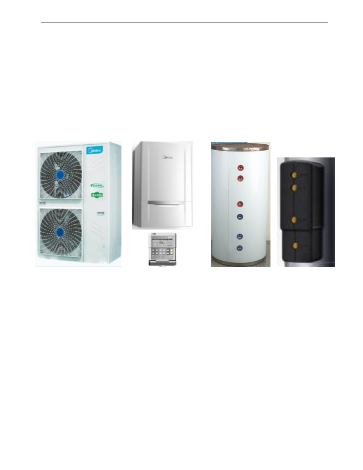
LRSJF-V120/SN1-610
LRSJF-V140/SN1-610
Outdoor unit
LSX-300XP/D15B11
Water tank
SMK-120/CSD80GN1
SMK-140/CSD80GN1
Indoor unit
TMK-01
Solar kit
Page 2

MCAC-RTSM-2012-07 M-thermal Technical Manual(part 1)
2
Part 1
System Outline
1. Measurements ................................................................. 3
2. External Appearance ...................................................... 4
3. Nomenclature .................................................................. 5
4. Features ........................................................................... 7
5. Specifications .................................................................. 9
5.1 Specifications of outdoor units .......................................................... 9
5.2 Specifications of Hydraulic indoor unit .......................................... 10
5.3 Specifications of water tank and solar kit ........................................11
6. Performance data .......................................................... 12
6.1 Heating performance data of 14kw model ...................................... 12
6.2 Cooling performance data of 14kw model ...................................... 12
6.3 Heating performance data of 12kw model ...................................... 13
6.4 Cooling performance data of 12kw model ...................................... 13
7. Wiring Diagrams ........................................................... 14
7.1 Outdoor units wiring diagram .......................................................... 14
7.2 Hydraulic indoor units wiring diagram ............................................ 15
8. Exploded View ............................................................... 16
8.1 Exploded view of outdoor units ....................................................... 16
8.2 Exploded view of hydraulic indoor units ........................................ 18
8.3 Exploded view of water tank ............................................................ 20
8.4 Exploded view of solar kit ................................................................ 22
Page 3
MCAC-RTSM-2012-07 M-thermal Technical Manual(part 1)
3
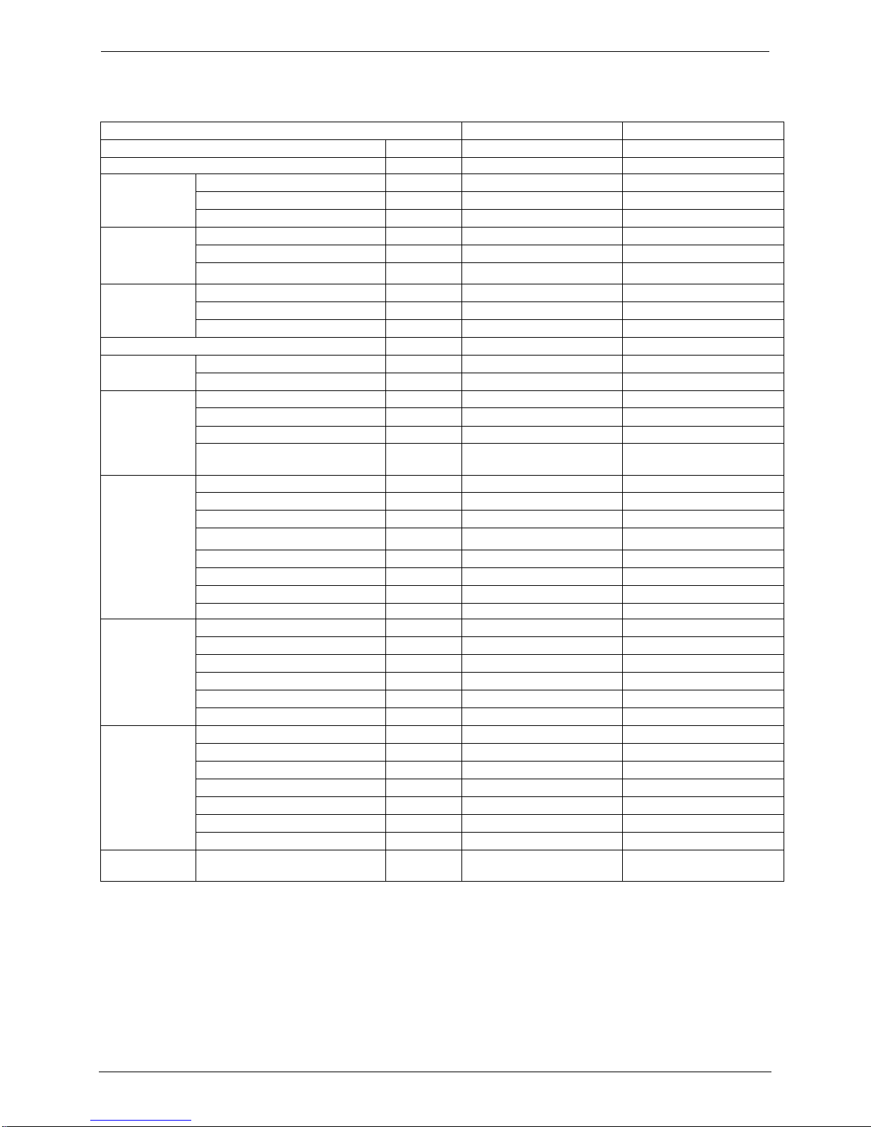
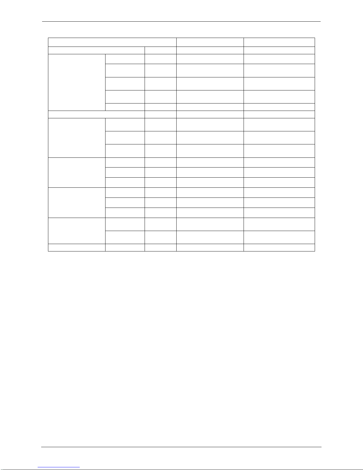
1. Measurements
Outdoor units
Model name
Dimension (mm)
Net/Gross weight (kg)
Power supply
LRSJF-V120/SN1-610
Width: 900
Height: 1327
Depth:348
89/101
380V~415V-50Hz
3 Ph
LRSJF-V140/SN1-610
Hydraulic indoor unit
SMK-120/CSD80GN1
Width: 900
Height:500
Depth:375
63/75
380V~415V-50Hz
3 Ph
SMK-140/CSD80GN1
Solar kit
TMK-01
Width: 810
Height: 310
Depth:295
8/10
220V~240V-50Hz
1 ph
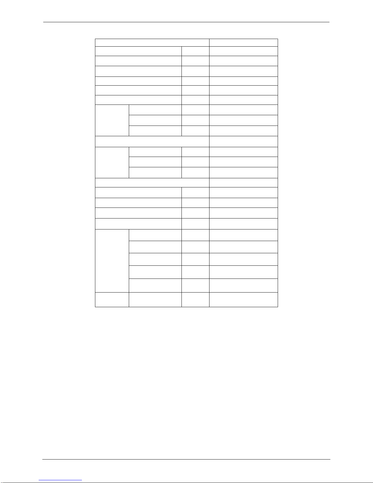
Water Tank
Model name
Dimension (mm)
Net/Gross weight (kg)
Packing Dimension W×D×H
LSX-300XP/D15B11
Ф580×1800
75//84
620×1960×635
Page 4
MCAC-RTSM-2012-07 M-thermal Technical Manual(part 1)
4
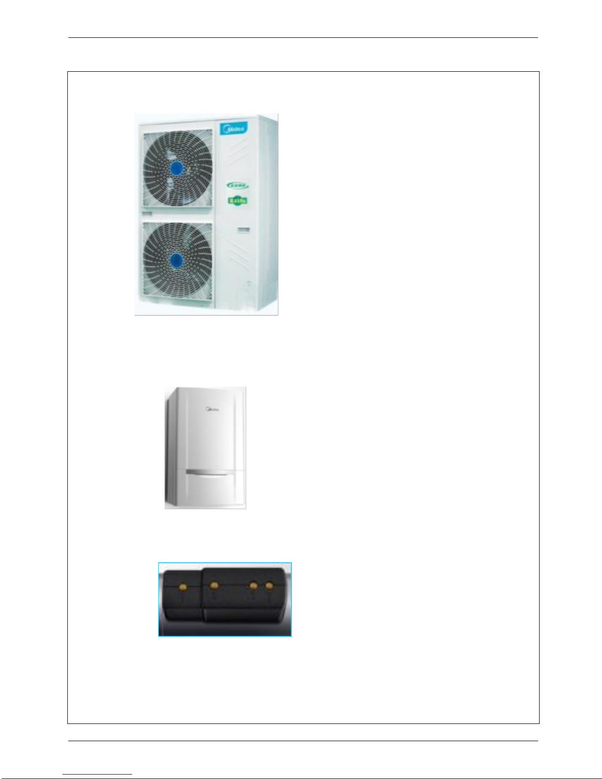
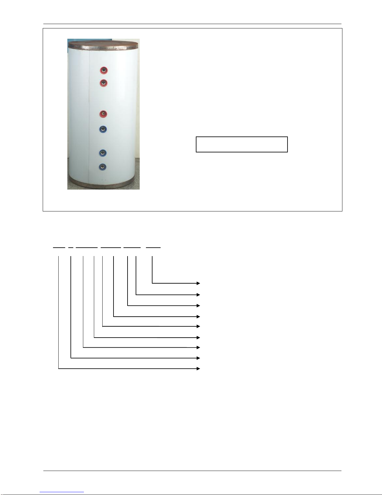
2. External Appearance
LRSJF-V120/SN1-610
LRSJF-V140/SN1-610
SMK-120/CSD80GN1 SMK-140/CSD80GN1
TMK-01
Page 5
MCAC-RTSM-2012-07 M-thermal Technical Manual(part 1)
5
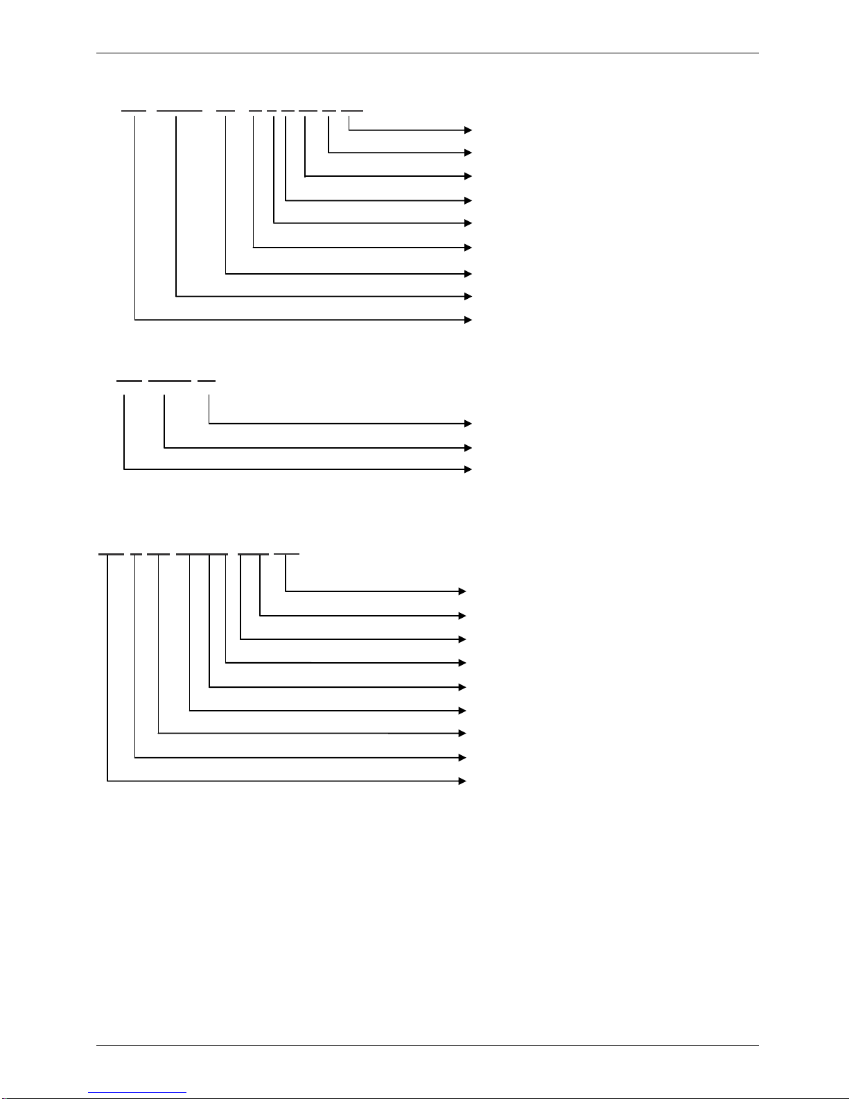
3. Nomenclature
Outdoor unit
CE-L RSJF-V120/SN1- 610
Design code
Refrigerant type (R410a)
380-415V~ 3phase 50Hz
Heating Capacity (12000W)
Compressor type (DC inverter compressor)
Split type
Midea Heat Pump water heater
Heating and cooling mode (Omit for heating)
Export model code
LSX-300XP/D15B11
Page 6
MCAC-RTSM-2012-07 M-thermal Technical Manual(part 1)
6
Indoor unit
CE- SMK – 80 / C S D 80 G N1
Solar kit
CE-TMK-01
CE-L SX-300XP/ D15 B11
Refrigerant type (R410a)
Heating type (Floor heating)
E-heater Capacity (8000W)
Electric heater
Power type (3ph, 380V)
Water cycle type
Heating Capacity (8000w)
Hydraulic modular
Export model code
Design code
Solar heating unit
Export model code
Design code
E-heater power(1500w)
Electric heater
Water tank appearance code (spraying appearance)
Water tank inner tank code (Stainless Steel inner tank )
Water tank volume (300L)
Water tank code
Water tank type code (vertical type)
Export model code
Page 7
MCAC-RTSM-2012-07 M-thermal Technical Manual(part 1)
7
4. Features
4.1 Safety
a. Realize isolation between water and electricity. No electric shock problem, more safety.
b. No fuel tubes and storage, no potential danger from oil leakage, fire, explosion etc. Five operating
mode:
1). Space cooling
2). Space heating
3). Water heating
4). Space cooling + water heating
5). Space heating + water heating
4.2 Environmental friendly.
a. R410a refrigerant;
b. No discharge of poisonous gas;
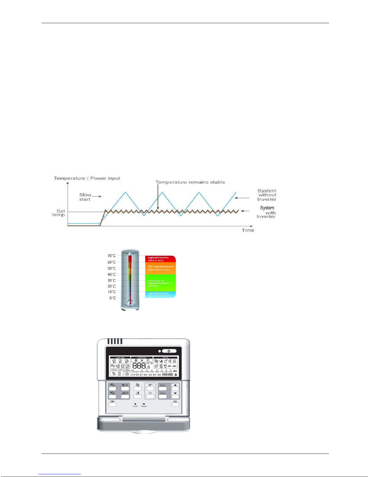
4.3 DC inverter system.
.
4.4 Automatic weekly anti-legionella function
4.5 Easy operation and automatic control.
The system can be controlled simply through the wire controller.
Page 8
MCAC-RTSM-2012-07 M-thermal Technical Manual(part 1)
8
4.6 High efficiency and energy-saving.
The unit adopts heat pump principle, which absorbs heat from outdoor air and produce heat water, thermal
efficiency for water heating be up to 4.3.
4.7 All the weather the system can run.
Within the temperature range from -20 to 43℃, it will not be affected by night, overcast sky, rain and snow.
4.8 Convenient installation and maintenance
The quadrate type can be easily installed in a corner of the verandah even if it’s very narrow.
4.9 Total Heating Solution
When floor heating is conducted in a new house, warm air spreads gently across the house, making it
comfortable and enabling the use of broad space without necessitating radiators or FCU.
4.10 Comfort System
When floor heating is applied, warm air spreads gently across the house, making it comfortable. The system
can help blood circulation and metabolism, further boosting our health.
The installation of M-Thermal will eliminate oil or gas tank, making the household surrounding neat and safe,
enabling the use of more space, and avoiding refueling.
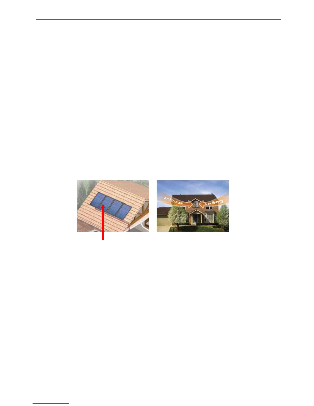
4.11 Reduce CO2 emission
When the system is connected to solar panels, CO2 can be reduced more sharply.
In addition, M-thermal can significantly cut CO
2
emission when being connected to solar thermal panel a
completely pure energy source.
4.12 CE approval
Solar Panel
Page 9
MCAC-RTSM-2012-01 M-thermal Technical Manual
9
5. Specifications
5.1 Specifications of outdoor units
DC Inverter outdoor unit
LRSJF-V120/SN1-610
LRSJF-V140/SN1-610
Power supply
Ph-V-Hz
3-380~415-50
3-380~415-50
Max. current
A 9 9
Heating
Capacity
kW
12
14
COP
kW/kW
4.17
4.13
Ambient Temp.
℃
-20~43
-20~43
Cooling
Capacity
kW
8.8
8.8
COP
kW/kW
2.22
2.28
Ambient Temp.
℃
15~43
15~43
Unit
Dimension (W×H×D)
mm
900×1327×320
900×1327×320
Packing (W×H×D)
mm
1016×1456×435
1016×1456×435
Net/gross weight
kg
89/101
89/101
Noise level
dB(A)
58
58
Refrigerant
type/quantity
kg
R410a/2.7kg
R410a/2.7kg
system pressure
MPa
4.4/2.6
4.4/2.6
Refrigerant
pipe
Liquid side
mm
Ф9.52
Ф9.52
Gas side
mm
Ф16
Ф16
Max. length
m
50
50
Max. difference between
outdoor unit and indoor unit
m
15
15
Compressor
Model
TNB306FPNMC
TNB306FPNMC
Type
Rotary
Rotary
Brand
Mitsubishi
Mitsubishi
Capacity
kW
9.88
9.88
Input
w
3010
3010
Locked rotor current
A
45
45
Rate current
A
9.3
9.3
Crankcase
W
30
30
Fan motor
Brand
Panasonic
Panasonic
Model
WZDK100-38G(×2)
WZDK100-38G(×2)
Type
DC MOTOR
DC MOTOR
Input
w
100*2
100*2
Output
w
110*2
110*2
Speed
r/min
800
800
Outdoor coil
Number of rows
2 2
Tube pitch(a)x row pitch(b)
mm
25.4/22
25.4/22
Tube dia. and type
mm
7.94(female screw)
7.94(female screw)
Fin space
mm
1.7
1.6
Fin type (code)
Hydrophilic aluminum
Hydrophilic aluminum
Coil length x height
1276*870
1276*870
Number of circuits
7 7
Loading
Quantity
20'/40'/40H
Pcs
28/58/58
28/58/58
Page 10
MCAC-RTSM-2012-01 M-thermal Technical Manual
10
5.2 Specifications of Hydraulic indoor unit
Hydraulic indoor unit
SMK-120/CSD80GN1
SMK-140/CSD80GN1
Power supply
Ph-V-Hz
3-380~415-50
3-380~415-50
Function
Types
Heating &Cooling
Heating &Cooling
Space
Heating
℃
15~55
15~55
Space
Cooling
℃
7~22
7~22
Sanitary Hot
Water
℃
35~60
35~60
Max. current
A
13.8
13.8
Noise level
dB(A)
32
32
Unit
Dimension
(W×H×D)
mm
900×500×375
900×500×375
Packing
(W×H×D)
mm
1110×610×510
1110×610×510
Net/gross
weight
kg
63/75
63/75
E-heater
Size
kW
4 4 Quantity
1 1 specification
Ph-V
3-400
3-400
E-heater(standby)
Size
kW
4 4 Quantity
1
1
specification
Ph-V
3-400
3-400
Water pipeline
Water inlet
pipe
mm
DN32
DN32
Water outlet
pipe
mm
DN32
DN32
Loading Quantity
20'/40'/40H
Pcs
66/138/184
66/138/184
The testing Condition:
1. Heating: Outdoor temp. 7/6℃(DB/WB), inlet water temp. 30℃, outlet water temp. 35℃.
2. Cooling: Outdoor temp. 35/24℃(DB/WB), inlet water temp. 12℃, outlet water temp. 7℃.
Page 11
MCAC-RTSM-2012-01 M-thermal Technical Manual
11
5.3 Specifications of water tank and solar kit
Sanitary hot water tank
LSX-300XP/D15B11
Power supply
Ph-V-Hz
1-220~240-50
Storage size
L
300
Max. water output temp.
℃
60
Dimension (D×H)
mm
Ф580×1800
Packing (W×H×D)
mm
670×1885×670
Net//gross weight
kg
80/91
E-heater
specification
kW
1.5
Quantity
1
Power supply
Ph-V
1-220~240-50
Tank material
SUS304
Water
pipeline
Water inlet pipe
mm
DN20
Water outlet pipe
mm
DN20
PT valve joint
MPa
DN20
Solar kit
TMK-01
Power supply
Ph-V-Hz
1-220~240-50
Dimension (W×H×D)
mm
810×310×295
Packing (W×H×D)
mm
830×340×315
Net weight
kg
8/10
solar coils
OD+T
mm*mm
¢22*0.8
Length
m
11
Material
SUS316L
Inlet pipe
mm
DN20
Outlet pipe
mm
DN20
Loading
Quantity
20'/40'/40H
Pcs
300/624/728
Page 12
MCAC-RTSM-2012-01 M-thermal Technical Manual
12
6. Performance data
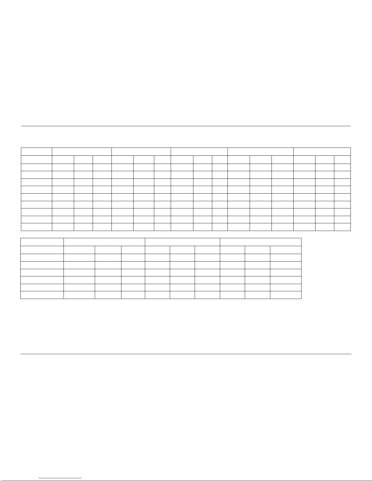
6.1 Heating performance data of 14kw model
LWE[℃]
25
32
40
43
50
Tamb [℃]
HC[W]
PI[W]
COP
HC[W]
PI[W]
COP
HC[W]
PI[W]
COP
HC[W]
PI[W]
COP
HC[W]
PI[W]
COP
-20
4850
1725
2.81
3511
1887
1.53 / / / / / / / /
/
-10
6943.5
2471
2.81
6426
2758
2.33
5476
3094
1.77
5120
3220
1.59 / /
/
-5
10555
3586
2.94
8935
3327
2.69
7804
3722
2.1
7391
3883
1.9 / /
/
0
9138
3662
2.5
11254
4115
2.73
10101
4353
2.32
9317
4274
2.18 / /
/
2/1
12614
3835
3.29
13017
4244
3.07
10882
4410
2.47
9922
4369
2.27 / / / 7/6
15601
3851
4.05
14871
4251
3.5
13036
4472
2.92
11897
4410
2.7
6531
3293
1.98
15/12
17258
3629
4.76
17077
4046
4.22
14503
4003
3.62
13969
4205
3.32
7162
2676
2.68
25/17
13570
2331
5.82
14152
2640
5.36
11336
2573
4.41
7696
2288
3.36
6299
2029
3.1
35/24
/ / / / / / 13060
2769
4.72
10902
2530
4.31
6059
1781
3.4
6.2 Cooling performance data of 14kw model
Remark:
CC= cooling capacity PI = power input HC = heating capacity
LWE[℃]
10
15
20
Tamb [℃]
CC[W]
PI[W]
EER
CC[W]
PI[W]
EER
CC[W]
PI[W]
EER
15
4120
1289
3.2 / / / / / /
20
5122
1378
3.72
11441
2980
3.84 / /
/
25
5584
1450
3.85
12009
3217
3.73
14153
3587
3.95
30
5468
1608
3.41
11349
3504
3.24
13596
3504
3.88
35
5463
2110
2.59
10264
3836
2.68
12326
4272
2.89
43
5922
3259
1.82
7357
3365
2.19
8853
3450
2.57
Page 13
MCAC-RTSM-2012-01 M-thermal Technical Manual
13
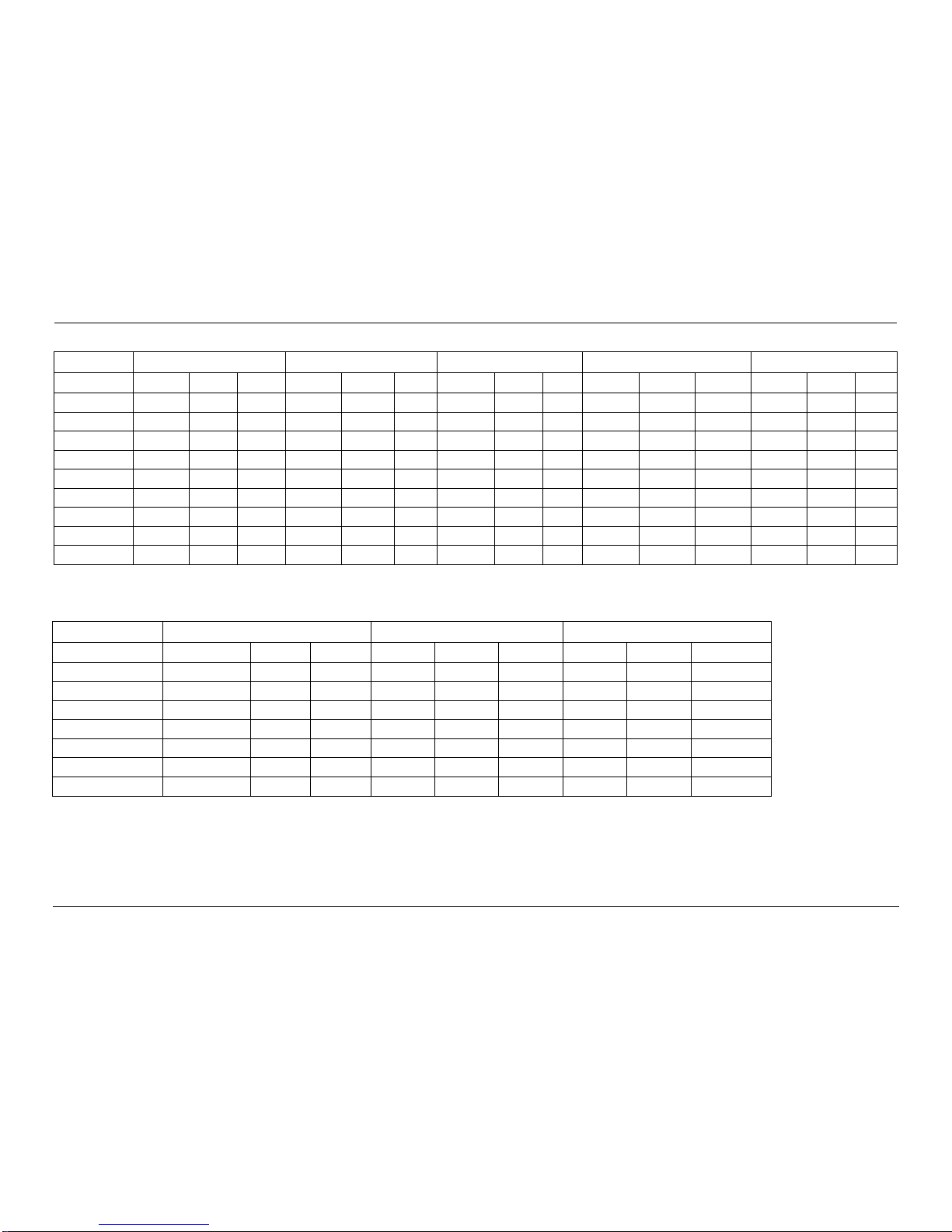
6.3 Heating performance data of 12kw model
LWE[℃]
25
32
40
43
50
Tamb [℃]
HC[W]
PI[W]
COP
HC[W]
PI[W]
COP
HC[W]
PI[W]
COP
HC[W]
PI[W]
COP
HC[W]
PI[W]
COP
-20
2883
1749
1.65
2453
1891
1.30 / / / / / / / /
/
-10
7090
2481
2.86
6656
2772
2.40
5514
3107
1.77
4721
3230
1.46 / /
/
-5
9652
3030
3.19
9234
3344
2.76
8498
3750
2.27
7819
3908
2.00 / /
/ 0 5662
2951
1.92
10921
3949
2.77
10277
4363
2.36
9267
4311
2.15
6433
3578
1.80
2/1
11208
3388
3.31
10601
3641
2.91
9432
3768
2.50
9177
4030
2.28
8272
4078
2.03
7/6
14824
3677
4.03
14241
4049
3.52
11589
3978
2.91
11257
4171
2.70
5731
3015
1.90
15/12
17436
3682
4.74
17029
4100
4.15
14311
4056
3.53
13508
4226
3.20
6872
2618
2.62
25/17
13181
2133
6.18
13412
2436
5.51
11683
2457
4.75
10320
2365
4.36
6299
2029
3.10
35/24
/ / / / /
/
11683
2432
4.80
9770
2333
4.19
6748
2031
3.32
6.4 Cooling performance data of 12kw model
Remark:
CC= cooling capacity PI = power input HC = heating capacity
LWE[℃]
10
15
20
Tamb [℃]
CC[W]
PI[W]
EER
CC[W]
PI[W]
EER
CC[W]
PI[W]
EER
15
4199
1308
3.21 / / / / / /
20
6960
1781
3.91
9973
2732
3.65 / /
/
25
7908
2355
3.36
11272
2969
3.8
12878
3018
4.27
30
7752
3064
2.53
10532
3253
3.24
12453
3322
3.75
35
10252
3629
2.82
12494
3753
3.33
15884
4233
3.75
40
7039
2812
2.5
9537
3550
2.69
11506
3663
3.14
43
5814
3251
1.79
7237
3350
2.16
8693
3445
2.52
Page 14
MCAC-RTSM-2009-09 Midea Heat Pump Water Heater Technical Manual
14
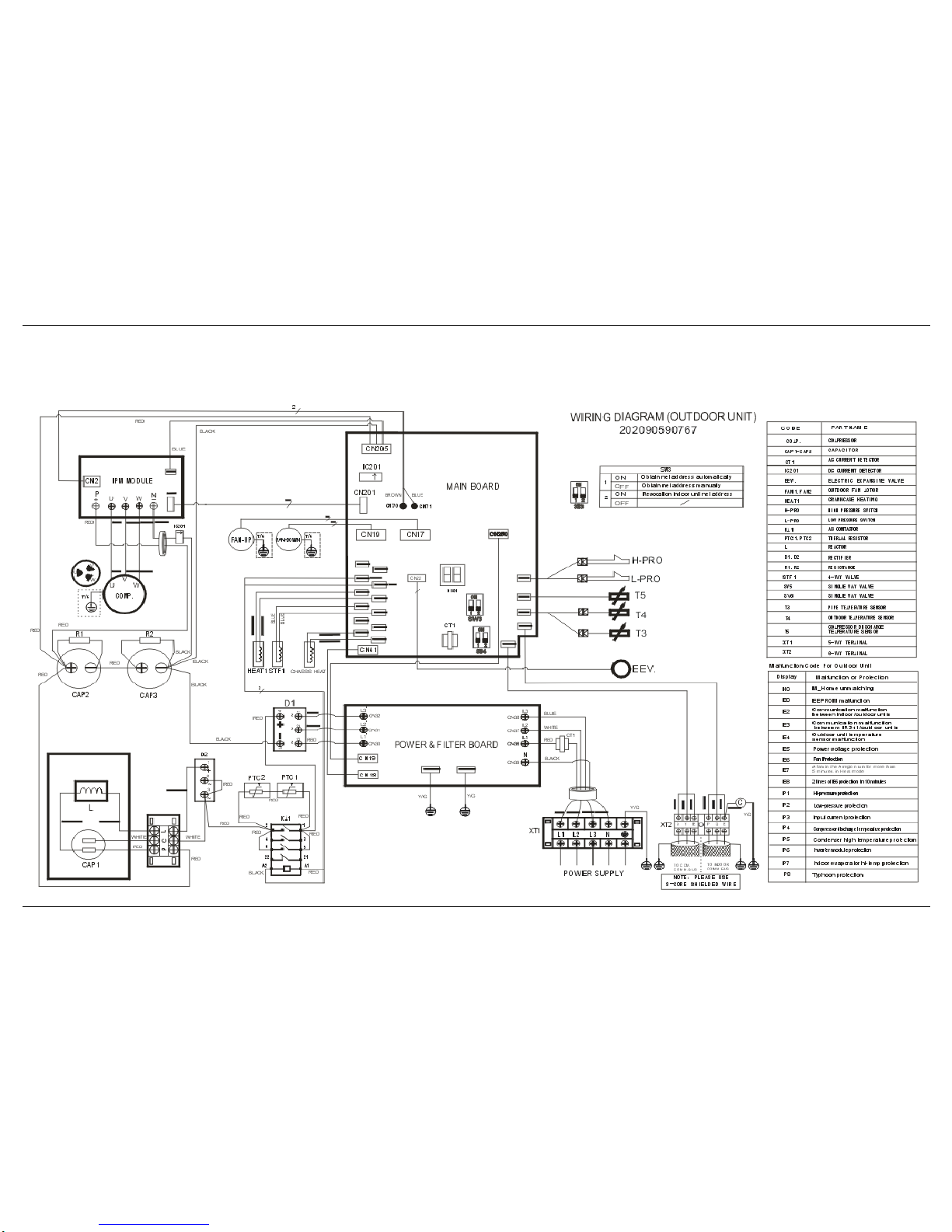
7. Wiring Diagrams
7.1 Outdoor units wiring diagram
Model:CE-LRSJF-V120/SN1-610 CE-LRSJF-V140/SN1-610
Page 15
MCAC-RTSM-2009-09 Midea Heat Pump Water Heater Technical Manual
15
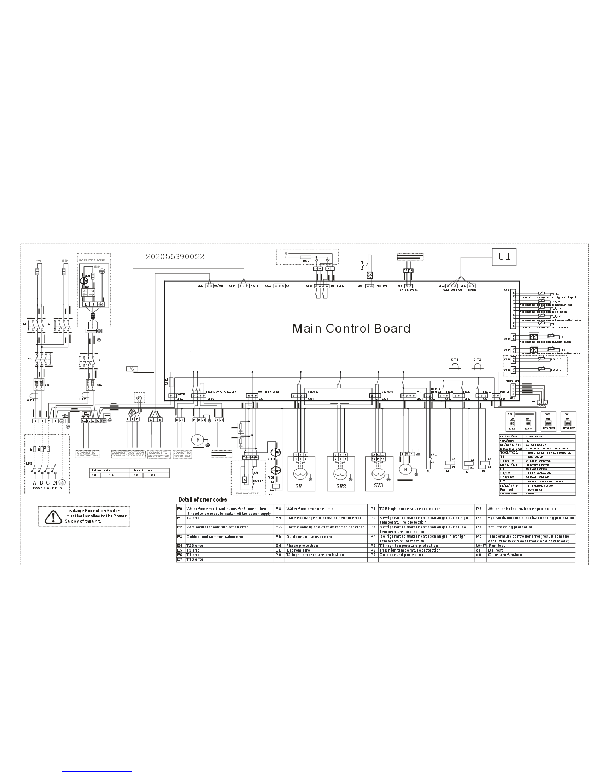
7.2 Hydraulic indoor units wiring diagram
Model :SMK-120/CSD80GN1 SMK-140/CSD80GN1
Page 16
MCAC-RTSM-2009-09 Midea Heat Pump Water Heater Technical Manual
16
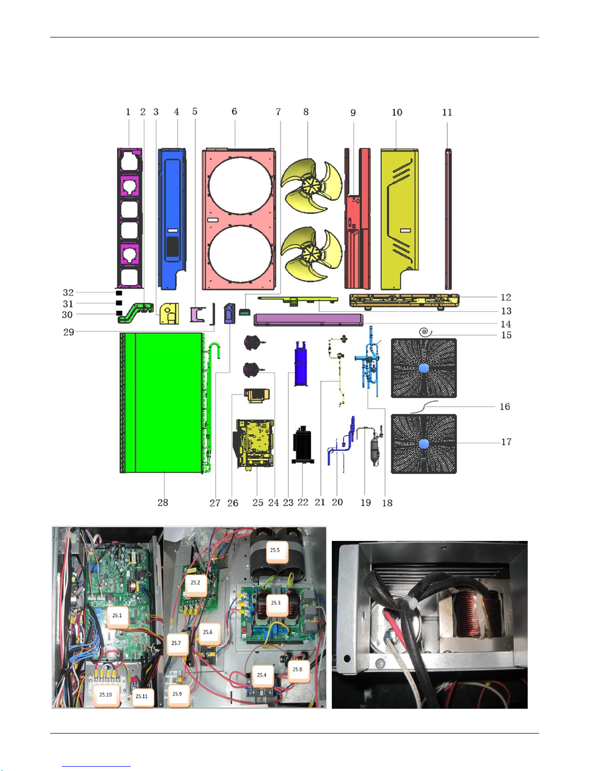
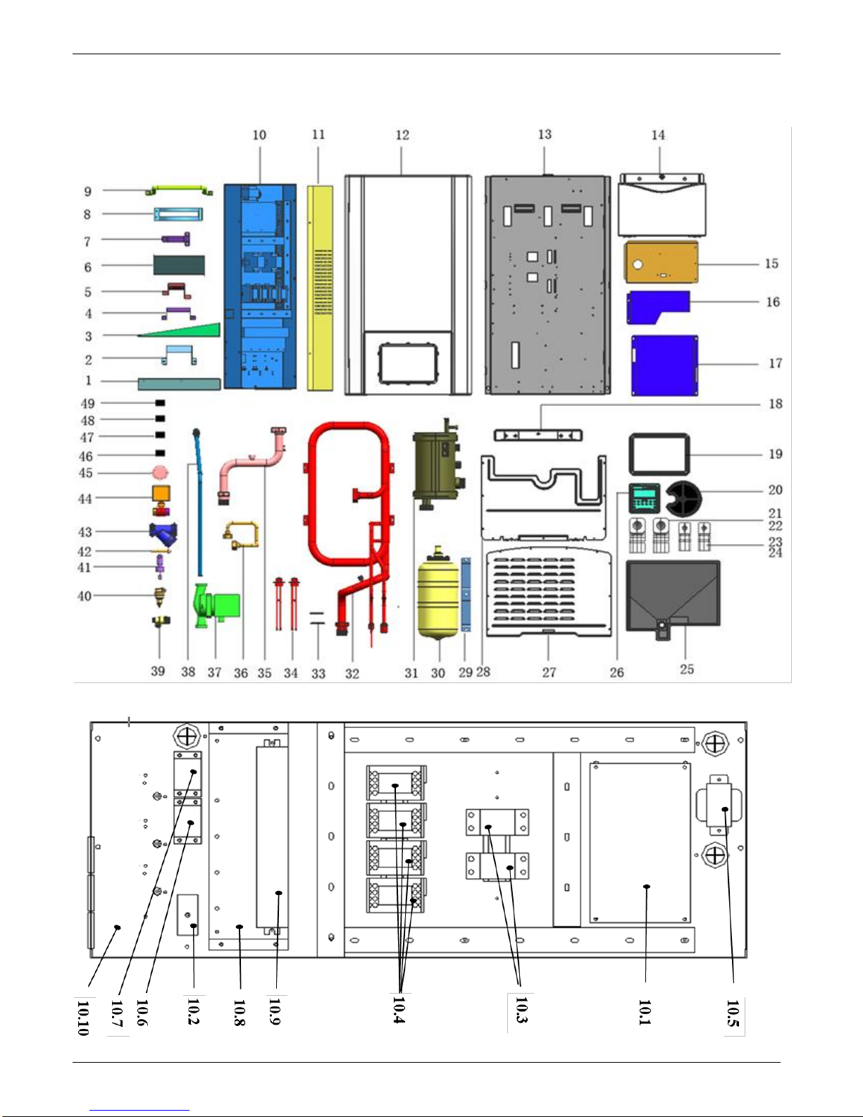
8. Exploded View
8.1 Exploded view of outdoor units
Model: CE-LRSJF-V120/SN1-610 CE-LRSJF-V140/SN1-610
Page 17
MCAC-RTSM-2009-09 Midea Heat Pump Water Heater Technical Manual
17
No.
Part Name
Quantity
BOM code
1
Motor bracket assembly
1
201295190080
2
Valve mounting plate
1
201295190083
3
Cover before the tube
1
201295190086
4
Right rear side
1
201295190081
5
Installation of gas-liquid separator plate
1
201295190079
6
Front Panel
1
201295190088
7
Handle
3
201195190001
8
Axial fan
2
201100300524
9
Partition components
1
201295190094
10
Right front side components
1
201295190082
11
Left rear support
1
201295190084
12
Base
1
201295190174
13
Layering fence
1
201295190076
14
Cover parts
1
201295190089
15
Compressor electric heater
1
202403100155
16
Electric heater
1
202403101687
17
Net
2
201195190163
18
Four-way valve parts
1
201695190355
19
Discharge pipe ass'y
1
201695190460
20
Suction pipe ass'y
1
201690590359
21
Electronic expansion valve ass'y
1
201690590595
22
Compressor
1
201401500270
23
Gas-liquid separator
1
201601100084
24
DC Motor
2
202400300216
25
E-part box ass'y
1
203390590094
25.1
Main control board ass'y
1
201390590073
25.2
Inverter module
1
201319902223
25.3
outdoor unit power supply board
1
201395190184
25.4
AC contactor
1
202300850054
25.5
Aluminum electrolytic capacitor
2
202300300109
25.6
Three phase bridge
1
202300500348
25.7
Single-phase bridge
1
202300500910
25.8
Resistance
2
202300130008
25.9
Wire joint
1
202301450115
25.10
Wire joint
1
202301450133
25.11
Six Terminal Block
1
202301400242
26
Electrical inductance Ass'y
1
203395100212
26.1
Compressor capacitor
1
202401090058
26.2
inductance
1
202301000927
27
After the tube cover
1
201295190085
28
Condenser ass'y
1
201595190036
29
Transport to strengthen board
1
201295190078
30
Discharge temp sensor ass'y
1
202301300124
31
room temp sensor ass'y
1
202301300197
32
Outdoor coil temp sensor ass'y
1
202301300438
Page 18
MCAC-RTSM-2009-09 Midea Heat Pump Water Heater Technical Manual
18
8.2 Exploded view of hydraulic indoor units
Model :SMK-120/CSD80GN1 SMK-140/CSD80GN1
Page 19
MCAC-RTSM-2009-09 Midea Heat Pump Water Heater Technical Manual
19
No.
Part Name
Quantity
BOM code
No.
Part Name
Quantity
BOM code
1
Electronic control
box mounting plate
2
1
201256390012
21
Right foam refrigerant
pipe
2
202256390004
2
Pump mounting
plate
1
201256390014
22
Left foam refrigerant
pipe
2
202256390005
3
1 electronic control
box mounting plate
1
201256390013
23
Right out of the
bubble pipe
2
202256390002
4
Refrigerant pipe
fixed plate
1
201256390008
24
Left out of the bubble
pipe
2
202256390003
5
Fixed plate inlet
1
201256390009
25
Water tray
components
1
202256390001
6
Pump Bracket 2
1
201256390004
26
Hydraulic module
wired remote
1
203355100567
7
Outlet pipe fixed
plate
1
201256390010
27
Roof
1
201256390033
8
Expansion tank
clamp
1
201290490010
28
Bottom
1
201256390034
9
Handle
1
201256390011
29
Mounting Bracket
1
201256390017
10
E-part box ass'y
1
203356390006
30
Expansion Tank
1
201601300552
10.1
Main controller
ass'y
1
201356390008
31
Small water tank
1
201256390006
10.2
Wire joint, 6p
1
202301400219
32
Casing components
1
201756390001
10.3
32A MCB
2
202301620210
33
Shaft
2
201256390035
10.4
AC contactor
4
202300850054
34
Electric heater
2
202403101682
10.5
Transformer
1
202300900109
35
Outlet pipe
components
1
201656390016
10.6
Wire joint, 5p
1
202301450039
36
Expansion Tank take
over the components
1
201656390014
10.7
Wire joint
1
202301450133
37
Drain Pump
1
202400600085
10.8
Electronic control
box terminal strip
bracket
1
201256390001
38
Connect hose
1
201119900833
10.9
Thirty Terminal
Block
1
202301400244
39
Safety valve
1
201604100106
10.10
E-part box ass'y
1
201256390036
40
Exhaust valve
1
201601601296
11
Electronic control
box cover
1
201256390003
41
Target Flow Switch
1
202301800869
12
Front Panel
1
201256390031
42
Expansion bolt
assembly
5
202501100838
13
Rear
1
201256300023
43
Electric valve
3
201601601255
14
Flip
1
201256390032
44
Y Type filter
1
201695700020
15
Wired remote
support
1
201256390018
45
Hydraulic meter
1
201800100005
16
Pump bracket
1
201256390015
46
Temp sensor
1
202301300311
17
Small water tank
fixed plate
1
201256390016
47
Pipe temperature
sensor assemblies
1
202301300494
18
Decorative plates
1
201156390003
48
Temp sensor ass'y
1
202301300495
19
Decorative ring
1
201156390004
49
Thermostat
components
1
202456390020
20
Electric heating
cover
1
201156390002
Page 20
MCAC-RTSM-2009-09 Midea Heat Pump Water Heater Technical Manual
20
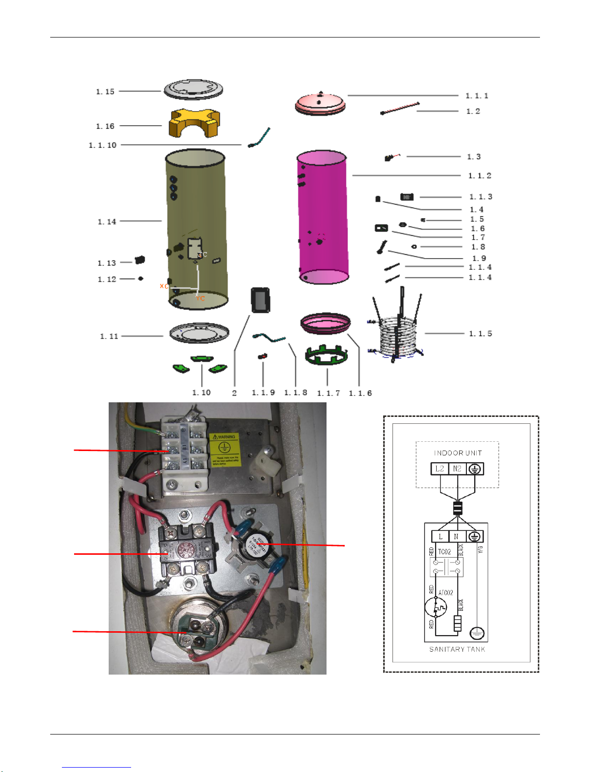
8.3 Exploded view of water tank
1.5
1.4
1.6
1.9
Page 21
MCAC-RTSM-2009-09 Midea Heat Pump Water Heater Technical Manual
21
No.
Part Name
Quantity
BOM code
1
Water tank foam components
1
201256190027
1.1
Liner welded components
1
201256190023
1.1.1
Head on liner
1
201256100529
1.1.2
Inner barrel body
1
P0000805371
1.1.3
Terminal Block Bracket
1
201256190025
1.1.4
Temperature control components Ⅱ
2
P0000613681
1.1.5
Solar coil assembly
1
201256190019
1.1.6
Under the head liner
1
201256190024
1.1.7
Interior support frame
1
201290590109
1.1.8
Inlet components
1
P0000613631
1.1.9
Drainage fittings
1
201290590138
1.1.10
Outlet pipe components
1
P0000613665
1.2
Magnesium anode
1
202990590003
1.3
TP relief valve
1
201601601206
1.4
Three Terminal Block
1
202301400246
1.5
Thermometer
1
202301600046
1.6
Temp sensor
1
202301610028
1.7
Stator of temp. sensor
1
201290590034
1.8
seal ring of radiation pipe
1
202790590001
1.9
Electric heating pipe water
1
202403100092
1.10
Plastic foot
3
201190500293
1.11
Tank bottom
1
P0000805356
1.12
Coil rubber too
1
202790500510
1.13
Water tank handle
2
201156100038
1.14
Shell
1
P0000805335
1.15
Tank cover
1
P0000805345
1.16
Top foam liner
1
202256190001
2
Heater Cover
1
201256190015 3 Wiring nameplate
1
202056190049
Page 22
MCAC-RTSM-2009-09 Midea Heat Pump Water Heater Technical Manual
22
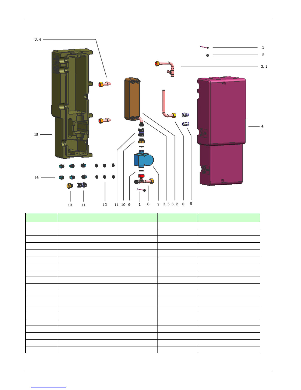
8.4 Exploded view of solar kit
No.
Part Name
Quantity
BOM code
1
Cross Recess Head Screw
2
202500300859
2
washers
2
202502100091
3
plate exchanger ass'y
1
201756390002
3.1
plate exchanger outlet pipe ass'y
1
201656390002
3.2
plate exchanger
1
201700101111
3.3
plate exchanger inlet pipe ass'y
1
201656390005
3.4
plate exchanger inlet/outlet pipe
2
201656390001
4
right foam
1
202656390002
5
adapter
2
201600401064
6
connecting pipe
1
201656390004
7
Shield pump ass'y
1
202400600073
8
pump connecting tube components
1
201656390010
9
seal ring
2
202795700050
10
non-return valve joint II
1
201656390008
11
non-return valve
2
201656390007
12
seal ring
6
202790500050
13
non-return valve joint IV
1
201656390009
14
Seal Stopper
6
201170390002
15
left foam
1
202656390001
Page 23

Part 2 Installation
1. Outdoor unit installation ............................................ 2
2. Hydraulic modular unit installation ......................... 12
3. Installation of the solar kit ....................................... 18
4. Installation of sanitary water tank ........................... 22
5 Filed wiring................................................................ 27
Page 24
1. Outdoor unit installation
1.1 Precaution
1) Ensure that all Local, National and International regulations are satisfied.
2) Read the ”Installation manual” carefully before Installation.
3) The precautions described below include the important items regarding safety. Observe them
without fail.
4) After the installation work, perform a trial operation to check for any problem.
4) Follow the Owner’s Manual to explain how to use and maintain the unit to the customer.
5) Turn off the main power supply switch (or breaker) before the unit maintenance.
6) Ask the customer to keep the Installation Manual together with the Owner’s Manual.
7) Some tools as follow table should be prepared before installation:
1
Philips screw driver
12
Hexagonal wrench
2
Hole core drill(65mm)
13
Pipe flaring tool
3
Spanner
14
Pipe bender
4
Pipe cutter
15
Level vial
5
Knife
16
Metal saw
6
Reamer
17
Manifold gauge (Charge hose:R410A special requirement)
7
Gas leak detector
18
Vacuum pump (Charge hose:R410A special requirement)
8
Tape measure
19
Torque wrench 1/4(17mm)16N•m (1.6kgf•m),
3/8(22mm)42N•m (4.2kgf•m), 1/2(26mm)55N•m (5.5kgf•m)
5/8(15.9mm)120N•m(12.0kgf•m)
9
Thermometer
20
Copper pipe gauge adjusting projection margin
Page 25
10
Mega-tester
21
Vacuum pump adapter
11
Electro circuit tester
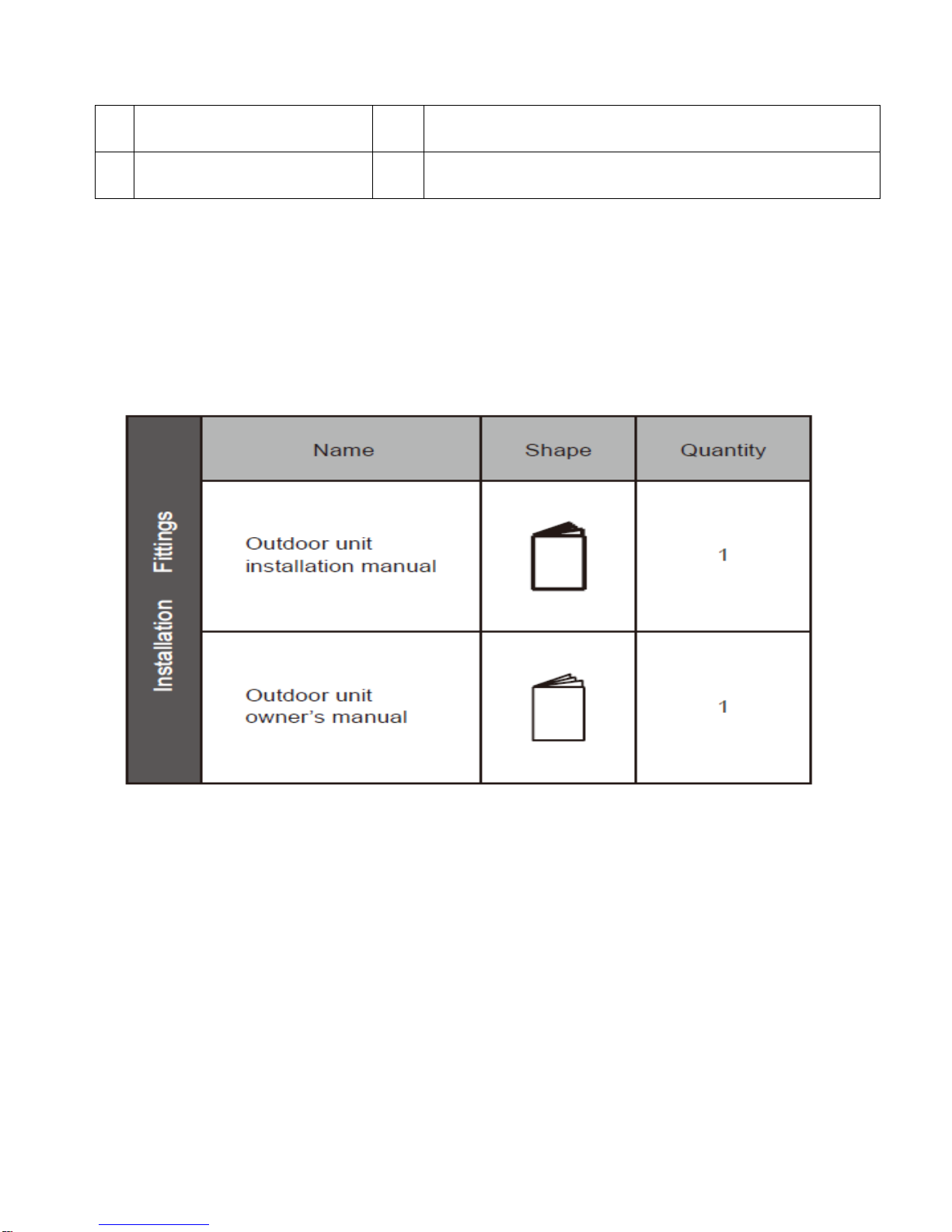
1.2 Accessory
Please check whether the following fittings are of full scopes. If there are some spare fittings ,
please restore them carefully.
1.3 Installation place
Please keep away from the following place, or malfunction of the machine may be
caused:
1) There is combustible gas leakage.
2) There is much oil (including engine oil) ingredient.
3) There is salty air surrounding (near the coast)
4) There is caustic gas (the sulfide, for example) existing in the air (near a hot spring)
5) A place the heat air expelled out from the outdoor unit can reach
Page 26

your neighbor’s window.
6) A place where the drain water may make problems.
7) A place that the noise interferes your neighbors everyday life.
8) A place that is exposed to a strong wind.
9) A place that is too weak to bear the weight of the unit.
10) A place that block a passage.
11) Uneven place.
12) Insufficient ventilation place.
13) Near a private power station or high frequency equipment.
Caution:
When an outdoor unit is installed in a place that is always exposed to a strong wind like a
coast or on a high storey of a building, secure a normal fan operation by using a duct or a wind
shield.
When the outdoor unit is installed in an elevated position be sure to secure its feet.
Keep indoor unit, outdoor unit, power supply wiring and transmission wiring at least 1 meter
away from televisions and radios. This is to prevent image interference and noise in those
electrical appliances. (Noise may be generated depending on the conditions under which the
electric wave is generated, even if 1 meter is kept.)
The insulation of the metal parts of the building and the heater pump should comply with the
regulation of National Electric Standard.
Page 27
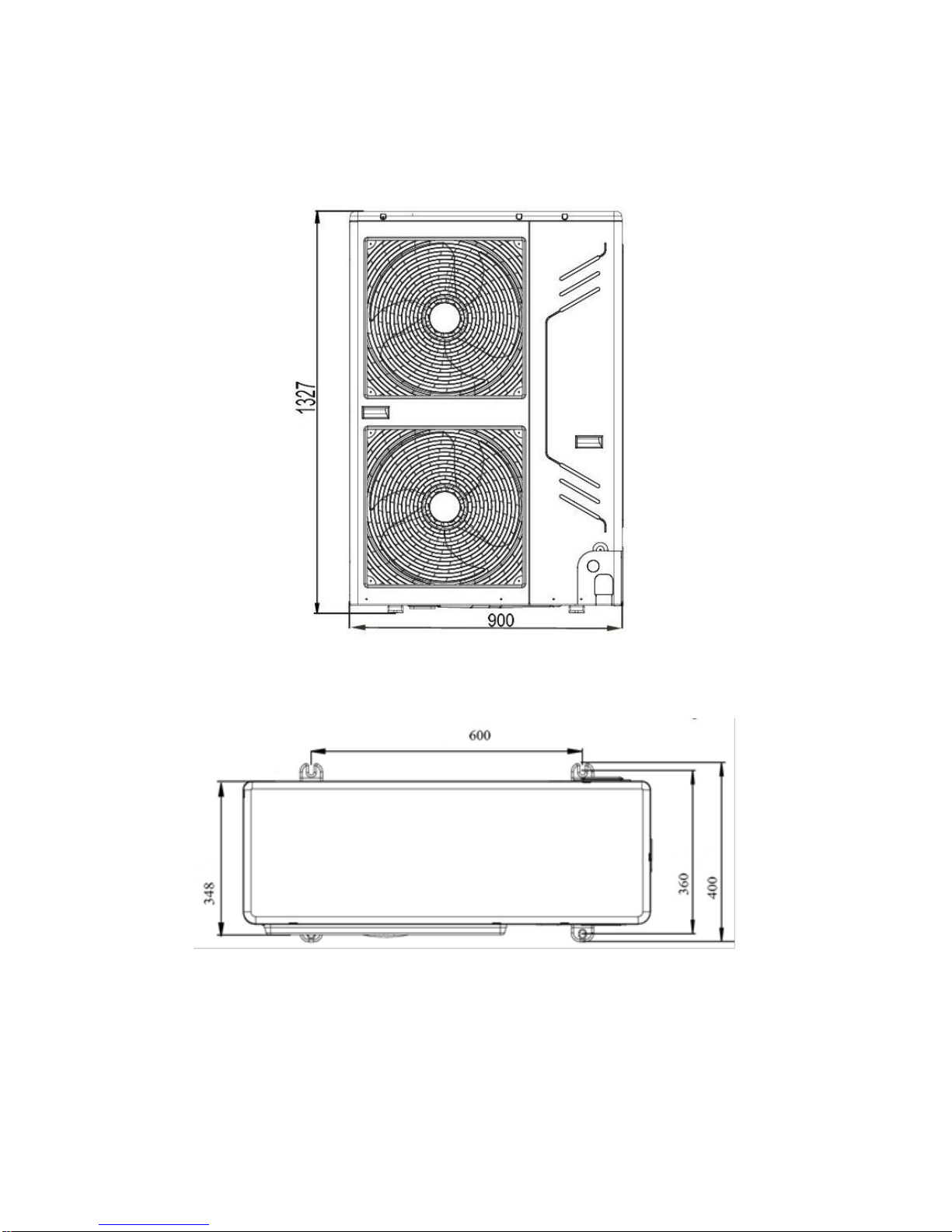
1.4 Dimensions of the outdoor unit
1.5 Installation space
1) Single unit installation
Page 28

2) Parallel connect the two units or above
3) Parallel connect the front with rear sides
Page 29

1.6 Moving and installation
1) Since the gravity center of the unit is not at its physical center, so please be careful when
lifting it with a sling.
2) Never hold the inlet of the outdoor unit to prevent it from deforming.
3) Do not touch the fan with hands or other objects.
4) Do not lean it more than 45°, and do not lay it sidelong.
5) Make concrete foundation according to the specifications of the outdoor units.
6) Fasten the feet of this unit with bolts firmly to prevent it from collapsing in case of
earthquake or strong wind. (Refer to follow fig.)
1.7 Water Outlet
Page 30

Caution:
While installing the outdoor unit, pay attention to the installation place and the drainage
pattern; if it’s installed at the alpine zone, the frozen condensed water will block up the water
outlet, please pull out the rubber stopper of the reserve water outlet. If that still fails to satisfy
for the water draining, please knock open the other two water outlets, and keep the water can
drain in time.
Pay attention to the knock the reserve water outlet from outside to inside, and it will be beyond
repair after knocking open, please pay attention to the installation place, lest cause the
inconvenience. Please do the moth proofing for the knocked out hole, to avoid the pest
processing into and destroy the components.
1.8 Pipe connection
1) Check whether the height drop between the indoor unit and outdoor unit, the length of
refrigerant pipe, and the number of the bends meet the following requirements:
Model
The max height drop(m)
The length of
refrigerant pipe(m)
When outdoor unit
is top
When outdoor
unit is bottom
LRSJF-V120/SN1-610
15
10
50
LRSJF-V140/SN1-610
15
10
50
Model
Gas side/Connection type
Liquid side/ Connection type
LRSJF-V120/SN1-610
LRSJF-V140/SN1-610
Φ15.9/ Flaring
Φ9.5/ Flaring
Page 31

Indoor unit
Φ15.9/ Flaring
Φ9.5/ Flaring
2) Refrigerant piping heat Insulation
Do the heat insulation to the pipes of gas side and liquid side separately. The temperature of
the pipes of gas side and liquid side when cooling, for avoiding condensation please do the
heat insulation fully.
1) The gas side pipe should use closed cell foamed insulation material, which the fire-retardant
is B1 grade and the heat resistance over 120℃.
2) When the external diameter of copper pipe≤Φ12.7mm, the thickness of the insulating layer
at least more than 15mm;
When the external diameter of copper pipe≥Φ15.9mm, the thickness of the insulating layer at
least more than 20mm.
3) Please use attached heat-insulating materials do the heat insulation without clearance for
the connecting parts of the indoor unit pipes.
3) Refrigerant piping connection
We should wash the pipes with high pressure nitrogen, never use refrigerant of the outdoor
units. Make sure there is no dirt or water in the pipes before connecting the pipes to the
outdoor units.
Caution:
● Please pay attention to avoid the components where it is connecting to the connecting
pipes.
● To prevent the refrigerant piping from oxidizing inside when welding, it is necessary to
Page 32

charge nitrogen, or oxide will chock the circulation system.
The indoor and outdoor connecting pipe interface and power line outlet. Can select various piping
and wiring patterns such as out from the front, the back, the side and undersurface etc.(The follow
display the locations of several piping and wiring knock-off interfaces)
Caution:
● Side out pipe: please remove the L-shape metal plate, otherwise can not wiring.
● Back out pipe:
Undersurface outlet pipe: the knock out should from inside to outside, and then piping and wiring
through this. Pay attention to the piping, the fat connecting pipe should out from the largest hole,
otherwise the pipes will be rubbed. Please do the moth proofing for the knocked out hole, to
avoid the pest processing into and destroy the components.
● Please wipe off the piping support rubber blanket beside the inner outlet pipe cover of the
machine while back side getting out pipes.
1.9 Airtight Test
Page 33

When we have connected the refrigerant pipe as follows diagram, we should do airtight test to
check whether the system is leakage.
Caution:
● Pressured nitrogen [ 4.3MPa (44kg/cm2 ) for R410A] should be used in the airtight test.
● Tighten high pressure/low pressure valves before applying pressured nitrogen.
● Apply pressure from air vent mouth on the high pressure/low pressure valves.
● The high pressure/low pressure valves are closed when applying pressured nitrogen.
● The airtight test should never use any oxygen, flammable gas or poisonous gas.
1.10 Air Purge With Vacuum Pump
After the airtight test, we should remove the air in the refrigerant connecting pipes.
1) Using vacuum pump to do the vacuum, never using refrigerant to expel the air.
2) Vacuuming should be done from both liquid side and gas side simultaneously.
3) The system should be vacuumized until the vacuum pump indicates the pressure of the pipes
less than 10pa.
1.11 Refrigerant Amount To Be Added
Calculate the added refrigerant according to the diameter and the length of the liquid side pipe
of the outdoor unit/indoor unit connection. If the length of the liquid side pipe is less than 5
meters it is no need to add more refrigerant, so than calculating the added refrigerant the length
of the liquid side pipe must subtract 5 meters.
Page 34

2. Hydraulic modular unit installation
2.1 Accessory
Please check whether the following fittings are of full scopes. If there are some spare fittings ,
please restore them carefully.
Hydraulic
Indoor
Unit
Accessories
Owner's & Installation
Manual
1
Mounting bracket
1
Two-way valve
3
M4 screws
2
Water tank temperature sensor
1
Y-sharp filter
1
Floor heating inlet
temperature sensor, T1B
1
Drain pan kit
1
M8 expansion screws
5
2.2 Installation place
Selecting an installation location
The indoor unit is to be wall mounted in an indoor location that meets the following
requirements:
The installation location is frost-free.
The space around the unit is adequate for serving.
The space around the unit allows for sufficient air circulation.
There is a provision for condensate drain and pressure relief valve blow-off.
Caution:
When the unit running in the cooling mode, Condensate may drop from the water inlet and
water outlet pipes to your furniture and other devices. Please make sure the dropping
condensate will not result in damage of your furniture and other devices.
The installation surface is a flat and vertical non-combustible wall, capable of supporting the
operation weight of the unit.
There is no danger of fire due to leakage of inflammable gas.
All piping lengths and distance have been taken into consideration.
Page 35

Requirement
SMK-120/CSD80GN1
SMK-140/CSD80GN1
Maximum allowable refrigerant piping length between outdoor unit and
indoor unit.
50m
Maximum allowable height distance between outdoor
unit and indoor unit when outdoor unit is top.
15m
Maximum allowable height distance between outdoor
unit and indoor unit when outdoor unit is bottom
10m
Maximum allowable distance between the 2-way valve SV1 and the indoor
unit (only for installations with sanitary hot water tank).
3m
Maximum allowable distance between the sanitary hot water tank and the
indoor unit (only for installations with sanitary hot water tank). The
thermistor cable supplied with the indoor unit is 15 min length.
10m
Maximum allowable be distance between the T1B and the indoor unit .The
temperature sensor cable of T1B supplied with the indoor unit is 10m in
length.
8m
The equipment is not intended for use in a potentially explosive atmosphere.
2.3 Dimensions of the hydraulic indoor units
Unit of measurement: mm
Dimensions of the wall bracket:
Dimensions of the unit
Page 36

2.4 Service space
2.5 Mounting the indoor unit
Fix the wall mounting bracket to the wall using appropriate plugs and screws.
Make sure the wall mounting bracket is completely level.
When the unit is not installed level, air might get trapped in the water circuit resulting in
malfunctioning of the unit.
Pay special attention to this when installing an indoor unit to prevent overflow of the drain pan
Hang the indoor unit on the wall mounting bracket.
Fix the indoor unit at the bottom inside using appropriate plugs and screws. To do so, the unit
is equipped with 2 holes at the bottom outer edges of the frame.
Page 37

2.6 Water pipe insulation
The complete water circuit, inclusive all piping, must be insulated to prevent condensation during
cooling operation and reduction of the cooling and heating capacity.
If the temperature is higher than 30 and the humidity is higher than 80%RH, then the thickness of
the sealing materials should be at least 20 mm in order to avoid condensation on the surface of
the sealing.
Caution:
Failure to do good piping insulation, the cooling/heating capacity
of the unit will be reduced and condensate drop will destroy the furniture and other
devices.
2.7 Water pipework
Checking the water circuit
The units are equipped with a water inlet and water outlet for connection to a water circuit. This
circuit must be provided by a licensed technician and must comply with all relevant European and
national regulations
WARNING:
The unit is only to be used in a closed water system. Application in an open water circuit can
lead to excessive corrosion of the piping.
Before continuing the installation of the unit, check the following points:
The maximum water pressure is 3 bar, but the best pressure range is between 1 to 2 bar. It
will be perfect, if the water pressure is the same as pre-pressure of expansion vessel.
To facilitate service and maintenance install one shut-off value at the water inlet and one
shut-off value at the water outlet of the indoor unit.
Drain taps must be provided at all low points of the system to permit complete drainage of the
circuit during maintenance.
Make sure to provide a proper drain for the pressure relief valve to avoid any water coming
into contact with electrical parts.
Air vents must be provided at all high points of the system. The vents should be located at
points which are easily accessible for servicing. An automatic air purge is provided inside the
indoor unit. Check that this air purge is not tightened too much so that automatic release of air
in the water circuit remains possible.
There might be air in the electric heater water tank. The air will cause the damage of the
electric heater and cause the abnormal operation of the system. The air in the water tank can
be purged by the manual discharging valve in the top of the water tank. The power for the
electric heater cannot be supplied before discharging the air in the water tank. It will last 30
min until discharging the air completely.
Take care that the components installed in the field piping can withstand the water pressure.
The filter (accessory of indoor unit) must be connected into the water circuit.
CAUTION
When the unit running in the cooling mode, there will be condensate drop the water inlet and
Page 38

water outlet pipes. Please make sure the dropping condensate will not result in damage of
your furniture and other devices.
Checking the water volume and expansion vessel pressure
The unit is equipped with an expansion vessel of 6.5 liter which has a default pre-pressure of 1
bar.
To assure proper operation of the unit, the pre-pressure of the expansion vessel might need to
be adjusted and the minimum and maximum water volume must be checked.
Setting the pre-pressure of the expansion vessel
When it is required to change the default pre-pressure of the expansion vessel (1bar), keep in
mind the following guidelines:
● Use only dry nitrogen to set the expansion vessel pre-pressure.
● Inappropriate setting of the expansion vessel pre-pressure will lead to malfunction of the
system. Therefore, the pre-pressure should be adjusted by a licensed installer.
Calculating the water circuit pressure drop
If the water circuit pressure drop excluding the indoor is too high, an auxiliary pump is necessary
to be installed in the water circuit.
Caution
●An auxiliary pump should be installed while the water resistance is more than 30kpa.
●The auxiliary pump should be installed while the water resistance is more than 30kpa. The
pressure drop is too high may cause heating/cooling capacity reduction, the heat exchanger
freeing and the pump damage.
Warning
If the indoor unit is not running for 24 hours, the pump in the indoor unit and the auxiliary pump(if
installed) will turn on and run for 3 minutes to preventing pump from blocking.
Connecting the water circuit
WARNING
Be careful! the unit pipes may be deformed by using excessive force when connecting the piping.
Deformation of the piping can cause some malfunctions.
Water connections must be made in accordance with the outlook diagram delivered with the unit,
respecting the water in- and outlet.
If air, moisture or dust gets in the water circuit, problems may occur. Therefore, always take into
account the following when connecting the water circuit:
● Use clean pipes only.
● Hold the pipe end downwards when removing burrs.
● Cover the pipe end when inserting it through a wall so that no dust and dirt enter.
● Use a good thread sealant for the sealing of the connections. The sealing must be able to
withstand the pressures and temperatures of the system.
● When using non-brass metallic piping, make sure to insulate both materials from each other to
prevent galvanic corrosion.
● Because brass is a soft material, use appropriate tooling for connecting the water circuit.
Inappropriate tooling will cause damage to the pipes.
WARNING
● The unit is only to be used in a closed water system. Application in an open water circuit can
Page 39

lead to excessive corrosion of the water piping.
● Never use Zn-coated parts in the water circuit. Excessive corrosion of these parts may occur
as copper piping is used in the unit’s internal water circuit.
2.8 Charging water
■ Connect the water supply to a drain and fill valve.
■ Make sure the automatic air purge valve is open (at least 2 turns).
■ Fill with water until the manometer indicates a pressure of approximately 1.0~2.0 bar. Remove
air in the circuit as much as possible using the air purge valves. Air present in the water circuit
might cause malfunctioning of the auxiliary heater.
■ Check that the auxiliary heater vessel is filled with water by screw off the vent valve two laps, it
will be full of water until finish draining off the air.
NOTE:
● During filling, it might not be possible to remove all air in the system. Remaining air will be
removed through the automatic air purge valve during first operating hours of the system.
Additional filling with water afterwards might be required.
● The water pressure indicated on the manometer will vary depending on the water temperature
(higher temperature at higher water temperature).However, at all times water pressure should
remain above 0.3 bar to avoid air entering the circuit.
● The unit might dispose some excessive water through the pressure relief valve.
● Water quality must be according to EN directive 98/83 EC.
Page 40

3. Installation of the solar kit
The solar kit is designed to transfer the heat from the solar panels to the heat exchanger of the
sanitary hot water tank and is to be installed in the system.
3.1 Accessories supplied with the solar kit
3.2 Main components of the solar kit
1
left EPP casing
8
Return connection to solar pump station
2
Left right foam fixed screw
9
Non-return valves
3
Sanitary hot water tank
10
Solar kit circulation pump
4
Right EPP casing
11
Return connection to the indoor unit
5
Return connection to the sanitary hot
water tank heat exchanger
12
Non-return valves
Page 41

6
Inlet connection from the indoor unit
13
Inlet connection from the sanitary
hot water tank heat exchanger
7
Heat exchanger
3.3 Selecting an installation location
The solar kit is to be installed in a frost free indoor space, directly connected to the sanitary hot
water tank.
Make sure the service space is available.
The space around the unit has to allow sufficient air circulation.
It shall be made sure that in the case of a leak, leaking water will not cause any damage or
unsafe situations.
Do not install or operate the unit in rooms mentioned below:
Where corrosive gas like sulphurous gas exists: copper tubing and brazed spots may
corrode.
Where volatile flammable gas like thinner or gasoline is used.
Where machines generating electromagnetic waves exist the control system may
malfunction.
Where the air contains high levels of salt such as air near the ocean and where voltage
fluctuates a lot (e.g. in factories).This applies also to vehicles or vessels.
3.4 Dimensions and service space
Service space dimensions below relate to requirements for installation of the solar kit only.
3.5 Installation guidelines
Make sure that all the piping to the solar kit is insulated.
Make sure that all the piping to the solar kit is sufficiently supported so that it will not cause any
stress on the solar kit.
Make sure that the piping coming from outdoors to the solar kit is put through the wall under an
Page 42

angle and the wall hole is sufficiently sealed afterwards, so no water can enter the space.
Make sure the piping is protected against dirt during installation.
Dirt in the piping might clog the heat exchanger of the solar panel and reduce its performance.
3.6 Installing the solar kit
● At delivery, the unit should be checked and any damage should be reported immediately to
the carrier claims agent.
● Check if all unit's accessories are enclosed.
● Bring the unit as close as possible to its final installation position in its original package. in
order to prevent damage during transport.
Procedure
Locate the sanitary hot water tank in a suitable position to facilitate the installation of the solar kit.
It is therefore recommended to first read the entire installation procedure. Refer to the
installation guidelines in the installation manual of the sanitary hot water tank.
The installation of the solar kit as following:
Page 43

Fit the adaptor 3/4" Female BSP x 3/4" Male BSP in the flow inlet connection of the sanitary
hot water tank.
Fit the connection pipe 3/4 " Male BSP x3/4" Male BSP and sealing in the flow inlet connection
of the sanitary hot water tank.
Fit the adaptor 3/4" Male BSP x3/4" Male BSP in the heat exchanger outlet connection of the
sanitary hot water tank.
Fit the solar kit and sealing (x2) on the heat exchanger in let connection and heat exchanger
outlet connection of the sanitary hot water tank. Torque 5 N.m.
Fit the adaptors 3/4" Male BSP x 3/4" Male BSP (x4) to the field piping:
a) Inlet connection from indoor unit
b) Return connection to indoor unit
c) Inlet connection from solar pump station
d) Return connection to solar pump station
Fit the solar kit and sealing (x4) to the field piping .Torque 5N.m.
Mount the left side of the EPP casing onto the solar kit.
Mount the EPP lid onto the right side of the EPP casing.
Mount the right side of the EPP casing onto the solar kit. Take case, that the pump cable is
routed via the holes in the Bottom of the EPP casing.
CAUTION:
Ensure that the pump cable cannot come into contact with piping below the pump when cable
is routed out.
Use the screws and washers (x2) to fix the EPP casing. Screw until tight position.
WARNING
Do not switch inlet and outlet connections.
To install adequate connections between the indoor unit and the solar kit, it is important that
the 2-way valve is fitted correctly.
CAUTION:
Ensure that the water piping connected to the solar kit coming from the solar panel and the
indoor unit are sufficiently supported and do not cause any stress on the solar kit
Charging water
Charge the water on the indoor unit and the tank .Charge the solar panel circuit with a glycol
solution.
CAUTION:
Observe the instructions as given by your solar panel supplier. Make sure to use non-toxic glycol.
Page 44

4. Installation of sanitary water tank
4.1 Accessories of water tank
4.2 Selecting an installation location
Enough space is installation and maintenance shall be preserved.
The bearing surface should be flat able to bear weight of the unit.
No flammable gas is leaked nearby.
It is convenient for piping and wiring.
If the unit need to be installed on a metal holder, make sure they are insulated well and in
accordance with local standard.
Installing the equipment in any of the following places may lead to malfunction of the
equipment (if it is inevitable, consult the supplier).
The site contains mineral oils such as cutting lubricant.
Seaside where the air contains much salt.
Hot spring area where corrosive gases exist, e.g., sulfide gas.
Factories where the power voltage fluctuates seriously.
Place like kitchen where oil permeates.
Place where strong electromagnetic waves exist.
Place where flammable gases or materials exist.
Place where acid or alkali gases evaporate.
Other special environments.
Precautions before installation
Decide the correct way of conveying the equipment.
If the unit has to be installed on a metal part of the building, electric insulation must be
installed, and the installation must meet the relevant technical standards for electric
devices.
Page 45

4.3 Dimensions and service space
Before installing the unit, reserve the space of maintenance shown in the following figure.
The dimensions of the water tank as following figure.
Page 46

4.4 Installation Of The Sanitary Hot Water Tank
CAUTION:
The total System (Indoor unit and outdoor unit) is designed for combination with a sanitary hot
water tank. In case another tank is being used in combination with the indoor unit we cannot
guarantee neither good operation nor reliability of the system. For those reasons we cannot give
warranty of the system in such case.
Only this tank can be used in combination with the solar kit option.
Sanitary hot water quality must be according to EN directive98/83 EC.
A drain device should be installed on the cold water connection on the sanitary hot water
tank.
For safety reasons, it is not allowed to add ethylene glycol to the water circuit. Adding
ethylene glycol might lead to contamination of the sanitary water if a leakage would occur
in the heat exchanger coil.
It is important that the storage capacity of the sanitary hot water tank meets normal daily
fluctuations In consumption of sanitary hot water without any fall of the water outlet
temperature during use.
Immediately after installation, the sanitary hot water tank must be flushed with fresh water.
This procedure must be repeated at least once a day the first 5 consecutive days after
installation.
At holiday residences or at houses that are occasionally not occupied, the sanitary hot water tank
installation must be fitted with a shunt pump.
The shunt pump can be time-controlled.
The shunt pump must operate to circulate the complete volume of the sanitary hot water
tank 1.5 times per hour.
And the shunt pump must operate or be programmed for operation. during 2 uninterrupted
hours per day at least.
In case of very long field water piping between the sanitary hot water tank and the hot water
end point (shower. bath. etc.) it can take more time before the hot water from the sanitary hot
water tank reaches the hot water end point.
Page 47

If required connect a recirculation pump in between the hot water end point and the outlet pipe
in the sanitary hot water tank.
4.5 Piping Connection
Pipeline Connection Sketch
Page 48

Caution:
When install the main unit, please set a drain valve at the drain orifice of the unit by self.
Pipeline Connection Explanation
Installation of the water inlet or outlet pipes: The spec of the water inlet or outlet thread is
RC3/4” (internal thread). Pipes must be heat-resistant and durable.
Installation of the pipe for PT valve: The specification of the valve connecting thread is RC3/4”
(internal thread). After installation, it must be confirmed that the drainpipe outlet is exposed in
the air. When flexible drainpipe is jointed to the pressure relief orifice of this valve, it must be
confirmed that the flexible drainpipe is downwards vertically and exposed in the air.
NOTE:
A safety valve should be installed at the water inlet of the unit.
The handle of PT Valve should be pulled out once per half year, to
make sure that there is no jam of the valve.
Please beware of burn, because of the high temperature of water.
The drainage pipe should be well installed ,in order to avoid
freezing up in cold weather.
Do not press the handle of PT Valve,
Do not dismantle the PT Valve,
Do not block off the Drainage pipe, It will cause explosion and injury,
if do not comply with the above instruction.
Installation of the one way valve: The specification of the one way valve thread in accessories
is RC3/4”. It is used to prevent backflow of water.
Installation of the Y-shaped filter: The spec of the Y-shaped filter thread in accessories is
RC3/4”. It is used to filtrate inlet water.
After all the pipes installed turn on the cool water inlet and hot water outlet and start effusing
the tank. When there is water normally flowing out from water outlet, the tank is full. Turn off all
valves and check all pipes. If there is any leakage, please repair.
If the inlet water pressure is less than 0.15MPa, a pressure pump should be installed at the
water inlet. For guarantee the long safety using age of tank at the condition of water supply
hydraulic higher than 0.65MPa, a reducing valve should be mounted at the water inlet pipe.
Page 49

5 Filed wiring
CAUTION:
Please select power source for indoor unit and outdoor unit respectively.
The power supply has specified branch circuit with leakage protector and manual switch.
For LRSJF-V120/SN1-610 and LRSJF-V140/SN1-610,indoor unit and outdoor unit both
connect with power supply which is 380-415V 50Hz.
Use 3-core screened wire as indoor and outdoor control wire.
The installation should comply with relevant national electric standard.
Power wiring should be engaged by specialized electrician
5.1 Outdoor unit wiring
■ Field wiring guidelines
Most field wiring on the indoor unit side is to be made on the terminal block inside the control
box. To gain access to the terminal block, remove the indoor unit cover and control box
service panel.
Cable tie mountings are provided at the bottom of the control box. Fix all cables using cable
ties (field supply).
A dedicated power circuit is required for the auxiliary heater.
Installations equipped with a sanitary hot water tank (optional), require a dedicated power
circuit for the electric heater. Please refer to the sanitary hot water installation manual.
1) The Specification of Power
Model
LRSJF-V120/SN1-610
LRSJF-V140/SN1-610
Outdoor Unit Power
Phase
3 Phase
Voltage and Frequency
380-415V~ 50Hz
Power Wiring (mm2)
5X2.5
Circuit Breaker (A)
25
Indoor unit/Outdoor unit Signal wire (mm2) (Weak
electric signal)
3-core shielded wire
3 X 0.5
Caution:
Equipment complying with IEC 61000-3-12.
A disconnection device having an air gap contact separation in all active conductors should be
incorporated in the fixed wiring according to the National Wiring Regulation.
2) Outdoor unit wiring diagram
Page 50

Page 51

5.2 Indoor unit wiring
1) The Specification of Power
Model
SMK-120/CSD80GN1
SMK-140/CSD80GN1
Indoor Unit Power
Phase
3 Phase
Voltage and Frequency
380-415V~ 50Hz
Power Wiring (mm2)
5X4.0
Circuit Breaker (A)
32
Indoor unit/Outdoor unit Signal wire (mm2) (Weak
electric signal)
3-core shielded wire
3 X 0.5
2) Indoor unit wiring diagram
Cable specification
NO
Description
Require number of core
Section of the conductor
1
Power supply cable for indoor unit
3+GND
4 mm2
2
Temperature sensor cable
2
—
3
Power supply cable from indoor unit to
Sanitary hot water tank
2
2.5 mm2
4
Power supply cable for Pump of solar kit
2+GND
1.0 mm2
Page 52

(Pump 3)
5
Power supply cable for motorized 2-way
valve, SV3
3
1.0 mm2
6
Power supply cable for motorized 2-way
-valve, SV2
3
1.0 mm2
7
Power supply cable for motorized 2-way
valve, SV1
3
1.0 mm2
8
Power supply cable for auxiliary pump
(Pump2)
2+GND
1.0 mm2
9
Communication cable between indoor unit
and boiler
2
1.0 mm2
10
Room thermostat cable
4(L, N, C, H)
1.0 mm2
11
Communication cable between indoor unit
and outdoor unit
3 (P, Q, E)
3×0.5 mm2
(3 -Shield wire)
12
Power supply cable for outdoor unit
2+GND
4.0 mm2
13
Power supply cable for solar pump station
2+GND
1.0 mm2
14
Power supply cable for the pump of solar
kit
2+GND
1.0 mm2
15
Signal input from solar pump station to
indoor unit
2
1.0 mm2
16
Power supply cable for the pump of solar
kit
2+GND
1.0 mm2
17
Sanitary hot water tank temperature
sensor cable
2
—
18
Sanitary hot water tank temperature
sensor cable
2
—
19
Water circuit temperature senor T1B cable
2
—
Connection of the indoor unit power supply and communication cable Power circuit
and cable requirements
● Power supply for the indoor units is to be provided through the indoor side. Data
communication with the outdoor unit is provided through the cable which labeled as P, Q, E.
● For all guidelines and specifications regarding field wiring between the indoor unit and the
outdoor unit, please refer to the outdoor unit installation manual.
● Using the appropriate cable, connect the power circuit to the appropriate terminals as shown
on the wiring diagram and the illustration below.
● Connect the earth conductor (yellow/green) to the earthing screw on the control box mounting
plate.
● Fix the cable with cable ties to the cable tie mountings to ensure strain relief.
● When routing out cables, make sure that these do not obstruct mounting of the indoor unit
cover.
Connection of the auxiliary heater power supply Power circuit and cable requirements
This power circuit must be protected with the required safety devices according to local and
national regulations. Select the power cable in accordance with relevant local and national
regulations.
Using the appropriate cable, connect the power circuit to the appropriate terminals as shown
on the wiring diagram.
Page 53

Connect the earth conductor (yellow/green) to the earth screw on the block terminal. Fix the
cable with cable ties to the cable tie mountings to ensure strain relief.
CAUTION:
Be sure to use a dedicated power circuit for the auxiliary heater. Never use a power circuit
shared by another appliance.
Connection of the thermostat cable
Connection of the thermostat cable depends on the application.
See section7.2 “Room thermostat installation configuration” for more information and
configuration options on pump configuration in combination with room thermostat.
● Thermostat requirements
1. Power supply: 220-240V~ 50Hz or battery operated
2. Contact voltage: 220-240V~ 50Hz
● Procedure
1. Connection of the thermostat cable to the appropriate terminals shown on the wiring diagram.
2. Fix the cable with cable ties to the cable tie mountings to ensure strain relief.
3. Set the “Field setting ” about the selection of Room Thermostat.
Connection of the valve cable
Valve requirements
1. Power supply: 220-240V~ 50Hz
2. Maximum running current: 100mA
Wiring the 2-way valve
1. Using the appropriate cable, connect the valve control cable to the terminal as shown
on the wiring diagram.
NOTE:
Wiring is different for a NC (normal closed) valve and a NO (normal open) valve. Make sure to
connect to the correct terminal numbers as detailed on the wiring diagram and illustrations below.
Page 54

NOTE:
For the NC (normal closed) valve, it is necessary to reverse the terminal 4 and 5, 7 and 8, 10 and
11 to get the right opening and closing of the valve.
2. Fix the cable(s) with cable ties to the cable tie mountings to ensure strain relief.
Electrical Connection of Water Pump
Water pump specification:
Power supply: 220-240V~ 50Hz
Maximum running current: 2A
Using the appropriate cable, connected the
pump cable to the terminals
Fix the cable with cable ties to the cable tie mountings to ensure
strain relief.
Page 55

Electrical Connection of Anti-frozen electric heater (Reserved)
Electrical Connection of External Heat Source
Using the appropriate cable, and connect the control terminal of heat source such as gas boiler
etc., the control terminal of this unit is 25-26 terminals in the connector base.
NOTE:
This control terminal of the indoor unit only outputs one switch signal; it needs to change wiring
when matching with different external heat sources.
The signal wire connected the solar energy pump with hydraulic module need to be increased
protection, such as fuse, for avoiding the abnormal operation lead to the device damage.
1. If the external heat source need some switch signal to control the
input situation, then directly connect the corresponding wire terminal
of this machine with the corresponding terminals of the external heat
source.
2. If the external heat source needs one control signal of the
specified voltage (such as 220-240V~ 50Hz), then it need to
supply the control terminal25 and 26 with corresponding
power.
External Wiring of Operation/ Fault
● The terminal 27 and 28 will be conducted when the unit is running, and will be
disconnected when the unit is turned off or stood by.
● The terminal 29 and 30 will be conducted when there is a running fault, and be disconnected
when the unit is running correctly.
● The connection is described in the following figure.
Remote ON/OFF Terminal
“A B” terminal is used for remote ON/OFF switch; it needs to connect external control switch,
the control logic as follow:
Page 56

The connection is described in the following figure.
The wiring terminal diagram as following figure:
Page 57

5.3 Solar kit wiring
The solar pump station will have an auxiliary contact that closes when the contact for the
pump of the solar pump station is operated.
This contact will provide 220-240V~ 50Hz to the input of the indoor unit, and prevent sanitary
water heating by the heat pump and/or electric heater during solar heating.
For wiring examples refer to the following drawings.
If the solar energy pump cannot set the sanitary hot water tank temperature below 60℃, then use
the connecting method as shown below.
.
If the solar energy pump can set the sanitary hot water tank temperature below 60℃ , then use
the connecting method as shown below.
Caution:
If the pump station has a speed controlled pump, make sure to disable this function so that the
indoor PCB receives 220-240V~ 50Hz at all times.
Page 58

5.4 Sanitary water tank wiring
A main or other means for disconnection, having a contact act separation in all poles, must be
incorporated in the fixed wiring in accordance with relevant local and national legislation.
All field wiring and components must be installed by a licensed electrician and must comply
with relevant European and national regulations
The field wiring must be carried out in accordance with the wiring diagram supplied with the
unit and the instructions given below.
The sanitary hot water tank must be earthed via the indoor unit.
Power circuit and cable requirements
CAUTION:
Be sure to use a dedicated power circuit. Never use a power circuit shared by another
appliance.
Select the power cable in accordance with relevant local and national regulations.
Make sure all field wiring is insulated from the tank body and heater element or can resist
temperatures to 90℃
Thermistor cable
The distance between the thermistor cable and power supply cable must always be at least 5 cm
to prevent electromagnetic interference on the thermistor cable.
Connections to be made in the sanitary hot water tank electrical box
Page 59

Page 60

Page 61

M-thermal technical manual – part 3
Part 3
Test running and maintenance
1 Pre-test and test running ............................................................................................................................................. 2
1.1 Checks before initial start-up ...................................................................................................................... 2
1.2 Powering up the indoor unit ........................................................................................................................ 3
2 Setting the pump speed .............................................................................................................................................. 3
3 Field Settings ................................................................................................................................................................ 3
3.1 Wired controller .............................................................................................................................................. 4
a) The basic controller functions are: ..................................................................................................................... 4
Turning the unit ON/OFF ..................................................................................................................................... 4
Operation mode change-over: ............................................................................................................................ 4
Space heating ....................................................................................................................................................... 4
Space cooling ....................................................................................................................................................... 4
Sanitary water heating ......................................................................................................................................... 4
Space heating & Sanitary water heating ........................................................................................................... 4
Space cooling & sanitary water heating ............................................................................................................ 4
Selection of features: ........................................................................................................................................... 4
Silent mode ........................................................................................................................................................... 4
Run test function ................................................................................................................................................... 4
Air purge function ................................................................................................................................................. 4
Note: ............................................................................................................................................................................... 4
The functions “space cooling”, “space heating” and “sanitary water heating” can only be selected when the
corresponding equipment is installed. ....................................................................................................................... 4
b) Clock function ....................................................................................................................................................... 4
The clock functions are: .............................................................................................................................................. 4
24 hour real time clock ........................................................................................................................................ 4
Day of the week indicator .................................................................................................................................... 4
..................................................................................................................................................................................... 4
c) Schedule timer function ....................................................................................................................................... 4
The schedule timer function allows the user to schedule the operation of the installation according to a daily
or a weekly program. ................................................................................................................................................... 4
d) Name and function of button............................................................................................................................... 5
e) Name and function of icon .................................................................................................................................. 6
3.2 Setting Procedure .......................................................................................................................................... 7
3.3 Detailed description ...................................................................................................................................... 7
3.4 Field setting table ......................................................................................................................................... 10
4 Maintenance ................................................................................................................................................................ 11
Page 62

M-thermal technical manual – part 3
1 Pre-test and test running
1.1 Checks before initial start-up
Warning:
Switch off the power supply before making any connections.
Test running can not start until the outdoor unit has been connected to the power for 12 hours.
Test running can not start until all the valves are affirmed open.
Never force to run. (Or the protector sits back, danger will occur.)
After the installation of the unit, check the following before switching on the circuit
breaker:
A. Field wiring
Make sure that the field wiring between local supply panel and indoor unit, outdoor unit and
indoor unit, indoor unit and valves (when applicable), indoor unit and room thermostat (when
applicable), and indoor unit and sanitary hot water tank has been connected correctly. The wiring
diagrams should be according to European and national regulations.
B. Fuses or protection devices
Check that the fuses or the locally installed protection devices are of the right size and type.
Make sure that neither a fuse nor a protection device has been bypassed.
C. Electric heater circuit breaker
Do not forget to turn on the electric heater circuit breaker in the control box (applies only to units
with optional sanitary hot water tank installed).
D. Earth wiring
Make sure that the earth wires have been connected properly and that the earth terminals are
tightened.
E. Internal wiring
Visually check the control box on loose connections or damaged electrical components.
F. Fixation
Check that the unit is properly fixed, to avoid abnormal noises and vibrations when starting up the
unit.
G. Damaged equipment
Check the inside of the unit on damaged components or squeezed pipes.
H. Refrigerant leak
Check the inside of the unit on refrigerant leakage. If there is a refrigerant leak, call your local
dealer.
I. Power supply voltage
Check the power supply voltage on the local supply panel. The voltage must correspond to the
voltage on the identification label of the unit.
J. Air purge valve
Make sure the air purge valve is open (at least 2 turns).
K. Pressure relief valve
Check if the auxiliary heater vessel is completely filled with water by operating the pressure relief
valves. It should purge water instead of air.
L. Shut-off valves
Make sure that the shut-off valves are correctly installed and fully open
.
Before switch on the unit, read following recommendations:
■ When the complete installation and all necessary settings have been carried out, close all front
panels of the unit and refit the indoor unit cover.
Page 63

M-thermal technical manual – part 3
■ The service panel of the control box may only be opened by a licensed electrician for
maintenance purposes.
1.2 Powering up the indoor unit
When power supply to the indoor unit is turned on, “0” is displayed on the user interface during
its initialization, which might take up to 30 seconds. During this process the user interface cannot
be operated.
2 Setting the pump speed
The pump speed can be selected on the pump.
The default setting is high speed. If the water flow in the system is too high (e.g., noise of running
water in the installation) the speed can be set to low speed.
Note: The speed dial on the pump indicates 3 speed setting.
The available external static pressure (ESP, expressed in mmH2O) in function of the water flow
(l/min) is shown in the previous section.
CAUTION:
If the external pressure loss of the water circuit is too high, it is necessary to install an auxiliary
pump. Fail to install an auxiliary pump will result in cooling/heating capacity reduction.
3 Field Settings
The indoor unit should be configured by the installer to match the installation environment
(outdoor climate, installed options, etc.) and user demand. These field settings are accessible and
programmable through the user interface on the indoor unit.
Each field setting is assigned a 4-digit number or code, for example, “3-1-15”, which is indicated
on the user interface display. The first digit “3” indicates the “first code” or field setting group.
The second digit indicates the second code. The last 2-digit number “15” indicate the value of
code “3-1”.
Page 64

M-thermal technical manual – part 3
A list of all field settings and default values is given under “Field settings table” . In this same list,
we provided for 2 columns to register the date and value of altered field settings at variance with
the default value.
3.1 Wired controller
a) The basic controller functions are:
Turning the unit ON/OFF
Operation mode change-over:
Space heating
Space cooling
Sanitary water heating
Space heating & Sanitary water heating
Space cooling & sanitary water heating
Selection of features:
Silent mode
Run test function
Air purge function
Note:
The functions “space cooling”, “space heating” and “sanitary water heating” can only be
selected when the corresponding equipment is installed.
b) Clock function
The clock functions are:
24 hour real time clock
Day of the week indicator
c) Schedule timer function
The schedule timer function allows the user to schedule the operation of the installation
according to a daily or a weekly program.
Page 65

M-thermal technical manual – part 3
d) Name and function of button
Button
Name
Function
Cooling/Heating
ON/OFF button
Starts or stops the heating or cooling function of the unit.
Weekly schedule timer
button
Enable/disable the schedule time and use to program the
controller.
Silent mode button
Enable or disable silent mode
Clock setting button
Enable or disenable clock setting
Sanitary water heating
button
Enable or disable heating of the sanitary water
Sanitary hot water
temperature setting
button
Enable or disable sanitary water temperature setting
Space cooling/Space
heating button
This button allows manual switching between cooling or
heating mode.
Space cooling/Space
heating temperature
setting button
Enable or disable space cooling/space heating temperature
setting
Menu button
Enable and disable menu setting function of the controller
Check button
Enables and disenable the checking function of the
controller.
Page up button
This button is used for page up function
Page down button
This button is used for page down function
Increasing button
This button is used for increasing the current value
Decreasing button
This button is used for decreasing the current value
Confirm button
Press this button to confirm the change.
Lock button
Press this button for locking all other buttons.
Reset button
Reset the wire controller and return to factory default
settings.
Page 66

M-thermal technical manual – part 3
e) Name and function of icon
Icon
Name
Function
Spacing cooling mode
icon
This icon indicates the current operation mode is space
cooling.
Spacing heating mode
icon
This icon indicates the current operation mode is space
heating.
Sanitary water heating
icon
This icon indicates the current operation mode is
sanitary water heating.
Pump icon
This icon indicates that the circulation pump is running.
Compressor icon
This icon indicates that the compressor in the outdoor
unit is active.
Silent mode icon
This icon indicates the current operation mode is silent
mode.
Disinfection icon
This icon indicates that the disinfection mode is active.
Defrost icon
This icon indicates that the defrost mode is active.
Anti-freezing icon
This icon indicates that the anti-freezing mode is active.
Weekly schedule
timer icon
These icons indicate the operation and the date of the
weekly schedule timer.
Sanitary water tank
electric heater icon
This icon indicates that the electric heater of the sanitary
water tank is active.
First stage auxiliary
heater icon
This icon indicates that the first stage auxiliary heater of
the indoor unit is operating when there is a high demand
for heating capacity.
Second stage
auxiliary heater icon
This icon indicates that the second stage auxiliary
heater of the indoor unit is operating when there is a
high demand for heating capacity.
Setting temperature
display
The display shows the current set temperature of the
installation.
Display temperature
The display also used to shows the water outlet
temperature of indoor unit when there is no button press
operation.
External heat source
icon
External heat source includes solar energy, gas boiler,
etc. These icons indicate that external heat source(s) is
(are) installed.
Room thermostat icon
This icon indicates that an external room thermostat
with higher priority is controlling your installation.
Page 67

M-thermal technical manual – part 3
Clock display
The clock display shows the current time.
Menu code and value
display
The first code and the second represent the first level
and the second level menu from the field set list.
The last two numbers indicate the value of the first and
the second code.
Operation lamp
The operation lamp lights in each mode.
Space cooling &
sanitary water heating
icon
These two icons indicate the current operation mode are
space cooling and sanitary water heating.
Space heating &
sanitary water heating
icon
These two icons indicate the current operation mode are
space heating and sanitary water heating.
Schedule timer OFF
icon
This icon indicates all the operations of the schedule
timer are inactive.
Lock icon
This icon indicates all the buttons of the controller are
locked except button
Not available icon
This icon is displayed whenever non-installed option is
addressed or a function is not available.
3.2 Setting Procedure
1 Press the button to enter FIELD SET MODE .
The SETTING icon will be displayed. The current selected field setting code is indicated “8-8-88”,
with the set value displayed as the last 2-digit number.
2 Press the button to select the appropriate field setting first code.
3 Press the button to select the appropriate field setting second code.
4 Press the and button to change the set value of the select field setting.
5 Save the new value by pressing the button.
6 Repeat step 2 through 4 to change other field settings as required.
7 When finished, press the button for the second time to exit.
Note: Please read the manual carefully to understand how to operate wire controller
3.3 Detailed description
a) Basic option
This part of field setting determines the basic option of the heat pump system, so that the control system can
select the appropriate control mode.
“0-0” Under floor heating terminal: defines whether the system installations with under floor
Page 68

M-thermal technical manual – part 3
heating “1” or not “0”.
“0-1” Fan coil: defines whether the system installations with fan coil “1” or not “0”.
“0-2” Sanitary hot water tank: Defines whether the system installations with sanitary hot water
tank “1” or not “0”.
“0-3” Electric heater for sanitary hot water tank: Defines whether an electric heater was
assembled in the sanitary hot water tank “1” or not “0”.
“0-4” Auxiliary heating source: Defines whether there is a boiler as an auxiliary heating source
for the system “1” or not “0”.
“0-5” Solar kit: Defines whether there is a solar kit to heating the sanitary hot water tank “1” or
not “0”.
“0-6” auxiliary heater: Defines whether there are electric heaters assembled in the indoor unit
“1” or not “0”.
“0-7” Room thermostat: Defines whether there is a room thermostat connected with the indoor
unit “1” or not “0”.
“0-8” Fan coil function: Function of the fan coil,"0"for cooling only,"1" for heating and cooling.
b) Priority
This part defines the priority of space heating, space cooling and sanitary hot water tank heating.
“1-0” Space heating and sanitary heating priority: Defines the priority of space heating and
sanitary heating, “0” for sanitary heating priority, “1” for space heating priority, and “2” means
space heating and sanitary heating have the same priority.
“1-1” Space cooling and sanitary heating priority: defines the priority of space cooling and sanitary
heating, “0” for sanitary heating priority, “1” for space cooling priority.
“1-2” Heat pump maximum running period for sanitary water tank heating: Specifies the
maximum time period during which sanitary water tank heating can be activated, even when the
target sanitary hot water temperature has not yet been reached..
“1-3” Solar heating priority: defines the priority sanitary hot water tank heating by solar kit “1” or by
heat pump & electric heater “0”.
■ Disinfection function
Apply only to installations with a sanitary hot water tank.
The disinfection function disinfects the sanitary hot water tank by periodically heating the sanitary
water to a specific temperature.
The disinfection function field settings must be configured by the installer according to national
and local regulations.
“2-0” Operation interval: Day of a week, the sanitary water should be heated.
“2-1” Status: Defines whether the disinfection function is turned on (1) or off (0).
“2-2” Start time: Defines the time of the day at which the sanitary water should be heated.
“2-3” Set point: Defines the hot water temperature to be reached when disinfection function.
“2-4” Interval: Time period defining how long the set point temperature should be maintained.
■ Auxiliary heating source operation
“3-0” Temperature difference: Defines the temperature difference between the set temperature
and the outlet temperature of indoor unit, above which the auxiliary heating source such as boiler
may be turned on.
“3-1” Interval: Defines the time period after which the auxiliary heating source such as boiler
may be turned on.
“3-2” Outdoor temperature: Defines the outdoor temperature below which the auxiliary heating
source such as boiler operation may be allowed.
“3-3” Floor heating inlet temperature: Defines the temperature below which the under floor
Page 69

M-thermal technical manual – part 3
heating may be allowed.
■ Electric heater & HP priority
Apply only to installations with a sanitary hot water tank.
“4-0” Electric heater delay time: Defines the time period behind which the electric heater of the
sanitary hot water tank will be turned on.
“4-1” Heat pump start temperature difference: Defines the temperature difference between set
temperature and water tank temperature, below which heat pump turning on will be allowed.
“4-2” Set point correction for sanitary hot water tank temperature: The temperature difference
above the set temperature when the electric heater to be powered on.
■ Auxiliary heater operation
“5-0” Auxiliary heater delay time: Defines the time period behind which the auxiliary heater of
the indoor unit will be turned on.
“5-1” Auxiliary heater turn on temperature difference 1: Defines the temperature difference
between set temperature and water outlet temperature of indoor unit, below which one of the
auxiliary heaters will be turned on.
“5-2” Auxiliary heater turn on temperature difference 2: Defines the temperature difference
between set temperature and water tank temperature, below which both of the auxiliary heaters
will be turned on.
“5-3” Auxiliary heater turn on outdoor temperature: Specifies the outdoor temperature below
which the auxiliary heater may turn on.
■ Cooling and heating set point range
The purpose of this field setting is to prevent the user from selecting a wrong (i.e., too hot or too
cold) leaving water temperature. Thereto the heating temperature set point range and the cooling
temperature set point range available to the user can be configured.
“6-0” Cooling set point upper limit: Maximum leaving water temperature for cooling operation.
“6-1” Cooling set point lower limit: Minimum leaving water temperature for cooling operation.
“6-2” Heating set point upper limit: Maximum leaving water temperature for heating operation.
“6-3” Heating set point lower limit: Minimum leaving water temperature for heating operation.
“6-4” Sanitary heating set point upper limit: Maximum leaving water temperature for sanitary
heating operation.
“6-5” Sanitary heating set point lower limit: Minimum leaving water temperature for sanitary
heating operation.
■ Others
“7-0” Celsius/Fahrenheit switching: “0” for Celsius, and “1” for Fahrenheit.
“7-1” Silent mode running period: Defines the running period of silent mode.
“7-2” Run test function: “0” for run test function disable, and “1” for run test function disable.
“7-3” Run test period: Specifies the period of run test.
“7-4” Under floor first time heating function: “0” for disable and “1” for enable.
“7-5” Air purge function: “0” for disable and “1” for enable.
Page 70

M-thermal technical manual – part 3
3.4 Field setting table
Page 71

M-thermal technical manual – part 3
4 Maintenance
In order to ensure optimal availability of the unit, a number of checks and inspections on the unit
and the field wiring have to be carried out at regular intervals.
Caution:
Before carrying out any maintenance or repair activity, always switch off the circuit breaker on
the supply panel, remove the fuse or open the protection devices of the unit.
Make sure that before starting any maintenance or repair activity, also the power supply to the
outdoor unit is switched off.
The described checks must be executed at least once a year:
a) Water pressure
Check if the water pressure is above 0.3 bar. If necessary add water.
b) Water filter
Clean the water filter.
c) Water pressure relief valve
Check for correct operation of the pressure relief valve by turning the red knob along the valve
counter-clockwise:
1. If you do not hear a clacking sound, contact your local dealer.
2. In case the water keeps running out of the unit, close both the water inlet and outlet shut-off
valves first and then contact your local dealer.
d) Pressure relief valve hose
Check that the pressure relief valve hose is positioned appropriately to drain the water.
If the drain pan kit is installed, make sure that the pressure relief valve hose end is positioned in
the drain pan.
e) Auxiliary heater vessel insulation cover
Check that the auxiliary heater insulation cover is fastened tightly around the auxiliary heater
vessel.
f) Sanitary hot water tank pressure relief valve (field supply)
Apply only to the system which installs a sanitary water tank.
Check for correct operation of the pressure relief valve on the sanitary hot water tank.
g) Sanitary hot water electric heater
Apply only to the system which installs a sanitary water tank.
It is advisable to remove lime buildup on the electric heater to extend its life span, especially in
regions with hot water. To do so, drain the sanitary hot water tank, remove the electric heater
from the sanitary hot water tank and immerse in a bucket (or similar) with lime-removing product
for 24 hours.
h) Indoor unit control box
1. Carry out a through visual inspection of the control box and look for obvious defects such as
loose connections or defective wiring.
2. Check for correct operation of contactors by the use of an ohmmeter. All of these contactors
must be in open position.
Page 72

MCAC-RTSM-2012-07 M-thermal Technical Manual (part 4)
Part 4 trouble shooting
1. Normal Phenomenon ................................................................................................................................................ 2
2. M-thermal system protection in Common ........................................................................................................... 3
3. Trouble and causes of heat pump ......................................................................................................................... 3
4. Malfunction Code and Troubleshooting ............................................................................................................... 4
4.1 Outdoor unit malfunction Code and troubleshooting .......................................................................... 4
A. "E0": Outdoor unit EEPROM malfunction ...................................................................................... 5
B. "E2": Communication error of the outdoor chip and the indoor chip ............................................. 6
C. "E3": Communication error of outdoor chip and DSP ................................................................... 7
D. "E4": Outdoor temperature sensor error ............................................................................................... 8
E. "E5": Voltage protection error ................................................................................................................. 9
F. "E6": Direct-current fan error ................................................................................................................ 10
G. "P1": High pressure protection .................................................................................................... 11
H. "P2": Low pressure protection ..................................................................................................... 12
4.2 Hydraulic indoor unit malfunction Code and trouble shooting ....................................................... 13
A. "E0" "E8": Flow switch error ........................................................................................................ 14
B. “E1 E3 E4 E5 E6 E7 E8 E9 EA Eb”: Temperature sensor error .................................................. 15
C. "E2": UI communication error ...................................................................................................... 16
Page 73

MCAC-RTSM-2012-07 M-thermal Technical Manual (part 4)
1. Normal Phenomenon
1.1 The heat pump does not start immediately after the ON/OFF button on the
remote controller is pressed.
If the operation lamp lights, the system is in normal condition. To prevent overloading of the compressor
motor, the heat pump starts 3 minutes after it is turned ON.
If the operation lamp and the "PRE-DEF indicator (cooling and heating type) or fan only indicator (cooling
only type)" light, it means you choose the heating model.
1.2 Change into the Pump mode during heating mode
When the outlet water temperature drops to the setting temperature, the compressor goes off and the indoor
unit changes to pump mode; when the temperature rises up, the compressor starts again. It is the same with
heating mode.
1.3 White mist comes out of outdoor unit
When the system is changed over to heating operation after defrost operation Moisture generated by defrost
becomes steam and is exhausted.
1.4 Noise of heat pump’s cooling
A continuous low hissing sound is heard when the system is in operation.
This is the sound of refrigerant gas flowing through both indoor and outdoor units.
A hissing sound will be heard at the start or immediately after stopping operation or defrost operation.
This is the noise of refrigerant caused by flow stop or flow change.
If the tone of operating noise changes, this noise is caused by the change of compressor’s frequency.
1.5 Dust comes out of the unit
If the unit is not run for a long time, the dust has gotten into the unit.
1.6 The units can give off odors
The unit can absorb the smell of rooms, furniture, cigarettes etc., and then emit it again.
1.7 The outdoor unit fan does not spin
The speed of the fan is controlled in order to optimize product operation.
In heating mode, when the system defrosting, the fan of outdoor unit will stop
Page 74

MCAC-RTSM-2012-07 M-thermal Technical Manual (part 4)
2. M-thermal system protection in Common
2.1 Compressor protection.
When the power is on, or the machine stops then restarts right away, outdoor unit will run in 3 minutes to protect
the compressor from too frequent starts and stops.
2.2 When the protection device functions, running stops. Refer to the following:
① Forced to start but not possess the start article, and display light lights.
② When the operation mode is cooling, inlet and outlet of outdoor unit are blocked, outside strong air blows
into outdoor unit’s outlet.
③ When heating running, dust adheres to air filter to block inlet or outlet of outdoor unit.
Note: when protecting, please cut the manual power switch. After checking the reason and solving it, restart.
2.3 Power fails.
① If the power supply fails while machine is running normally, system will record this.
② When the machine is powered on again, the running light of wire controller would flash to inform user
about this.
③ Press the on/off key of wire controller to confirm this before restart the system.
Note: When running, if system takes place mistaken operation or lighter, please pull down the power supply
switch to cut it off. Before restarting machines, please press the on/off key again as above.
3. Trouble and causes of heat pump
If one of the following malfunctions occur, stop operation, shut off the power, and contact with your dealer.
The lamp is flashing rapidly after turn off the power and turn on again.
Remote controller receives malfunction or the button does not work well.
A safety device such as a fuse, a breaker frequently actuates.
Obstacles and water enter the unit.
Water leaks from indoor unit.
Other malfunctions.
If the system does not properly operate except the cases above mentioned or the malfunction above mentioned
is evident, investigate the system according to the following procedures.
Symptom
Causes
Solution
Unit does not start
Power failure.
Power switch is off.
Fuse of power switch may have burned.
Batteries of remote controller exhausted
or other problem of controller.
Wait for the comeback of power.
Switch on the power.
Replace Location:
Replace the batteries or check the
controller.
Water flowing normally but
completely can't cooling
Temperature is not set correctly.
Be in 3 minutes protection of
compressor.
Set the temperature properly.
Wait.
Units start or stop
frequently
Refrigerant is too little or too much.
Air or no concreting gas in the system
Compressor is malfunction.
Voltage is too high or too low.
System circuit is blocked.
Check leakage, recharge refrigerant.
Vacuum and recharge refrigerant.
Maintenance or change compressor.
Install manostat.
Find reasons and solution.
Low cooling effect
Outdoor unit and indoor unit heat
Clean the heat exchanger.
Page 75

MCAC-RTSM-2012-07 M-thermal Technical Manual (part 4)
exchanger is dirty.
The water filter is dirty.
Inlet/outlet of indoor/outdoor units is
blocked.
Sunlight shines directly.
Too much heat resource.
Outdoor temp. is too high.
Leakage of refrigerant or lack of
refrigerant.
Clean the water filter.
Eliminate all dirties and make air
smooth.
Make curtains in order to shelter from
sunshine.
Reduce heat source.
AC cooling capacity reduces
(normal).
Check leakage and rightly recharge
refrigerant.
Low heating effect
Outdoor temperature is lower than 7℃
Leakage of refrigerant or lack of refrigerant.
Use heating device.
Check leakage and rightly recharge
refrigerant.
4. Malfunction Code and Troubleshooting
If there is phenomenon as follows, please stop running and cut power supply and refer to the following.
If the problem still appears, please contact with your dealer and offer machine’s model and detailed malfunction.
4.1 Outdoor unit malfunction Code and troubleshooting
Display
Malfunction or Protection
E0
EEPROM error
E2
Communication error of the outdoor chip and the indoor chip
E3
Communication error
E4
T3, T4 sensor error
E5
Voltage protection error
E6
Direct-current fan error
E7
Heating fan error in the area A lasts for 5 minutes
E8
There are two times E6 error in 10 minutes(recovery will be after power off)
P0
The cooling fin high temperature protection
P1
High pressure protection
P2
Low pressure protection
P3
Compressor current protection
P4
Discharge temperature protection
P5
Outdoor condenser T3 high temperature protection
P6
Modules protection
P7
Evaporator T2 high temperature protection
P8
Typhoon protection
Display Function Instruction:
1. When stand by, LED displaying the amount of indoor units online which communicate with outdoor units.
2. When operation, LED displaying frequency value of compressor. 3. When defrost, LED displaying “dF”.
Page 76

MCAC-RTSM-2012-07 M-thermal Technical Manual (part 4)
A. "E0": Outdoor unit EEPROM malfunction
Outdoor Unit
Display
E0
Method of
malfunction
detection
Check whether EEPROM is normal
Supposed
Causes
1. Something wrong with the outdoor unit PCB.
2. Something wrong with the EEPROM.
3. External factor other than malfunction.
Troubleshooting
E0
Turn the power supply off
once and then back on
Is normal reset
possible?
Turn the power supply off
and replace the EEPROM,
turn the power on again,
is”E0”displayed?
Problem could be cause by External
factor (noise, etc.) other than
malfunction
Replace the main control board.
Replace the EEPROM
YES
NO
YES
NO
Page 77

MCAC-RTSM-2012-07 M-thermal Technical Manual (part 4)
B. "E2": Communication error of the outdoor chip and the indoor chip
Outdoor Unit
Display
E2
Method of
malfunction
detection
Check whether communication cable is normal
Supposed
Causes
1. Communication cable doesn’t connect well.
2. External factor other than malfunction.
Troubleshooting
E2
Turn the power supply off
once and then back on
Is normal reset
possible?
Turn the power supply off and
make sure the communication
cable is in well connection,
turn the power on again,
is”E2”displayed?
Problem could be cause by External
factor (noise, etc.) other than
malfunction
Replace the main control board.
Continue operation
YES
NO
YES
NO
Page 78

MCAC-RTSM-2012-07 M-thermal Technical Manual (part 4)
C. "E3": Communication error of outdoor chip and DSP
Outdoor Unit
Display
E3
Method of
malfunction
detection
Check whether communication cable between chip and DSP is not connected
well.
Supposed
Causes
1. Communication cable between chip and DSP is not connected well..
2. External factor other than malfunction.
Troubleshooting
E3
Turn the power supply off
once and then back on
Is normal reset
possible?
Turn the power supply off and
connect the communication
cable correctly, turn the power
on again, is”E3”displayed?
Problem could be cause by External
factor (noise, etc.) other than
malfunction
Replace the main control board.
Continue operation
YES
NO
YES
NO
Page 79

MCAC-RTSM-2012-07 M-thermal Technical Manual (part 4)
D. "E4": Outdoor temperature sensor error
Outdoor Unit
Display
E4
Method of
malfunction
detection
Check whether T3 and T4 temperature sensor cable are connected correctly.
Supposed
Causes
1. Temperature sensor cables don’t connect correctly.
2. The sensor terminal is loose.
3. The sensor circuit is short or open
4. The main control board's clamp diodes are short or open.
Troubleshooting
E4
Is T3 or T4 port on PCB
loose?
Temperature sensor
is short or defective.
The chip's pins do not match
correctly or the chip is defective.
, turn the power on again,
is”E4”displayed?
Insert the chip correctly or replace it with a
fine one
Replace the temperature sensor
Replace the main control
board.
YES
NO
YES
NO
Fasten the port.
YES
NO
Page 80

MCAC-RTSM-2012-07 M-thermal Technical Manual (part 4)
E. "E5": Voltage protection error
Outdoor Unit
Display
E5
Method of
malfunction
detection
Check whether the power supply voltage is at normal range.
Supposed
Causes
1. The power supply voltage is too high or too low
2. Something wrong with the detecting element on the main board
Troubleshooting
E5
Measure the voltage, is at
the normal range?
Use a voltage regulator, adjust to
normal voltage,
turn the power on
again, is”E5”displayed?
Continue operation
YES
NO
Replace the main board
ON
YES
Replace the main board
Page 81

MCAC-RTSM-2012-07 M-thermal Technical Manual (part 4)
F. "E6": Direct-current fan error
Outdoor Unit
Display
E6
Method of
malfunction
detection
Check whether the wire connection is correct.
Supposed
Causes
1. Fan wire is not connected well or correctly
2. Fan dose not run due to some matter tangled
3. Malfunction of the outdoor unit main board
4. Blowout of fuse
Troubleshooting
E5
Measure the voltage, is at
the normal range?
Check the fan motor connector
correctly connected to the
outdoor main board
Is there any matter around the
fan?
NO
YES
Properly connect the connector
YES
NO
Wait or use a voltage regulator
Remove the motor
connector
NO
Remove the matter
NO
Check the resistance value of the
motor
YES
Replace the motor
Is the fan ratable easily by hand?
Page 82

MCAC-RTSM-2012-07 M-thermal Technical Manual (part 4)
G. "P1": High pressure protection
Outdoor Unit
Display
P1
Error
Explanation
The protection device circuit checks continuity in high pressure switch
Supposed
Causes
1. Refrigerant is excess.
2. Refrigerant does not loop smoothly.
3. The refrigerant loop contains air.
4. Control board is defective.
Troubleshooting
P1: High pressure protection (R22 refrigerant system protects
at 3.3Mpa, recovers at 2.4MPa; R410 refrigerant system
protects at 4.4MPa, recovers at 3.2MPa).
Heat exchanging of ODU is not efficient. This may be
caused by dirty heat exchanger, abnormal ODU fan
running, air flow keeping off to the heat exchanger,
ODU are too near to each other.
System's liquid refrigerant loop is blocked.
This may be caused by blocked valve, pressed
tube, closed blocked valve.
Refrigerant is excess. In this circumstance, the
refrigerant's low pressure is high, so is the
high pressure side, while the discharge
temperature is low.
System contains air or nitrogen. In this
circumstance, the high pressure is high, the
current is large, the discharge temperature is
high, compressor makes noise
Chip is defective or incorrectly installed. Or
the high pressure sensor is disconnected.
Control board is defective.
Check the system and fixed up
the error.
Check the system and get rid of the
block, and make the loop smooth.
Discharge part of the refrigerant.
Add some oil to the system if it
leaks during the discharge.
Discharge the refrigerant. Then vacuumize the
system and refill the refrigerant. Add oil to the
system if it leaks.
Reinstall the chip or replace it
with a fine one.
Replace the main control board.
Page 83

MCAC-RTSM-2012-07 M-thermal Technical Manual (part 4)
H. "P2": Low pressure protection
Outdoor Unit
Display
P2
Error
Explanation
The protection device circuit checks continuity in low pressure switch
Supposed
Causes
1. Faulty low pressure switch
2. Refrigerant is not enough.
3. Refrigerant does not loop smoothly.
4. Efficiency of indoor heat exchange is low.
5. Control board is not defective.
Troubleshooting
P2: Low pressure protection (R22 refrigerant system protects
at 0.03Mpa, recovers at 0.1MPa; R410 refrigerant system
protects at 0.05MPa, recovers at 0.15MPa, or protects at
0.14MPa, recovers at 0.3MPa).
Refrigerant is not enough or the
system leaks refrigerant.
System's gas side is blocked. Phenomenon
may be discharge temperature is high, low
pressure is low, current is small. These are
caused by closed EXV valve, closed stop valve
or blocked filter.
Heat exchanger of IDU is inefficient, which
may be caused by the dirty exchanger or
filter, block of air flow, the fan not running
or running too slowly.
Chip is defective or incorrectly installed. Or
the low pressure sensor is disconnected.
Main control board is defective.
Reinstall the chip or replace it
with a fine one.
Replace the main
control board.
Check the system
over and eliminate
the obstacles.
Clear away the
block.
Add refrigerant or
fix up the system.
Clean the filter. If the
system is block by ice, the
system should also be clean.
Page 84

MCAC-RTSM-2012-07 M-thermal Technical Manual (part 4)
4.2 Hydraulic indoor unit malfunction Code and troubleshooting
Display
Malfunction or Protection
E0
Flow switch error( continuous for 3 times, and should be reset by switch off the power supply )
E1
T2 error
E2
UI communication error
E3
Outdoor unit communication error
E4
T2B error
E5
T5 error
E6
T1 error
E7
T1B error
E8
Flow switch( one time)
E9
TW_in error
EA
TW_out error
Eb
T4 error
Ed
Phase protection
EE
EEPROM error
P0
T2 high temperature protection
P1
T2B low temperature protection
P2
TW_out high temperature protection
P3
TW_out low temperature protection
P4
TW_in high temperature protection
P5
T1 high temperature protection
P6
T1B high temperature protection
P7
Outdoor unit protection
P8
Sanitary hot water tank electric heater protection
P9
Auxiliary heater protection
Pb
Anti -freezing protection
Pc
Temperature controller error(result from the conflict between cool mode and heat mode)
t0~t7
Run test
dF
Defrost
d0
Oil return function
Page 85

MCAC-RTSM-2012-07 M-thermal Technical Manual (part 4)
A. "E0" "E8": Flow switch error
Wire controller
Display
E0 E8
Error
Explanation
E0:Flow switch error( continuous for 3 times, and should be reset by switch off
the power supply )
E8:Flow switch error( one times)
Supposed
Causes
1. The wire terminal is loose or connected incorrectly.
2. The wire circuit is short or open.
3. The pump is not running
4. The main control board's clamp diodes are short or open.
Troubleshooting
E0
Check whether the wire
connected correctly or loose.
Is the wire circuit short or
open?
Turn on the power supply. Is the
water pump running?
Main control board is
defective.
Properly connect the wire.
Replace the flow switch
Check the wire connection or
replace the pump
Replace the main control
board.
NO
YES
NO
NO
YES
YES
Page 86

MCAC-RTSM-2012-07 M-thermal Technical Manual (part 4)
B. “E1 E3 E4 E5 E6 E7 E8 E9 EA Eb”: Temperature sensor error
Wire
controller
Display
E1"E3 E4 E5 E6 E7 E8 E9 EA Eb
Method of
malfunction
detection
Malfunction is detected according to the temperature detected by each
temperature sensor.
Supposed
Causes
1. Temperature sensor cables don’t connect correctly.
2. The sensor terminal is loose.
3. The sensor circuit is short or open
4. The main control board's clamp diodes are short or open.
Troubleshooting
Error code
Is temperature port on PCB
loose?
Temperature sensor is
short or defective.
The chip's pins do not match
correctly or the chip is defective.
, turn the power on again, is the
code displayed?
Insert the chip correctly or replace it with a
fine one
Replace the temperature sensor
Replace the main control
board.
YES
NO
YES
NO
Fasten the port.
YES
NO
Page 87

MCAC-RTSM-2012-07 M-thermal Technical Manual (part 4)
C. "E2": UI communication error
Wire
controller
Display
E2
Method of
malfunction
detection
Check whether communication cable is normal
Supposed
Causes
1. Communication cable doesn’t connect correctly.
2. External factor other than malfunction.
Troubleshooting
E2
Turn the power supply off
once and then back on
Is normal reset
possible?
Turn the power supply off and
make sure the communication
cable is in well connection,
turn the power on again,
is”E2”displayed?
Problem could be cause by External
factor (EMI, etc.) other than malfunction
Replace the main control board.
Continue operation
YES
NO
YES
NO
 Loading...