

Page 1
1
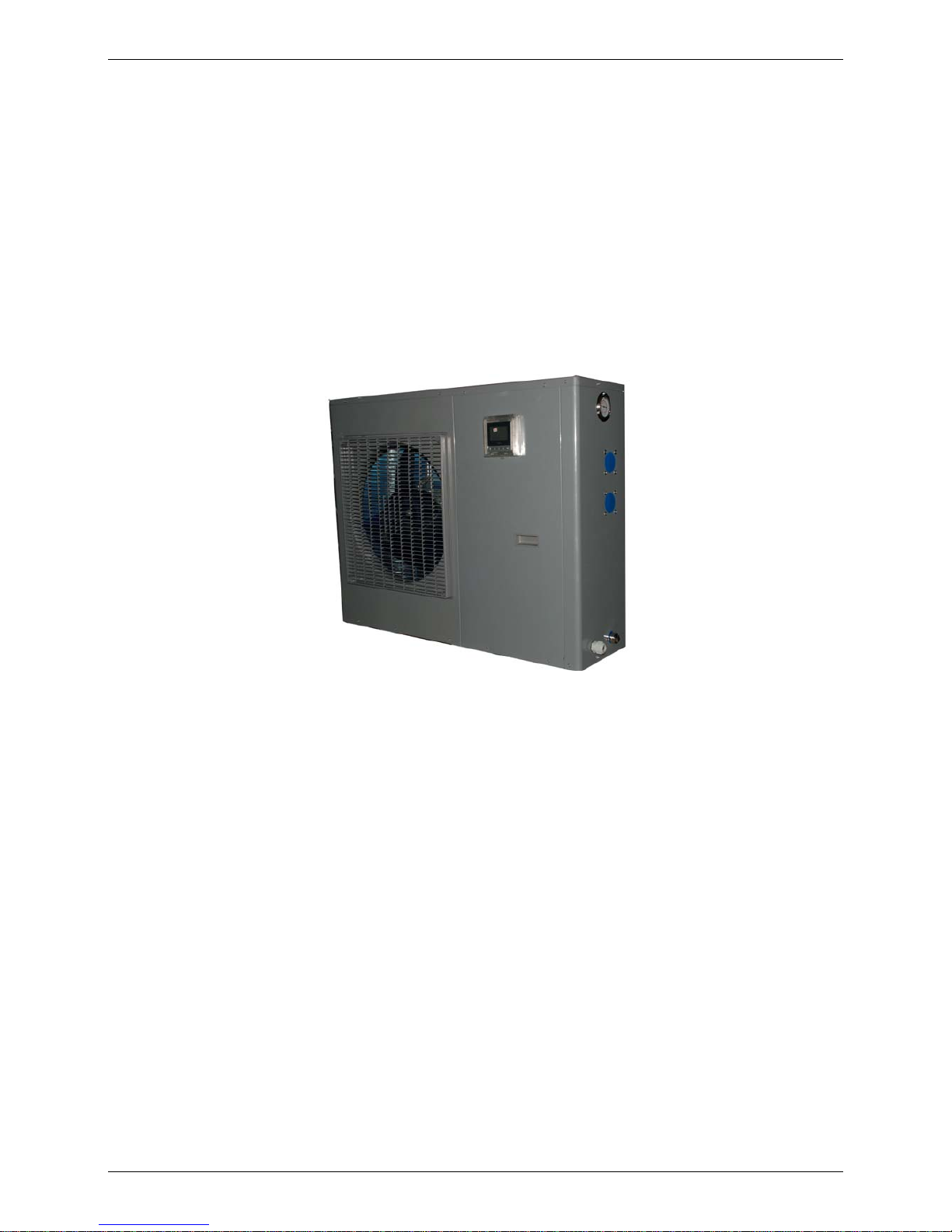
MDV Swimming Pool Type
Heat Pump Water Heater
Technical Manual
Applicable Models:
LRSJ-60/NYN1
LRSJ-80/NYN1
LRSJ-120/NYN1
LRSJ-140/NYN1
Midea reserves the right to discontinue, or change at any time, specifications or designs without notices and
without incurring obligations.
Page 2

2
Contents
Part 1 General Information ........................................................................3
1. Measurements....................................................................................................... 4
2. External Appearance............................................................................................ 4
3. Nomenclature........................................................................................................ 5
4. Features................................................................................................................. 6
Part 2 Outdoor Units...................................................................................7
1. Specifications....................................................................................................... 8
2. Capacity&COP table........................................................................................... 17
3. Dimensions ......................................................................................................... 17
4. Service Space ..................................................................................................... 18
5. Wiring Diagrams................................................................................................. 19
6. System refrigerant Diagrams............................................................................. 17
7. Exploded View .................................................................................................... 22
8. PCB explain......................................................................................................... 22
Part 3 Installation......................................................................................26
1. Precautions......................................................................................................... 27
2. Installation information...................................................................................... 28
3. Unit Appearance and Composition................................................................... 29
4. Accessories......................................................................................................... 30
5. Inspecting and Handling the Unit ...................................................................... 30
6. Electric Wiring..................................................................................................... 31
Part 4 Trial Operation ...............................................................................33
1. Confirmation before the trial operation............................................................ 34
2. OPERATING INSTRUCTION............................................................................... 34
3. PCB explanation.....................................................................
4. Maintenance............................................................................
5. Malfunctions and Resolutions...............................................
Page 3

3
Part 1
General Information
1. Measurements...................................................................4
2. External Appearance........................................................4
3. Nomenclature....................................................................5
4. Features.............................................................................6
Page 4
4
1. Measurements
Model
Dimension
(mm:
W*H*D)
Net weight / Gross weight
(kg)
Power Supply
CE-LRSJ-60/NYN1
1015*705*385 64/73 220~240V-1ph-50Hz
CE-LRSJ-80/NYN1
1015*705*385 66/77
220~240V-1ph-50Hz
CE-LRSJ-120/NYN1
1050*855*315 75/85
220~240V-1ph-50Hz
CE-LRSJ-140/NYN1
1050*855*315 75/85
220~240V-1ph-50Hz
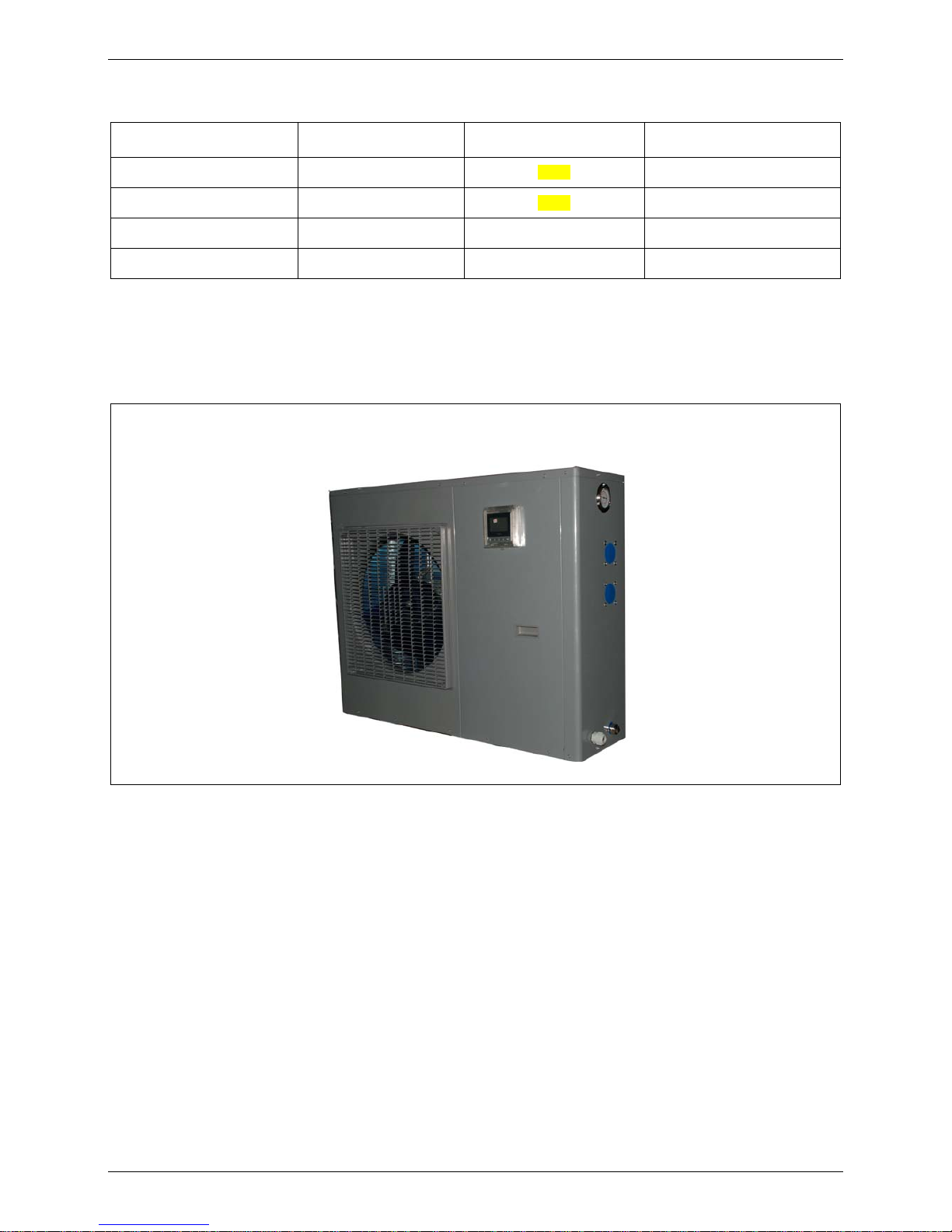
2. External Appearance
LRSJ-60/NYN1 LRSJ-80/NYN1 LRSJ-120/NYN1 LRSJ-140/NYN1
Page 5

5
3. Nomenclature
Household Water Heating Unit
23
45
6
7
8
Power supply specification code
-
Heating mode code
Rated hot water output, unit: 100 W
whether the system with pump
Installation type code
cooling recovery code
Export model code
/
-
9
Other functions code
10 11
12
-
Water supply pump lift code
Refrigerant code
Design code
1
Export model code
For example:
-
/
Water heat ing unit code
Rated hot water output, unit: 100 W
RSJ
L
Wi th cooling function
60
N
Y
N1
No water pump with machine
Heating mode code:swimming pool
Refrigerant type :R410a
Page 6
6
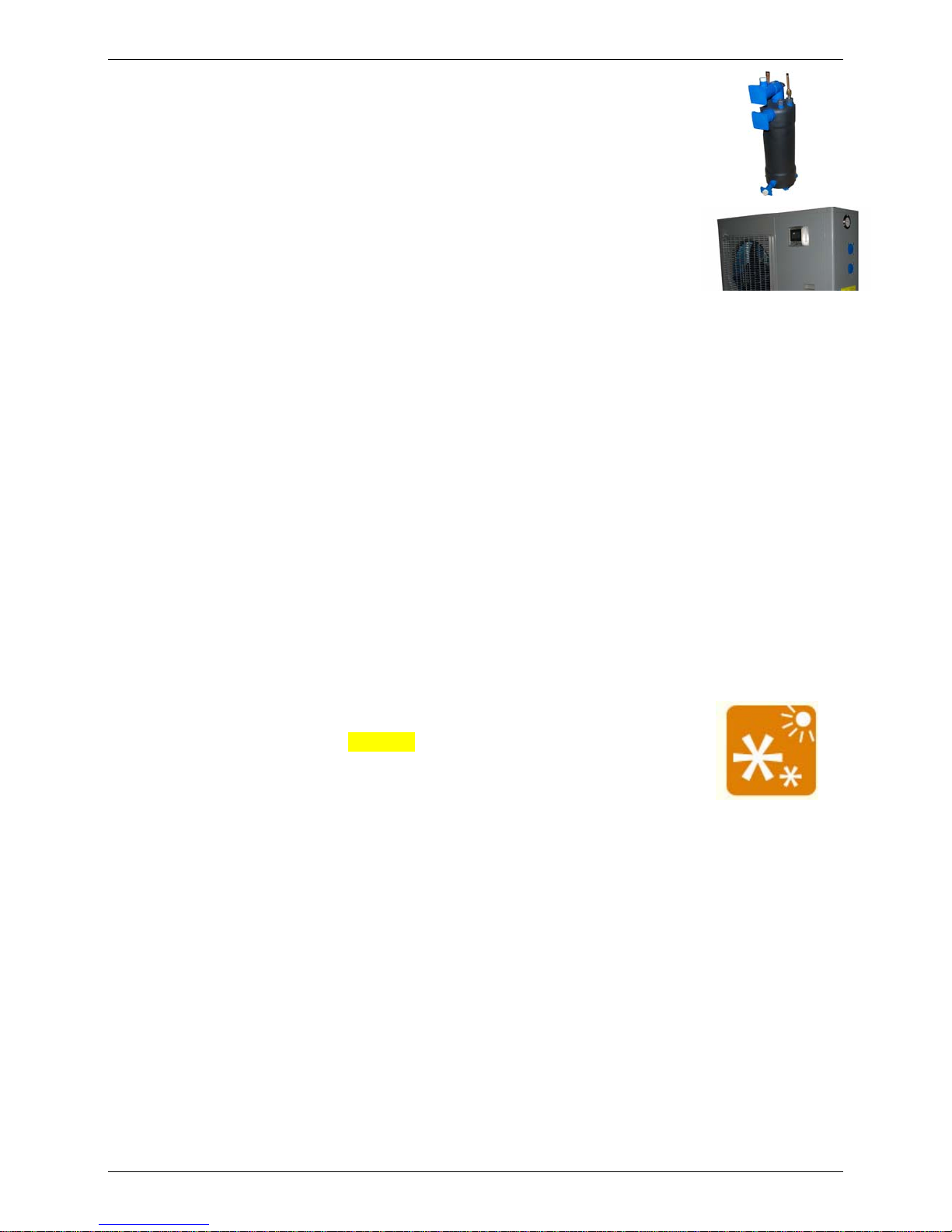
4. Features
4.1 Titanium heat exchanger
a. Excellent prevent eroding material,keep the machine long life.
b. High energy efficiency.
4.2 LCD display and build in high pressure meter in refrigerant side
User can see the machine running parameter and the state quickly.
Engineer can see the machine discharge pressure quickly, get hold of the machine
running reliablity .
4.3 About the 3-minute protection
Restart or open the manual switch after the unit has shut,down. Unit will not start immediately until 3
minutes later,because of the self-protect function of the compressor.
4.4 Dsfrosting function
In case of the unit requiring deicing during heating operation,TO prevent the heating efficiency from decreasing,
defrosting operation will turn on automatically (approx. 2~8 minutes) .
In the process of defrosting operation, the unit air supply motor will stop running.
4.5 Safety
a. Realize isolation between water and electricity. No electric shock problem, more safety.
b. No fuel tubes and storage, no potential danger from oil leakage, fire, explosion etc.
4.6 Autmatic Control:
Automatic start-up and shutdown, automatic defrosting by revising refrigerant cycle. Save you much extra
operation.
4.7 R410a gas, Environmental protection.
a. No discharge of poisonous gas.
b. No pollution to atmosphere and environment
4.8 All-the-weather Running.
Within the temperature range from -7 to 38℃, it will not be affected by night, cloudy sky,
rain even snow whether.
Page 7

7
Part 2
Outdoor Units
1. Specifications....................................................................8
2. Capacity & COP table .....................................................17
3. Dimensions......................................................................17
4. Service Space..................................................................18
5. Wiring Diagrams .............................................................19
6. System refrigerant Diagrams.........................................22
7. Exploded View.................................................................22
8. PCB explain.....................................................................22
Page 8
8
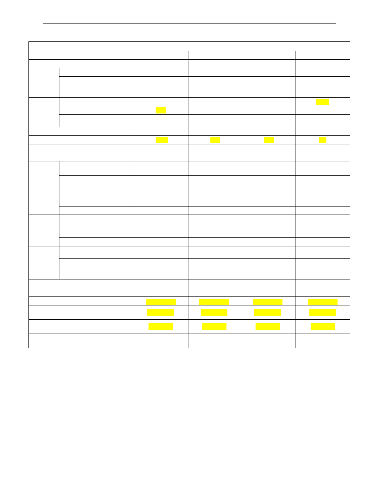
1. Specifications
HPWH SPECIFICATION
Model CE-LRSJ-60/NYN1 CE-LRSJ-80/NYN1 CE-LRSJ-120/NYN1 CE-LRSJ-140/NYN1
Power supply Ph-V-hz 220-240V 50Hz 1Ph 220-240V50Hz1Ph 220-240V 50Hz 1Ph 220-240V 50Hz 1Ph
Capacity
kW 6 8 12 14
Input
kW 1.15 1.52 2.40 2.55
Water
Heating
Outdoor ambient
temperature
(-7℃~38℃) (-7℃~38℃) (-7℃~38℃) (-7℃~38℃)
Capacity kW 4.0 5.8 8.4 10.35
Input kW 1.25 1.5 2.4 2.9
Water
Cooling
Outdoor ambient
temperature
(15℃~43℃) (15℃~43℃) (15℃~43℃) (15℃~43℃)
COP 5.2 5.3 4.9 5.3
Max power kW 1.45 1.9 3.3 3.5
Outdoor noise level
dB(A) 58 58 58 58
Refrigerant type/Quantity
Kg R410A/1.0 R410A/1.25 R410A/1.6 R410A/1.85
Heat exchanger
material
Titanium-tube
thermal exchanger
Titanium-tube
thermal exchanger
Titanium-tube
thermal exchanger
Titanium-tube
thermal exchanger
Water inlet and
outlet pipe
diameter
mm
DN50 DN50 DN50 DN50
Drain pipe
diameter
mm
DN25 DN25 DN25 DN25
Heat
exchanger
Max. pressure
MPa 0.4 0.4 0.4 0.4
Fin type
Hydrophilic
aluminium
Hydrophilic
aluminium
Hydrophilic
aluminium
Hydrophilic
aluminium
Tube outer type
innergroove tube innergroove tube innergroove tube innergroove tube
Air side
exchanger
Air outflow mode
air flow from rear air flow from rear air flow from rear air flow from rear
Dimension
(W*H*D)
mm
1015*705*385 1015*705*385 1050*855*315 1050*855*315
Packing
(W*H*D) mm 1095*755*455 1095*755*455 1170*905*410 1170*905*410
Outdoor
unit
Net/Gross weight
kg 64/73 66/77 75/85 75/85
Water contented capacity (m3)
40.0 50.0
60~85 75~100
Hot Water Yield
m
3
/h
2.3 2.8 3.8 3.8
Wire controller
KJRH-90B/E KJRH-90B/E KJRH-90B/E KJRH-90B/E
Water Heating Outwater Temp
℃
11℃~35℃ 11℃~35℃ 11℃~35℃ 11℃~35℃
Water Cooling Outwater Temp
℃
6℃~30℃ 6℃~30℃ 6℃~30℃ 6℃~30℃
Compressor current protection
value A
10 12 20 22
Remark:
1. The test conditions: outdoor temp.
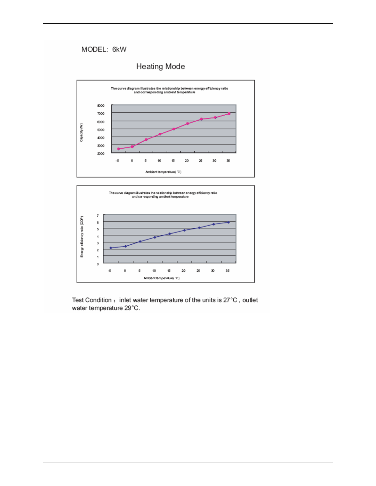
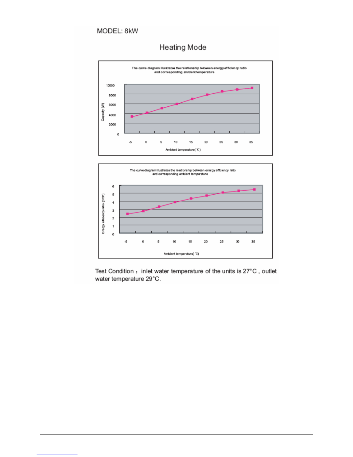
Water Heating: outdoor temp. 24/19℃(DB/WB), inlet water temp. 27℃,outlet water temp. 29℃
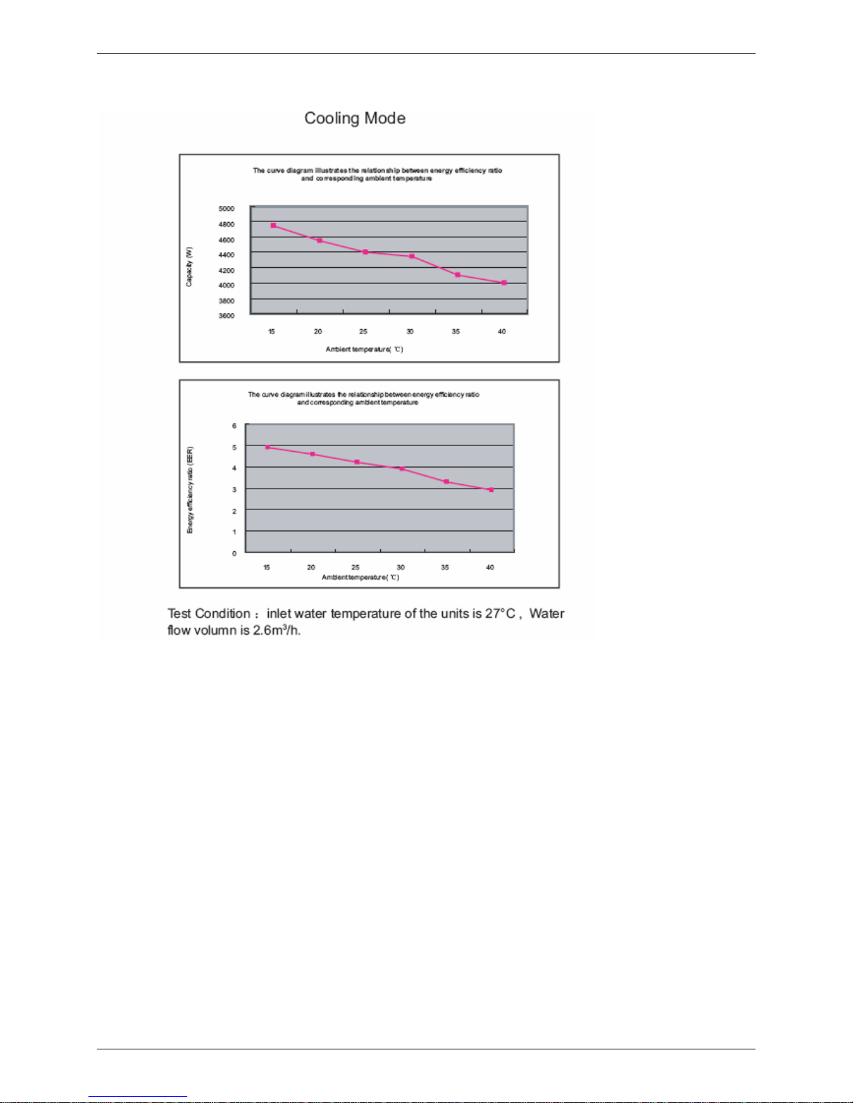
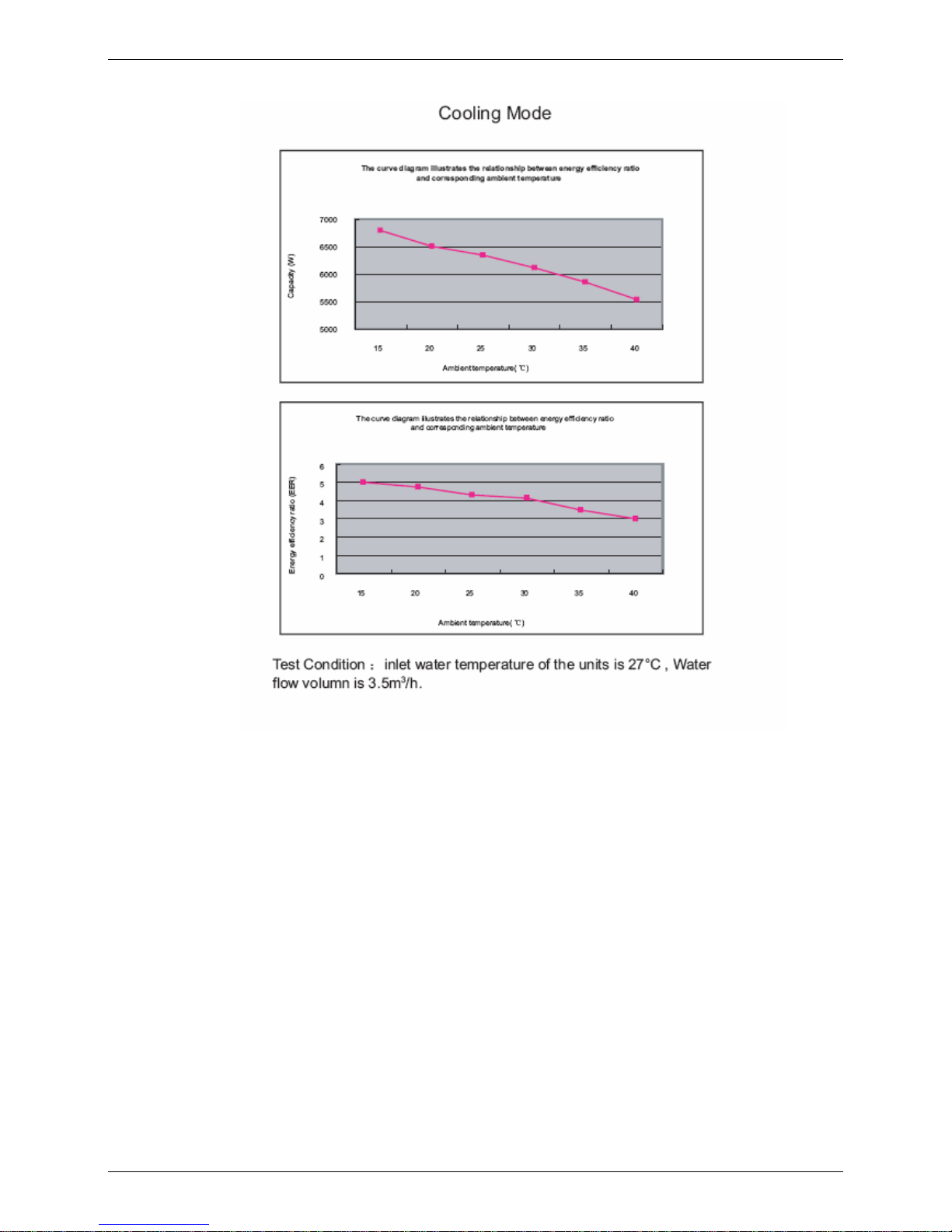
Water Cooling: outdoor temp. 35/24℃(DB/WB), inlet water temp. 27℃
2. The specification may be changed for product improvement, please refer to the nameplate.
Page 9
9
2. Capacity & COP curve
Page 10
10
MODEL : 6 kw
Page 11
11
Page 12
12
MODEL :8 kw
Page 13

13
Page 14

MODEL :12 kw
14
Page 15

15
Page 16

16
Page 17

17
3.
Dimensions
855 705 H
315 385 E
1050 1015 D
165 170 C
333 390 B
590 610 A
12KW
14KW
6KW
8KW
MODEL
Page 18

18
4. Service Space
Page 19

19
5. Wiring Diagrams
6Kw and 8Kw wiring diagrams:
Page 20

20
12Kw and 14Kw wiring diagrams:
Page 21

21
6. System Rfrigerant Diagrams
comp.
evaporator
titanium heat
exchanger
four-way
valve
water
pump
T3
T4
T6
Tp
T
out
high pressure
protection valve
Page 22

22
7. Exploded View
MODEL: LRSJ-120/NYN1 & LRSJ-140/NYN1
、
Page 23

23
No. Part Name Quantity No. Part Name Quantity
1
Rear net
1 12.9
Wire joint
1
2
Side board
1 12.10
Wire clamp
2
3
Target switch
1 12.11
Wire joint
2
4
Main capillary ass'y
1 13
Handle
2
5
Titanium heat exchanger
1 14
Wire controller
1
6
Hight pressure meter
1 15
Front side board
1
7
right side board
1 16
Front panel
1
8
Base ass'y
1 17
Grille
1
9
Solenoid
1 18
Axial flow fan
1
10
4-way valve ass'y
1 19
Motor
1
10.1
Pressure controller
1 20
Condenser ass'y
1
10.2
4-way valve
1 20.1
Flute shape pipe ass'y
1
10.3
Accumulator tank
1 21
Left bracket
1
11
Compressor
1 22
Rear supporter
1
12
E-part box ass'y
1 23
Motor bracket ass'y
1
12.1
Main controller board ass'y
1 24
Cover
1
12.2
Middle connection board ass'y
1 25
Partition board ass'y
1
12.3
Relay
1 26
Temperature sensor
2
12.4
Motor capacitor
1 27
Temp.sensor ass'y
1
12.5
Transformer
1 28
Discharge temp sensor ass'y
1
12.6
Compressor capacitor
1 29
room temp sensor ass'y
1
12.7
Contactor
1 30
Compressor electric heater
1
12.8
Wire joint
1
Page 24

24
8. PCB explain
A
Page 25

25
■ A : appliance type dial code
CE-LRSJ-60/NYN1
self-checking
adress :0
CE-LRSJ-80/NYN1
self-checking
adress :1
CE-LRSJ-120/NYN1
self-checking
adress :2
CE-LRSJ-140/NYN1
self-checking
adress :3
Page 26

26
Part 3
Installation
1. Precautions ...................................................................277
2. Installation information................................................288
3. Unit Appearance .............................................................29
4. Accessories.....................................................................30
5. Inspecting and Handling the Unit..................................30
6. Water pipline diagrame ..................................................30
7. Water pump selection.....................................................31
8. Tools required for installation .......................................31
9. Electric connection.........................................................31
Page 27

27
1. Precautions
To prevent injury to the user or other people and property damage, the following instructions must be
followed. Incorrect operation due to ignoring of instructions may cause harm or damage.
The safety precautions listed here are divided into two categories. In either case, important safety
instructions are listed to which close attention must be paid.
WARNING
Failure to observe a warning may result in death.
CAUTION
Failure to observe a caution may result in injury or damage to the equipment.
WARNING
■ The water heating unit must be earthed effectively.
■ A creepage breaker must be installed near the power supply.
■ Ask your supplier for installation of the air source heat pump water heating units. Incomplete installation
performed by yourself may result in water leakage, electric shock, or fire.
■ Ask your supplier for the repair and maintenance. Incomplete repair and maintenance may result in
water leakage, electric shock or fire.
■ In order to avoid electric shock, fire or injury, if any abnormality is detected, such as smell of fire, turn off
the power supply and call your supplier for instructions.
■ Never replace a fuse with that of wrong rated current or other wires when a fuse blows out. Use of
wrong wire or copper wire may cause the unit to break down or a fire.
■ Do not insert fingers, rods or other objects into the air inlet or outlet. When the fan is rotating at high
speed, it will cause injury.
■ Never use a flammable spray such as hair spray, lacquer paint near the unit. It may cause a fire.
■ Never touch the air outlet or the horizontal blades while the swing flap is in operation. Fingers may
become caught or the unit may break down.
■ Never put any objects into the air inlet or outlet. Objects touching the fan of high speed can be
dangerous.
■ Do not dispose this product as unsorted municipal waste. Collection of such waste separately for
special treatment is necessary.
■ The appliance shall be installed in accordance with national wiring regulations.
CAUTION
■ Do not use the air-source water heater for other purposes.
■ Before cleaning, be sure to stop the operation and turn the breaker off or pull out the power cord.
Otherwise, an electric shock and injury may be caused.
■ In order to avoid injury, do not remove the fan guard on the outdoor unit.
■ Do not operate the air-source water heater with a wet hand. An electric shock may be caused.
■ In the place and the wall where water may be spattered, the installation height must be more than 1.8m.
■ At the water inlet, the One Way valve must be installed.
■ It’s normal if some water drips from the hole of PT valve in operation. But, if the water is in a great
amount, call your supplier for instructions.
■ After a long use, check the unit stand and fittings. If damaged, the unit may fall and result in injury.
■ Arrange the drain hose to ensure smooth drainpipe. Incomplete drainpipe may cause wetting of the
building, furniture etc.
■ Never touch the internal parts of the controller.
Page 28

28
■ Do not remove the front panel. Some parts inside are dangerous to touch, and a machine malfunction
may be caused.
■ Never expose babies, plants or animals directly to the air flow. Adverse influence to babies, animals and
plants may be resulted.
2. Installation information
■ Enough space is installation and maintenance shall be preserved.
■ The air inlet and outlet should be free from obstacles and strong wind.
■ The bearing surface should be flat, able to bear weight of the unit and suitable for installing the unit
horizontally without increasing noise or vibration.
■ The operation noise and air flow expelled shall not affect neighbors.
■ No flammable gas is leaked nearby.
■ It is convenient for piping and wiring.
■ The maximum pressure is 0.4 Mpa, when the pressure more than 0.4 Mpa, Please add a pressure relief
valve.
CAUTION
■ Installing the equipment in any of the following places may lead to malfunction of the equipment (if it is
inevitable, consult the supplier):
1) The site contains mineral oils such as cutting lubricant.
2) Seaside where the air contains much salt.
3) Hot spring area where corrosive gases exist, e.g., sulfide gas.
4) Factories where the power voltage fluctuates seriously.
5) Inside a car or cabin.
6) Place like kitchen where oil permeates.
7) Place where strong electromagnetic waves exist.
8) Place where flammable gases or materials exist.
9) Place where acid or alkali gases evaporate.
10) Other special environments.
■ Precautions before installation
1) Decide the correct way of conveying the equipment.
2) Try to transport this equipment with the original package.
3) If the unit has to be installed on a metal part of the building, electric insulation must be installed, and the
installation must meet the relevant technical standards for electric devices.
■ Installation space
Before installing the unit, reserve the space of maintenance .
WARNING
■ Ask your supplier to install the air source heat pump water heating units. Incomplete installation
performed by yourself may result in a water leakage, electric shock, or fire.
■ The place without direct sunlight and other heat supplies. If there’s no way to avoid these, please install
a covering.
■ The unit must be securely fixed, or else, noise and shaking will be resulted.
■ Make sure that there’s no remora around the unit.
■ In the place where there is strong wind like seashore, fix the unit in the location protected from the wind.
Page 29

29
■ Carry the unit onto the site
1) In order to avoid scratch or deformation of the unit surface, apply guard boards to the contacting
surface.
2) No contact of fingers and other things with the vanes.
3) Don’t incline the unit more than 45° in moving, and keep it vertical when installing.
■ Install the unit.
1) The circulating air for every unit should be more than 2400m3/h.
2) Make sure there is enough Installation space.e
3) Outline dimensional drawing
Water treatment
In order to use our appliances under the best conditions, the following parameters must be respected:
free chlorine:max. 2.5mg/l, total bromine: max. 5.5 mg/l, PH between 6.9 and 8.0. If chemical or
electrophysical disinfection systems are used, the installer and user must contact the supplier to ensure they
are compatible with our materials. These systems must be installed after the heating system.
3. Unit Appearance
Page 30

30
4. Accessories
Check whether the following assemblies are complete.
Name Quantity Note Purpose
Installation& Operation Manual 1 —— Installation and Operation instruction
Seal ring 1 —— Discharge condensate water
Water outlet jointing pipe 1 —— Discharge condensate water
5. Inspecting and Handling the Unit
After delivery, the package should be checked and any damage should be reported immediately to the
carrier claims agent.
When handling the unit, take into account the following:
1.
Fragile, handle the unit with care.
Keep the unit upright in order to avoid compressor damage.
2. Choose before hand the path along which the unit is to be brought in.
3. Move this unit with original package.
4. When lifting the unit , always use protectors to prevent belt damage and pay attention to the balance of
the unit’s gravity.
6. Water pipeline diagram
8.1 Connection is established with a by-pass on the pool filtration circuit after the filter and before the water
treatment device (see diagrams upper). In order to connnect other heat source
8.2 During installation of connective pipe, you must beware not to let any dust or other foreign substance
intrude into pipe system.
8.3 Water inlet and outlet pipes can be installed as long as the water-heating A/C have been fixed.
8.4 Thermal insulation materials should be employed to seal up water outlet and inlet pipes.
8.5 Before operation, please confirm that the specifications of connective pipes are correct, and thermal
nsulation layer have been wrapped on pipes. It requires that all pipes have been sealed up, and no water
leakage has been detected.
Page 31

31
8.6 Hydraulic circuit test pressure: 3 bars - Hydraulic circuit operating pressure: 1.5 bar
pressure drop 2.2 mCE (0.22 bar)
7. Water pump selection
Model Water flow
Recommendatory flow
LRSJ-60/NYN1 0.8~20m3/h
3m3/h
LRSJ-80/NYN1 0.8~20m3/h
4m3/h
LRSJ-120/NYN1 1.5~20m3/h
5m3/h
LRSJ-140/NYN1 1.5~20m3/h
5.8m3/h
8. Tools required for installation
- 1 set of flat head screwdrivers
- 1 set of crosshead screwdrivers
- 1 cutter
- 1 wire stripper
- 1 pipe or round head spanner 13
- 1 ratchet spanner
- 1 pliers
- 2 straps (for handling)
9. Electic connection
9.1 Power specification
Diameter of the thinnest cable (mm2)
(Metal pipe and synthetic resin pipe wiring)
Manual Switch
(A)
Item
Model
Power Supply
Size (continious length
<30 m
Earthling Wire Capacity Fuse
LRSJ-60/NYN1 220~240V-1ph-50Hz 2.5 2.5 ≥30 20
LRSJ-80/NYN1 220~240V-1ph-50Hz 2.5 2.5 ≥30 20
LRSJ-120/NYN1 220~240V-1ph-50Hz 4.0 4.0 ≥30 25
LRSJ-140/NYN1 220~240V-1ph-50Hz 4.0 4.0 ≥30 25
9.2 Power Supply Wiring .
A. Power Supply Schematic Diagram
Earthing
Water Heating Unit
Manual Switch
Power
supply
Creepage Breaker
Warming:
Although there is a leakage protector in the electric control box of the unit, for the security reason, it is
required that a leakage protection equipped cable and Earthing should be applied for the unit according to
the requirement on the above diagram.
B. Cable Diameter Selection
The power supply wiring refers to the wiring to the main line (a) of junction box and the wiring (b) to the
power supply equipment. Please select the cable diameter according to the following methods
Page 32

32
1) Diameter of the main line (a):
Get from the power supply specification table according to the sum of horsepower of the unit.
2) Diameter of the wiring from the junction box to the power supply equipment:
When the water heaters are less than 5 sets, the diameter the wiring from the junction box to the power
supply equipment should be the same as the main line (a); when the water heaters are more than 6 sets, the
power supply equipment should have two sets of electric control box and the diameter should be get from
the power supply specification table according to the sum of horsepower of the units connected by the
electric control box.
9.3 Electric wiring diagram
Electric wiring diagram for Model 6kW 8kW 12kW 14kW
Page 33

33
Part 4
Trial Operation
1. Confirmation Before the Trial Operation......................34
2. Operating Instruction .....................................................34
3. Fault code list.....................................
4. Self-checking......................................
Page 34

34
1. Confirmation Before the Trial Operation
1.1 All the installation is complete.
1.2 Water heater is installed correctly.
1.3 The pipelines and wiring are correct.
1.4 The accessories are installed correctly.
1.5 The drainage is smooth.
1.6 The thermal insulation is sound.
1.7 The earthing wire is connected correctly.
1.8 The power voltage is consistent with the rated voltage of the heater.
1.9 No obstacle at the air inlet and outlet of the unit.
1.10 The leakage protector can work effectively.
2. Operating Instruction
2.1 The appearance of controller
2.2 Name and function description of LCD screen of wire controller
Page 35

35
2.3 Names of keys on the wire controller and the keypad operation description
2.4 Application of wire controller
Preparation before running the unit.
When you run the unit for the first time, all the indicators on the wire controller will light for 3s, and then,
display the fiducial web page. After no operation for 40s, all indicators will go out automatically except POOL
TEMP indicator lighting. When the unit is running, if there is no operation or malfunction for 10s, the
backlight of the display will go out automatically.After 30s ,all indicator will disappear except operation mode
and pool temp.
By default, the unit operates Heat Mode. Change:
Mode Selection
The unit is enhanced with three operation modes, Cool Mode, Heat Mode and Pump Mode.
Cool Mode: The unit cools down swiming pool water by compressor drive according to heat-pump principle.
Used when the swiming temp. is high in summer.
Heat Mode:The unit heats swiming pool water by compressor drive according to heat-pump principle. Used
when the ambient temp. is low.
Pump Mode:The pump run for circling the water. Used when trial run or other necessary situation.
By default, the unit operates Heat Mode. Change:
Page 36

36
Temperature set
Temp. displayed is the setting
water temp. Default is 28℃ and the Cool mode setting range is
10~30℃the heat mode setting range is 20~35℃
Power on/Power off
Press Power On/Power Off button after all the above have finished
and the system will run as the setting. And simply press the same
button to stop it.
Operation status display
Page 37

37
3. Fault code list
4. Self-checking function
1. Nomal display : T6 ;
2. Mode code :(0 6KW; 1 8KW; 2 12KW; 3 14KW);
3. Operate mode:(1 cooling;16 water heating;4 pump );
4. Fan speed(0 stop;1 low ;2 hight);
5. T4;
6. Tp;
7. T3;
8. T6;
9. Tout;
10. Comperssor current ;
11. Ts;
12. The last error code“--”
 Loading...