

Page 1
Service Manual
Drum Washing Machine
Http://global.midea.com.cn
Note:
Before serving the unit,please read this at first,
Always contact wih your service center if meet problem.
Glory(6.0/7.0/8.0KG)
Page 2

1.
…...................................................................................................................
2. INTRODUCTION
2.1 Characteristics of product
..................................................................................................................
2.2
.............................................................................................................................
SAFETY PRECAUTION
OF WASHING MACHINE
Working principle
04
06
06
P.02
TABLE OF CONTENTS
3.
TROUBLESHOOTING
.4 3
Fault tree
3.4.1 non-heating malfunctionMaintenance
...........................................................................................
12
3.4.2 Door non-locked & its maintenance
..............................................................................................
13
3.4.3 No water inlet or water inlet overtime
............................................................................................
14
3.4.4. Heating beyond the setting temperature its maintenance
.......................................…....................
15
3.4.5. of non-drain or drain exceed the setting timeMaintenance
............................................................
16
3.4.6. Water inlet overflow malfunction maintenance
............................................................................
17
3.4.7. Drum non-rotating malfunction maintenance
...............................................................................
18
3.4.8. water inlet and water outlet at the same time Maintenance
...........................................................
19
..........................................................................................................
4.1.1Undo the back cover
.........................................................................................................................
4.1.2 Undo the top cover
.........................................................................................................................
4.1.3 Undo the control panel
.....................................................................................................................
4.1.4 Undo the lower panel
...................................................................................................................
4.1.5 Undo the door lock
..........................................................................................................….........
4.1.6 Undo the front panel
....................................................................................................................
4. UNPACKING WAYS OF MAIN PARTS
4.1 Overeview the unpacking step
........................…........................................................................................
07
3.1 Malfuction and solution
4.1.11 Undo the inlet valve
....................................................................................................................
4.1.12 Undo the pressure switch
............................................................................................................
4.1.13 Undo the pulley
...........................................................................................................................
4.1.14 Undo the upper counterweight
...................................................................................................
4.1.15 Undo the absorber pin
................................................................................................................
4.1.16 Undo the filter
.............................................................................................................................
4.1.7 Undo the faced conterweight
........................................................................................................
4.1.8 Undo the gasket
............................................................................................................................
4.1.9 Undo the PCB panel
.....................................................................................................................
4.1.10 Undo the detergent box
...............................................................................................................
4.1.18 Undo the heater
...........................................................................................................................
4.1.19 Undo the NTC temperature sensor
..............................................................................................
4.1.20 Undo the door glass
.....................................................................................................................
4.1.21 Undo the panel support
...............................................................................................................
4.1.22 Undo the drum tub assembly
......................................................................................................
4.1.24 Undo the motor
21
21
21
22
22
22
20
24
24
25
25
26
26
23
23
24
27
27
28
28
28
...........................................................................................................................
29
26
4.1.17 Undo the drain pump
.................................................................................................................
3.2 Sevice mode
.......................…....…..............................................................................................
09
26
4.1.23 Undo the absorber
.......................................................................................................................
29
3.3 Schedule of failure alarm
.......................…....…...............................................................................
11
Page 3

P.03
TABLE OF CONTENTS
5. CIRCUIT DIAGRAM
6. EXPLORED VIEW & LIST OF PARTS
5.1 The failure diagnosing and changing components
6.1.5 Door_assembly
6.1.4 Dispenser_assembly
6.1.3 Top cover_sub
6.1.1 Cabinet_sub
6.1.2 Tub_sub
29
34
35
36
37
38
..........................................................................
...............................................................................................................................
..............................................................................................................................
........................................................................................…...............................
.................................................................................................................
.........................................................................................................................
6.1 Explored view & of PartsList
34
...................................................................................................
5.2 The circuit program & wiring connection figure .............................................................................. 30
5.3 The electric critical part .....................................................................................................................
31
Page 4

1.SAFETY PRECAUTION
P.04
- If the supply cord is damaged,it must be replaced by the manufacturer,its service agent or similar
-ly qualified in order to avoid a hazard.
- The new hose-sets supplied with the appliance are to be used and that old hose-sets should not be
reused.
- This washing machine is for indoor use only.
- The openings must not be obstructed by a carpet.
- (This warning is only for EUROPEAN market )This appliance can be used by children aged from
8 years and and persons with reduced physical,sensory or mental capabilities or lack of experience
and knowledge if they have been given supervision or instruction concerning use of the appliance
in a safeway and understand the hazards involved. Children shall not play with the appliance.
Cleaning and user maintenance shall not made by children without supervision.
- (This warning is not for EUROPEAN market)This appliance is not intended for use by persons
(including children) with reduced physical, sensory or mental capabilities, or lack of experience
and knowledge, unless they have been given supervision or instruction concerning use of the
appliance by a person responsible for their safety.Children should be supervised to ensure that
they do not play with the appliance.
- Pull out its plug from the power socket before cleaning or maintenance.
- Make sure that all pockets are emptied.
- Sharp and rigid items such as coin,brooch,nail,screw or stone etc.may cause serious damages to
machine.
- Pull out its plug and cut off water supply after the operation.
- Please check whether the water inside the drum has been drained before opening its door.Please
do not open the door if there is any water visible.
- Pets and kids may climb into the machine. Check the machine before every operation.
- Glass door may be very hot during the operation.Keep kids and pets far away from the machine
during the
operation.
- Take care that power voltage and frequency shall be identical to those of washing machine.
- Do not use any socket with rated current less than that of washing machine.Never pull out power
plug with wet hand.
- To ensure your safety,power cord plug must be inserted into an earthed three-pole socket.Check
carefully and make surethat your socket is properly and reliably earthed.
- Children of less than 3 years should be kept away unless continously supervised.
- Kids should be supervised to ensure that they do not play with the machine.
- Packing materials may be dangerous to the kids.
Please keep all packing materials (plastic bags,foams etc) far away from the kids.
- Washing machine shall not be installed in bath room or very wet rooms as well as in the rooms
with explosive or caustic gases.
- Make sure that the water and electrical devices must be connected by a qualified technician in
accordance with the manufacturer's instructions and local safety regulations.
- Before operating this machine,all packages and transport bolts must be removed.Otherwise,the
washing machine may be seriously damaged while washing the clothes.
- Before washing the clothes at first time, the washing machine shall be operated in one round of
the whole procedures without the clothes inside.
- Your washing machine is only for home use and is only designed for the textiles suitable for
machine washing.
- The washing machine with single inlet valve only can be connected to the cold water supply. The
washing machine with double inlet valves can be connected to the hot water and cold water supply.
Page 5

- Flammable and explosive or toxic solvents are forbidden.
Gasoline and alcohol etc.Shall not be used as detergents.
Please only select the detergents suitable for machine washing, especially for drum.
- It is forbidden to wash carpets.
- Be careful of burning when washing machine drains hot washing water.
- Never refill the water by hand during washing.
- After the program is completed, Please wait for two minutes to open the door.
- Please remember to disconnect water and power supply immediately after the clothes are washed.
- Do not climb up and sit on top cover of the machine.
- Do not lean against machine door.
- Please do not close the door with excessive forces.If it is found difficult to close the door,please
check if the excessive clothes are put in or distributed well.
- The household washing machine isn't intended to be built-in.
- Cautions during Handling Machine
1.Transport bolts shall be reinstalled to the machine by a specialized person.
2.The accumulated water shall be drained out of the machine.
3. Handle the machine carefully. Never hold each protruded part on the machine while lifting.
Machine door can not be used as the handle during the conveyance.
- Notes on disposal:
This marking indicates that this product should not be disposed with other household wastes
throughout the EU.To prevent possible harm to the environment or human health from
uncontrolled waste disposal,recycle it responsibly to promote the sustainable reuse of
material resources.To return your used device,please use the collection systems or contact
the retailer where the product was purchased. They return and can take this product for
environmental safe recycling.
2.SAFETY PRECAUTION
P.05
Page 6

2.INTRODUCTION OF PRODUCTS
P.06
It is the latest designed machine, which have many advantages such as fashion, large rated washing
and large washing range. Specifically, its feature is as following:capacity
1.Large washing range from cotton to wool and silk.
2.Gentle washing: no twist and little abrasion.
3.Electron auto-balance system, that is, the PCB panel controls the speed of spin and ensures uniform
distribution of clothes to reduce the wear of textile caused by its vibration.
4.The drum of this machine is made of stainless steel of high quality and the cabinet is durable.
5.The maximum temperature of washing water could be controlled independently and it is up to 90℃.
6.Unique washing methods: rain, soak, throwing-knocking knead and so on, which can wash clothes
uniformly and improve washing performance.
7.Safety guard: water level control, door lock etc.
8.Anti-crease function: there is an automatic anti-crease and soak function in the synthetic program,
that’s, it doesn't drain at the end of washing and leave the clean extile in the water of the drum to
achieve the function of less crease, especially delicate.
9.Function of adjusting speed : select different spin speed according to textile.
10.Electronic water distribution system: The machine uses PCB to control the inlet valve and distribute
water properly at the different stages and dissolve detergent and softener absolutely to improve
performance.washing
2.2.Working principle
Drum washing machine wash clothes mainly in virtue of mechanical friction, chemical force and
temperature force. When the machine works, the motor runs clockwise several seconds and runs
anti-clockwise several seconds to drive the drum whose three lifters hold up the clothes pressing
the inside of the drum. When clothes rise close to the against top, because the speed of motor is low
and the centrifugal force is not enough to overcome the gravity, clothes fall and impinge with washing
liquid (like manual throwing-knocking washing). The second force is the extrusion force of clothes
(like manual extrusion). The last force is the friction between clothes, clothes and lifters(like manual
knead). To improve washing performance, automatic drum washing machine could automatically heat
the washing liquid, whose temperature can be adjusted from 0℃ to 90℃.
The high temperature quickens the movement of the numerator of the washing liquid and speedups the
2.1 haracteristics of product
C
Chemical reaction. In a word, drum washing machine destroys bonding force between dirt and clothes
in virtue of intergraded force of water, detergent and mechanical force, to clean away the dust.
Page 7
3.TROUBLESHOOTING
SolutionDescription
The washing machine does not work
Close the washing machine's door.
Confirm and press the start key.
Water leakage Correctly connect the inlet water pipe.
The spin of the clothes is abnormal
Reload and distribute the laundry evenly in the drum.
Thereis the peculiar smell in th e
washing machine
Run a Self-clean cycle without any clothes.
No water is visible in the drum No fault-water is under the visible area.
There is the remaining water in th e
softener's box
No fault- the effect of the softener will not be affected.
The remaining detergent is left on
the clothes
The water-fast component of the non-phosphorus
detergent will be left on the clothes to form the line
scale. Plesae select or【 Spin 】programme or brush
away the fleck with the brush when the clothes is dried.
The washing machine does not fill
The washing machine fills and
empties at the same time.
Make sure the end of the drainage pipe to be higher
than the water level of the inside the machine .
Check if the drainage pipe and sewage have been
sealed, if they have been, there will be the poor
ventilation to cause the siphonage effect.
No drainage of the washing machine
Check if the drainage pumps is blocked.
Check if the drainage pipe is bent or blocked.
Check the height of the drainage nozzle, make sure it is
0.6-1 meter from the bottom of the washing machine.
Vibration of the washing machine
Level the washing machine.
Fasten the footing.
To check if the internal packing for the transportation
have all been removed.
Check the selection of .the procedure
Check the water
Put through the feed-water.
To check it the inlet water pipe is bent or blocked.
Close the washing machine's door.
Pressure to seeif the water pressure is insufficient.
Open the water tap.
The bubble spills from the detergent
box
Check if the detergent is excessive, if it is the
specialized detergent for the cylinder washing machine.
Reduce the usage amount of the detergent in the next
time's wash.
Dip one scoop of the softener mixed with 1/2 liter of
water to the detergent box II.
3.1 Malfuction and solution
P.07
Page 8
3.TROUBLESHOOTING
The machine stops when the
procedure has not been finished
Power failure or water cut.
The drainage pump has noise during
the operation when the water has
just been drained
To stop for some time during th e
wash procedure
service centre.
If you cannot solve the above abnormal situations, would you please contact the nearest
The washing machine adds water automatically.
Because there is too much bubble in the tube, the
washing machine is cleaning the bubble.
SolutionDescription
The inner barrel water of the washing machine has
been drained but there is still a small amount of
water in the drainage pump and pipe. The drainage
pump continuously operates and takes in the air, and
at this time there is the noise, which is normal
situation.
P.08
Page 9

3.TROUBLESHOOTING
P.09
Before entering into service mode, make sure no water remains in the inner drum, if not, select drain
only program to drain them out.
Turn on the machine and in 30s.
Press or to select test program. Press button to confirm your selection
and start the selected test. If you want to go back to test selection interface, press the button to
cancel previous selection.
3.2.1 Version switchover (t01)
1) Enter into service mode, LED displays “t01”
2) Press button, LED displays “0xx”.x means current version.
3) Press to confirm switchover.
4) Press or to change version.
5) Press button continuously for 3s to confirm your change.
6) Press button to close all output and exit this program. LED displays “t01”.
3.2.2 Error code checking (t02)
1) Enter into error code mode, LED displays “Err”. Press button and LED displays
EXX(x=1,2,3….)
2) Press to show the last code and press to show the next code. The latest 10 error codes
can be found in system, and same error code is recorded one time even if it occurs more than one time
3) If no error information found, LED shows E00.
4) Press and button at the same time continuously for 3s, after hearing the beep, all the
error codes records deleted, LED displays E00.
5) Press button to exit, LED display t02.
3.2.3 Version information checking (t03)
Version information checking is used to show the current version information stored in nonvolatile
memory applications.
1) Enter into service mode, LED displays “cod”.
3) Press button, LED displays version number.
4) Press to go back to version information checking status, LED display “t03”.
3.2.4 UI Checking (t04)
1) Press button to illuminate the whole LED display.
2) Press button, the whole LED display flashes.
3) Press to stop flash, LED display “t04”
take turns [K2] [K4] [K2] [K4] buttons
[K2] [K3] [K5]
[K5]
[K5]
[K4]
[K2] [K3]
[K4]
[K5]
[K5]
[K2] [K3]
[K2] [K3]
[K5]
[K5]
[K2]
[K5]
[K5]
[K5]
[K5]
2) Press , LED displays project number.
3.2 Sevice mode
Start/Pau se
K1 K2
K3
K4
K5
Page 10

3.TROUBLESHOOTING
P.10
3.2.6 Pressure switch checking (t06)
1) Enter into service mode, drain out the water, LED displays LL.
2) Press button to activate inlet valve. LED displays level frequency once water lever get
the main wash level.
3) Press
3.2.7 Water temperature sensor and heater checking (t07)
1) Press button to activate the main inlet valve and get the water lever to heating level then
turn on the heater and 5 min later turned off automatically.
2) After heater turned on, LED displays the current temperature. Detect the real temperature of inner
drum and check with the numbers on the display.
3) Press button to exit, LED displays “t07”
3.2.8 Inlet valve checking (t08)
Enter into service mode, drain out the water, LED displays “UU”
Press button, LED displays “u3”and switch on the main wash inlet valve for 10 min.
4) Press button, LED displays “u2” and
3.2.9 Rotating checking (t09)
1) Enter into service mode, LED displays “tUB”
2) Press button, inner drum rotates in 45r/m clockwise for 15s and stop for 10s then rotates
counterclockwise for 15s, over and over again.
3) Press button to turn off the motor and exit, LED displays “t09”.
3.2.10 Spin speed checking (t10)
1) Press to enter into service mode, LED displays “spn”.
2 he number on the display goes up in the same pace with the real speed
and when it reach 400rpm, you need to press button to get the machine to reach its target speed.
( if declared speed ≥1000rpm, target speed is 1000rpm and if declared speed <1000rpm,target speed is
its declared speed)
3) Press button to exit and LED displays “t10”.
3.2.5 Drain pump checking (t05)
1) Enter into service mode, LED displays “PPt”.
2) Press button to drain out all the remaining water. If all water drained out, LED displays
“EP”,and 6 minutes later ,if there is still water remains in it, LED displays “FP”.
3) Press button to exit, LED displays “t05”
1)
2)
3) Press button, LED displays “u1” and switch on prewash valve for 5s.
switch on the main wash inlet valve for 5s.
5) Press button to switch on main wash and prewash valve and get the water lever to setting
level, then drain out the water.
) Press button again, t
[K5]
[K5]
[K5]
[K2] button 4 times to start water inlet valve for water supply, after the water level reaching
the overflow line, drain out all the water.
[K5]
[K5]
[K5]
[K2]
[K2]
[K2]
[K5]
[K5]
[K5]
[K5]
[K2]
[K5]
3.2 Sevice mode
Page 11
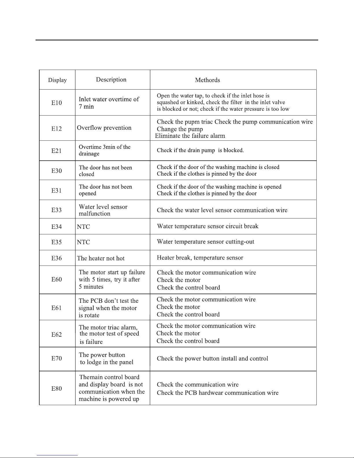
P.11
3.3 Schedule of failure alarm
3.TROUBLESHOOTING
Page 12
P.12
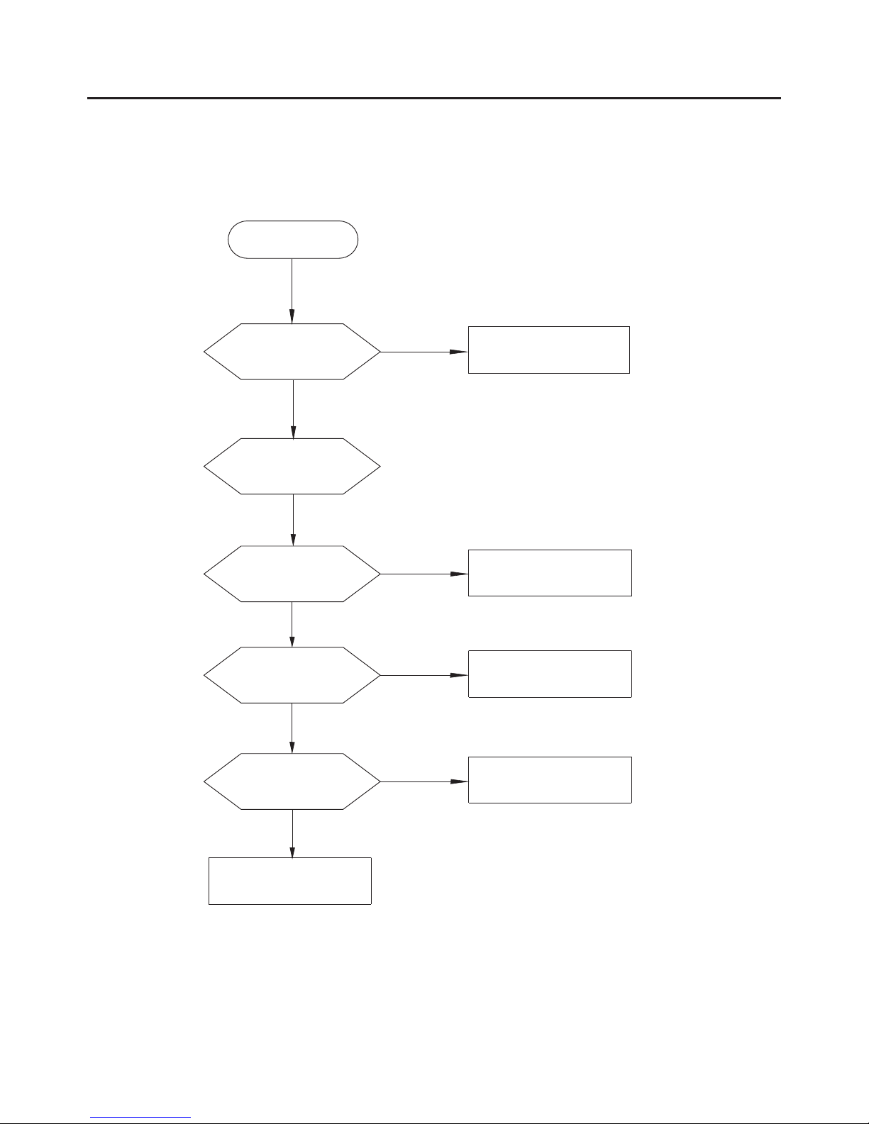
3.4 Fault tree
Reliable connection
Y
N
Whether the connect
is well
Change NTC
Y
N
Whether NTC is short
or open circuit
Y
Whether the pressure
switch is well or not
N
Y
Choosing new heating
temperature
Y
Whether to set up
non-heating
Non-heating
Whether the heater
is well
N
Change the heater
Y
Change the control panel
Maintenance non-heating malfunction1.
3.TROUBLESHOOTING
Page 13

P.13
2. Door non-locked & its maintenance
Close the door correctly
Whether the door is
closed correctly
Y
N
N
Push the start button
to start the program
N
Reliable connection
The door is
invalid and should
be replaced
lock
Y
Y
Y
Y
N
Door non-locked
Whether push the
start /pause button to
start theprogram
Change the control panel
Whether the voltage
between harness 1 and
harness 3 is about 220v
Whether the harness
connection between the
door lock and the main
board is well
3.TROUBLESHOOTING
Page 14

P.14
Change main board
Y
Whether the
connection is well
N
Door is invalid and
should be replaced
lock
Y
N
Y
Whether the door
is closed correctly
N
Y
Y
Whether the tap is opend
Y
No water inlet or
water inlet overtime
N
Y
N
Y
Y
N
N
N
Change the inlet valve
N
N
Change the control panel
Whether the
switch is well
pressure
Y
N
Y
Push start/pause button
Cleaning with brush
Change the
switch
pressure
3. No water inlet or water inlet overtime
Whether press
start/pause button
after choosing the
program
Whether door
lock 3 and 2 is
connected correctly
Whether the voltage
between door lock 1
and 3 is 220V
Whether the
electromagnetic
valve buzz
Whether the
connections of inlet
valve is well
Whether the inlet pipe
is fold or the water is
cut off
Whether the
inlet valve coil is
well
Whether the inlet filter
net is blocked
Whether the
connection of
pressure switch is
well
Connect
connections
3.TROUBLESHOOTING
Y
Page 15

P.15
4. Heating beyond the setting temperature its maintenance
Change NTC
Y
Whether the
connection is well
N
Whether NTC is
short circuit or
open circuit
Y
加热过度
Y
Change the control panel
Over heating
3.TROUBLESHOOTING
Page 16

P.16
N
Y
N
Whether the
door lock is
well
Close the door
Whether the
door is closed
Y
Y
Non-drain or
overtime drain
Change
panel
the control
N
Reliable connection
N
N
Y
Return to the normal station
Change the
drain pump
Y
Cleaning the
filter
N
Y
N
Y
Y
5. Maintenance of non-drain or drain exceed the setting time
Whether it is in
the state of pause
Push start/pause button
Whether the
pump is vibrating
Whether the
connection between
the pump and the main
board is loosened
Whether the
pump is blocked
or burned out
Whether the filter
is blocked
Whether the drain
pipe is fold or hung
too high
3.TROUBLESHOOTING
The means of detecting door
switch refers to the paragraph
of "no water inlet".
Page 17

P.17
6. Water inlet overflow malfunction maintenance
Hang the hose well
Whether the drain
hose is hung up
Y
N
Y
C
inlet valve
hange the inlet
Y
N
Reliable connection
Y
Y
N
Y
N
Water inlet overflow
Whether the electric
connection of pressure
switch is normal
Change the control panel
Whether the water
is in without power
Whether the gas pipe
or the connection is
leaking or deadlock
Change or revive
the gas pipe
Whether the
switch is well
pressure
3.TROUBLESHOOTING
Page 18

P.18
7. Drum non-rotating malfunction maintenance
Change the control panel
N
The drum is blocked
Drum non-rotating
Y
Whether the door
is closed correctly
Close the door
Whether the door
lock is well
Y
N
Change the door lock
N
Y
Y
Y
Whether the motor
is well
Whether the
connection of main
and auxiliary wiring
harness is well
N
Reliable connection
Y
Whether the inlet
is correct
N
Waiting inlet or inspect
overtime water inlet
malfunction
Whether the
switch is well
pressure
Y
Y
N
Replace it
N
Replace it
Detach strap,
whether the drum
is rotating flexibly
3.TROUBLESHOOTING
Page 19

P.19
8. Maintenance water inlet and water outlet at the same time
Whether the washer is
disposing the foam in
the drum
Change the control panel
N
Y
Normal phenomenon
Y
Water inlet and water outlet
at the same time
Whether the drain hose
is hung too low
N
Y
Hang the hose well
3.TROUBLESHOOTING
Page 20

P.20
4.UNPACKING WAYS OF MAIN PARTS
4.1 Overeview the unpacking step
1.
2. Undo top cover
3. Undo the control panel
4. Undo the lower panel
5. Undo the door lock
6. Undo the front plate
7.
8. Undo the gasket
9. Undo the PCB panel
10.Undo the detergent box
11.Undo the inlet valve
12.Undo the pressure
13.Undo the pulley
14.Undo the upper counterweight
15.Undo the absorber pin
16. Undo the filter
17.Undo the drain pump
18.Undo the heater
19.Undo the NTC
20.Undo the door glass
21.Undo the panel support
22.Undo the drum tub assembly
24.Undo the motor
Undo the back cover
Undo the facade counterweight
23.Undo the absorber
Page 21

P.21
4.UNPACKING WAYS OF MAIN PARTS
Operation step Picture
1 Undo the back cover
Undo two screws fit
between back plate and
cabinet, and then pull out
the back plate
2 Undo top cover
Undo 2 screws fit
between the top cover and
back cabinet
Push back the top cover
15mm until it leaves away
from, the control panel,
and then take it down.
3 Undo the control panel
Departing the top cover
(means as above)
Draw out the detergent
drawer
Loosen two screws fit
on the control panel
(facial).
Loosen two screws fit
on the control panel(top)
Press three clasps
between top control panel
and panel support.
Take out the control
panel inclined from the
cabinet
.
①
.
②
①
②
③
④
⑤
⑥
.
Page 22

P.22
Operation step Picture
4.UNPACKING WAYS OF MAIN PARTS
4 the lower panel
Loosen the screws fit on
the lower panel.
Pinch the clasp, and push
Undo
①
②
5 Undo the door lock
open the door of washing
machine.
Take the outer gasket
clamp to the drum.
①
②
Push door lock outward
direction.
Take out the door lock
and draw out the plug; pay
attention to of the position
the plug so as connectnot to
a wrong circuit next time.
③
④
6 Undo the front plate
Undo the door lock
(methods as followed).
Remove the lower
cover(methods as
followed).
①
②
Use coin or screwdriver
③
to open the filter cover.
③
④
Undo the screws in the
front plate.
Put the front plate up to
the plate clasp of the front
away from loading holder, the
and then take off the front plate.
it out.
Page 23

P.23
4.UNPACKING WAYS OF MAIN PARTS
Operation step Picture
③ Undo five screws in
the front plate.
④ Put the front plate up
to the clasp of the front
plate away from the
loading holder, and then
take off the front plate.
8 Undo the gasket
① Undo the top cover,
control panel, lower cover,
machine door and the front
plate(methods as
followed).
② Remove the outer
gasket clamp between the
door seal and the front
plate.
③ Loosen the inner gasket
clamp between the door
seal and the front of the
outer tub, and take out the
gasket.
7Undo the facade
counterweight
Undo the front plate
(methods as followed).
①
Remove screws pull
②
out the facade
counterweight.
Page 24

P.24
4.UNPACKING WAYS OF MAIN PARTS
Operation step Picture
10 the detergent Undo
box
① the top cover Undo
and the control panel
( ).methods as followed
② Release the hose clamp
and pull out the inlet hose.
③ Release the hose clamp
and pull out the detergent
box hose, and then take
out the detergent box.
11 the inlet valveUndo
① Remove the top cover
( ).methods as followed
② Undo 2 screws between
cabinet and inlet valve.
9 Undo the PCB panel
Undo the top cover
and control panel(methods
as followed).
Page 25

P.25
4.UNPACKING WAYS OF MAIN PARTS
Operation step Picture
12 Undo the pressure
switch
① Undo the top cover
(methods as followed).
② Pull out the plugs on the
pressure switch. Mind the
position of the plug to avoid
error during the following
assembly.
③ Loosen the pressure switch
hose clamp, and pull out the
hose from the pressure switch
interface.
④ Rotate the pressure switch
anticlockwise by 90º, and then
pull out the pressure switch.
13 Undo the pulley
① Undo the back cover
(methods as followed).
② Rotate the pulley and at
the same time pull out the belt,
and then remove the belt.
③ Remove the screw on the
pulley and then take down the
pulley.
③ Release the clamp
fixing the inlet valve and
the inlet hose, and then
pull out the inlet hose.
Take out the inlet valve
and plug. Pay attention to
the position of the plug so
as to connect a wrong not
circuit next time
Page 26

P.26
4.UNPACKING WAYS OF MAIN PARTS
Operation step Picture
15 Undo the absorber pin
① Undo the front plate
(methods as followed).
② Use pliers to pinch the
absorber pin’s
protuberance, and knock
the absorber pin out from
back lightly; in the same
way, remove the other one.
16 Undo the filter
① Open the filter cover.
② Rotate the filter knob
anticlockwise, and then
pull
out the filter.
17 Undo the drain pump
① Undo the top cover,
control panel, lower cover
and front plate(methods as
followed).
② Nip out clamp between
the drain hose and the
drain pump, and then pull
out the drain hose.
14 Undo the upper
counterweight
① Undo the top cover
(methods as followed).
② Remove three screws
fit on the upper counterweight
and then pull out the upper
counterweight.
(5. 0/6.0 /7.0k g count erwei ght)
(5. 0/6.0 /7.0k g count erwei ght)
Page 27

P.27
4.UNPACKING WAYS OF MAIN PARTS
Operation step Picture
18 Undo the heater
① Undo the top cover,
control panel, lower cover
and front plate(methods
as followed).
② Pull out the heater
plug. Pay attention to the
position of the plug so as
to not connect a wrong
circuit next time.
③ Release the screw
fixing the heater.
④ Take out the heater.
19 Undo the NTC
temperature sensor
① Undo the top cover,
control panel, lower cover
and front plate(methods as
followed).
② Undo the NTC with
special tools.
In the red circle it is the
heater support, clamping
the heater.
Heater
NTC
③ Nip out the clamp
between the outlet hose
and the drain pump, pull
out the outlet hose.
④ Loosen the screws
fitted on the drain pump,
and then pull out the drain
pump.
Page 28

P.28
4.UNPACKING WAYS OF MAIN PARTS
Operation step Picture
21 Undo the panel support
① Undo the top cover
(methods as followed).
② Undo the control panel.
③ Remove two screws
fixing the panel support,
and then remove it.
22 Undo the drum tub
assembly
① Remove the motor in
24(methods as followed).
② Pull out the heater.
③ Remove the belt.
④ Remove the screws
fixing the pulley, and then
take out the pulley.
20 Undo the door glass
① Open the door, remove
two screws fixing the
hinge and front plate, and
then remove the door.
② Remove six screws on
the inner door.
③ Remove the outer door
and the inner door with
special tool.
④ Take out the door glass.
Page 29

P.29
4.UNPACKING WAYS OF MAIN PARTS
Operation step Picture
23 Undo the absorber
① Lift out the outer tub kit
(means as 21 above).
② Undo the absorber pin
between absorber and rear
tub, remove the absorber.
24 Undo the motor
① First let the machine lie
down on the back and then
pullout the motor wire and
grounding wire. Use spanner
to remove the motor screw,
and lift up the motor with the
other hand in case of falling
to the drain pump.
② After two screws are
removed, change the motor.
First support it to clasp the
correct position, then install
the screws, and then install
the belt.
⑤ Remove the screws
fixing the front and rear
tub, and then remove the
tub.
⑥ Remove the inner
drum kit.
减震器销
密封条
Pin
Airproof Ring
Page 30

P.30
5.CIRCUIT DIAGRAM
5.1 During the failure diagnosing and changing components, please do it as following:
1)There is some static harm to the electrical
parts from colophony in the washing machine
or humans. So it is better to eliminate the
potential static by grounding the humans or
touching the plugs.
2)The rated voltage of the SCR in PCB is
220-240V, so it's possible to be electrical
shock. Please take care while strong and
weak electricity is alternative.
3)The design of PCB is out of failure, so
prohibit to change the PCB panel according
to its alarm. Please do it according to the
failure diagnose program.
POWER SUPPLY PLUG
Page 31

5.2 The circuit program & wiring connection figure
P.31
5.CIRCUIT DIAGRAM
120
40
85
MR10
MR5
MR4
MR3
Gd4
MR1
MN 2
ML 1
160
75
PN 1
PL 2
30
30
40
70
210
75
110
50
60
60
40
60
75
20
MN
FLN
FLL
GD4
GD3
FAF 280232-0
FLN(White) FLL(Black)
MR6
MR7
MR9
MR8
50
55
10
10
10
75
70
A2
A1
MR6
MR5
45
40
G10
G1
G3
G5
PPN
PPLB6B3
S3
S2
S5
E3
G7
60
70
AMP/FAF 737439-2/ST730869-3
LBS DR250-2C /KET MG632202R
AMP/FAF 737440-2/ST730222-3
AMP/FAF 737439-2/ST730869-3
LBS DR250-2C KET MG632202R
AMP/FAF 737440-2
标签
F1
AMP/FAF
175057-1
AMP/FAF 41332
FLL
F4
E2
DX3
DX2
DX4
DX1
AMP/FAF 737440-2
HCB/LBS DK250-3C
80
70
80
85
305
TS1
TS2
HRN WS3
HRL E1
GD2
B9
AMP/FAF
175057-1
B8
FAF 50016HS-2
AMP 927831-2
FAF 280232-0
B5WS1
WS2
WS3
B1
E4
HRN
AMP/FAF 737439-2
FAF 280232-0
AMP/FAF 737440-2
LBS DR250-2 PA
1
2
10
70
60
45
35
35
AMP:63688-1
FAF 280232-0
AMP:63688-1
DX3
70
80
100
100
40
40
65
120
Gd1
70
120
AMP/FAF 41332
50
40
AMP/FAF 737439-2
FAF 280232-0
65
A2
A1
MR3
MR4
FAF VH-2Y
FAF VH-PT
S1
S2
S3
S4
S5
PL
ML
MN
FAF VH-5Y
FAF VH-PT
G5
G6
G7
G1
G2
G3
G4
G8
50
G9
G10
MR7
MR1
MR9
MR10
MR8
FAF VH-10Y
FAF VH-PT
40
40
20
40
60
60
B5
B6
B7
B1
B2
B3
B4
B8
B9
FLN
HRL
E4
E3
E1
E2
90
60
F1
F2
F3
F4
TS2
TS1
DX1
FLL
PPL
PPN
WS1
WS2
DX2
WS3
FAF VH-9Y
FAF VH-PT
FAF VH-4Y
FAF VH-PT
30
0.3
0.3
0.3
0.5
0.5
0.5
0.5
0.5
0.5
0.75
0.75
0.75
0.75
0.75
FAF 520987-1
KET ST730268-3
FAF YTH500-10P
AMP 964201-2
35
105
CTQ<A>
55
20
20
250
T30R
T18R扎带
100
100
100
110
100
90
85
130
60
40
60
500
Page 32

P.32
5.3 The electric critical part
1.Control board
2.Water Level Switch
5.CIRCUIT DIAGRAM
3.Door lock
4.Water valve
Page 33

5.Pump
6.Heater
7.Motor
P.33
5.CIRCUIT DIAGRAM
Page 34

2.Overview of products
P.34
2.Overview of products
6.EXPLORED VIEW & LIST OF PARTS
1. Cabinet_assembly
6.1 Explored view & of PartsList
01 Pressure Switch
02 Chamber Pressure
03 Service Panel
04 Leg_Sub
05 Water_ Inlet_Pipe_Kit
06 The Bend Of Drain Hose
07 Transport Bolt Kit
Rear_ Cover
09 Water_ Inlet_ Valve
10 FILTER
11 Suspension Spring
12 Spring Hanger
13 Top_ Bracket
08
Page 35

2.Overview of products
P.35
2.Overview of products
6.EXPLORED VIEW & LIST OF PARTS
2. Tub_assembly
14 Belt
15 Driving_Pulley
16 Screw
17 Upper counterweight
18 Rear Tub
19 Tub_Seal
20 Drum Kit
21 Front_Tub
22 Inner Clamp
23 Gasket
24 Outer Gasket Clamp
25 Front_Right_Counterweight
26 Front_Left_Counterweight
27 NTC
28 Heater
29 Heating Brasket
30 Hose Clamp
31 Pump
32 Tub_Drain_Hose Kit
33 Damper_Pin
34 Damper
35 Motor
Page 36

2.Overview of products2.INTRODUCTION OF PRODUCTS
P.36
2.Overview of products
6.EXPLORED VIEW & LIST OF PARTS
3. Control panel_assembly
36 Control Panel Sub
36.3 dalle
36.2 Control_Panel
36.1 PCB
36.4 Start_pause_spring
36.5 Button
36.6 Light_Transferrer
37 Top_Cover_Board
38 Cycle_Select_Knob
Page 37

2.Overview of products
P.37
2.Overview of products
6.EXPLORED VIEW & LIST OF PARTS
4. Dispenser_assembly
39 Hose Clamp
40 Inleft Hose
41 Softener Cap
42 Detergent Box
43 Drawer Panel
44 Tub Water Inlet Hose
Page 38

2.Overview of products
6.EXPLORED VIEW & LIST OF PARTS
P.38
5. Door_assembly
45 Door Support Plate
46 Front Panel
47 Door Sub
47.1 Door Glass
47.2 Door_Plunger_Spring
47.3 Hook Pin
47.4 Door Plunger
47.5 Inner Ring
47.6 Door Handle
47.7 Outer_Frame
47.8 Door_Hinge_Pin_Cover
47.9 Door Hinge
48 Door Lock
 Loading...