

Page 1
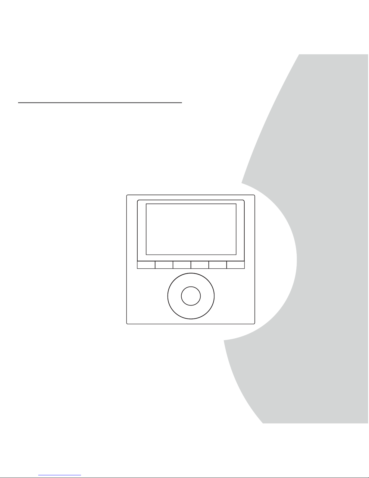
WIRED REMOTE CONTROLLER
Installation and Owner’s Manual
IMPORTANT NOTE:
Read this manual carefully before
installing or operating your wired
remote controller. Make sure to save
this manual for future reference.
MODEL:
KJR-120G1/TFBG-E(5V)(For high wall models)
KJR-120G2/TFBG-E(12V) (For Duct/Cassette/Floor ceiling models)
Page 2

Page 3

● This manual gives detailed description of the precautions that should
be brought to your attention during operation.
● To ensure the correct service of the wired controller, read this manual
carefully before using the unit.
● Keep this manual after reading for future reference.
Page 4

CONTENTS
1. SAFETY PRECAUTION....................................................................... 1
2. INSTALLATION ACCESSORY.............................................................. 2
3. INSTALLATION METHOD....................................................................4
4. APPENDIX INSTALL THE WIRE CONTROLLER KIT...............................10
5. SPECIFICATION...............................................................................16
6. WIRED CONTROLLER FEATURES AND FUNCTIONS...........................17
7. WIRED CONTROLLER DISPLAY.........................................................18
8. WIRED CONTROLLER BUTTONS.......................................................19
9. PREPARATORY OPERATION..............................................................20
10. OPERATION...................................................................................21
11. TIMER FUNCTIONS........................................................................27
12. WEEKLY TIMER.............................................................................30
13. FAULT ALARM HANDING..............................................................37
14.TECHNICAL INDICATION AND REQUIREMENT ...............................37
Page 5
1
Read the safety precautions carefully before installing the unit.
Stated below are important safety issues that must be obeyed.
Means improper handling may lead to personal death or severe injury.
Means improper handling may lead to personal injury or property loss.
WARNING
CAUTION
Please entrust the distributor or professionals to install the unit.
Installation by other persons may lead to imperfect installation, electric shock or fire.
Adhere to this installation manual.
Imporper installation may lead to electric shock or fire.
Reinstallation must be performed by professionals.
WARNING
Do not install the unit in a place vulnerable to leakage of flammable gases.Once
flammable gases are leaked and left around the wire controller, fire may occure.
Do not operate with wet hands or let water enter the wire controller. Otherwise,
electric shock may occur.
The wiring should adapt to the wire controller current. Otherwise, electric leakage or
heating may occur and result in fire.
The specified cables shall be applied in the wiring. No external force may be applied
to the terminal. Otherwise, wire cut and heating may occur and result in fire.
NOTE
Do not uninstall the unit randomly.
Random uninstalling may lead to abnormal operation, heating or fire of the air condition.
1
2
3
4
1. SAFETY PRECAUTION
Page 6
2
2. INSTALLATION ACCESSORY
Don’t install at the place where cover with heavy oil, vapor or sulfureted
gas, otherwise, this product would be deformed that would lead to
system malfunction.
Select the installation location
Preparation before installation
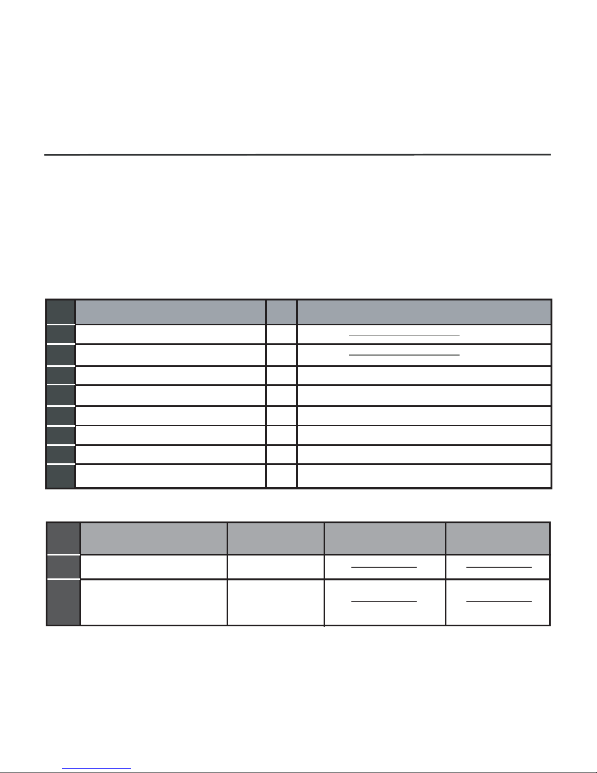
1. Please confirm that all the following parts you have been supply.
2. Prepare the following assemblies on the site.
1
2
3
4
5
3
2
M4X20 (For Mounting on the Wall)
M4X25 (For Mounting on switch box)
1
2
1
6
7
8
3
2
No. Name
Qty. Remarks
Wire controller
Installation and owner’s manual
For Mounting on the Wall
Switch box
Wiring Tube(Insulating
Sleeve and Tightening
Screw)
Qty.(embeded
into wall)
Plastic screw bars
Screws
Wall plugs
For fixing on switch box
(Optional)
No.
Name
Remarks
Specification
(only for reference)
Screws
1
1
1
Battery
The connection cable
1
1
Page 7

3
2. INSTALLATION ACCESSORY
WIRED CONTROLLER INSTALLATION PRECAUTION
1. This manual provides the wired controller installation method. Refer
to the wiring diagram in this installation manual to wire the wired
controller with the indoor unit.
2. The wired controller works in a low voltage loop circuit. Do not
connect directly to 208/230V and 460V. Do not wire this kind of wire
into a loop. Wiring clearance between the configured tubes should
range 11.81−19.69 inches (30−50 cm) or above.
3. The shielded wire of the wired controller must be properly grounded.
4. Upon finish the wire controller connection, do not employed
tramegger to detect the insulation.
Page 8
4
3. INSTALLATION METHOD
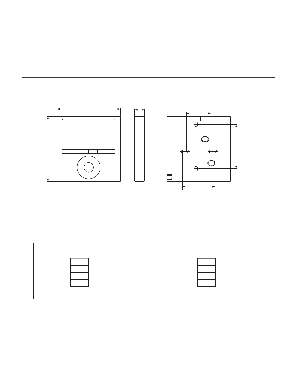
Fig 3-1
1.Wired Remote Controller Dimensions
123mm
(4.8”)
120mm
(4.7”)
18.5mm
(0.7”)
83.5mm
(3.3”)
46mm
(1.8”)
62mm
(2.4”)
Fig 3-2
2.Wiring Connection Diagram
red
black
yellow
brown
red
black
yellow
brown
Insert of the
mainboard CN40
Wire controller
Indoor unit mainboard
4-Core Shield Cable, the length
is decided by installation
-----------------------------------
-----------------------------------
-----------------------------------
-----------------------------------
Page 9
5
3. INSTALLATION METHOD
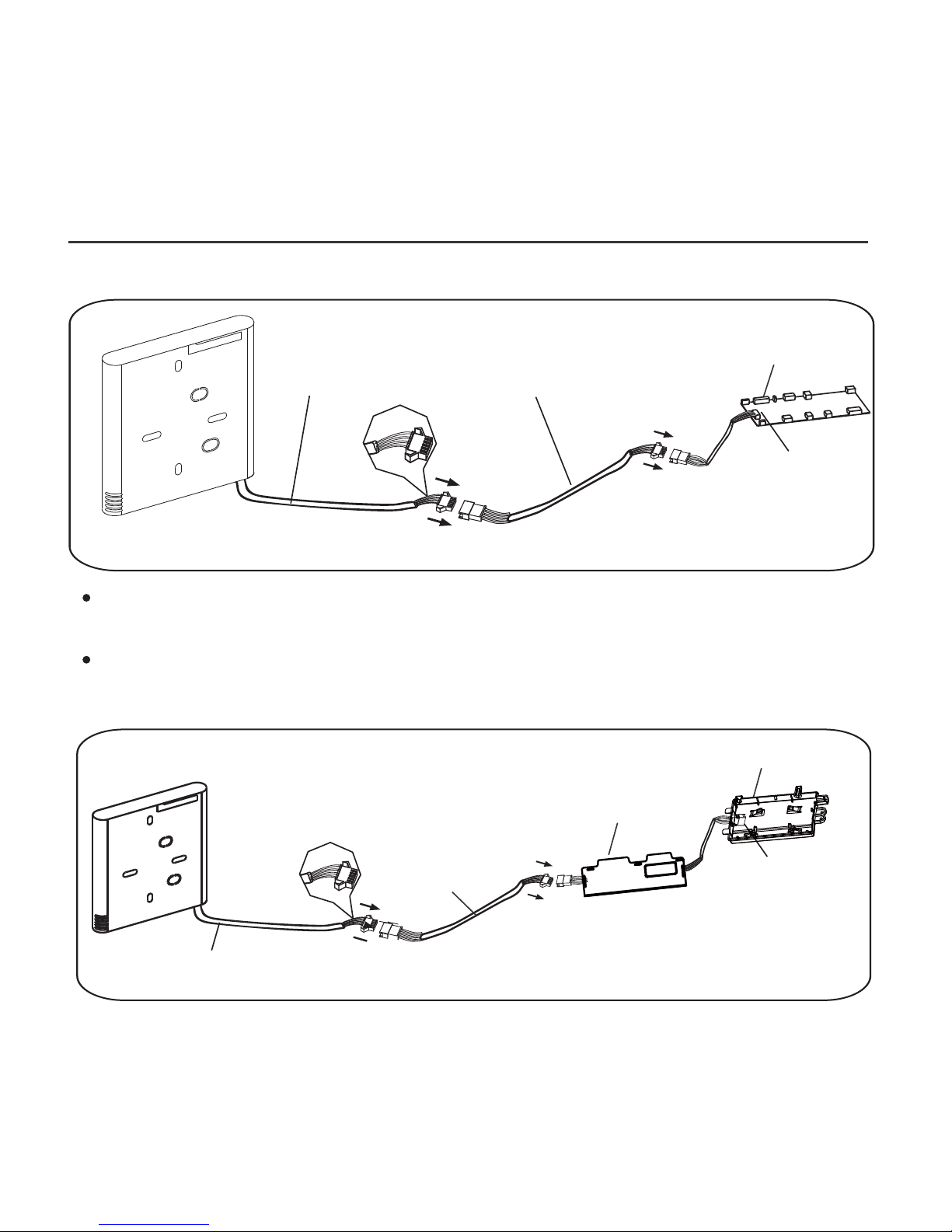
Connect the female joint of the wires group from the mainboard
with the male joint of the connective wires group. (See Fig.3-3(A))
Connect the other side of the connective wires group with the male
joint of the wires group leads from the wire controller.(See Fig.3-3(A))
Fig 3-3(A)
Mainboard
4-core shielding wire
3.Wiring figure
Model A:KJR-120G2/TFBG-E(12V)
Model B:KJR-120G1/TFBG-E(5V)
The connection cable
CN40
Fig 3-3(B)
Adapter board
Display board
4-core shielding wire
The connection
cable
CN101
Page 10
6
3. INSTALLATION METHOD
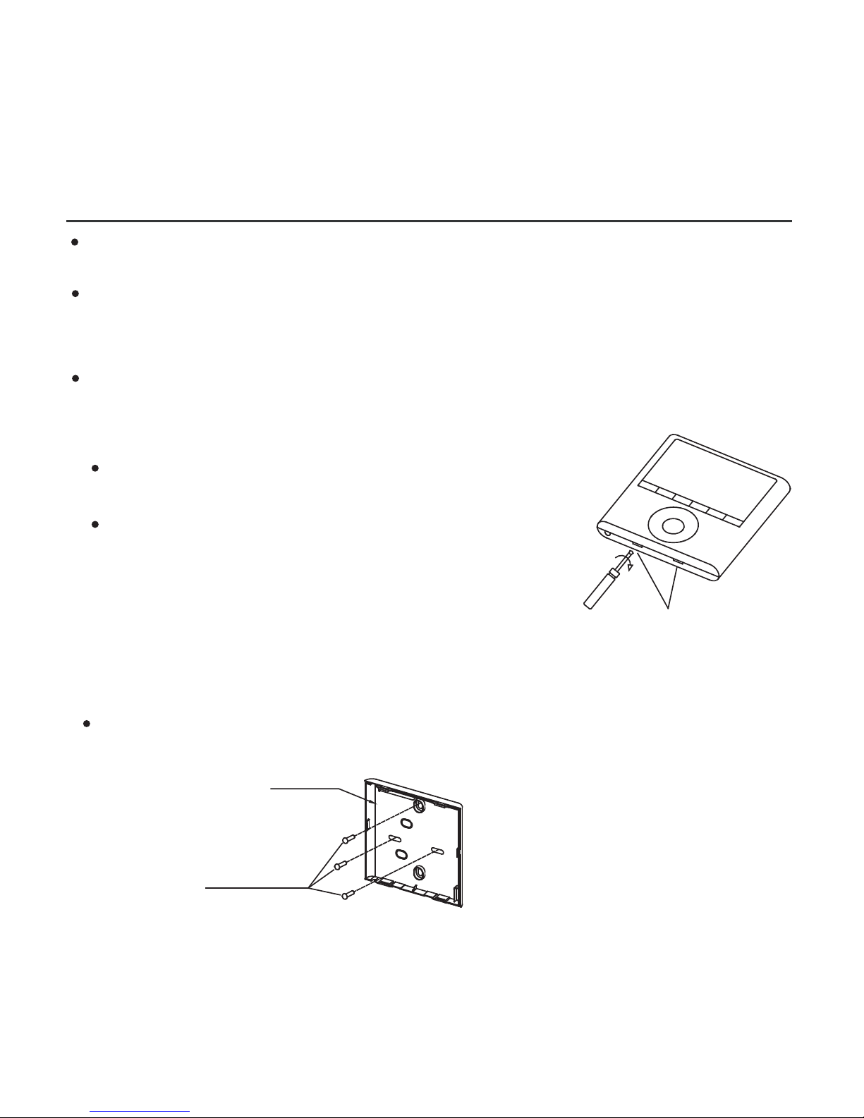
Fig 3-4
Fig 3-5
4.Wire controller upper part Remove
Insert a flat screwdriver into the slots in the
lower part of the wire controller (2 places).
Remove the upper part of the wire controller
(Fig.3-4)
For surface mounting, fasten the back plate on the wall with the 3
screws (M4x20) and plugs. (Fig.3-5)
Slots
NOTE: The PCB is mounted in the upper part
of the wired controller. Be careful not to
damage the board with the screwdriver.
5. Fasten the wire controller back plate
Back plate
Screws (M4×20)
Connect the female joint of the wires group from the adapter board
with the male joint of theconnective wires group. Next, connect the
other side of the adapter board with the displayboard. (See Fig.3-3(B))
Connect the other side of the connective wires group with the male
joint of the wires group leads from the wire controller. (See Fig.3-3(B))
Install the Adapter Board and the Display Board on the High Wall
(See the Appendix for instructions).
Page 11
7
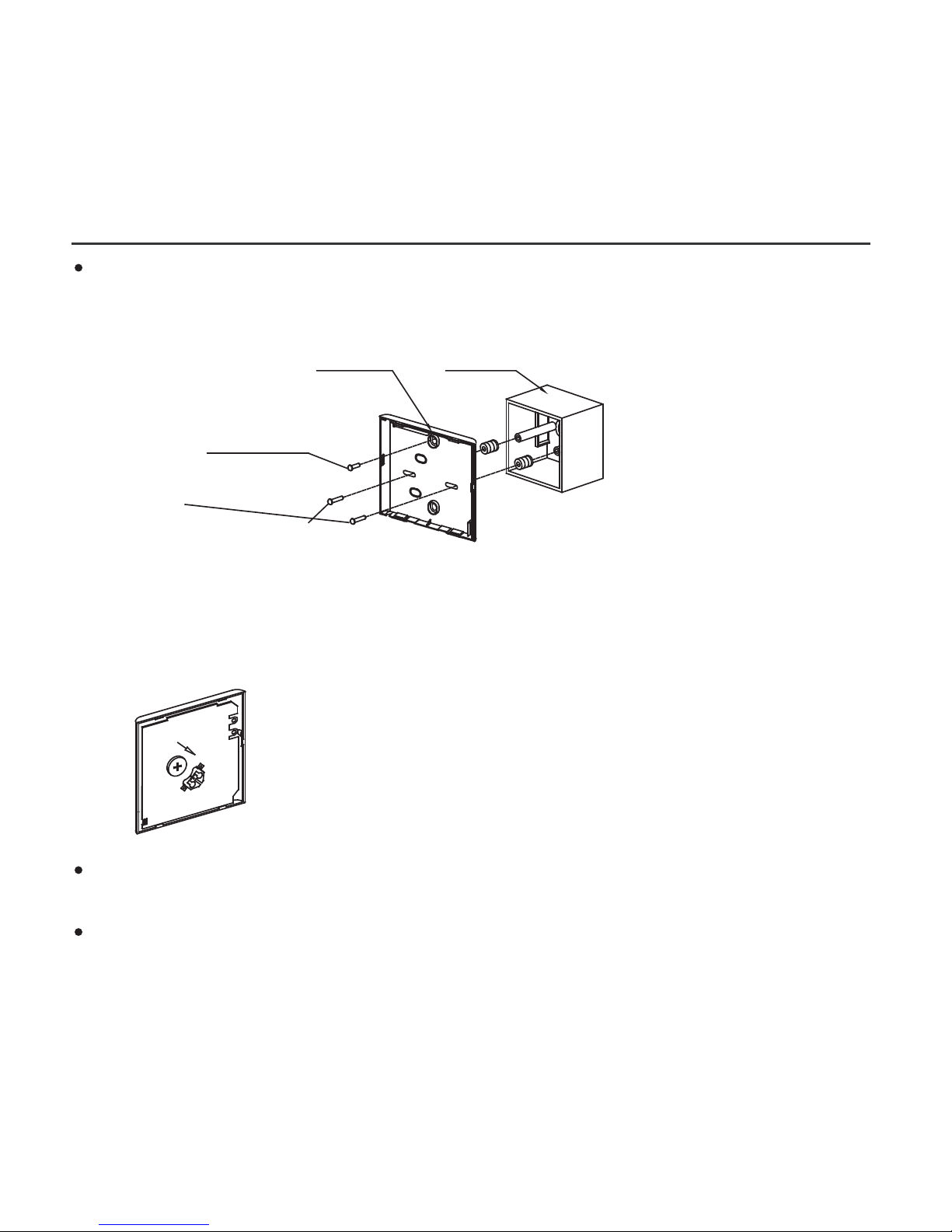
Place the battery in the unit and ensure the positive side of the
battery is in accordance with the polarity markings.(See Fig.3-7)
Set the correct time before operating. Batteries in the wired controller
can maintain the correct time during a power failure. When the power
is restored and the displayed time is not correct, replace the battery.
Fig 3-7
Fig 3-6
3. INSTALLATION METHOD
Switch box
Back plate
For switch box mounting, fasten the back plate on the switch box with
2 screws (M4x25) and fasten it on the wall with 1 screw (M4x20).
(Fig.3-6)
6. Battery installation
Screw (M4×20)
Screws (M4×25)
NOTE: Place on a flat surface. Be careful not to distort the wire
controller’s back plate by over−tightening the mounting screws.
Page 12
8
3. INSTALLATION METHOD
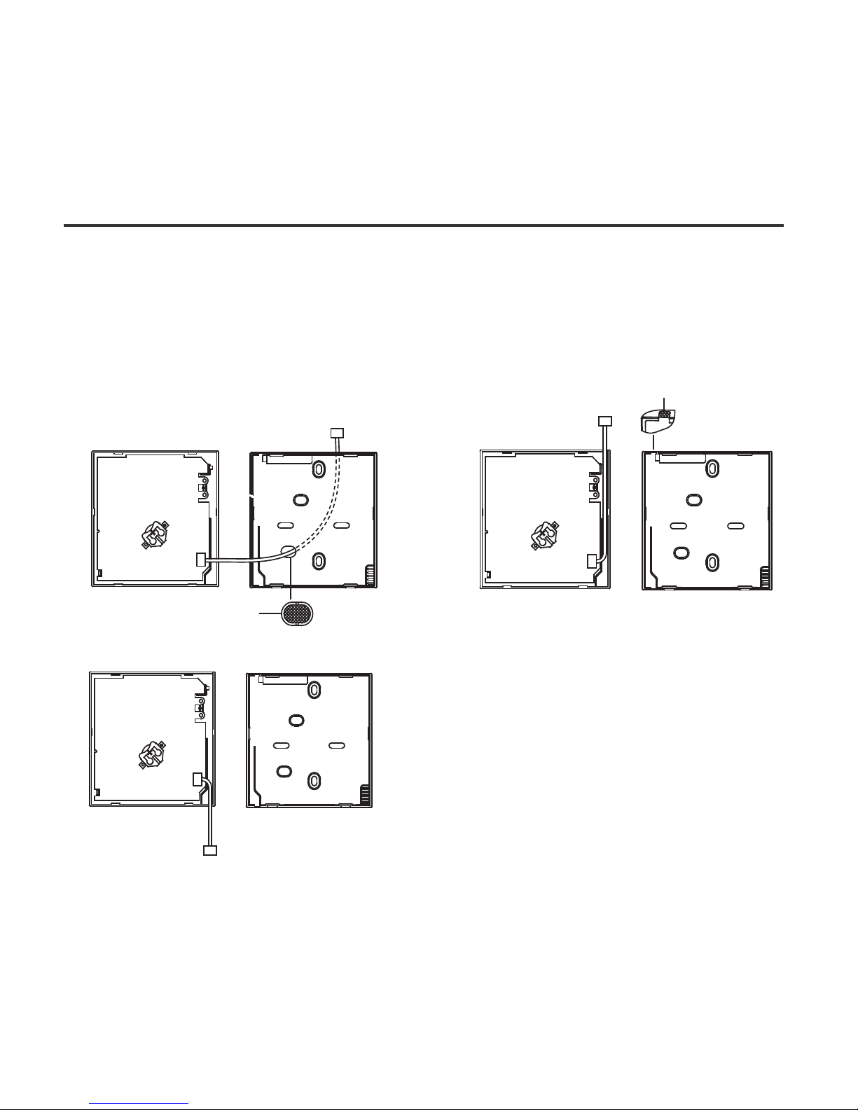
7. Wire the indoor unit
1 from the rear;
2 from the bottom;
3 from the top;
There are three methods:
4. Notch the part for the wiring to pass through with a nipper tool.
PCB
PCB
PCB
1
1
1
2
3
Page 13

9
Fig 3-8
3. INSTALLATION METHOD
Putty
Putty
Putty
Trap
Trap
Trap
Fig 3-9
IMPORTANT: All the pictures
in this manual are for
illustration purposes only.
Your wire controller may
differ slightly.
8. Reattach the wire controller’s upper part
While adjusting and mounting the upper case, avoid clamping the
wiring during installation. (Fig 3-9)
NOTE: DO NOT allow water to enter the remote control.
Use the trap and putty to seal the wires.
Page 14
10
4. APPENDIX
INSTALL THE WIRE CONTROLLER KIT
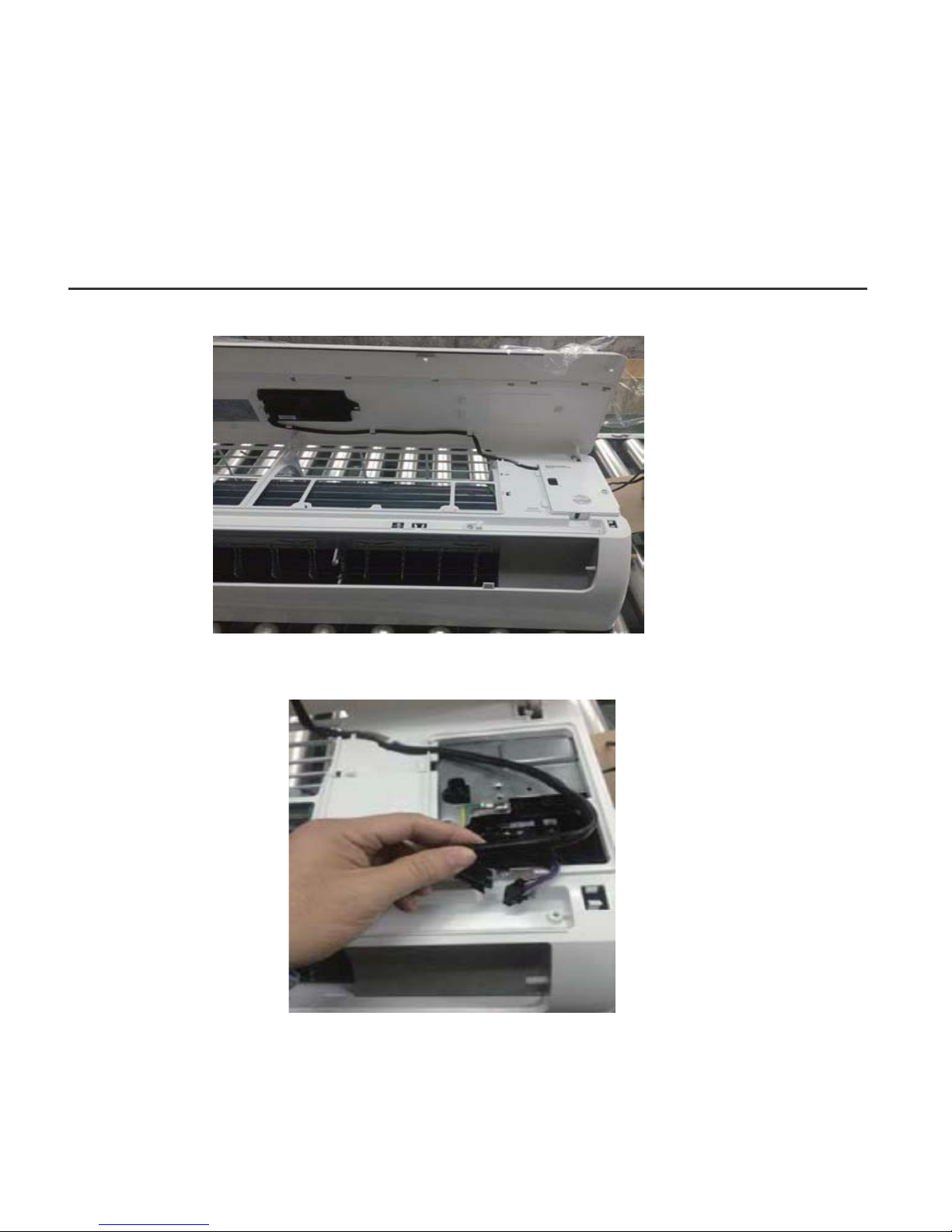
1. Open the front panel.
2. Disconnect the wire from the main controller board.
Page 15
11
4. APPENDIX
INSTALL THE WIRE CONTROLLER KIT
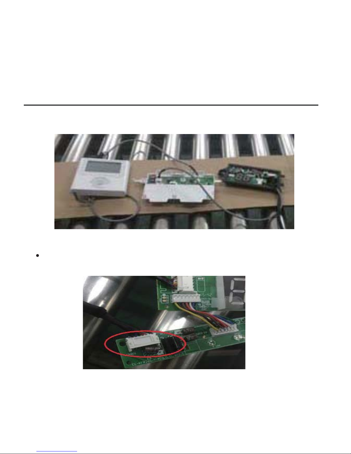
3. Identify the components. From left to right, the wired controller,
convert board and the display board.
4. Identify connections on the Display Board.
CN201 is the display board connection to the main board wire
(on the display board).
Page 16
12
4. APPENDIX
INSTALL THE WIRE CONTROLLER KIT
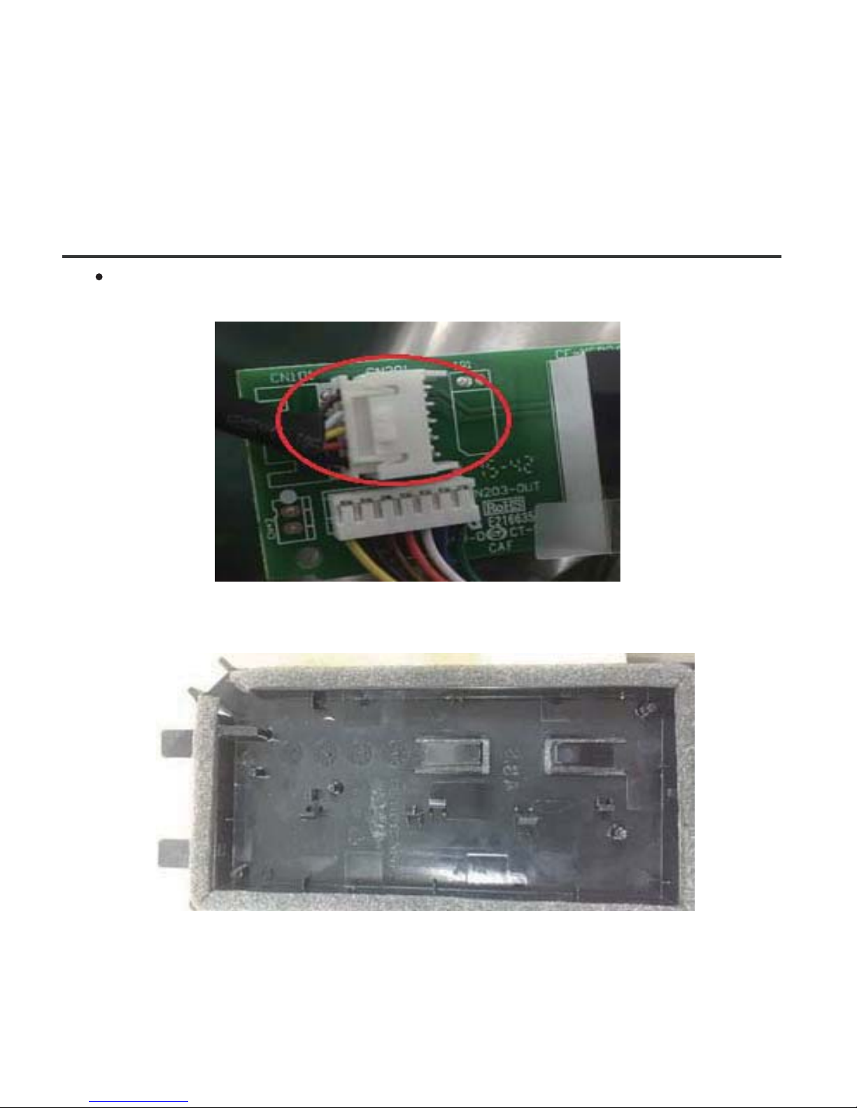
CN101 is the display board connection to the convert board wire
(on the display board).
5. Uninstall the display board from the front panel. Keep the display
board holder.
Page 17
13
4. APPENDIX
INSTALL THE WIRE CONTROLLER KIT
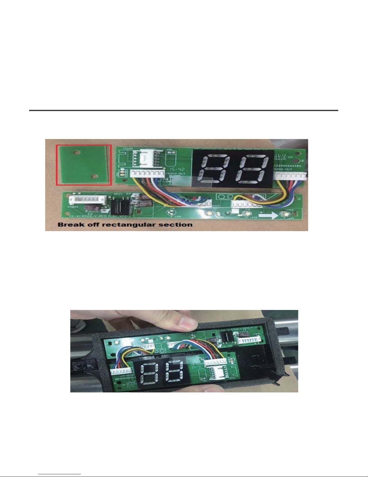
6. Carefully bend and break off the rectangular section (upper left
section with two diagonal holes) from the display board.
NOTE: Break off the upper left hand rectangle (section with the two
holes marked with a red rectangle).
7. Replace the old display board (for the New Display board provided)
and secure with the clips. To uninstall the clips, push the clips inward.
NOTE: There are 4 clips just above the numeric display (88) which run
the length of the holder.
Page 18
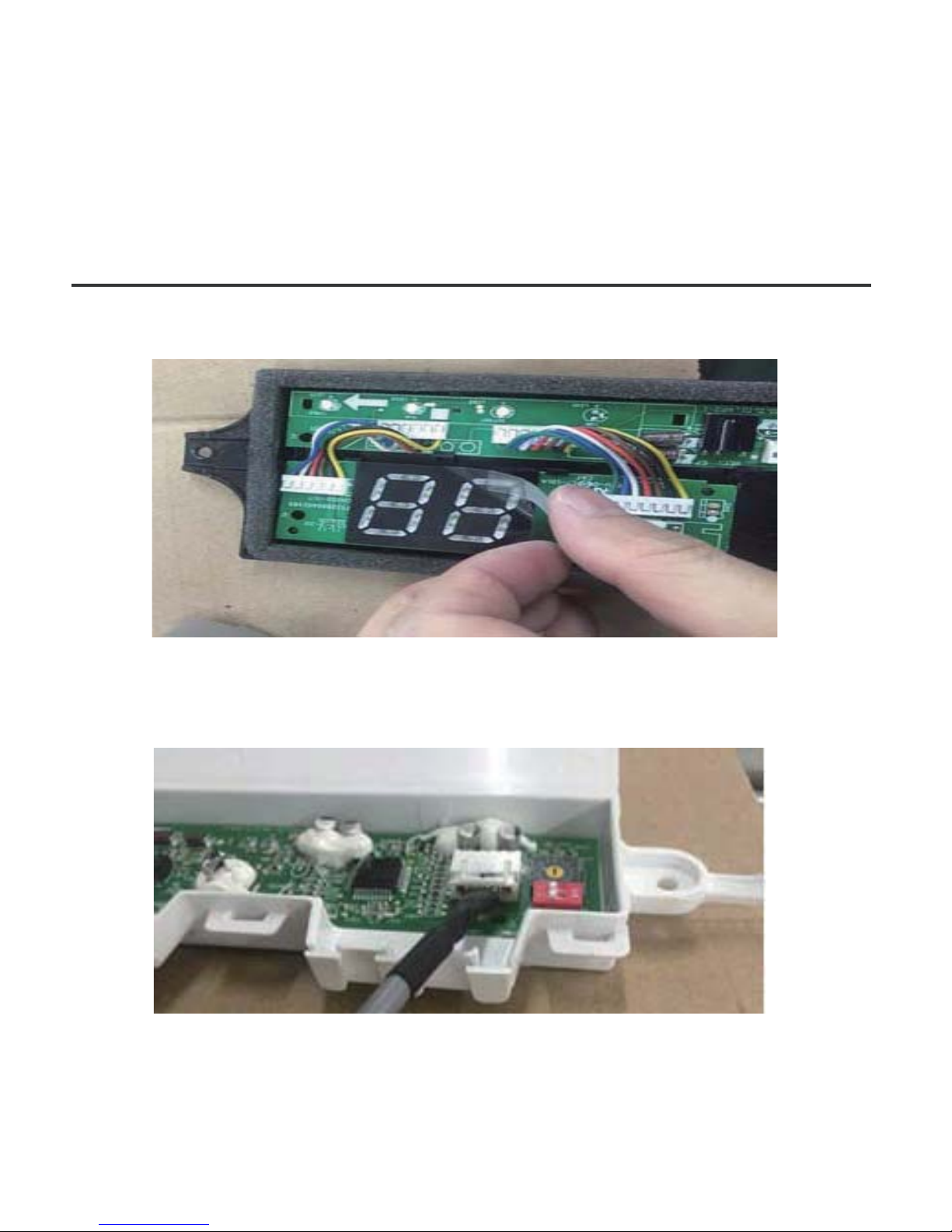
14
4. APPENDIX
INSTALL THE WIRE CONTROLLER KIT
8. Before assembling mounting back on the Front Panel, remove the
display board’s screen cover.
9. Connect the Wires to the Adaptor Board.
a. Connect the wire coming from the Display board to the Convert
Board (this connection consists of 5 wires).
Page 19
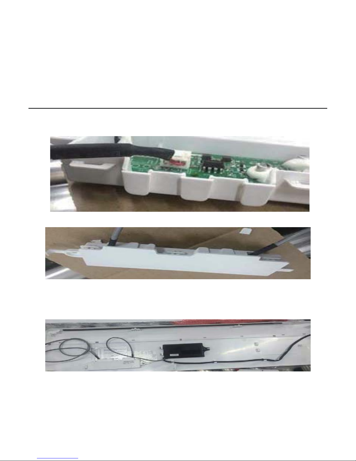
15
4. APPENDIX
INSTALL THE WIRE CONTROLLER KIT
b. Connect the wire coming from the Wired Remote Controller to
the Convert Board (this connection consists of 4 wires).
10. Once the ports are connected, install the cover.
11. Mount the new display board and convert board to the Front Panel.
12. Connect the wired remote controller to the display board and the
convert board.
13. Connect the wire from the main controller board (see Fig 3-2).
Page 20
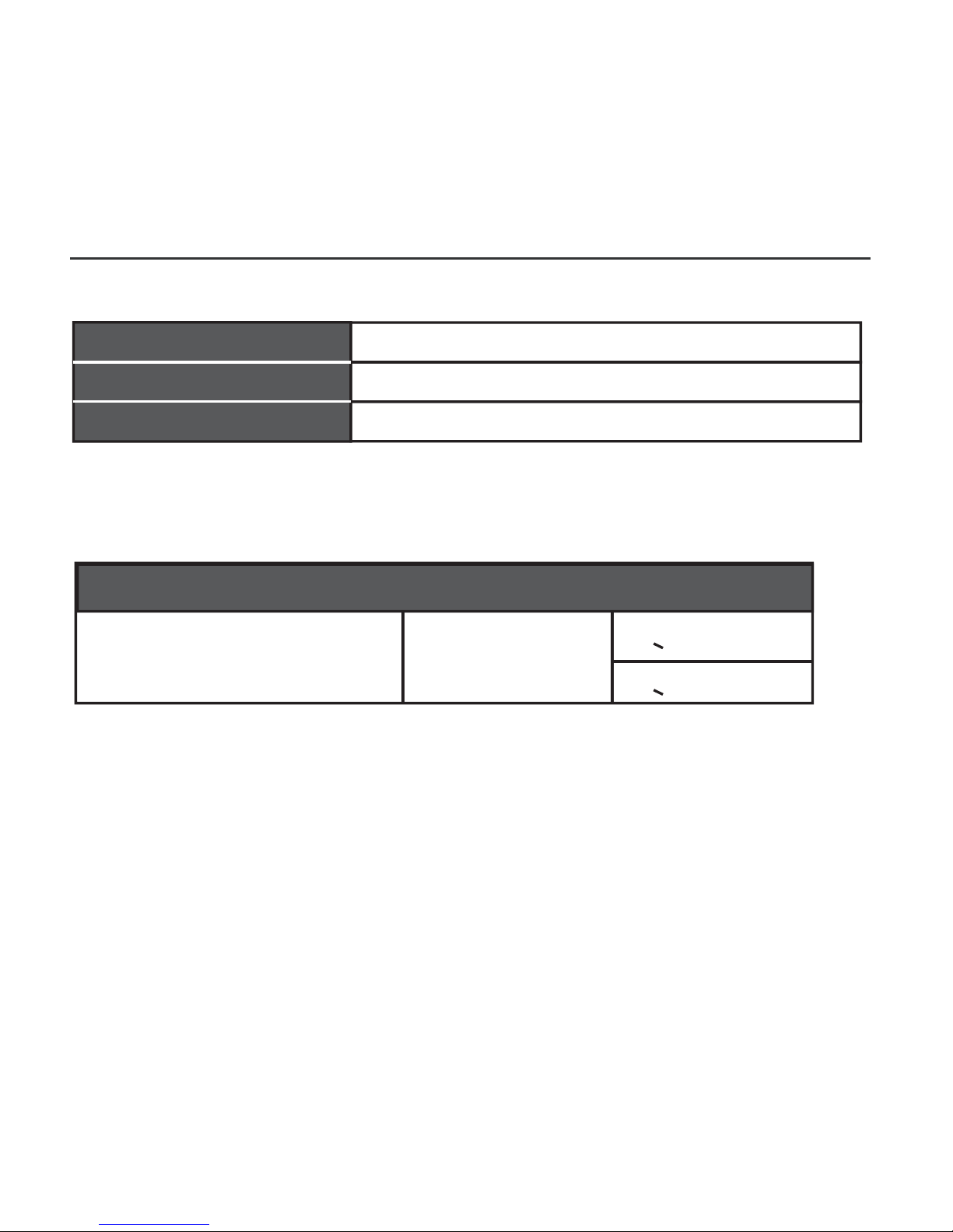
5. SPECIFICATION
DC 5V/DC 12V
23~110℉(-5~43℃)
RH40%~RH90%
Input voltage
Wiring type
Size
Total length
Ambient temperature
Ambient humidity
16
Wiring specifications
Shielded vinyl cord or cable
0.029 in-0.74mm
(0.75-1.25mm )
<66 ft (20m)
2
<164 ft (50m)
Page 21
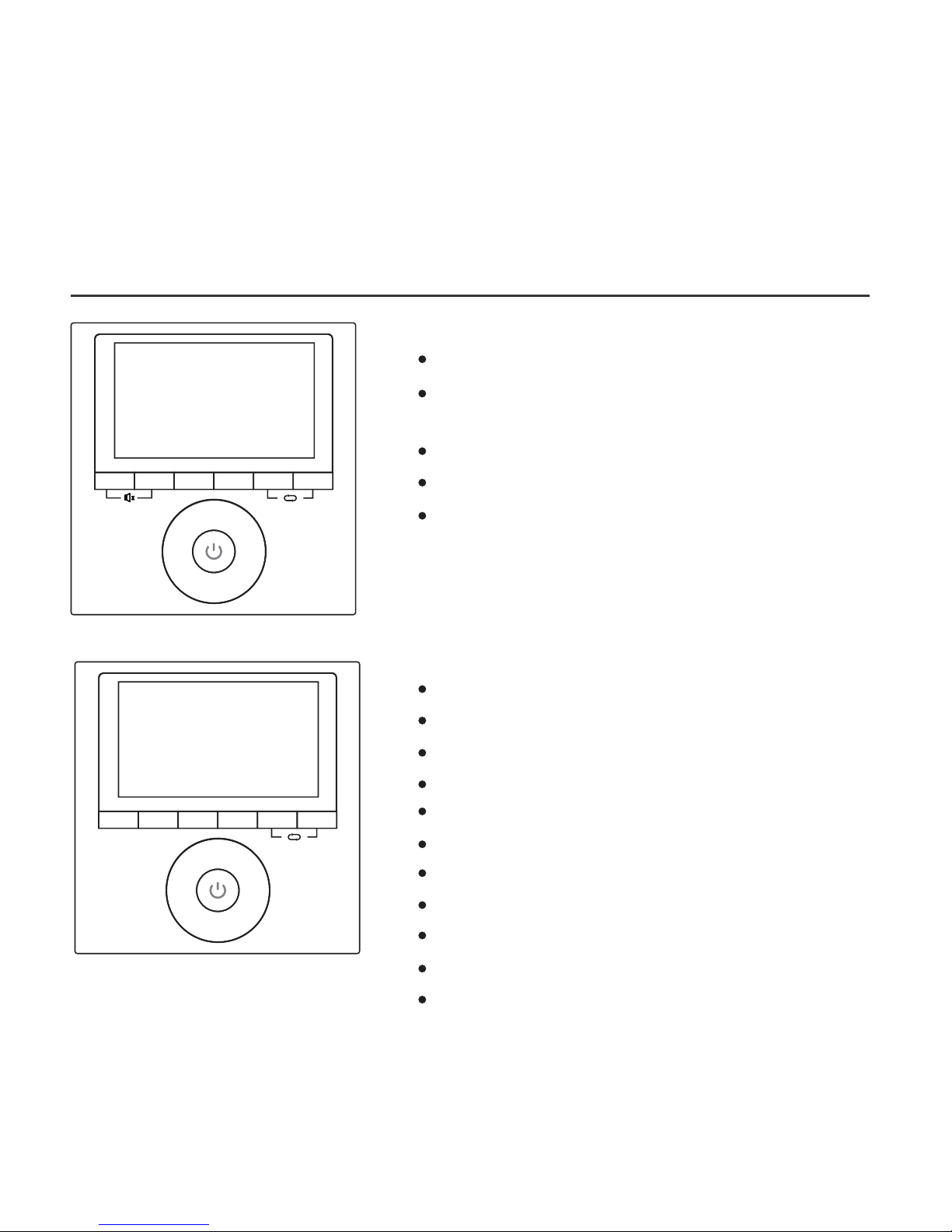
17
6. FEATURE AND FUNCTION OF THE WIRED
CONTROLLER
Mode: choose Auto-Cool-Dry-Heat-Fan
Fan speed: Auto-Low-Med-High
Swing(on some models)
Timer ON/OFF
Temp setting
Weekly Timer
Follow me
Child Lock
LCD Display
Clock
Panel function (on some models)
Feature:
LCD display.
Malfunction code display: displays the
error code (helpful for servicing)
4-way wire layout design.
Room temperature display.
Weekly Timer
Swing Timer
Day off/Del
Confirm Back/Turbo
Copy/
Follow me
Mode
Fan speed
(Lock)
-
+
MODEL: KJR-120G1/TFBG-E(5V)
MODEL: KJR-120G2/TFBG-E(12V)
℉
℃
Swing Timer
Day off/Del
Confirm Back/Turbo
Copy/
Follow me
Mode
Fan speed
(Lock)
-
+
℉
℃
Function:
Page 22
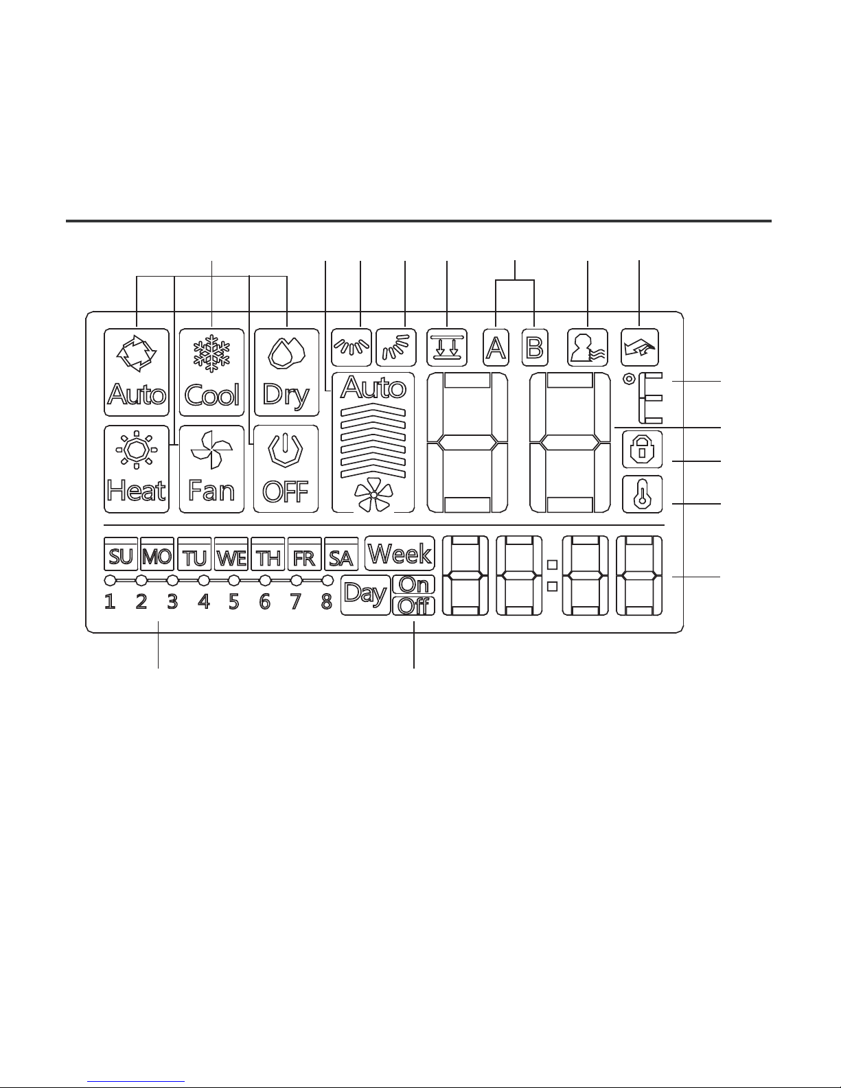
7. WIRED CONTROLLER DISPLAY
1. Operation mode indicator
2. Fan speed indicator
3. Left-right swing indicator
4. Up-down swing indicator
5. Faceplate function indicator
6. Main unit and secondary unit
indicator
7. Follow me function indicator
12345
7
9
10
11
12
13
15 14
8. Turbo/Auxiliary Heat function indicator
9. °C / °F indicator
10. Temperature display
11. Lock indicator
12. Room temperature indicator
13. Clock display
14. On/Off timer
15. Timer display
18
68
Page 23
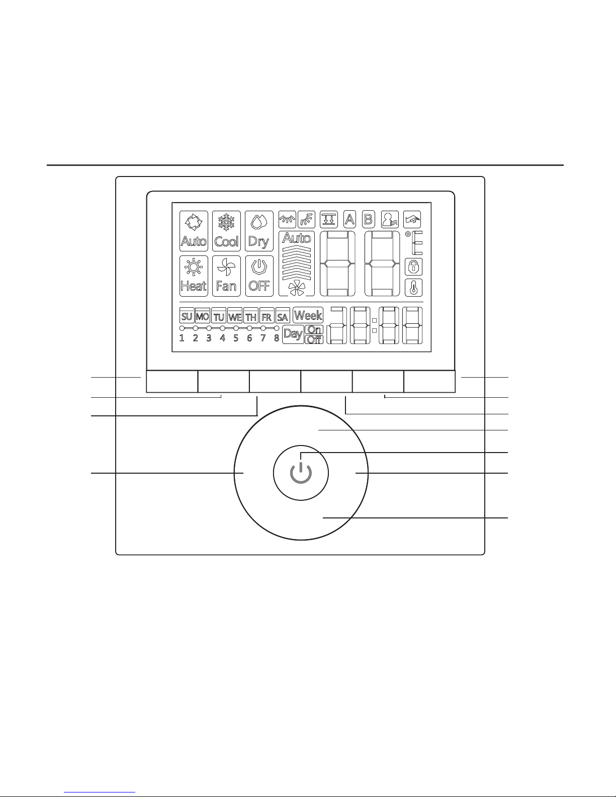
8. WIRED CONTROLLER BUTTONS
1
1. Mode
2. Power
3. Adjust
4. Fan Speed
5. Swing
6. Timer
7. Day Off/Del
8. Copy/Follow me
9. Back/Turbo
10. Confirm
19
Swing Timer
Day off/Del
Confirm Back/Turbo
Copy/
Follow me
Mode
Fan speed
(Lock)
-
+
2
3
4
3
5
6
7
8
9
10
Page 24
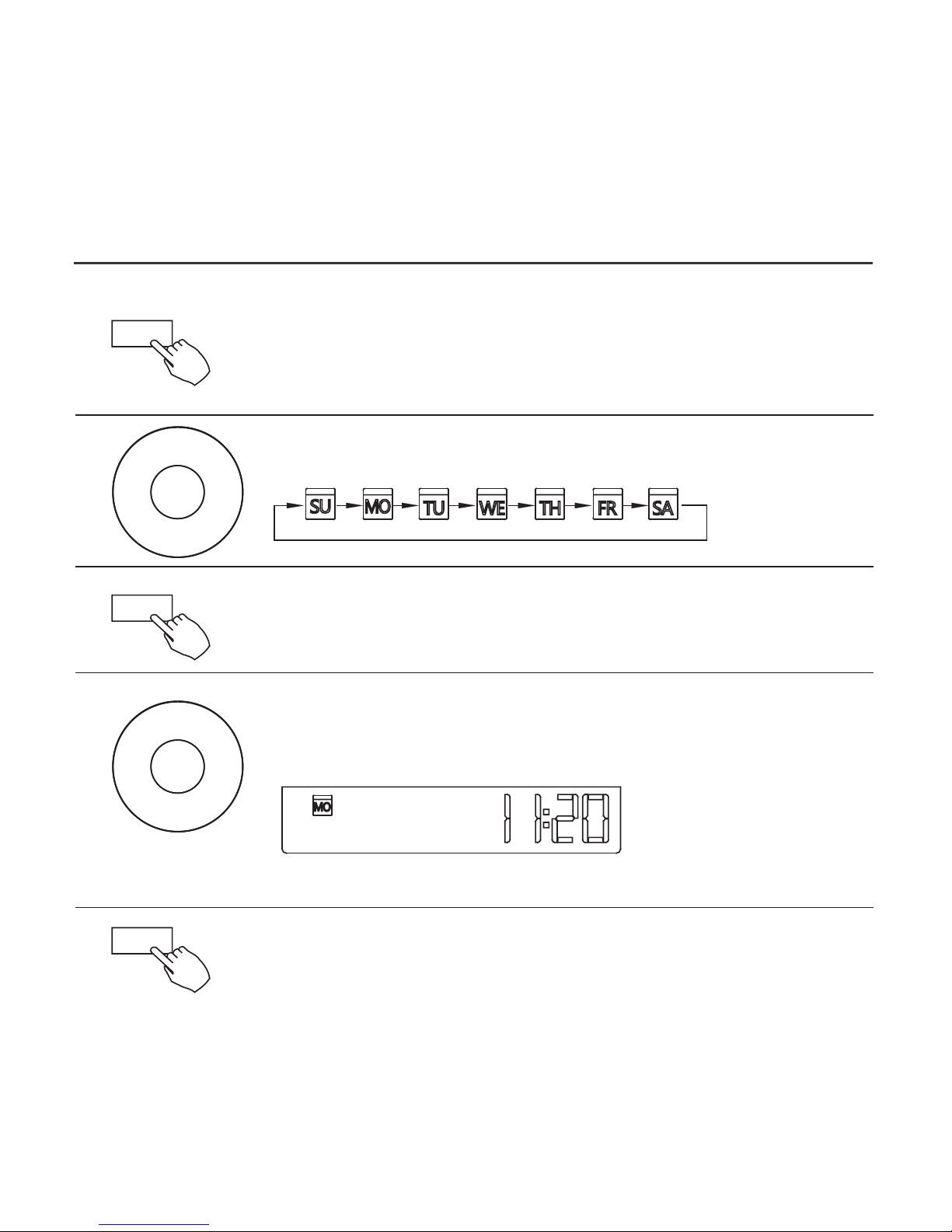
9. PREPARATORY OPERATION
Press TIMER for 3s or more. The timer displays flashes.
Press + or − to set the current time. Press repeatedly to
adjust the current time in 1 minute increments.
Press and hold to adjust the current time.
ex.Monday AM 11:20
1
2
3
4
5
Press + or − to set the date. The selected date flashes.
Date setting is complete and the time setting is ready after
pressing TIMER or if nothing is pressed in 10 seconds.
The setting is complete after pressing TIMER or if no
button is pressed for 10 seconds.
Set the current day and time
20
Timer
-
+
Timer
-
+
Timer
Page 25
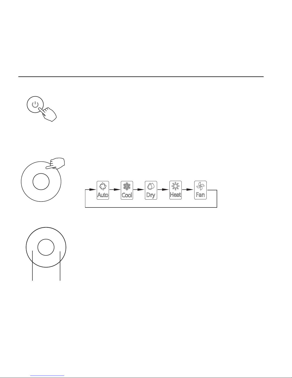
10. OPERATION
To start/stop operation
Press the Power button.
To set the operation mode
Press MODE to set the operation mode.
(Heat function is invalid for cool only type unit)
Room temperature setting
Press + or − to set the room temperature. Indoor
Setting Temperature Range:
62~86℉(17~30℃)/62~88℉(17~31℃(depending
on models)).
Lower Raise
Operation mode setting
21
Mode
-
+
Page 26
10. OPERATION
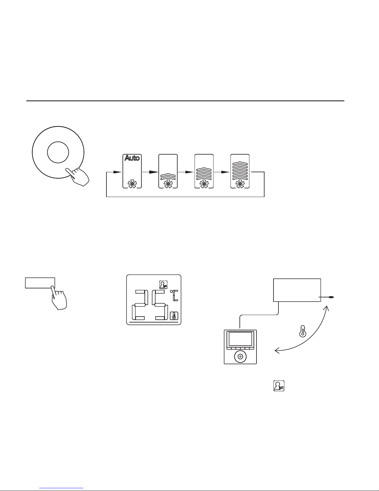
Fan speed setting
Press FAN SPEED to set the fan speed
NOTE: This function is unavailable in the AUTO or DRY
modes.
Room temperature sensor selection
Indoor Unit
Press FOLLOW ME to select whether the room temperature
is detected at the indoor unit or at the wired controller.
NOTE: When the FOLLOW ME function indication appears,
the room temperature is detected at the wire remote controller.
22
Fan speed
(Lock)
Copy/
Follow me
Page 27
10. OPERATION
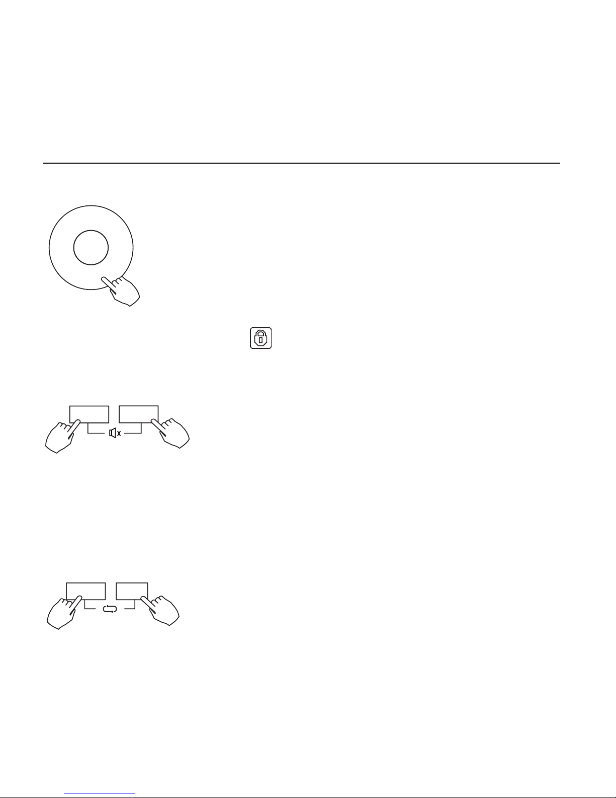
Child lock function
Press LOCK for 3 seconds to activate the
CHILD LOCK feature and lock all buttons on
the wired controller. Press again for 3 seconds
to deactivate.
NOTE: When the child lock function is activated,
the lock image appears.
keypad tone setting
Press SWING and TIMER simultaneously for 3
seconds to disable the keypad tone. Press the
buttons again for 3 seconds to enable the
keypad tone.
23
°C & °F scale selection (on some models)
Press BACK and COPY simultaneously for 3
seconds to alternate the temperature display
between the ℉&℃ scale.
Fan speed
(Lock)
Back/Turbo
Copy/
Follow me
Swing
Timer
℉
℃
Page 28
10. OPERATION
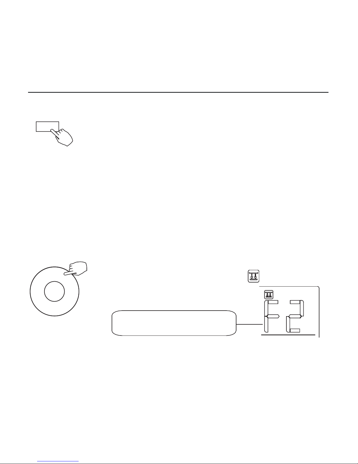
Lift panel function (only for some cassette specific panel)
1.When the unit is off,Press the Mode button long to
activate the lift panel function.The mark will flash.
2. Press the button + and - to control the lift and drop of the panel.
Pressing the + button can stop the panel,while it is dropping.
Pressing the - button can stop the panel,while it is lifting.
The F2 mark appears when
the panel is adjusted.
24
Mode
Turbo/Auxiliary Heat function (on some models)
Press TURBO to activate/deactivate the Turbo/Auxiliary
Heat function. The turbo function sets the unit to reach
the user’s present temperature in the shortest amount of
time possible.
When the user presses TURBO in the COOL mode, the
unit sets to the highest fan speed setting to jump−start
the cooling process.
When the user presses TURBO in the HEAT mode, for
units with AUX. HEAT, the AUX. HEAT activates and
jump−starts the heating process.
Back/Turbo
•
•
•
Page 29

10. OPERATION
2 Left-Right swing
Press the Swing button long to start Left-Right swing function.
Press it again to stop.
When the Left-Right swing function is activated, the mark appears.
25
Swing
1 Up-Down swing
Press the Swing button to start up-down swing function.
Press it again to stop.
When the Up-Down swing function is activated,the mark appears.
Swing
Swing function
(For the unit with left & right auto swing function only)
Page 30
10. OPERATION
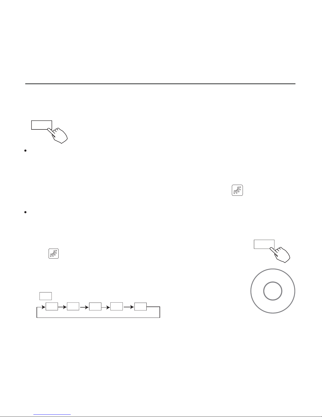
Up-Down airflow direction and swing
1.Every time the user presses SWING, the louver swings six degrees.
2.Press and hold SWING for 2 seconds, it changes to the
UP−DOWN SWING mode. Press SWING again to stop.
When the Up-Down swing function is activated,the mark appears.
(Not applicable to all the models)
The operation can refer to the following instructions for the unit with
four Up-Down louvers can be operated individually.
-0
-1
-2
-3
-4
1.Press the Swing button to activate the Up-Down
adjusting louver function.
The mark will flash.(Not applicable to all the models)
2.Pressing the button “+” or“-” can select the movement
of four louvers.Each time you push the button,the wire
controller select in a sequence that goes from:(the icon
means the four louvers move at the same time.)
3. And then use Swing button to adjust the Up-Down airflow direction
of the selected louver.
-0
26
Use SWING to adjust the up and down airflow direction.
Swing function
(For the unit without left & right auto swing function models)
Swing
Swing
-
+
Page 31
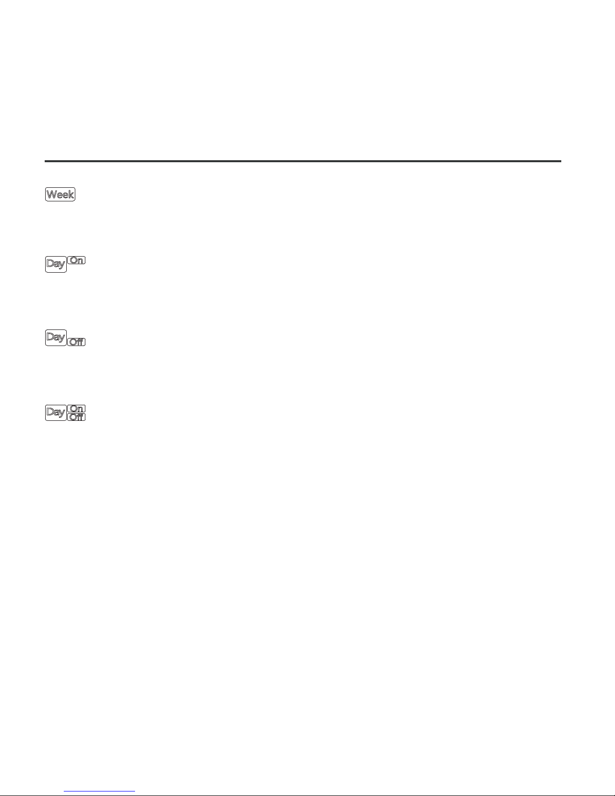
11. TIMER FUNCTIONS
WEEKLY timer
Use to set the operating times for each day of the week.
On timer
Use to start the air conditioner operation. The timer operates
and the air conditioner operation starts after the time has passed.
Off timer
Use to stop the air conditioner operation. The timer operates
and the air conditioner operation stops after the time has passed.
On and Off timer
Use to start and stop the air conditioner operation. The timer
operates and the air conditioner operation starts and stops after
the time has passed.
27
Page 32
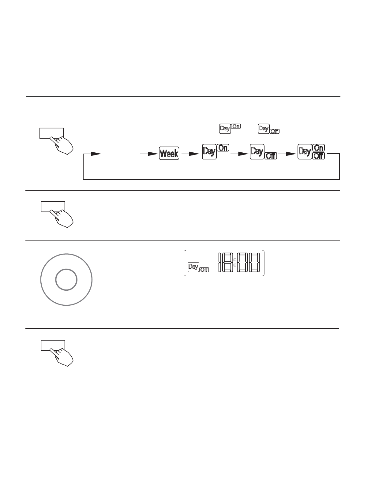
11. TIMER FUNCTIONS
To set the On or Off TIMER
Press Timer to select the or .
No display
1
2
Press Confirm and the Clock display flashes
Press Confirm again to finish the settings.
3
Press + or − to set the time. After the time is set, the
timer starts or stops automatically.
ex.Off timer set at PM 6:00
4
28
-
+
Confirm
Timer
Confirm
Page 33
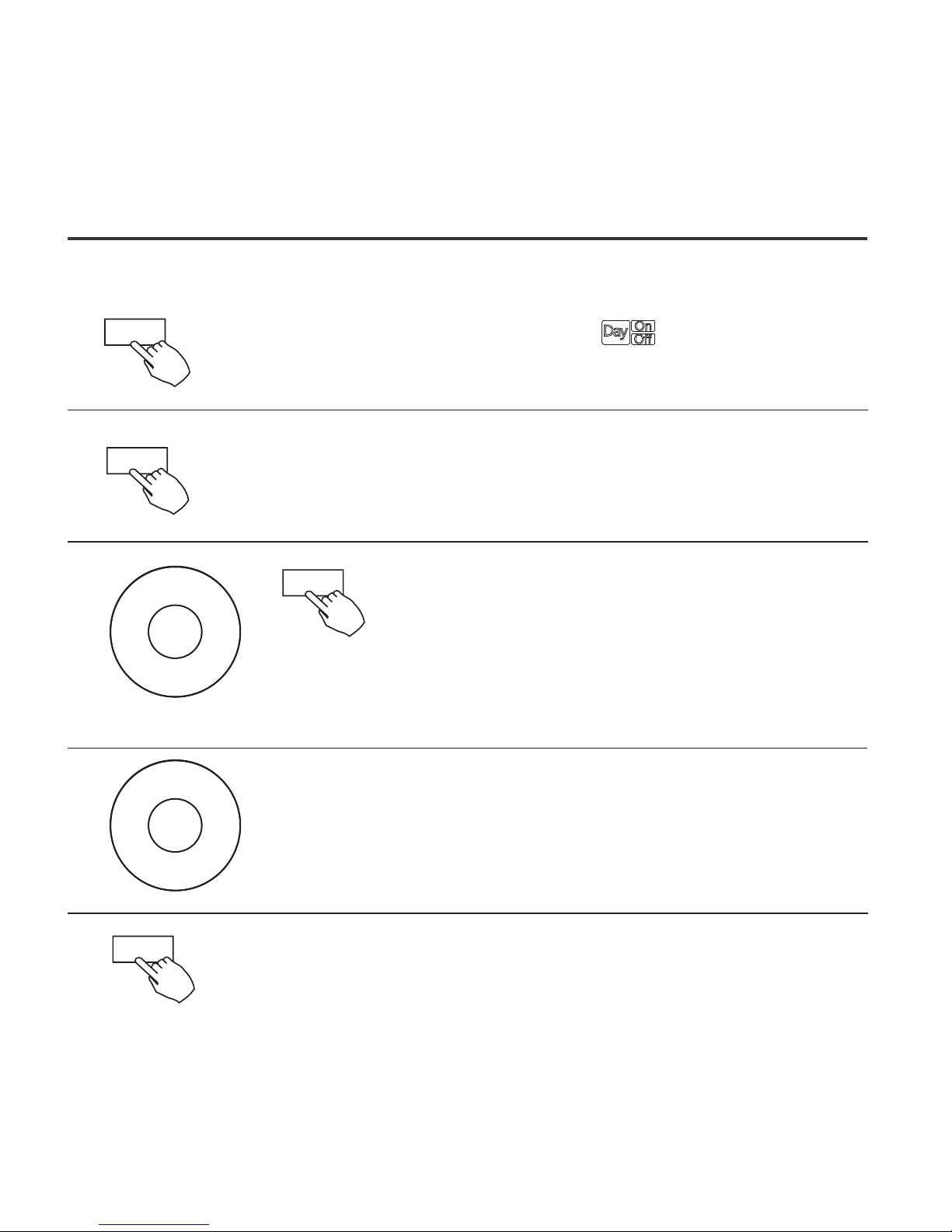
11. TIMER FUNCTIONS
Press Confirm to finish the setting.
To set the On and Off TIMER
Press Timer to select the .
1
2
Press Confirm and the Clock display flashes.
3
Press the button + or - to set the On timer and
then press Confirm.
4
Press + or - to set the Off timer.
5
29
Timer
Confirm
Confirm
-
+
-
+
Confirm
Page 34
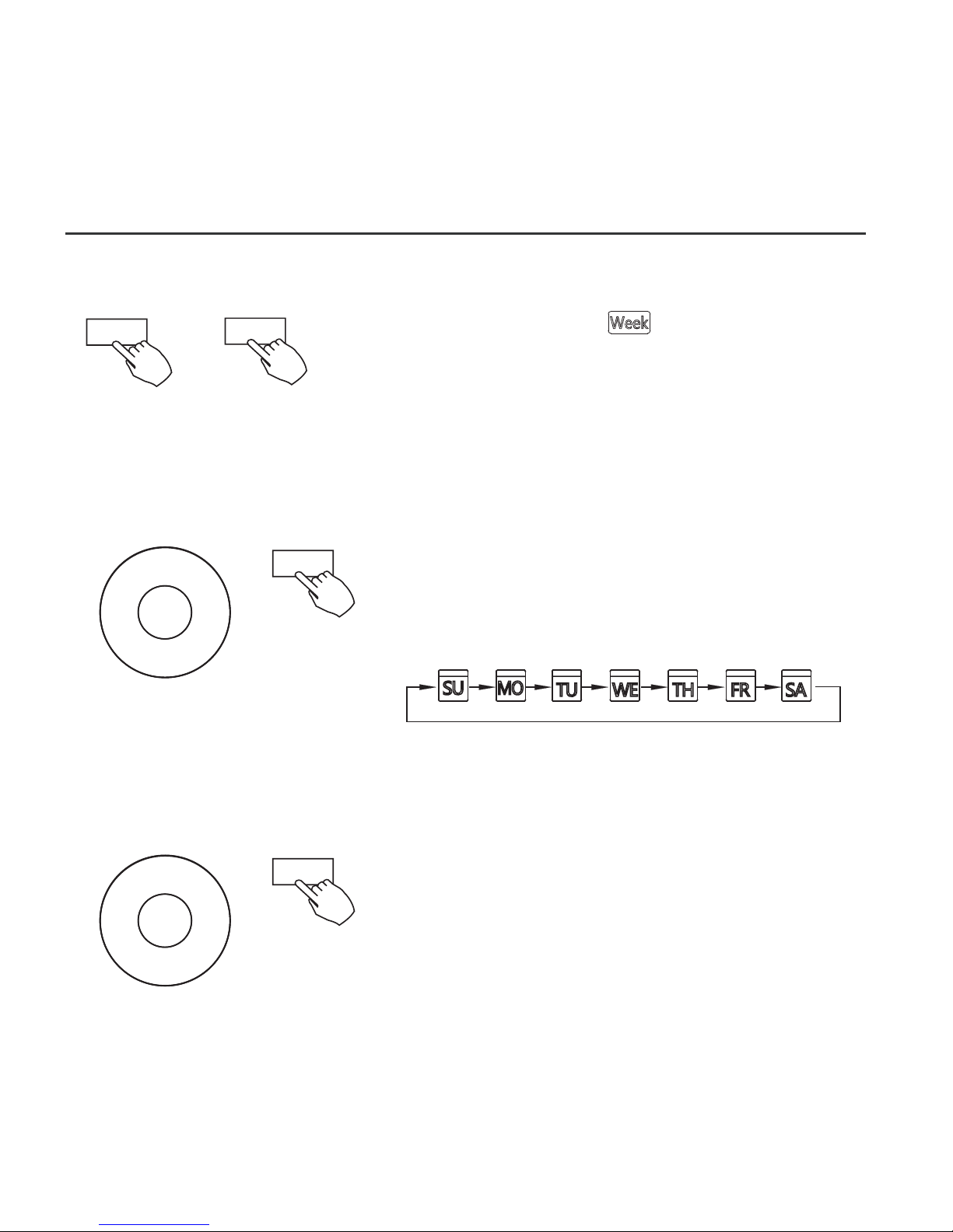
12. WEEKLY TIMER
Weekly timer setting
Press Timer to select the and press Confirm.
1
Press + or − to select the day of the week
and then press CONFIRM.
2
Day of the week setting
Press + and − to select the setting time.
The setting time, mode, temperature and
fan speed appear on the LCD. Press
CONFIRM to enter the setting time process.
ON timer setting of timer setting 1
3
30
Timer
Confirm
-
+
Confirm
-
+
Confirm
Page 35
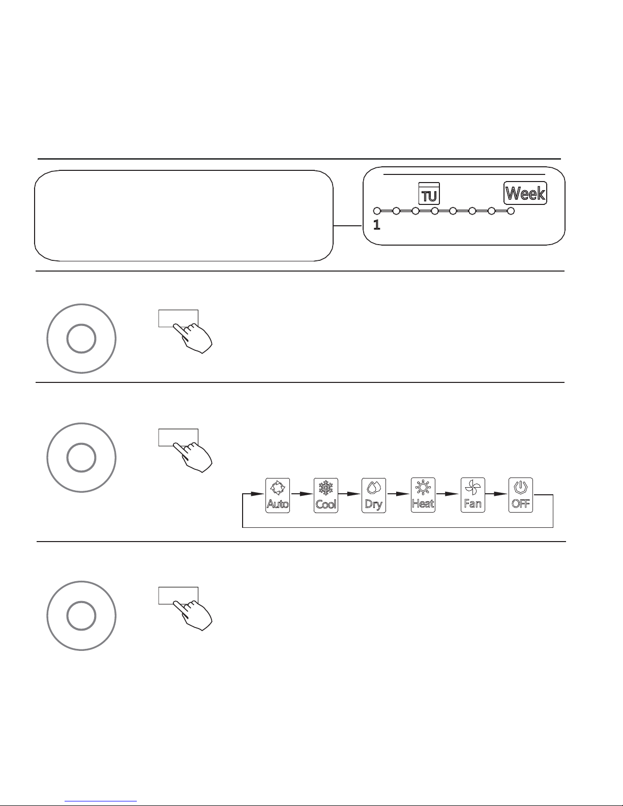
31
12. WEEKLY TIMER
ex.Tuesday time scale 1
IMPORTANT: Up to 8 scheduled events
can be set on one day. Various events
can be scheduled in either MODE,
TEMPERATURE and FAN speeds.
4
Time setting
Press + and − to set the time then press
CONFIRM.
5
Operation mode setting
Press + and − to set the operation mode
then press CONFIRM.
6
Room temperature setting
-
+
Confirm
Press + and − to set the room temperature
then press CONFIRM.
NOTE: This setting is unavailable in the FAN
or OFF modes.
-
+
Confirm
-
+
Confirm
Page 36
32
12. WEEKLY TIMER
NOTE: The weekly timer setting can be returned to the
previous step by pressing BACK. The current setting is
restored. The controller will not save the weekly timer
settings if there is no operation within 30 seconds.
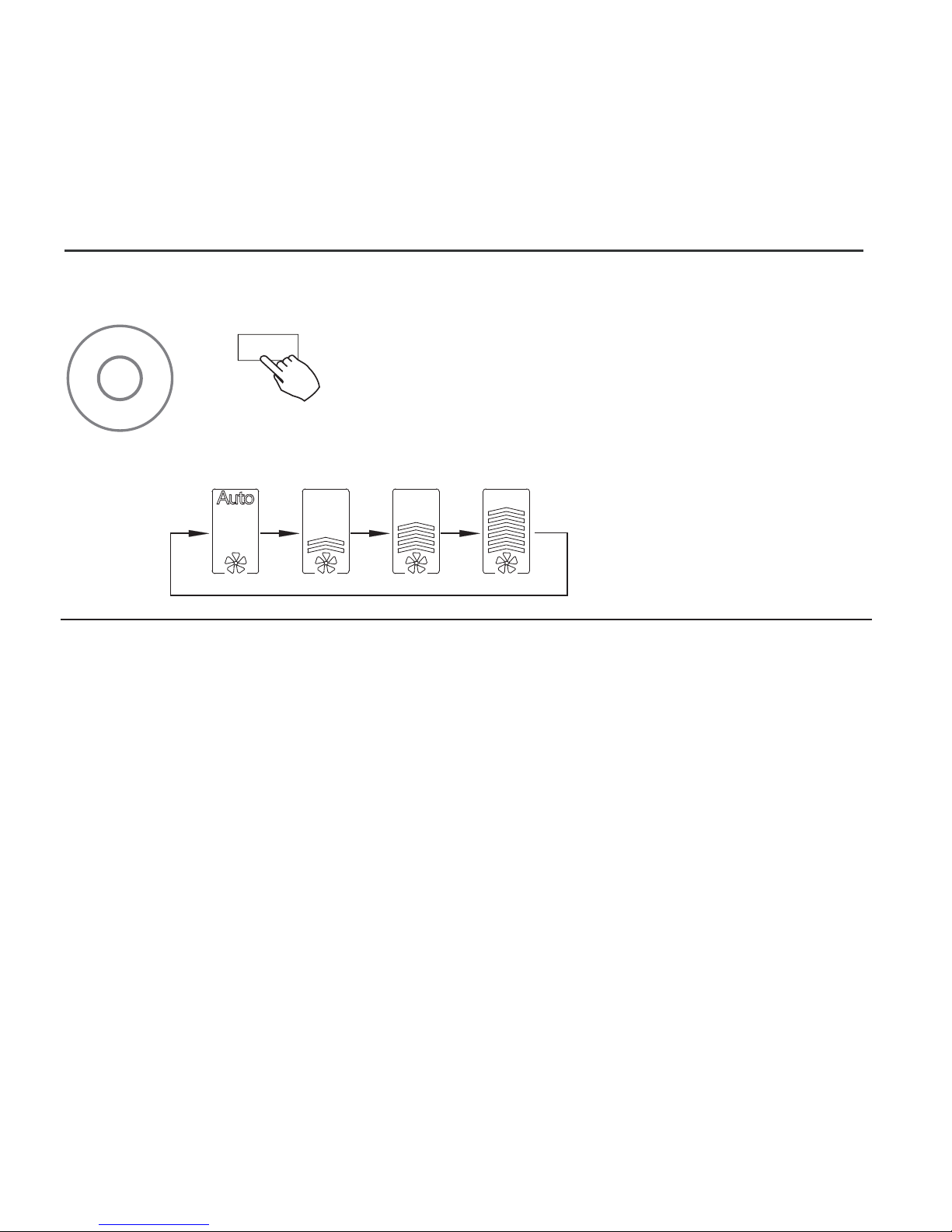
7
Fan speed setting
Different scheduled events can be set by repeating
steps 3 through 7.
Additional days, in a one week period, can be set
by repeating steps 3 through 8.
Press + and − to set the fan speed then press
CONFIRM.
NOTE: This setting is unavailable in the AUTO,
DRY or OFF modes.
8
9
-
+
Confirm
Page 37
12. WEEKLY TIMER
33
Timer
Timer
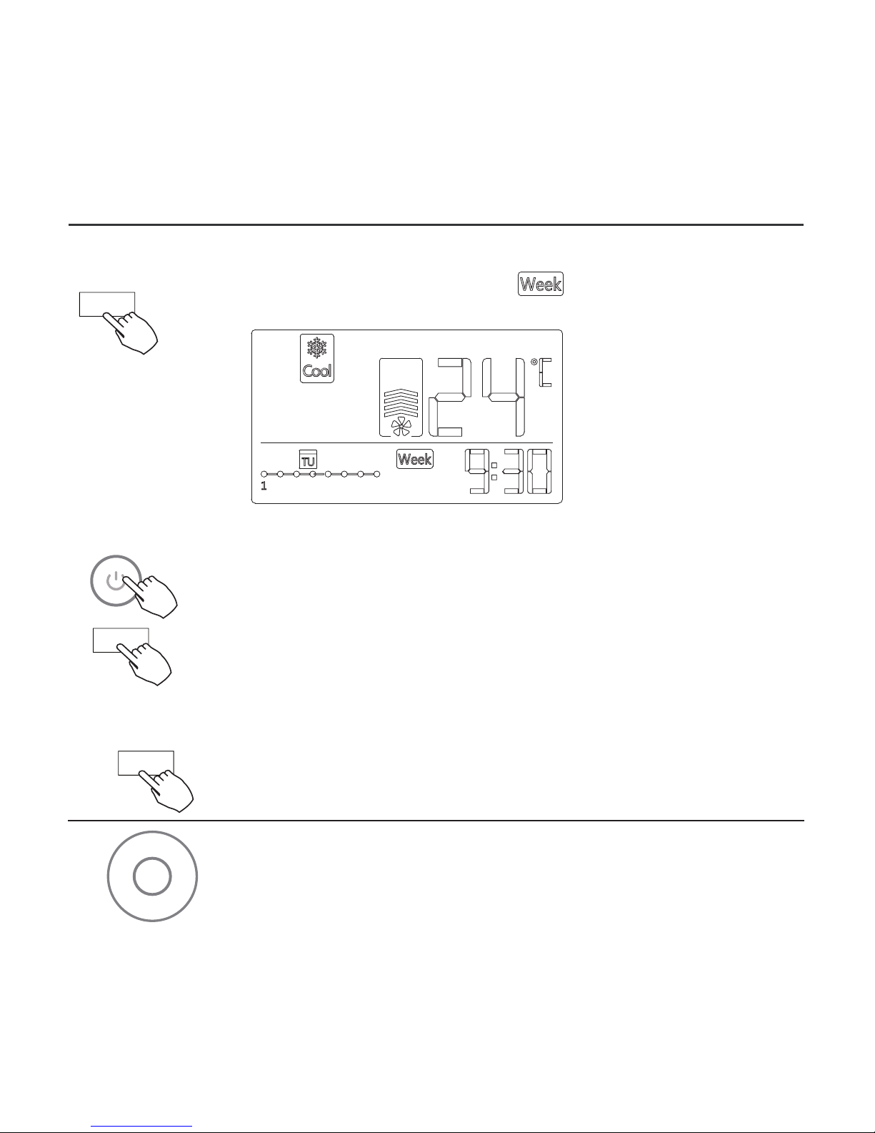
To start
WEEKLY timer operation
Press Timer to select the , and then the timer
starts automatically.
ex.
To cancel
The timer mode can also be canceled by changing the
timer mode using Timer.
Press Power to cancel the timer mode.
To set the DAY OFF (for a holiday)
After setting the weekly timer, press CONFIRM.
1
Press + or − to select the day of the week.
2
Confirm
-
+
Page 38
34
12. WEEKLY TIMER
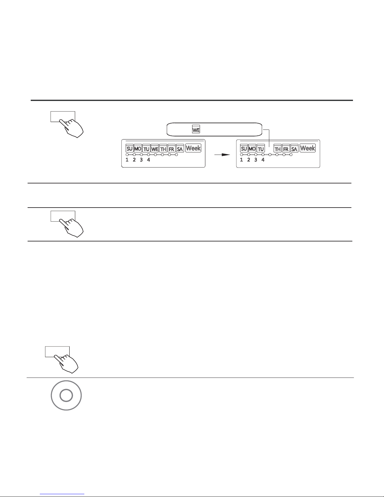
Press BACK to revert to the weekly timer.
Press DAY OFF to create an off day.
3
5
● To cancel, follow the same procedures used for setup.
4
ex.The DAY OFF is set for Wednesday
Set the DAY OFF for other days by repeating the steps
2 and 3.
The mark is hidden
● NOTE: The DAY OFF setting is cancelled automatically after the set
day has passed.
Copy out the setting in one day into the other day.
In the weekly timer, press CONFIRM.
1
2
Press + or − to select the day to copy from.
● A scheduled event, made once, can be copied to another day of the
week. The scheduled events of the selected day of the week will be
copied. The effective use of the copy mode ensures the ease of
reservation making.
Day off/Del
Back/Turbo
Confirm
-
+
Page 39
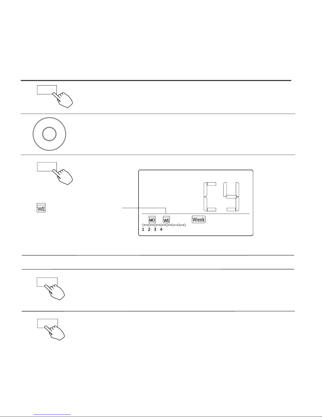
35
12. WEEKLY TIMER
Press COPY, the letters CY appear on the LCD.
3
4
Press + or − to select the day to copy to.
Press CONFIRM to confirm the settings.
Press BACK to revert to the weekly timer.
5
Press COPY to confirm.
Other days can be copied by repeating steps 4 and 5.
ex. Copy the setting of Monday to Wednesday
The mark flashes quickly
6
7
8
Copy/
Follow me
-
+
Copy/
Follow me
Confirm
Back/Turbo
Page 40
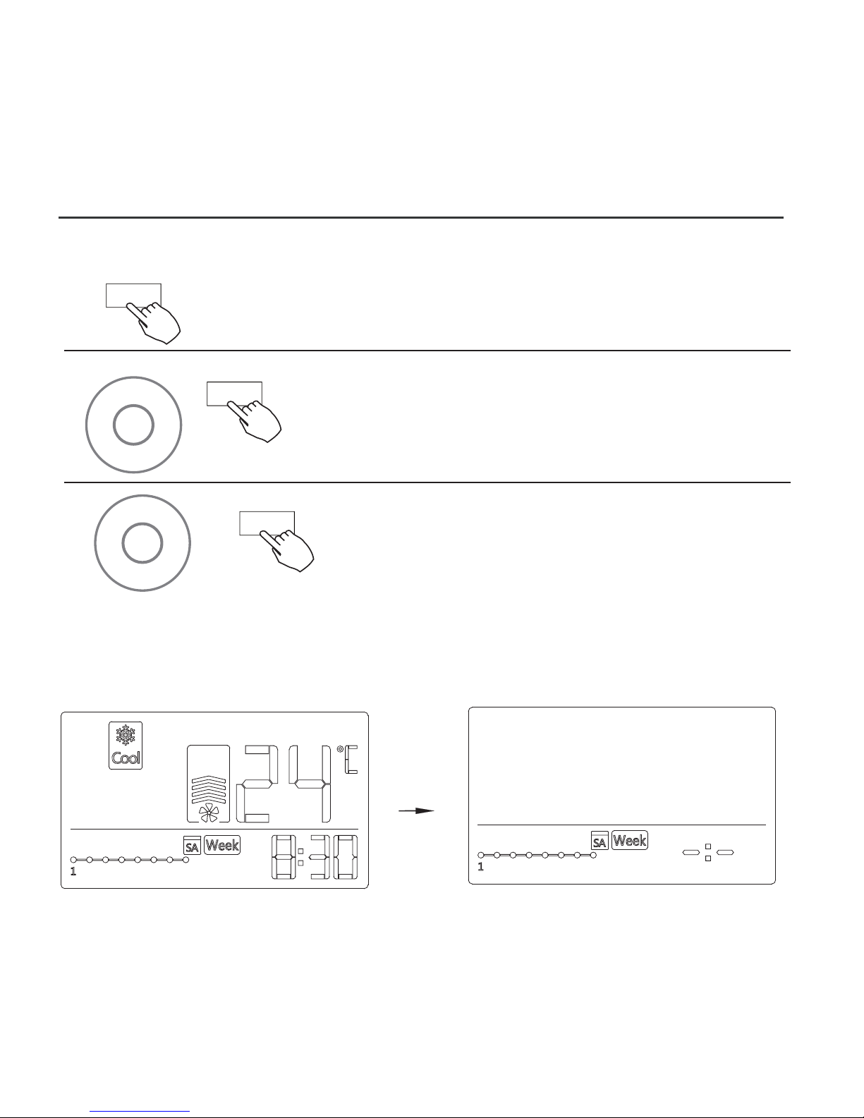
36
12. WEEKLY TIMER
Delete the time scale in one day.
Press + and − to select the setting time want to delete. The setting time,
mode, temperature and fan speed appear on the LCD. The setting time,
mode, temperature and fan speed can be deleted by pressing the DEL
(day off).
During the weekly timer setting,
press CONFIRM.
1
2
Press + and − to select the day of the week
and then press CONFIRM.
3
ex. Delet the time scale 1 in saturday
Confirm
-
+
Confirm
-
+
Day off/Del
Page 41
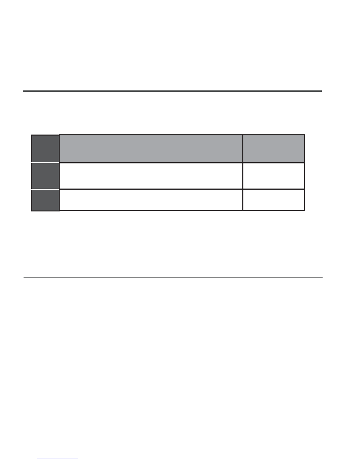
13. FAULT ALARM HANDING
MALFUNCTION AND PROTECTION DEFINITION
DISPLAY
DIGITAL TUBE
F0
F1
NO.
1
2
The faceplate is abnormal
Communication error between wired
controller and indoor unit
If the system does not properly operate except in the aforementioned
cases or the aforementioned malfunctions are evident, investigate the
system according to the following procedures.
Please check the indoor unit’s error display and review the owner’s
manual if other error codes appear.
14.TECHNICAL INDICATION AND REQUIREMENT
EMC and EMI comply with the CE certification requirements.
37
Page 42

QSXUI-009AEN
16117100A02776
The design and specifications are subject to change without prior notice
for product improvement.Consult with the sales agency or manufacturer
for details.
20160312
 Loading...