

Midea JZ*-Q40 SERIES, 75G50*****-G SERIES, JZ*-Q501G SERIES, JZ*-Q44 SERIES, JZ*-Q41 SERIES Service Manual
...Page 1
1
Service Manual
For Built-in gas hob
Model list:
JZx-Q40xxxx, JZx-Q41xxxx,
JZx-Q44xxxx, JZx-Q45xxxx
JZx-Q501Gxx JZx-Q502Gxx
JZx-Q502Sxx 60Qxxxxxxx
60Gxxxxxxx- xxx 70Gxxxxxxx- xxx
75G50xxxxx- Gxx 75G50xxxxx- Sxx
90Gxxxxxxx- Gxx 90Gxxxxxxx- Sxx
Warnings:
This service manual is not available to the general users, but only applies to
professional technicians with relevant qualifications. Any incorrect maintenance
may result in other dangers!
The power and gas supply must be cut off before maintenance!
A new power cord which meets the relevant technical requirements must be used
once possible hidden malfunctions are found with the current power cord (refer to
this Manual)!
Please read carefully all safety warnings in this Manual before maintenance!
The product is prohibited from using until test is conducted as per relevant
regulations after maintenance!
This service manual applies to many models, so the specific operations please prevail in
kind!
V3.0
May, 2015
Page 2

2
Catalogue
1. Precaution ........................................................................................................................ 4
1.1. Safety Precaution ............................................................................................................................................ 4
1.2. Warning ........................................................................................................................................................... 4
2. Description of the appliance ............................................................................................ 5
2.1. Features ........................................................................................................................................................... 5
2.2. Components and parts .................................................................................................................................... 6
3. Installation ....................................................................................................................... 7
3.1. Dimension ........................................................................................................................................................ 7
3.2. Installation Dimension ..................................................................................................................................... 8
4. Electric Diagram ....................................................................................................................................... 9
5. Reassembly and Disassembly ........................................................................................ 10
5.1. Safety precautions ......................................................................................................................................... 11
5.2. Tools .............................................................................................................................................................. 11
5.3 Disassembly .................................................................................................................................................... 12
5.3.1. Disassemble the Top Plate ..................................................................................................................... 12
5.3.2. Disassemble the Thermocouple ............................................................................................................. 13
5.3.3. Disassemble of the Ignition Pin .............................................................................................................. 13
5.3.4. Disassemble of the Microswitch Harness .............................................................................................. 13
5.3.5. Disassemble of the Gas Pipe .................................................................................................................. 14
5.3.6. Disassemble of the Bottom Cup ............................................................................................................. 14
5.3.7. Disassemble of the Power Cord Assembly ............................................................................................. 14
5.3.8. Disassemble of the igniter ...................................................................................................................... 15
5.3.9. Disassemble of the Valve & Manifold Pipe Assembly ............................................................................ 15
5.310. Disasmble of the Gas Connection ......................................................................................................... 16
5.3.11. Disassemble of thebottom plate .......................................................................................................... 16
5.4. Reassembly .................................................................................................................................................... 17
5.4.1. Reassemble of the Ignition Pin ............................................................................................................... 17
5.4.2. Reassemble of the Thermocouple.......................................................................................................... 17
5.4.3. Reassemble of the Gas Pipe……………………………………………………………………………………………………………..17
5.4.4. Check Point after assemble .................................................................................................................... 17
6. Troubleshooting ............................................................................................................. 17
6.1. Troubleshooting ............................................................................................................................................ 18
6.2. Problems and Corrective Measures .............................................................................................................. 19
6.3. Maintenance and test ................................................................................................................................... 21
7. Gas Conversion .............................................................................................................. 22
7.1. Replacement of gas-type fitting .................................................................................................................... 22
Page 3

3
7.2. Replacement of the injector of the burners .................................................................................................. 22
8. Appendix ........................................................................................................................ 24
Technical & quality requirements for Built-in gas hob......................................................................................... 24
Page 4
4
1. Precaution
1.1. Safety Precaution
1. Do not modify this appliance. This appliance should be serviced by an authorized person.
2. All repairs should be done in accordance with the procedures described in this manual.
3. Before you begin, turn off the gas and electricity supply to the appliance. Remove
remaining gas in product completely by igniting burner.
4. Be sure that all of built-in protective devices are replaced. Restore any missing protective
shields.
5. Do not connect the gas and electricity supply before replacement complete.
6. Use replacement components that have the same ratings. A replacement part that does not
have the same safety characteristics as the original might create shock, fire or other
hazards
7. You must conduct a gas leakage test after receiving after-sales service in gas pipe and gas
connector. Never touch any circuit wiring with your hand nor with uninsulated tool during
operation.
1.2. Warning
1. The power cord shall be replaced with the original power cord, specifications for an
insulation power line which is no less than AWG8*2 +AWG10*1 and resists
temperature of greater than 60℃.
2. All apparatus within a radius of 50mm from this product must resist temperature of
greater than 75°C, otherwise, deformations are easily to be caused during the
application process of this product.
3. When the wrapping materials are removed, keep such materials like metal sheet,
packing bag, foam and screws out of reach of children’s reach to avoid potential
dangers. For example, the children may suffocate as a result of swallowing tiny
components or playing with packing bag.
Page 5
5
2. Description of the appliance
2.1. Features
Glass: Q502 GXX
Stainless:Q411 SXX
Page 6
6
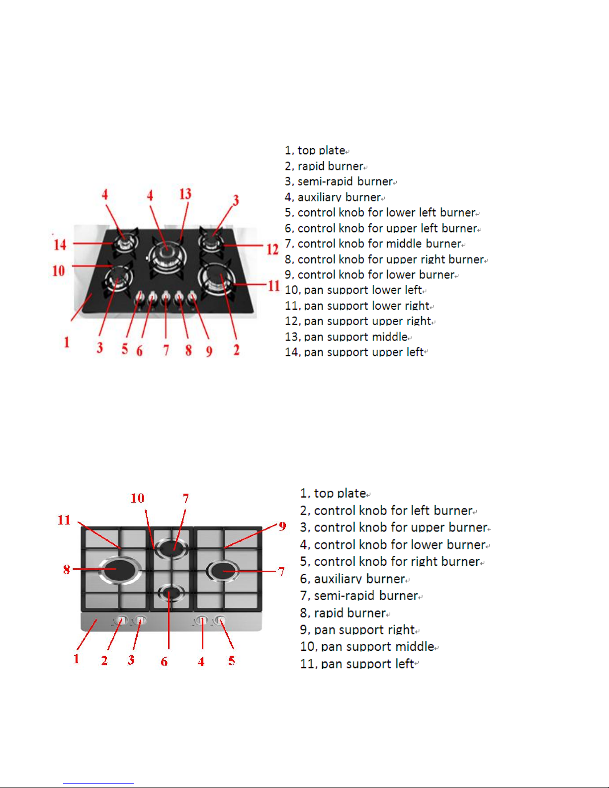
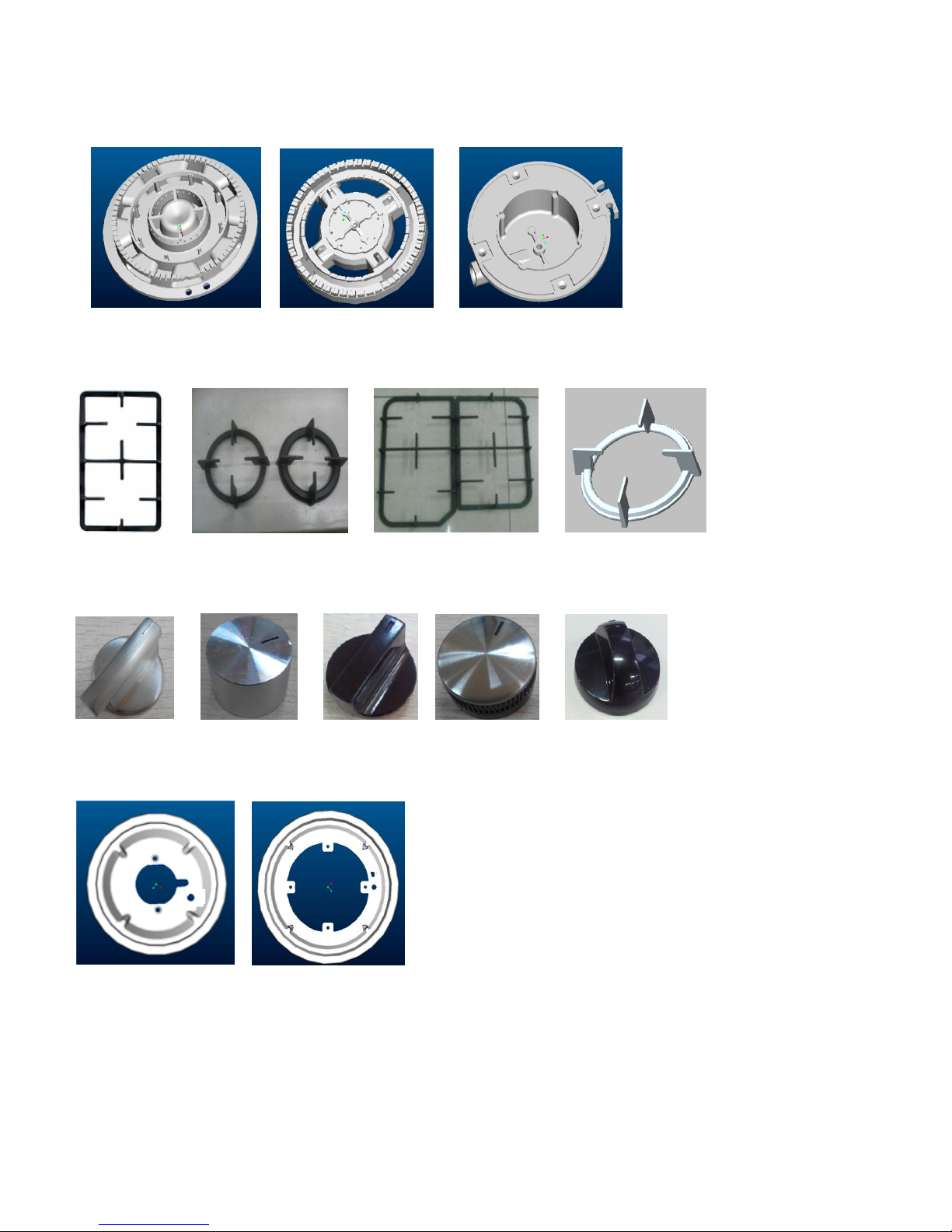
2.2. Components and parts
(1). Burner
(2) .Pan support
(3). Knob
(4) .Drip tray
Page 7
7
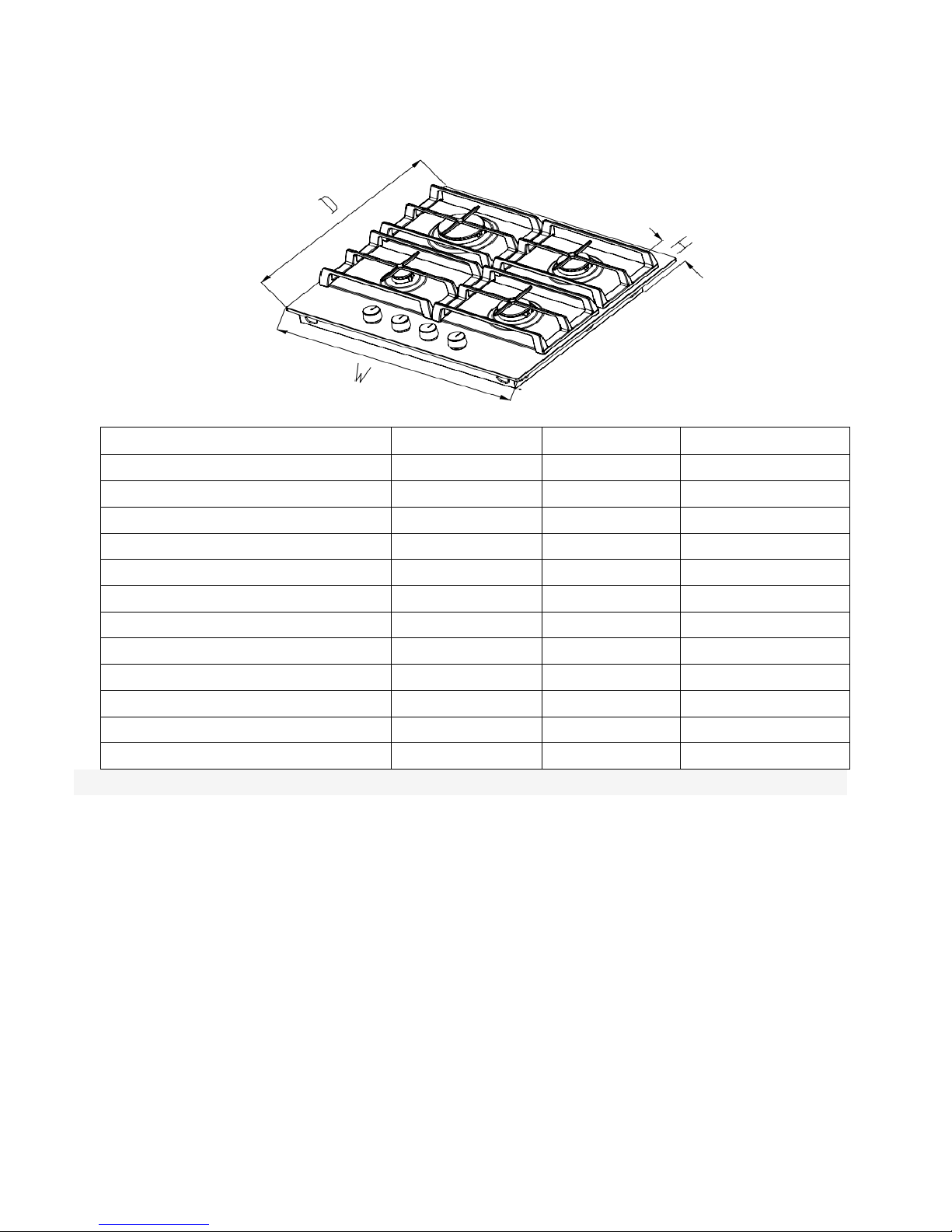
3. Installation
3.1. Dimension
Model
W (mm)
H (mm)
D (mm)
Q40xxxx
590
95
500
Q41xxxx
590
95
500
Q44xxxx
580
95
510
Q45xxxx
600
95
510
Q501Gxx
705
110
460
Q502Gxx
770
110
510
Q502Sxx
760
110
500
60Qxxxxxx
580
86
500
60Gxxxxxxx- xxx
600
110
510
70Gxxxxxxx- xxx
705
110
510
75G50xxxxx- xxx
750
90
510
90Gxxxxxxx- xxx
860
100
520
Note: Dimensions for reference only
Page 8
8
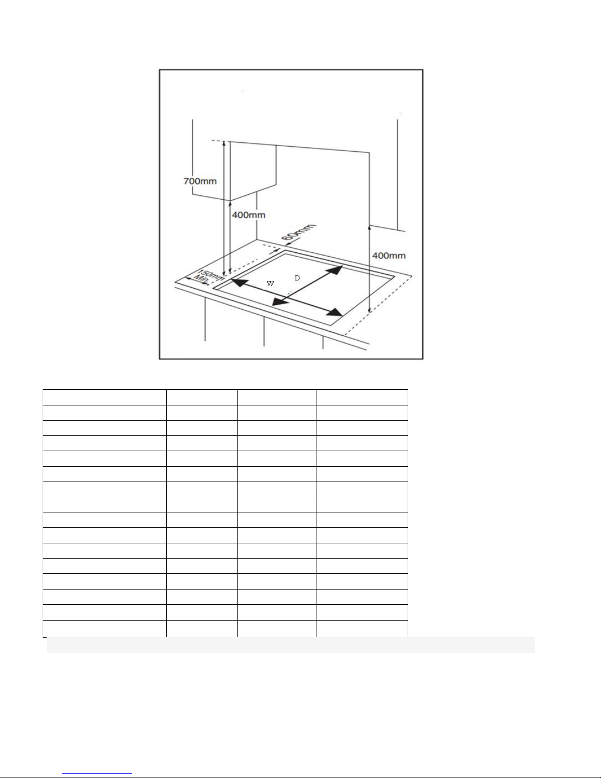
3.2. Installation Dimension
Cut out size:
Model
W(mm)
D (mm)
T(mm)
Q40xxxx
553
473
30(min)
Q41xxxx
553
473
30(min)
Q44xxxx
560
490
30(min)
Q45xxxx
580
490
30(min)
Q501Gxx
667
470
30(min)
Q502Gxx
730
470
30(min)
Q502Sxx
730
470
30(min)
60Qxxxxxxx
560
480
30(min)
60Gxxxx08x- xxx
553
473
30(min)
60Gxxxx4xx- xxx
553
473
30(min)
60Gxxxx006- xxx
580
490
30(min)
60Gxxxxxxx- xxx
560
490
30(min)
70Gxxxxxxx- xxx
560
490
30(min)
75G50xxxxx- xxx
730
490
30(min)
90Gxxxxxxx- xxx
850
490
30(min)
Note: Dimensions for reference only
Page 9

9
This appliance is to be built into a kitchen unit or worktop of right size, providing the following minimum
distances are allowed;
– The edge of the appliance must be a minimum distance of 55mm from a rear wall.
– A minimum distance of 150mm must be left between the side edges of the appliance and any adjacent
cabinets or walls.
– The minimum distance combustible material can be fitted above the appliance in line with the ed ges
of the appliance is 400mm.
– The minimum distance combustible material can be fitted directly above the appliance is 700mm.
–This panel (a) must be positioned at a maximum distance of 150mm below the worktop.
Gas pipe or connector shouldn't be bent or blocked by any other appliances
– You must conduct a gas leakage test after installation over gas connection and gas pipe.
– An oven must have forced ventilation to install a hob above it.
– Check the dimensions of the oven in the installation manual.
– The cut out size must obey the indication.
Page 10

10
4. Electric Diagram
a. Four burners model
b. Five burners model
Page 11

11
5. Reassembly and Disassembly
5.1. Safety precautions
5.2. Tools
Most of the tools that you might need are shown below. Some are optional.
WARNING
Turn off power for safety and appliance protection.
Close middle valve to prevent gas leakage
Keep away from inflammable materials around appliance.
Before work, put on gloves.
CAUTION
Cool off the appliance for a while right after using appliance for your safety because you can get
burners by high temperature from the appliances.
Page 12

12
5.3 Disassembly
5.3.1. Disassemble the Top Plate
Step 1: Remove parts on the Top Plate
a. Remove parts on the top plate: Burner lids, Flame spreaders, Control handles
b. When disassembling, keep parts safe, do not drop them to the appliance.
Step 2: Disassemble of Screws on the Top Plate
a. Remove the screws of the burner
b. In some versions, remove screws on the side of bottom plate.
c. Be careful in order not to damage screw heads when disassembling.
d. Be careful not to damage the top plate.
Step 3:Detachment of the Top Plate
a. Separate the top plate.(In case of stainless steel model, take off the sponge.)
b. During assembly, be careful in order not to give physical impact on parts such as ignition devices,
flame supervision devises..
Page 13

13
5.3.2. Disassemble the Thermocouple
Step 1: Unscrew the nut out.
Step 2: Pull the silver terminal of Thermocouple
Step 3: When reassembling, replace parts correctly
5.3.3. Disassemble of the Ignition Pin
Step 1: Pull the washer and take off ignition pin
Step 2: Pull the housing of Ignition pin out of the igniter.
Step 3: When reassembling, replace parts correctly.
5.3.4. Disassemble of the Microswitch Harness
Step 1: Before you disassemble the harness, take off the plastic e – ring.
Step 2: When you take off the micro switch harness , please be careful not to break the hook.
Step 3: When you reassemble the harness, replace it correctly.
Step 4: Detach the wire from the power cord assembly harness.
Step 5: Hold housing of the wire by hand and pull it out of the igniter
.
Page 14

14
5.3.5. Disassemble of the Gas Pipe
Step 1: Unscrew the nuts out. at both ends of the pipes
Step 2: Pull the pipes
5.3.6. Disassemble of the Bottom Cup
Step 1: Remove all screws on the bottom cup
Step 2: Detach the bottom cup from the base box burner
5.3.7. Disassemble of the Power Cord Assembly
Step 1 . Detach the wire from the Microswitch Harness.
Step 2 . Hold housing of the wire by hand and pull it out of the igniter.
Step 3. For power cord grounding, you must use grounding screw attached with washer.
Step 4 . Remove 2 screws and detach the power cord ass’y set
Page 15

15
5.3.8. Disassemble of the igniter
Step1. Remove 2 screws
Step2. Detach the igniter from the base box burner.
5.3.9. Disassemble of the Valve & Manifold Pipe Assembly
Step 1. Remove 5 screws
Step 2. Remove the screw to take off pipe assy.
Step 3. Remove 2 screws and detach the valve from the manifold pipe assembly
Step 4. You must check the gasket when you disassemble or assemble.
Step 5. If you have faulty one, replace it with new one.
Step 6. Conduct a leakage test after reassembling.
screws
Page 16

16
5.3.10. Disasmble of the Gas Connection
Step 1. When you disassemble/assemble gas connection, use 2 spanners. One for fixing gas connection
elbow, the other for tightening gas hose.
Step 2. Tighten enough to prevent gas leakage.
Step 3. Once you’re done, conduct leakage test
5.3.11. Disassemble of the bottom plate
Step 1. Separate casing on sink.
Step 2. Detach the appliance as checking the status of the gas connection and the power cord assembly set.
Page 17

17
5.4. Reassembly
5.4.1. Reassemble of the Ignition Pin
Step 1. Pull the line of the ignition pin in to the hole on bottom cup along the gap on bottom cup
Step 2. Push ignition pin to adjust the position
Step 3. Klemm ignition pin with snap spring to fox the ignition pin.
5.4.2. Reassemble of the Thermocouple
Step 1. Insert thermocouple into the the relevant hole of the bottom cup from bottom to top.
Step 2. Adjust position of the thermocouple in the hole of the bottom cup.
Step 3. screw up the nut to fix the thermocouple.
5.4.3. Reassemble of the Gas Pipe
Step 1.Insert the head of the gas pipe into installation parts of the bottom cup or the valve
Step 2.Screw up the nut of the joint with spanner
5.4.4. Check Point after assembly
a. At completion of the appliance repair, assemble after removing tools inside of the appliance.
b. You must conduct a leakage test after repairing.(refer to the leakage test on 5.3)
c. If ignition does not work, repeat ignition several times so that you
can remove remaining air in the gas connection
d. Check combustion status by conducting aging
Page 18

18
6. Troubleshooting
6.1. Troubleshooting
Page 19

19
6.2. Problems and Corrective Measures
Page 20

20
Note!
1 Check the ground wire before the fault is detected;
2 Enough attention must be given to high voltage circuit.
Page 21

21
6.3. Maintenance and test
Air leakage test
Tool: Air leakage device, soapy water
1. Professional repair procedures
a) Connect product to the air leakage device and set the test pressure at 15kPa;
b) The plug valve shall be kept closed and the gas pipelines may be tested its leakage through air leakage
device;
c) All plug valves shall be kept open, block the injectors at the burner, the flame-out protection valve shall
be kept open and the gas pipelines may be tested their leakage through air leakage device.
The maximum leakage must be controlled below 0.5mL/min as required in the test.
2. Simple procedures:
a) Connect the product to the gas source being used;
b) Smear soapy water at each joint of the product gas pipelines, the plug valve is kept closed, check
visually each joint for air bubbles;
c) Smear soapy water at each joint of product gas pipelines, all plug valves shall be kept open, block the
injectors at the burner, the flame-out protection device valve shall be kept open and check visually for any air
bubbles.
No air bubbles shall be detected at each joint as required in the test.
Note: Any component of the product gas pipelines shall not be disassembled or replaced only if the air
leakage is proved in conformity with relevant requirements.
Page 22

22
7. Gas Conversion
All work must be carried out by a qualified technician,
Before you begin, turn off the gas and electricity supply to the appliance.
7.1. Replacement of gas-type fitting
Tool: Open-end wrench
Steps for operation:
a) Disassemble with a wrench the gas-type fittings from main gas tube.
b) Lock tightly a replaceable gas-type fitting onto the main gas tube.
7.2. Replacement of the injector of the burners
Tool: 7mm box spanner
Steps for operation:
Step 1: Remove the pan support,,burner lid and flame spreader.
Step 2: Unscrew the injector with a 7 mm box spanner and replace it with the stipulated injector for new
gas supply.(see the following table)
Step 3: Carefully reassemble all the components.
After injectors are replaced ,it is advisable to tighten the injector in place. strongly.
injector
Joint
Seal washer
Gas tube
Page 23

23
注:
Comparison list for injector replacement
Nominal heat input and rates see below at 15℃ at 1013mbar
Page 24

24
8. Appendix
Technical & quality requirements for Built-in gas hob
a) Use of natural gas burner when the burner works 10 minutes in rated power,turn it to little fire
and keep 60 seconds,reduce the gas pressure to 1400pa,the fire shouldn’t extinct.
b) Neither flame off nor back burning should appear when the flame is in the fire hole of burner.
c) There should be no cracks and graze in the glass components and china components, besides the
fringe of them.
d) In Rated gas\rated gas pressure,ignite the burner,test the time from ignition to burner working
stably,it should not be more than 5 seconds.
e) In Rated gas\rated gas pressure,after the burner working for 15 minutes,turn off the plug valve,
then test the time during turning off plug valve and flame-out protection device shutting down,it
should be less than 90 seconds.
f) Every burner should be test ignition ,fuse transferring time\ flame stabilization,ignition\ fuse
transferring time should be less than 5 seconds. Flame-out will be allowed in 5 seconds after
ignition,but flame should be stable in 1 minute.
g) If it may cause security problems after corrosion, electric current and other mental parts should be
corrosion resistance under the normal conditions of use. Live parts and heat insulator should be
prevented to contact with each other unless the heat insulator is corrosion resistance ,
non-hygroscopic and flame-retardant.
h) The shaft of Knob, handle ,control stick and other similar parts should be electrically neutral unless
the shaft is out of the reach when the other parts are taken down.
i) The clamp device of ground terminal should be tight enough to avoid accidental loosening. The wire
length from power cord block terminal or cord fixing device to block terminal should be
appropriate .If the flexible cord slips off from the cord block terminal, current carrying conductor
should tighten firstly compared with earth conductor.
j) Phenomenon that may reflect cooking appliance performance should not appear of the pan support
in normal use.
k) Gas tightness should be accord with standard request after the gas connection was disassembled five
times.
 Loading...