

Page 1
IC INVERTER SERIES
Service Manual 2012
ICSI-A-1205
Page 2

CONTENTS
1. Precaution .................................................................................................................................................... 3
1.1 Safety Precaution .......................................................................................................................... 3
1.2 Warning ......................................................................................................................................... 3
2. Function ........................................................................................................................................................ 7
3. Dimension .................................................................................................................................................... 8
3.1 Indoor Unit ..................................................................................................................................... 8
3.2 Outdoor Unit .................................................................................................................................. 9
4. Refrigerant Cycle Diagram ........................................................................................................................ 11
5. Wiring Diagram .......................................................................................................................................... 12
5.1 Indoor Unit ................................................................................................................................... 12
5.2 Outdoor Unit ................................................................................................................................ 13
6 Installation Details ...................................................................................................................................... 14
6.1 Wrench torque sheet for installation ........................................................................................... 14
6.2 Connecting the cables ................................................................................................................ 14
6.3 Pipe length and the elevat ion ..................................................................................................... 15
6.4 Installation for the fir st time ......................................................................................................... 16
6.5 Adding the refrigerant after running t he s ystem for many years ................................................ 19
6.6 Re-installation w hi le t he indoor unit need to be repaired ........................................................... 20
6.7 Re-installation w hi le t he outdoor unit need to be repaired ......................................................... 22
7. Operation Characteristics ......................................................................................................................... 25
8. Electronic function .................................................................................................................................... 26
8.1 Abbreviation ................................................................................................................................ 26
8.2 Display function ........................................................................................................................... 26
8.3 Main Protection ........................................................................................................................... 27
8.4 Operation Modes and Functions ................................................................................................. 28
9. Troubleshooting ......................................................................................................................................... 42
9.1 Indoor Unit Error Display ............................................................................................................. 42
9.2 Diagnosis and Solution ............................................................................................................... 43
Page 3

3
1. Precaution
1.1 Safety Precaution
To prevent injury t o t he us er or other people and property damage, the following instructions
must be followed.
Incorrect operation due to ignoring inst ruction will cause harm or damage.
Before service the unit, be sur e to r ead this service manual at first.
1.2 Warning
Installation
Do not use a defective or under rat ed circuit breaker. Use this appliance on a dedicat ed circuit.
There is risk of fire or electric shock.
For electrical work, contact the dealer, seller, a qualified electrician, or an authorized service
center.
Do not disassemble or repair the product, there is risk of fire or electr ic shock.
Always ground t he product.
There is risk of fire or electric shock.
Install the panel and the cover of control b ox securely.
There is risk of fire of electric shock.
Always instal l a dedicated circuit and breaker.
Improper wiring or installation may cause fore or electric shock.
Use the correctly rat ed breaker of f use.
There is risk of fire or electric shock.
Do not modify or extend the power cable.
There is risk of fire or electric shock.
Do not inst all, remove, or reinstall the unit by yourself (customer).
There is risk of fire, electric shock, explosion, or injury.
Be caution when unpacking and installing the p roduct.
Sharp edges could cause injur y, be especially careful of the case edges and t he f ins on the condenser
and evaporator.
Page 4

4
For installation, always contact the dealer or an authorized service center.
Do not inst all the product on a def ective installation stand.
Be sure the install ation area does not deteriorate with a ge.
If the base collapses, the air conditioner could fall with it, causing pr operty damage, product failure, and
personal injury.
Do not let the air conditioner run for a lo ng time when the humidi ty is very high and a door or a
window is left open.
Take care to ensure that power cable could not be pulled out or damaged during operat ion.
There is risk of fire or electric shock.
Do not place any t hing on the power cable.
There is risk of fire or electric shock.
Do not plug or unplug the power supply plug during operation.
There is risk of fire or electric shock.
Do not touch (operation) the product with wet hands.
Do not place a heater or other appliance near the power cable.
There is risk of fire and electr ic shock.
Do not allow water to run into electrical parts.
It may cause fire, failure of the product, or electric shock.
Do not store or use flammable gas or combustible near the pro duc t .
There is risk of fire or failure of product.
Do not use the pro duc t in a tightly closed space for a long time.
Oxygen deficiency could occur.
When flammable gas leaks, turn off t he gas and open a windo w for ventilation before turn the
product on.
If strange sound s or smoke comes from product, turn the breaker off or disconnect the power
supply cable.
There is risk of electric shock or fire.
Stop operation and close the window in storm or hurricane. If possible, remove the product from
the window before the hurricane arrives.
There is risk of property damage, failure of product, or electric shoc k.
Do not open the inl et gr ill of the product during operation. (Do n ot touch the electrost atic filter, if
Page 5

5
the unit is so equi pped.)
There is risk of physical injury, electric shock, or product failure.
When the product is soaked, contact an authorized service center.
There is risk of fire or electric shock.
Be caution that water could not enter the product.
There is risk of fire, electric shock, or product damage.
Ventilate the product from time to time when operating it t ogether with a stove etc.
There is risk of fire or electric shock.
Turn the main power off when cleaning or maintaining the product.
There is risk of electric shock.
When the product is not be used for a long ti me, disco nnect t he powe r suppl y plug or turn off t he
breaker.
There is risk of product damage or failure, or unintended operation.
Take care to ensure that nob ody could step on or fall onto the outdoor unit.
This could result in person al in jury and product damage.
CAUTION
Always check for gas (refri gerant) leakage after installation or repair of product.
Low refrigerant levels may cause failure of product.
Install the drain h ose t o ensure that water is drained away pr op er l y.
A bad connection may cause water leakage.
Keep level even when installing the product.
It can avoid vibration of wat er lea kage.
Do not inst all the product where t he noise or hot air fr om the outdoor uni t could damage the
neighborhoods.
It may cause a problem for your neighbors.
Use two or more people to lift and t r ansport the product.
Do not install the product where it will be exposed to se a wind (salt spray) directly.
It may cause corrosion on the product. Corrosion, particularly on the condenser and evaporator fins,
could cause product malfunction or inefficient operati on.
Page 6

6
Operational
Do not expose th e sk i n directly to cool air f or long time. (Do not sit in the draft).
Do not use the product for speci al purposes, such as preserving foo ds, wor ks of ar t etc. It is a
consumer air conditioner, not a precision refrigerant system.
There is risk of damage or loss of property.
Do not block the i nl e t or outlet of air flow.
Use a soft cloth to clean. Do not use harsh detergents, solvents, etc.
There is risk of fire, electric shock, or damage to the plastic part s of the product.
Do not touch the metal parts of the product when removing the air filter. They are very sharp.
Do not step on or put anything on the prod uc t . (outdoor units)
Always insert the filt er securely. Clean the filter every two weeks or more often if necessary.
A dirty filter redu ces th e efficiency of the air conditio ner and could c aus e prod uct m alfu nction or da mag e.
Do not insert hands or other objects through air inlet or outl e t while the product is operated.
Do not drink the water drained from the product.
Use a firm stool or ladder when cleanin g or m a i ntaining the pr oduct.
Be careful and avoid pers onal injury.
Replace the all batteries in the remote control with new ones of t he same type. Do not mix old
and new batteries or different types of batteries.
There is risk of fire or explosion.
Do not recharge or disassemble the batteries. Do not dispose of batt er i es in a fire.
They may burn of explode.
If the liquid from t he batt eri es get s o nto y our ski n or cl othes, wa sh it well with c lean water. Do not
use the remote of the batt er i es have leaked.
Page 7

7
2. Function
Model Names of Indoor/Outdoor Units
DC
Inverter
Capacity Indoor units Outdoor units
9k MSIC-09HRDN1-QC2 MOR-09HDN1-QC2
12k MSIC-12HRDN1-QC2 MOR-12HDN1-QC2
Concealed display
Super slim
Easily removable filter
Golden fin
Dry and self clean
Compressor Crankcase Heater(O)
Self-diag. function
Vitamin C filter(O)
Valve protection cover
Horizontal &Vertical swing function
Variable fan speeds
High density silver ion filter
Intelligent sleep mode
I mode
Bio filter(O)
Low ambient cooling(O)
O: optional function
Page 8
8
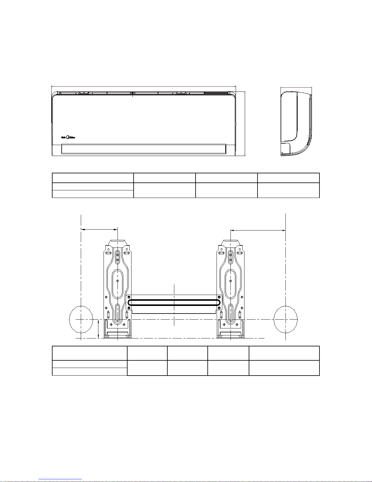
3. Dimension
3.1 Indoor Unit
D
H
W
L
R
H
Model
W H D
MSIC-09HRDN1-QC2
890 310 150
MSIC-12HRDN1-QC2
Model L R
H(mm)
Dimension of
installation hole(mm)
MSIC-09HRDN1-QC2
184 143
45 Φ65
MSIC-12HRDN1-QC2
Page 9
9
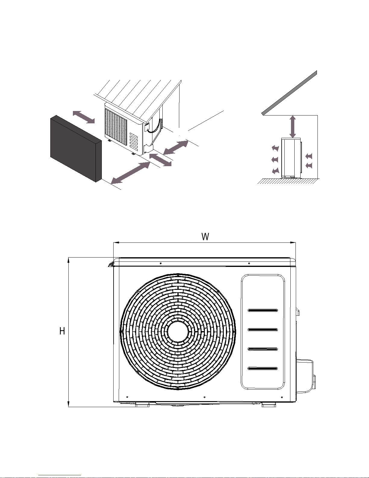
3.2 Outdoor Unit
More than 30cm
More than 60cm
More than 70cm
More than 30cm
More than 60cm
(Service space)
Fence or
obstacles
Page 10
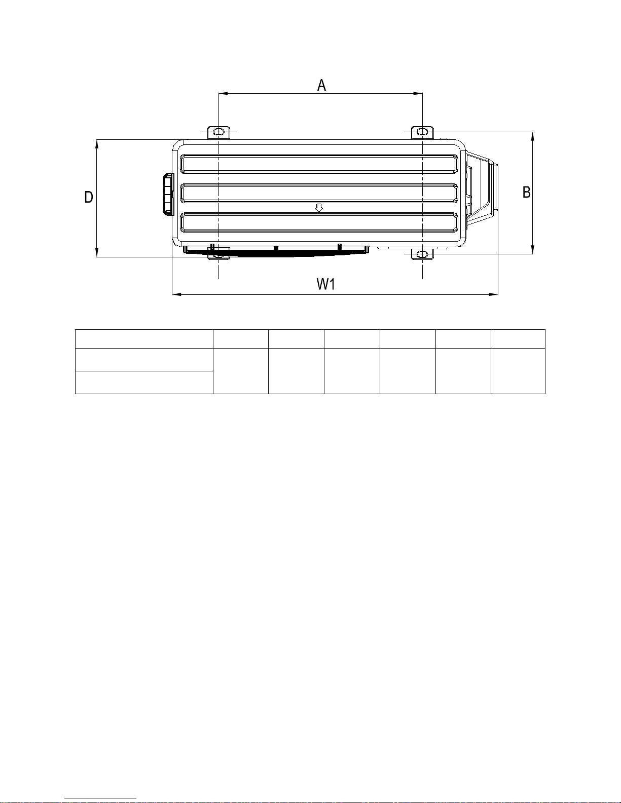
10
Model W D H W1 A B
MOR-09HDN1-QC2
660 265 540 732 458 276
MOR-12HDN1-QC2
Page 11
11
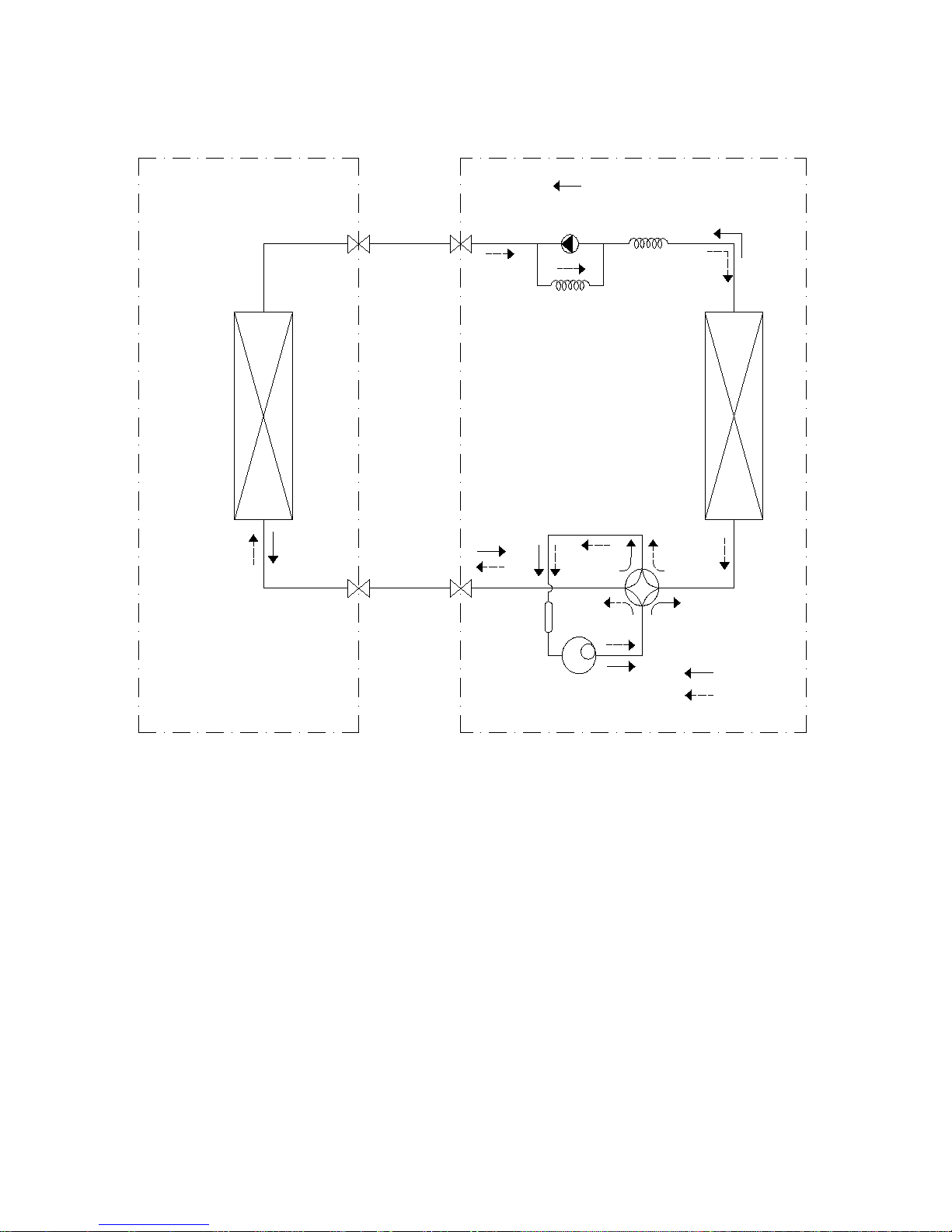
4. Refrigerant Cycle Diagram
INDOOR OUTDOOR
LIQUID SIDE
GAS SIDE
HEAT
EXCHANGE
(EVAPORATOR)
HEAT
EXCHANGE
(CONDENSER)
COMPRESSOR
2-WAY VALVE
3-WAY VALVE
CHECK VALVE
(Heating Model only)
CAPILIARY TUBE
REVERSING VALVE
(Heating Model only)
COOLING
HEATING
ACCUMULATOR
Page 12
12
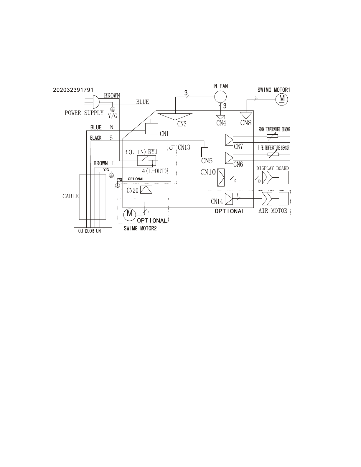
5. Wiring Diagram
5.1 Indoor Unit
MSIC-09HRDN1-QC2, MSIC-12HRDN1-QC2
Page 13
13
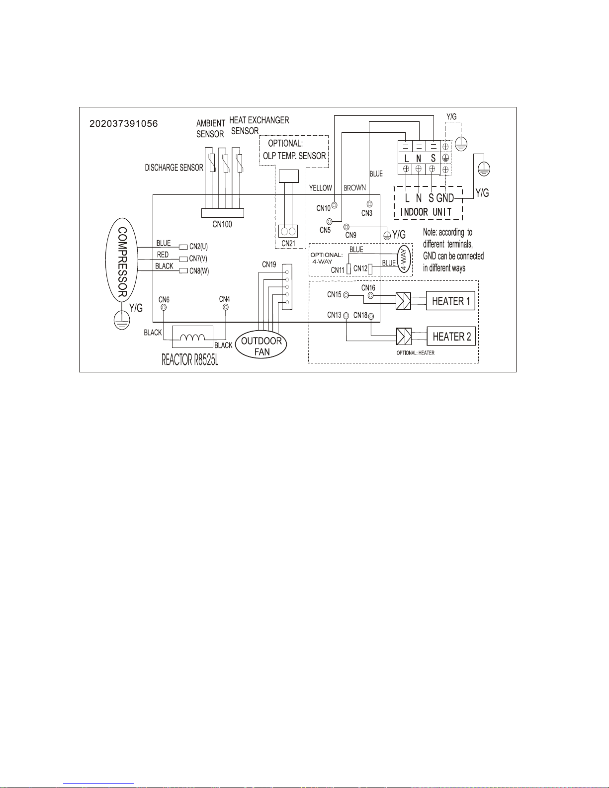
5.2 Outdoor Unit
MOR-09HDN1-QC2, MOR-12HDN1-QC2
Page 14
14
6 Installation Details
6.1 Wrench torque sheet for installation
Outside diameter Torque Additional tightening torque
mm inch N.cm N.cm
Ф6.35 1/4 1500(153kgf.cm) 1600(163kgf.cm)
Ф9.52 3/8 2500(255kgf.cm) 2600(265kgf.cm)
Ф12.7 1/2 3500(357kgf.cm) 3600(367kgf.cm)
Ф15.9 5/8 4500(459kgf.cm) 4700(479kgf.cm)
Ф19 3/4 6500(663kgf.cm) 6700(683kgf.cm)
6.2 Connecting the cables
The power cord of connect should be selected according to the following s pecifications sheet.
Rated current of appliance
Nominal cross-sectional area (mm²)
>3 and ≤6
0.75
>6 and ≤10
1
>10 and ≤16
1.5
>16 and ≤25
2.5
The cable size and the current of the fuse or switch are determined by the maximum current indicated
on the nameplate which located on the side panel of the unit. Please refer to the nameplate before
selecting the cable, fuse and sw it ch.
Page 15

15
6.3 Pipe length and the elevation
The pipe length and refrigerant amount:
Model
Pipe si ze
Standard
length
(m)
Max.
Elevation
B (m)
Max.
Length
A (m)
Additional
refrigerant
(g/m)
Gas Liquid
MSIC-09HRDN1-QC2+MOR-09HDN1-QC2
3/8’’
(Ф9.52)
1/4’’
(Ф6.35)
5 8 20 20
MSIC-12HRDN1-QC2+MOR-12HDN1-QC2
Caution:
The capacity test is based on the standard length an d the maximum permissive length is based on the
system reliability.
The oil trap should be inst all ed per 5-7 meters.
Page 16
16
6.4 Installation for the first time
Air and moisture in the refrigerant system have undesirable effects as below:
● Pressure in the system rises.
● Operating current rises.
● Cooling or heating efficiency drops.
● Moisture in the refrigerant circuit may freeze and block capillary tubing.
● Water may lead to corrosi on of parts in the refrigerant sys t em.
Therefore, the indoor units and the pipes between indoor and outdoor units must be leak tested
and evacuated to remove gas an d m oisture from the system.
Gas leak check (Soap water method):
Apply soap water or a liquid neutral detergent on the indoor unit connections or outdoor unit
connections by a soft brush to check for leakage of the connecting points of the piping. If bubbles
come out, the pipes have leakage.
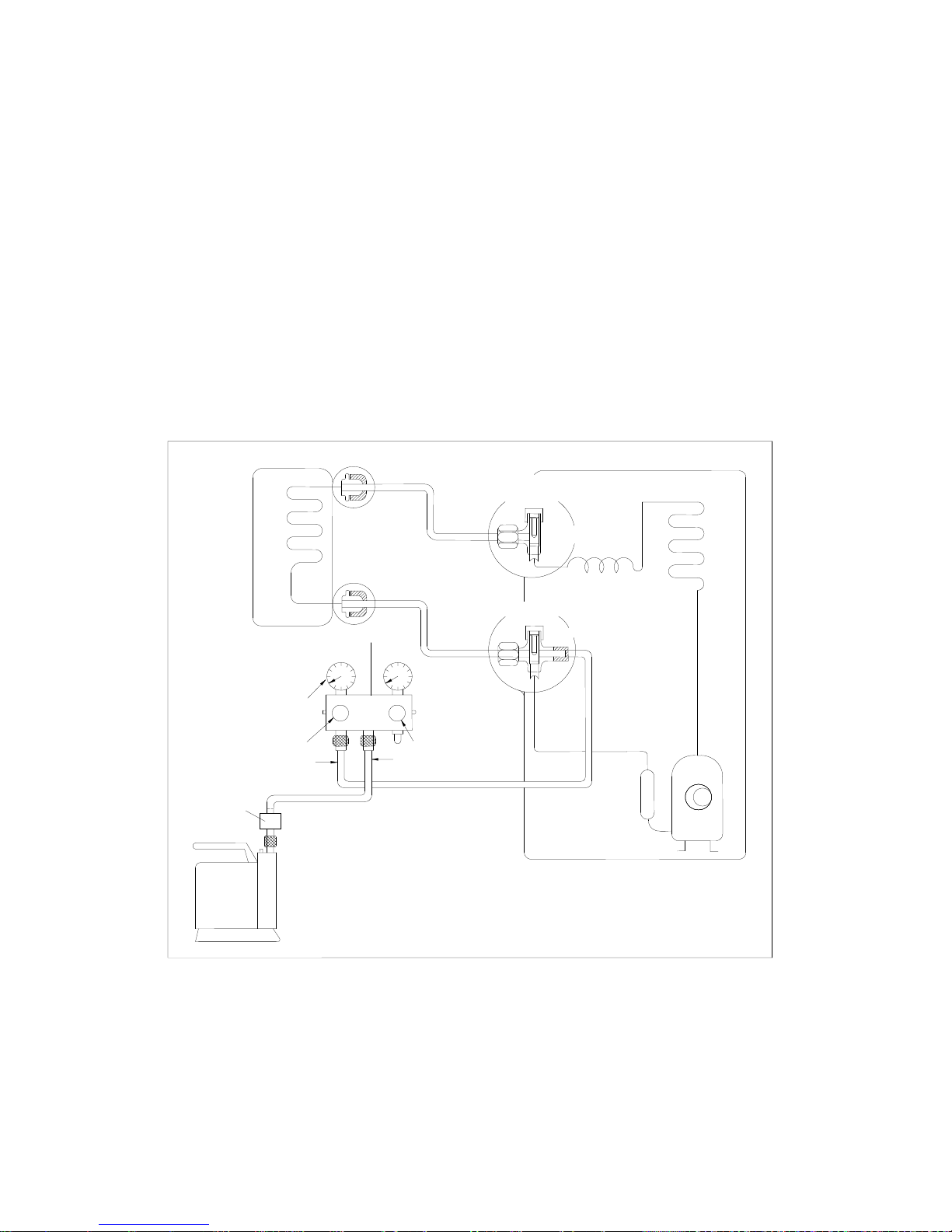
1. Air purging with vacuum p um p
1) Completely tighten the flare nuts of the indoor and outdoor units, confirm that both the 2-way and
3-way valves are set to the closed position.
2) Connect the charge hose w it h t he push pin of handle lo to the 3-way valves gas service port..
3) Connect the charge hose of ha ndle hi connection to the vacuum pump.
4) Fully open the handle Lo of the ma ni fold valve.
5) Operate the vacuum pum p t o evacuate.
6) Make evacuation for 30 minutes and check whether the compound meter indicates -0.1Mpa. If
(Indoor unit)
(Liquid side)
(Gas side)
Vacuum
pump
Vacuum
pump
Lo
Hi
Handle Hi
Two-way valve
Close
Manifold valve
Compound meter
Pressure
gauge
-
0.1M
Pa
Handle Lo
Charge hose
Charge hose
(Outdoor unit)
Close
Three
-way valve
Page 17
17
the meter does not indicate -0.1Mpa after pum ping 30 minutes, it should be pump ed 20 minutes more. If
the pressure can’t achi eve -0.1Mpa after pum ping 50 minutes, please check if there are some leakage
points.
Fully close the handle Lo valve of the manifold valve and stop the operation of the vacuum pump.
Confirm that the gauge needle does not move (approximately 5 minutes after turning off the vacuum
pump).
7) Turn the flare nut of the 3-way valves about 45° counterclo ckwise for 6 or 7seconds after the g as
coming out, then tighten the flare nut again. Ma ke sure the pressur e display in the pressure in dicator is
a little higher than the atmosph er e pr essure. Then remove the c har ge hose from the 3 way valve.
8) Fully open the 2 way valve and 3 way valve and securely tighten the cap of the 3 way valve.
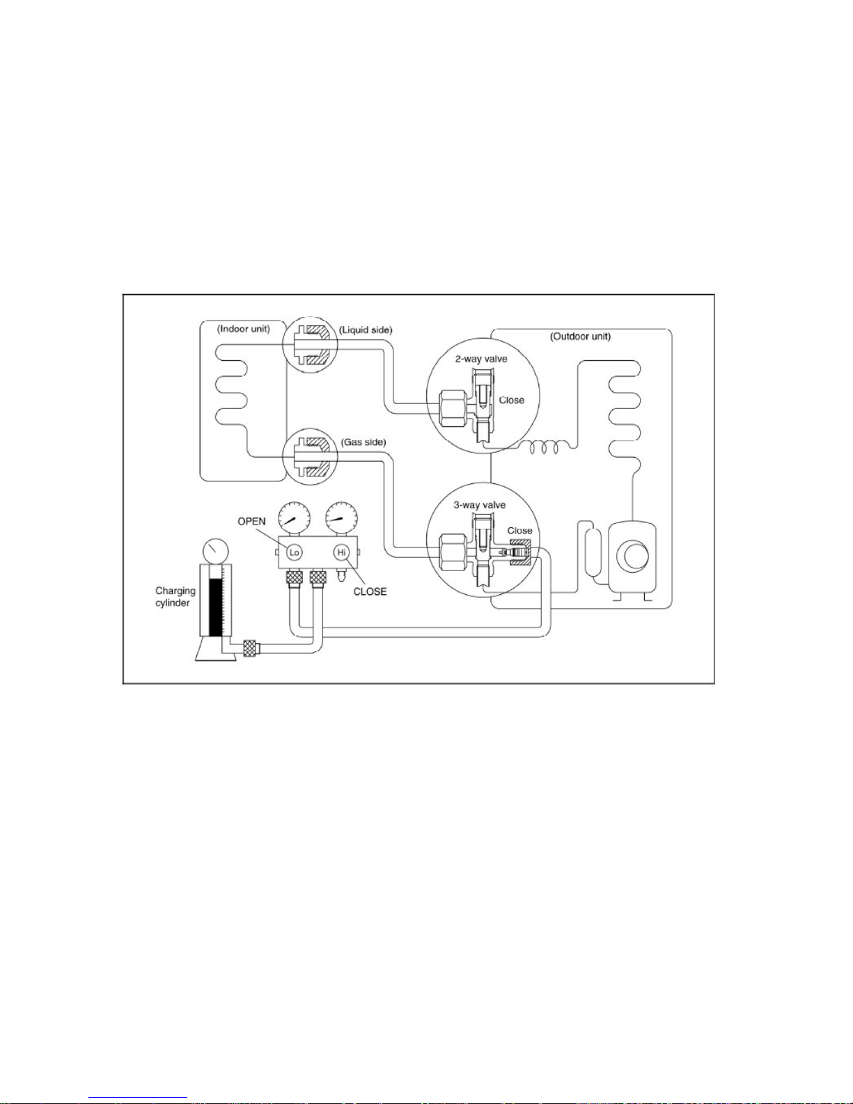
2. Air purgi ng by refrigerant
Procedure:
1). Confirm that both the 2-way and 3-way valves are set to the closed positi on.
2). Connect the charge set and a char ging cylinder to the service port of the 3-way valve.
3). Air purging.
Open the valves on the charging cylinder and the charge set. Purge the air by loosening the flare nut on
the 2-way valve approximately 45’ for 3 seconds the n closing it for 1 minute; repeat 3 times.
After purging the air, use a torque wrench to tig ht en the flare nut on the 2-way valve.
4). Check the gas leakage.
Check the flare connections for gas leakage.
5). Discharge the refrigerant.
Page 18

18
Close the valve on the charging cylinder and discharge the refrigerant by loosening the flare nut on the
2-way valve approximatel y 45’ until the gauge indicates 0.3 to 0.5 Mpa.
6). Disconnect the charg e set and th e char gi ng cyli nder, and set the 2-way and 3-way valves to t he ope n
position.
Be sure to use a hexagonal wrench to operate the valve stems.
7). Mount the valve stems nuts and the service port cap.
Be sure to use a torque wrench to t ighten the service port cap to a torque 18N ·m.
Be sure to check the gas leakage.
3. Adding the refrigerant if the pipe length >5m
Procedure:
1). Connect the charge hose to t he char ging cylinder, open the 2-way valve and the 3-way valve.
Connect the charge hose w hich y ou disco nnecte d fr om the v acuu m pu mp to the v alve at the bot tom of
the cylinder. If the refrigerant is R410A, make the cylinder bottom up to ensure the liquid charge.
2). Purge the air from the charge h ose.
Open the valve at the bottom of the cylinder and press the check valve on the charge set to purge the
air (be careful of the liquid refrigerant).
3) Put the charging cylinder onto the electronic scale and record t he weight.
4) Operate the air conditioner at t he c ool ing mode.
5) Open the valves (Low side) on the charge set and charge the system with l i qui d r efrigerant.
Electronic scale
Page 19

19
6).When the electronic scale displays the proper weight (refer to the table), disconnect the charge hose
from the 3-way valve’ s ser vice port immediately and turn off the air conditioner before disconnecting the
hose.
7). Mount the valve stem caps and the service port
Use torque wrench to tighten the service port cap to a torque of 18N.m.
Be sure to check for gas lea kage.
6.5 Adding the refrigera nt after running the system for many years
Procedure:
1). Connect the charge hose to t he 3-way service port, open the 2-way valv e and t he 3-way valve.
Connect the charge hose to the valve at the bottom of the cylinder. If the refrigerant is R410A, make
the cylinder bottom up to ensure liquid charge.
2). Purge the air from the charge h ose.
Open the valve at the bottom of the cylinder and press the check valve on the charge set to purge the
air (be careful of the liquid refrigerant).
3) Put the charging cylinder onto the electronic scale and record t he w eight.
4) Operate the air conditioner at t he c ool ing mode.
5) Open the valves (Low side) on the charge set and charge the system with l iquid refrigerant.
Electronic scale
Page 20

20
6).When the electronic scale displays the proper weight (refer to the gauge and t he pressure of the low
side), disconnect the charge hose from the 3-way valve’ s ser vice port immediately and turn off the air
conditioner before disconnecting the hose.
7). Mount the valve stem caps and the service port
Use torque wrench to tight en t he ser vice port cap to a torque of 18N.m.
Be sure to check for gas lea kage.
6.6 Re-installation while the indoor unit need to be repaired
1. Collecting the refrigerant into the outdoor unit
Procedure
1). Confirm that both the 2-way and 3-way valve s are set to the opened position
Remove the valve stem caps and confirm that the valve stems are i n t he opened position.
Be sure to use a hexagonal wrench to operate the valve stems.
2). Connect the charge hose with the push pin of handle lo to the 3-way v alv es gas service port.
3). Air purging of the charge hose.
Open the handle Lo valve of the ma ni fold valve slightly to purge air from the c harge hose for 5 seconds
and then close it quickly.
4). Set the 2-way valve to the close position.
Page 21

21
5). Operate the air conditi oner at t he cooling cycle and stop it when the gauge indi cat es 0.1MPa.
6). Set the 3-way valve to the closed position immediately
Do this quickly so that the gaug e ends up indicating 0.3 to 0.5Mpa.
Disconnect the charge set, and tighten the 2-way and 3-way v alv e’s stem nuts.
Use a torque wrench to tight en t he 3-way valves service port cap to a torque o f 18N.m.
Be sure to check for gas lea kage.
2. Air purgi ng by the refrigerant
Procedure:
1). Confirm that both the 2-way and 3-way valves are set to the closed positi on.
2). Connect the charge set and a char ging cylinder to the service port of the 3-way valve
Leave the valve on the chargin g cylinder closed.
3). Air purging.
Open the valves on the charging cylinder and the charge set. Purge the air by loosening the flare nut on
the 2-way valve approximately 45’ for 3 seconds the n closing it for 1 minute; repeat 3 times.
After purging the air, use a torque wrench to tighten the flare nut on the 2-way valve.
4). Check the gas leakage
Check the flare connections for gas leakage.
5). Discharge the refrigerant.
Page 22

22
Close the valve on the charging cylinder and discharge the refrigerant by loosening the flare nut on the
2-way valve approximately 45’ until the gau ge i ndicates 0.3 to 0.5 Mpa.
6). Disconnect the charg e set and th e char gi ng cyli nder, and set the 2-way and 3-way valves to t he ope n
position
Be sure to use a hexagonal wrench to operate the valve stems.
7). Mount the valve stems nuts and the service port cap
Be sure to use a torque wrench to t ighten the service port cap to a torque 18N.m.
Be sure to check the gas leakage.
6.7 Re-installation while the outdoor unit need to be repaired
1. Evacuation for the whole sy stem
Procedure:
1). Confirm that both the 2-w ay and 3-way valves are set to the opened pos it i on.
2). Connect the vacuum pump t o 3-way valve’s service port.
3). Evacuation for approxi mately one hour. Con firm that the compound meter indicates -0.1Mpa.
4). Close the valve (Low side) on the charge set, turn off the vacuum pump, and confirm th at the gauge
needle does not move (appr oximately 5 minutes after tur ning off the vacuum pump).
5). Disconnect the charge hose from the vacuum pump.
Page 23

23
2. Refrigerant charging
Procedure:
1). Connect the charge hose to t he c har ging cylinder , open t he 2-way valve and the 3-way valve
Connect the charge hose w hich y ou disco nnecte d fr om the v acuu m pu mp to the v alve at the bot tom of
the cylinder. If the refrigerant is R410A, make the cylinder bottom up to ensure liquid charge.
2). Purge the air from the charge hose
Open the valve at the bottom of the cylinder and press the check valve on the charge set to purge the
air (be careful of the liquid refrigerant).
3) Put the charging cylinder onto the electronic scale and record t he w eight.
4). Open the valves (Low side) o n t he charge set and charge the system with liquid refrigerant
If the system cannot be char ge w ith the specified amount of refrigerant, or can be charged with a little at
a time (approximately 150g each time) , operating the air conditioner in the co oling cycle; however, one
time is not sufficient, w ait approximately 1 minute and then repeat the procedure.
5).When the electronic scale displays the proper weight, disconnect t he c harge hose from the 3-way
valve’s service port immediately
If the system has been charged with liqu id refriger ant while oper ating the air conditioner, turn off the air
conditioner before disconnecting the hose.
6). Mounted the valve stem cap s and the service port
Electronic scale
Page 24

24
Use torque wrench to tight en t he ser vice port cap to a torque of 18N.m.
Be sure to check for gas leaka ge
Page 25

25
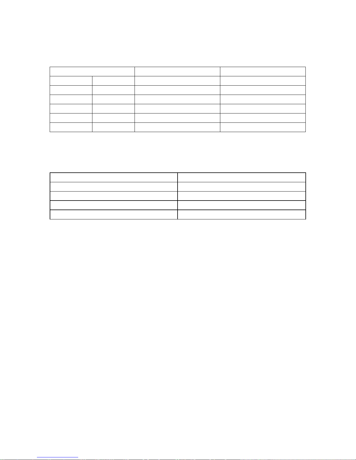
7. Operation Characteristics
Temperature
Mode
Cooling operation Heating operation Drying operation
Room temperature
≥17℃ ≤30℃ >10℃
Outdoor temperature
0℃~50℃
-15℃~30℃ 0℃~50℃
-15℃~50℃
(For the models with
low temperature
cooling system)
CAUTION:
1. If the air conditioner is used beyond the above conditions, certain safety protection features
may come into operation and ca use t he unit to operate abnormally.
2. The room relative humidity should b e less t han 80%. If the air conditioner operates beyond this
figure, the surface of the air conditioner may attract condensation. Please set the vertical air flow
louver to its maximum a ngle (vertically to the floor), and set HIGH fan mode.
3. The optimum performance will be achieved during this oper at ing temperature zone.
Page 26

26
8. Electronic function
8.1 Abbreviation
T1: Indoor room temperature
T2: Coil temperature of evaporator
T3: Coil temperature of condenser
T4: Outdoor ambient temperature
TP: Compres sor discharge temperature
8.2 Display function
8.2.1 Icon explanation on indoor display board.
Each time the “DISPLAY” button of remote controller is pressed, the displ ay area displays in a
sequence of following:
Room temp. Outdoor ambient temp.
Setting temp. Display turns off
NOTE:
If the indoor/outdoor temperature sensor is failure, it will not display the indoor/outdoor
temperature.
Under inquiring, the indoo r temperatur e flashes at 0.5HZ, and outdoor t empera ture flashes at
1HZ. If there is no button operation during 15 seconds, the set temperature wi ll rev ert back to
the display window.
The actual room temperature and outside temperature can be displayed in a range of
-9.5℃-70 ℃
Displays the malfunction code.
Page 27

27
8.3 Main Protection
8.3.1 Three Minutes Dela y at restart for compressor
1 minute delay for the 1
st
time start-up and 3 minutes delay for others.
8.3.2 Temp erature protection of compressor top
The unit will stop working when the compressor top temp. protector cut off, and will restart after
the compressor top temp. pr otect or restart.
8.3.3 Temperature pr ot ection of compressor di scharge
When the compressor discharge temp. is getting higher, the running frequency will be limited as
below rules:
---Compressor discharge t em p. T5>115℃ for 9s, compressor stops.
---110<T5<115℃, decrease the frequency to the lower lev el every 2 minutes.
---105<T5<110℃, keep running at the current frequency.
----T5<90℃, no limit for frequency.
8.3.4 Fan Spe ed is out of control
When Indoor Fan Speed keeps too low (lower than 300RPM) or too high(higher than 2100RPM)
for certain time, the unit w i ll stop and the LED will display the failure
8.3.5 Inverter module Pr otect i on
The Inverter module has a protection function about current, voltage and temperature. If these
protections happen, the corresponding code will display on indoor unit and the unit will stop
working.
8.3.6 Indoor fan delayed open functio n
When the unit starts up, the louver will be active immediately and the indoor fan will open 10s
later.
If the unit runs in heatin g mo de, t he indoor fan will be also controlled by ant i-cold wind function.
8.3.7 Compress or preheating functio ns
Preheating permitting condition:
If T4(outdoor ambient temperature)<T4preheat℃ and T1<18℃, the compressor heating cable
will work.
Preheating mode:
A weak current flow through the coil of compressor from the wiring terminal of the compressor,
Page 28

28
then the compressor is heat ed w ithout operation.
Preheating release condition:
If T4≥3℃ or T1≥18℃, the prehe at ing function will stop.
8.3.8 Zero crossi ng detection error protection
If AC detects time interval is not correct for continuous 240s, the unit will stop and the LED will
display the failure. The correct zero crossing signal time inter val should be between 6-13ms.
8.3.9 Sensor protection at open circuit and breaking disconnect ion.
When there’s one temperature sensor in malfunction, the air conditioner will display error code
and will not stop immediately, to avoid the case that the air conditioner is in urgent need.
Fault temp.
sensor
Operation in cooling, dry ing and
fan only mode
Operation in heating mode
T1
Run supposed T1=26℃ high fan
speed
Run supposed T1=26℃ high fan
speed
T2
Refer to table 1
Refer to table 2
T3
Run with compressor freq uency
not higher than F14
3 minutes’ defrostin g every 40
minutes when T4<7℃; 2 minutes’
defrosting every 90 minutes w hen
T4≥7
℃
.
T4
Run supposed T4=50℃
Run supposed T4=15℃
TP
Run supposed T4=50℃
Run supposed T4=15℃
T1
25
23
F12
F4(30 minutes on+3
minutes off)
table 1
T1
20
18
F4
F12(Indoor fan 1 minute
off, 1 minute M- ane then
the setting fan speed.)
table 2
8.4 Operation Modes and Functions
8.4.1 Fan mode
(
1) Outdoor fan and compressor stop.
(2) Temperature setting function is disabled. And the display window shows the indoor room
Page 29

29
temperature.
(3) Indoor fan can be set by remote controller
from 1% to 100%.
(4) The louver operates same as in cooling mode.
(5)The auto fan in fan mode is running as auto fan of cooling mode with 24
℃ setting
temperature.
8.4.2 Cooling Mode
8.4.2.1 Compressor running rules
The maximum operation frequency of compressor after starting submits to the following rule. The
maximum operation frequency is limited by outdoor ambi ent t em p.
t11
t12
t13
t14
t15
t16
t17
t18
Fmax= T4FREMAX1
t19
t20
t21
t22
Fmax= T4FREMAX2
Fmax= T4FREMAX3
Fmax= T4FREMAX4
Fmax= T4FREMAX5
Fmax= T4FREMAX6
Fmax= T4FREMAX7
Also the maximum freque ncy is limited by the indoor fan speed:
Indoor fan speed
Maximum frequency
80%-100%
No limit
60%-79%
FCoolMaxMidFan
40%-59%
FCoolMaxLowFan
1%-39%
FQCoolMax
Page 30

30
If users switch on AC by remote controller, the compressor will run at the Fmax frequency for
several minutes. Then the compressor running frequency will be contr olled as below:
3.5
3.0
2.5
2.0
1.5
1.0
0.5
-0.5
T1-Ts
-1.0
A
B
C
D
E
F
G
H
-1.5
0.0
I
J
While the zones of A,B,C... are corresponding to di fferent compressor running frequency.
Meanwhile, the compressor running frequency is limited by t he cur r ent.
ISTOPCOOL
I
Icmax
Off
Decrease
Hold
Resume
Icmax-I1COOL
Off: Compressor stops.
Decrease: Decrease the r unning frequency to the lower level.
Hold: Keep the curre nt frequency.
Resume: No limitation for frequency.
While the Icmax is limited by the outdoor ambient temp er at ur e as below:
Page 31

31
50
49
45
44
41
40
Icmax= I2COOL
Icmax= I3COOL
Icmax= I4COOL
Icmax= I5COOL
8.4.2.2 Outdoor fan running rules
22
20
High
Low
8.4.2.3 Indoor fan running rules
In cooling mode, indoor fan r uns al l t he t i me a nd t he speed can be selected from 1% to 100%.
If the indoor unit changes from off to auto fan, the indoor fan will run at 100% for 5 minutes, then
follow the below rules.
Page 32

32
Auto fan:
2.0
T1-Ts
100%
80%
60%
40%
1%
1.5
1.0
0.5
0.0
-0.5
-1.0
90%
20%
8.4.2.4 Condenser temperature protection
TP4
T3
TP3
Off
Decrease
Hold
Resume
TP2
Off: Compressor stops.
Decrease: Decrease the r unning frequency to the lower level.
Hold: Keep the curre nt frequency.
Resume: No limitation for frequency.
8.4.2.5 Evaporator temperature protection
---T2<0℃, the compressor will stop and r estart when T2
>=5℃.
---0℃≦T2<4℃, the compressor frequency will be limited and decreased to the lower lev el
---4℃≤T2≤7℃, the compressor will keep the current frequency.
---T2>7℃, the compressor frequency will not be limited.
8.4.3 Heating Mode
8.4.3.1 Compre ssor running rules:
The maximum operation frequency of the com pr essor after starting submits to the following rule.
Page 33

33
Fmax=F6
Fmax=F10
Fmax=F14
Fmax=F18
Fmax=F20
Fmax=F16
Fmax=F12
Fmax=F4
34
Off
33
28
27
25
24
22
21
19
18
16
17
15
14
Fmax=F8
12
11
6.0
5.0
Fmax=F21
Fmax=F22
Fmax=F23
Fmax=F24
Fmax=F25
1.0
0.0
-3.0
-4.0
-7.0
-8.0
-11.0
-12.0
-15.0
-16.0
Also the maximum freque ncy is limited by the indoor fan speed:
Indoor fan speed
Maximum frequency
80%-100%
No limit
60%-79%
FHeatMaxMidFan
40%-59%
FHeatMaxLowFan
1%-39%
FQHeatMax
If users switch on AC by remote controller, the compressor will run at the Fmax frequency for
several minutes according to outdoor ambient temp.
Then the compressor running frequency w ill be controlled as below:
Page 34

34
+5.0
+4.5
+3.5
+3.0
+2.5
+2.0
+1.5
T1-Ts
+1.0
J
G
F
E
D
C
B
A
+0.5
I
H
While the zones of A,B,C... are corresponding to differ ent compressor running frequency.
Meanwhile, the compressor running frequency is limited by t he current.
ISTOPHEAT
I
I2HEAT
Off
Decrease
Hold
Resume
I1HEAT
Off: Compressor stops.
Decrease: Decrease the r unning frequency to the lower level.
Hold: Keep the current frequency.
Resume: No limitation for frequency.
Page 35

35
8.4.3.2 Outdoor fan running rules
17
15
Low
High
8.4.3.3 Indoor fan running rules
Indoor fan speed can be set from 1% to 100% and the anti-cold-wind function is preferential.
The run ning r ules of anti-cold-wind function depend on both T1 and T2 that is more comfortable
control.
Auto fan action in heating mode:
6.0
T1-Ts
100%
80%
60%
40%
1%
5.5
5.0
4.5
4.0
8.4.3.4 Defrosting mode
Condition of defrosting:
If any one of the following items is s at is fi ed, AC will enter the defrosting mode.
After the compressor starts up and keeps running, mark the minimum value of T3 from the 7th
minutes to 12th minutes as T30.
1)If the compressor cumulate running time is up to 29 minutes and T3< TCDI1, T3+
T30SUBT3ONE≦T30.
2)If the compressor cumulate running time is up to 35 minutes and T3< TCDI2, T3+
T30SUBT3TWO≦T30.
3)If the compressor cumulat e r unni ng t ime is up to 29 minutes and T3< TCDI3 for 3 minutes.
4)If the compressor cumulat e r unning time is up to 120 minutes and T3<-15℃.
Page 36

36
5)For the first time defrosting af t er t he unit s tarts operation newly, if it meets all of the below rules:
a: AC is ru nning in heating mode.
b:After the AC operates for 30 minutes, if the T4- T3 >f(T4)=0.5T4+ KDELTTT.
c:T3<-5℃
Condition of ending defrosting:
If any one of the following items is satisfied, the defrosting will finish and the machine will turn to
normal heating mode.
----T3 rises to be higher than TCDE1℃.
----T3 keeps to be higher than TCDE2℃ for 80 seconds.
----The machine has run for 15 minutes in defrosting mode.
Defrosting action:
Compressor
on
off
on
on
on
off
off
off
4-way valve
Outdoor fan
Indoor fan
20
no longer than 15m
20s
10s
10s
Page 37

37
8.4.3.5 Evaporator coil temperature protection
TEstop
T2
Off
Decrease
Hold
Resume
TEdown
TEnorm
8.4.4 Auto-mode
This mode can be chosen with remote controller and the setting temperature can be changed
between 17~30℃.
In auto mode, the machine will choose cooling, heating or fan-only mode according to ΔT (ΔT
=T1-Ts).
ΔT=T1-Ts Running mode
ΔT>2℃
Cooling
-3<ΔT≤2℃
Fan-only
ΔT≤-3℃
Heating
Indoor fan will run at auto fan of the relevant mode.
The louver operates same as in rel evant mode.
If the machine switches mode between heat ing and cooling, the compressor will keep stopping for
20 minutes and then choose mode according to T1-Ts.
If the setting temperature is modified, the machine will choose running function again.
8.4.5 Drying mode
8.4.5.1 Indoor fan speed is fixed at auto fan of cooling mode and can’t be changed. The louver
angle is the same as in cooling mo de.
8.4.5.2 Compressor running rules
Page 38

38
2.0
1.5
1.0
T1-Ts
Rated frequency
F10
F8
F6
2.5
0.5
0.0
8.4.5.3 Low indoor room t em per at ure protection
In drying mode, if room temperature is lower than 10℃, the compressor will stop and not resume
until room temperature ex ceeds 12℃.
8.4.5.4 Evaporator anti-freezing protection, condenser high temperature protection and outdoor
unit frequency limit are act ive and the same as that in cooling mode.
8.4.5.5 The outdoor fan operates the same as in cooling mode.
8.4.6 Forced operation funct i on
8.4.6.1 Enter forced operation function:
When the machine is off, pressing the touch button will carry the machine to forced auto mode.
After this, pressing the button once again within 5 seconds, the machine will turn into forced
cooling mode.
In forced auto, forced cooling or any other operation mode, pressing touch button will turn off the
machine.
8.4.6.2 In forced operation mod e, all general protections and remote co nt rol are available.
8.4.6.3 Operation rules:
Forced cooling mode:
The compressor runs at F2 frequency and indoor fan runs at 20%. After running for 30 minutes.
the machine will turn to auto mode as 24℃ setting temperature.
Forced auto mode:
The action of forced auto mo de i s t he s ame as normal auto mode with 24℃ setting temperature.
Page 39

39
8.4.7 Timer function
8.4.7.1 Timing range is 24 hours.
8.4.7.2 Timer on. The machine will tur n on aut omatically when reaching the sett ing time.
8.4.7.3 Timer off. The machine will turn off automatically when reaching the setting time.
8.4.7.4 Timer on/off. The machine will turn on automatically when reaching the setting “on” time,
and then turn off auto matically when reaching the setting “off” time.
8.4.7.5 Timer off/on. The m achi ne will turn off automatically when reaching the setting “off” time,
and then turn on automatically when reaching the setting “on” time.
8.4.7.6 The timer function will not change the AC current operation mod e. Suppose AC is off now,
it will not start up firstly after setting the “timer off” function. And when reaching the setting time,
the timer LED will be of f a nd t he AC running mode has not been changed.
8.4.7.7 The setting time is r elat iv e t ime.
8.4.8 Intelligent sleep mode
This function is only available in cooling mode and heating mode.
Two kinds of sleep modes are
optional. Press “FUNCTION” button to select.
Sleep mode A:
Running time in sleep mode is 8 hours. 8 hours later, AC will quit sleep mode and the setting
temp. decrease 1℃ for cooling mode or increase 1℃ for heating mode.
● When cooling, the setting temper at ur e r i ses 1℃(be lower than 30℃) every one hour, 2 hours
later the setting temperatur e stops rising.
When heating, the s etting temper ature decre ases 1℃(be h ig her than 17℃) e ver y one hour, 2
hours later the setting temperat ur e st ops changing .
● The indoor fan runs at auto speed.
Sleep mode B:
Page 40

40
● Running time in sleep mode is 9 hours. 9 hours later, AC will quit sleep mode.
● When cooling, the default setting te m per at ure is 25℃ which will increas e 1 ℃ every one
hour,2 hours later the setting temperature st ops rising.
● When heat ing, the default setting temperature is 22℃ which will decrease 1 ℃ every one
hour, 2 hour s l at er t he s et t ing temperature stops changing.
● If the setting temper ature i s chang ed duri ng X hour s, it w ill be memorized and enab le d as the
setting temperature of X~9 hours in the next t ime r unning while the setting temperature in the X-1
hours will not change.
● The indo or fa n r uns at auto speed.
8.4.9 I mode
The “I mode” is used to restore the current settings or resume previous settings. Under cooling or
heating operation, push the “i mode” button of remote controller for more than half and one
second, the system will restore the current operation settings including operating mode, setting
temperature, fan speed level and sw ing f eature(if activat ed ). On the f irst time pressing th is button,
the unit will operate on COOL mode, 26 ℃(or HEAT mode, 20 ℃), and fan speed is auto.
8.4.10 Low-frequency operation with auto fan
This function is only available in cooling mode. Press “FUNCTION” button , then press the
“ADJUST“ to
and select “OK”. Then the function will be active.
During the function, the maximum running frequency will be limited and the indoor fan speed is
auto which is more energy -saving.
8.4 11 Dry and Self clean function
When the unit is turned off, it will run in fan only mode for 7 minutes, then run heat mode with low
fan for 1 minute, and then run fan only mode for 2 minutes. This function can prov ide you clean air
Page 41

41
and keep you healthy.
Hydrophilic golden fin with ant i-oi l pollution and anti dust feature
Condensed water flows thr ough evaporator, and takes away oil and dirt.
8.4 12 Auto-Restart function
The indoor unit is equipped with auto-restart function, which is carried out through an auto-restart
module. In case of a sudden power failure, the module memorizes the setting conditions before
the power failure. The unit will resume the previous operation setting (not including swing function)
automatically after 3 m inutes when power returns.
If the memorization condition is forced cooling mode, the unit will run in cooling mode for 30
minutes and turn to auto mode as 24℃ setting temp.
If AC is off before power off and AC is required to st ar t up now, the compressor will have 1 minute
delay when power on. Other conditions, the compressor will have 3 minutes delay when it
restarts.
Page 42

42
9. Troubleshooting
9.1 Indoor Unit Error Display
Display LED STATUS
E0
EEPROM parameter er r or
E1 Indoor unit and outdoor unit communication protection
E2 Zero-crossing signal detection error
E3 Indoor fan speed has been out of co nt r ol
E5 Open circuit or short circu i t of outdoor temperature sensor
E6 Open circuit or short circu i t of room or evaporator coil temperat ur e sensor
P0 IPM malfunction or IGBT over-strong current protection
P4 Inverter compressor drive error
Page 43

43
9.2 Diagnosis and Solution
9.2.1 EEPROM parameter error diagnosis and solution(E0)
If the EEPROM chip
is welded on main
PCB, replace the
main PCB directly.
Otherwise, check
whether the
EEPROM chip
plugged in main PCB
well?
Yes
No
Yes
Correct the connection.
Replace the indoor main
PCB.
Shut off the power supply and
turn it on 5 seconds later. Is it
still displaying the error code?
EEPROM: a read-only memory whose contents can be erased and repro gra mme d using a pu lsed
voltage.
Page 44

44
9.2.2 Indoor / out door units communication error diagnosis and solutio n(E1)
Yes
Yes
Measure Vs, is it moving alternately
between positive value and negative
value?
(Vs is the voltage between S and N of
outdoor unit.)
Yes
Power off, then turn on the unit 5 seconds
later(reconnect the power wire).Is the error
still displaying after several minutes?
No
Yes
Change the outdoor main PCB.
Power on. Is the error extinguished?
Check all the wirings between indoor and
outdoor, indoor main PCB and outdoor main
PCB following the wiring diagram. Are all
the wirings connected correctly?
Is the wiring to the indoor main
PCB connected correctly?
Change the indoor main PCB.
Yes
Change the outdoor main PCB.
No
Is the wiring to the outdoor main
PCB connected correctly?
Power on. Is the error extinguished?
Change the indoor main PCB.
No
Page 45

45
9.2.3 Zero crossi ng detection error diagnosis and solution(E2)
Check if the connections and
power supply is normal?
Correct the connections. Turn on the
unit when the power supply is good.
No
Yes
Indoor main PCB is
defective. Replace indoor
main PCB.
Page 46

46
9.2.4 Indoor fan speed has been out of control diagnosis and soluti on(E3)
Shut off the power supply
and turn it on 5 seconds
later. Is it still displaying
the error code?
Shut off the power supply,
rotate the fan by hand.
Does it rotate properly?
The unit operates normally.
Find out the cause and
have it solved. For
example, check
whether the fan is
blocked or the bearing
is broken?
Check the wires of fan
motor. Are all the
connections good?
No
Yes
No
Correct the connections.No
Yes
Check whether the main PCB is
normal through index 2?
Yes
Yes
Check whether the fan
motor is normal through
index 1?
Yes
Replace the fan
motor
Replace the
main PCB.
The
malfunction is
solved?
No
No
If the
malfunction is
still existing,
replace the
main PCB
No
Page 47

47
Index 1:
1.Indoor AC Fan Motor
Measure the resistanc e value of each winding by using the tester.
Index2:
1: Indoor AC Fan Motor
Power on and set the unit running in fan mode at high fan speed. After running for 15 seconds,
measure the voltage of pin1 and pin2. If the value of the voltage is less than 100V(208~240V
power supply)or 50V(115V power supply), the PCB must has problems and need to be replaced.
Page 48

48
9.2.5 Open circuit or short circuit of temperature sensors diagnosis and
solution(E4/E5/F1/F2/F3)
Check the connections
between temperature
sensor and main PCB.
Are the connections
good?
Correct the connections.
No
Yes
Yes
Replace indoor or outdoor main
PCB.
Replace the sensor and
check if the problem
happen again?
Check the resistance value
of the sensor via table1
and table 2, is it normal?
No
Page 49

49
9.2.6 IPM malfunction or IGBT over-strong current diagnosis and solution(P0)
Check if the wiring between main
PCB and compressor connected by
error and if the wires and connectors
are broken?
Correct the connection or
replace the wires and
connectors.
Yes
No
Check if the IPM installed correctly.
Correct the installation,
tighten the screws and
apply silicon grease.
No
IPM continuity check. Check if the
IPM terminal resistance values are
uniform.
Yes
Replace the IPM board or replace
the main PCB if the IPM board and
main PCB are integrated together.
No
Check if the outdoor fan runs
properly or the outdoor unit
ventilation is good.
Yes
No
Refer to the solution of fan speed
has been out of control
malfunction . Find out the cause
and have it solved.
Yes
Check if the compressor resistance
values are uniform .
No
Replace the compressor.
Yes
Replace the outdoor main PCB if the
main PCB and IPM are separate.
Page 50

50
9.2.7 Inverter compressor drive error diagno s i s and solution(P4)
Check if the wiring between main
PCB and compressor connected by
error and if the wires and connectors
are broken?
Correct the connection or
replace the wires and
connectors.
Yes
No
Check if the IPM installed correctly.
Correct the installation,
tighten the screws and
apply silicon grease.
No
IPM continuity check. Check if the
IPM terminal resistance values are
uniform.
Yes
Replace the IPM board or replace
the main PCB if the IPM board and
main PCB are integrated together.
No
Check if the outdoor fan runs
properly or the outdoor unit
ventilation is good.
Yes
No
Refer to the solution of fan speed
has been out of control
malfunction . Find out the cause
and have it solved.
Yes
Check if the compressor resistance
values are uniform .
No
Replace the compressor.
Yes
Replace the outdoor main PCB if the
main PCB and IPM are separate.
Page 51

51
Safety
Electricity power is still kept in capacitors even the power supply is shut off. Do not forget to discharge the
electricity power in capacitor.
Electrolytic Capacitors
(HIGH VOLTAGE! CAUTION!)
Connect discharge resi st an ce ( approx.100Ω 40W) or soldering iron (plug) between +, - t er mina ls of t he electrolytic
capacitor on the contrary side of the outdoor PCB.
Note: The picture above is only for reference. The plug of your side may be different.
Main parts check
1. Temperature sensor checking
Disconnect the temperature sensor from PCB, measure the resistance value with a tester.
Page 52

52
Temperature Sensors.
Room temp.(T1) sensor,
Indoor coil temp.(T2) sensor,
Outdoor coil temp.(T3) sensor,
Outdoor ambient temp.(T4) sensor,
Compressor discharge temp.(TP) sensor.
Measure the resistance value of each winding by using the multi-meter.
Table 1:Some frequently-used R-T data for T1,T2,T3 and T4 sen sor:
Temperature (℃) 5 10 15 20 25 30 40 50 60
Resistance Value (KΩ) 26.9 20.7 16.1 12.6 10 8 5.2 3.5 2.4
Table2:Some frequently-used R-T data for TP sensor:
Temperature (℃) 5 15 25 35 60 70 80 90 100
Resistance Value (KΩ) 141.6 88 56.1 36.6 13.8 9.7 6.9 5 3.7
Resistance value (KΩ)
Temperature (℃)
TP
T1,T2,T3,T4
Page 53

53
Spec.
Code 2T0032300776 2T0032400215
Indoor code 220032308300 220032402810
Indoor MSIC-09HRDN1-QC2 MSIC-12HRDN1-QC2
Outdoor code 220037305880 220037401990
Outdoor MOR-09HDN1-QC2 MOR-12HDN1-QC2
Compressor DA89X1C-23EZD1 DA89X1C-23EZD1
Indoor fan motor RPG20E RPG20E
Outdoor fan motor YDK24-6P(B) YDK24-6P(B)
2. Compressor checking
Measure the resistance value of each winding by using the tester.
Position Resistance Value
DA89X1C-23EZD1
Blue - Red
1.1Ω
(20℃)
Blue - Black
Red - Blue
Page 54

54
3.IPM continuity check
Turn off t he pow er, let the large capa city e lectroly tic ca pa citors di scharge comple tely, and dismount the IPM. Use a
digital tester to measure the resistance between P and UVWN; UVW and N.
Digital tester
Normal resistance
value
(+)Red
(-)Black
∞
(Several MΩ)
P
N U V
W
Digital tester Normal resistance value
(+)Red (-)Black
∞
(Several MΩ)
U
N
V
W
4.Indoor AC Fan Motor
Measure the resistance value of each winding by using the tester.
Position Resistance Value
RPG20E
Black - Red
430Ω±8% (20℃)
White - Black 370Ω±8% (20℃)
 Loading...