

Page 1

1
Technical Service
Manual
French Door Refrigerator
HC-702WE
Page 2

2
Content
Chapter 1: Functions and Characteristics
Chapter 2: Technical Parameters
Chapter 3: Cycle Diagram of the System
Chapter 4: Electric Schematic Diagram and Circuit
Wiring Diagram
Chapter 5: Guide for Maintenance of R134a Refrigerator
Chapter 6: Failure Predication Flow Chart
Chapter 7: Exploded View of the Product and Parts List
Page 3

3
Chapter 1: Functions and Characteristics
Midea Brand
● DC frequency conversion technology;
● Double evaporator system, chill and refrigerate food separately, so as to
prevent from tainting by odor;
● High moisture system, with moisture rate up to 80%, so as to increase the
freshness retaining of fruits and vegetables;
● Mute design; noise level≤45dB;
● According to the actual frequency of usage, intelligent defrosting is adopted
for the frosting speed, which is better for energy saving;
● Thermostatic preservation technology, with independent air circulation
system designed in the chilling chamber, so that the temperature can be
independently controlled, the storage temperature is stable, and the freshness
of food can be retained longer.
Page 4
4
Chapter 2: Technical Parameters
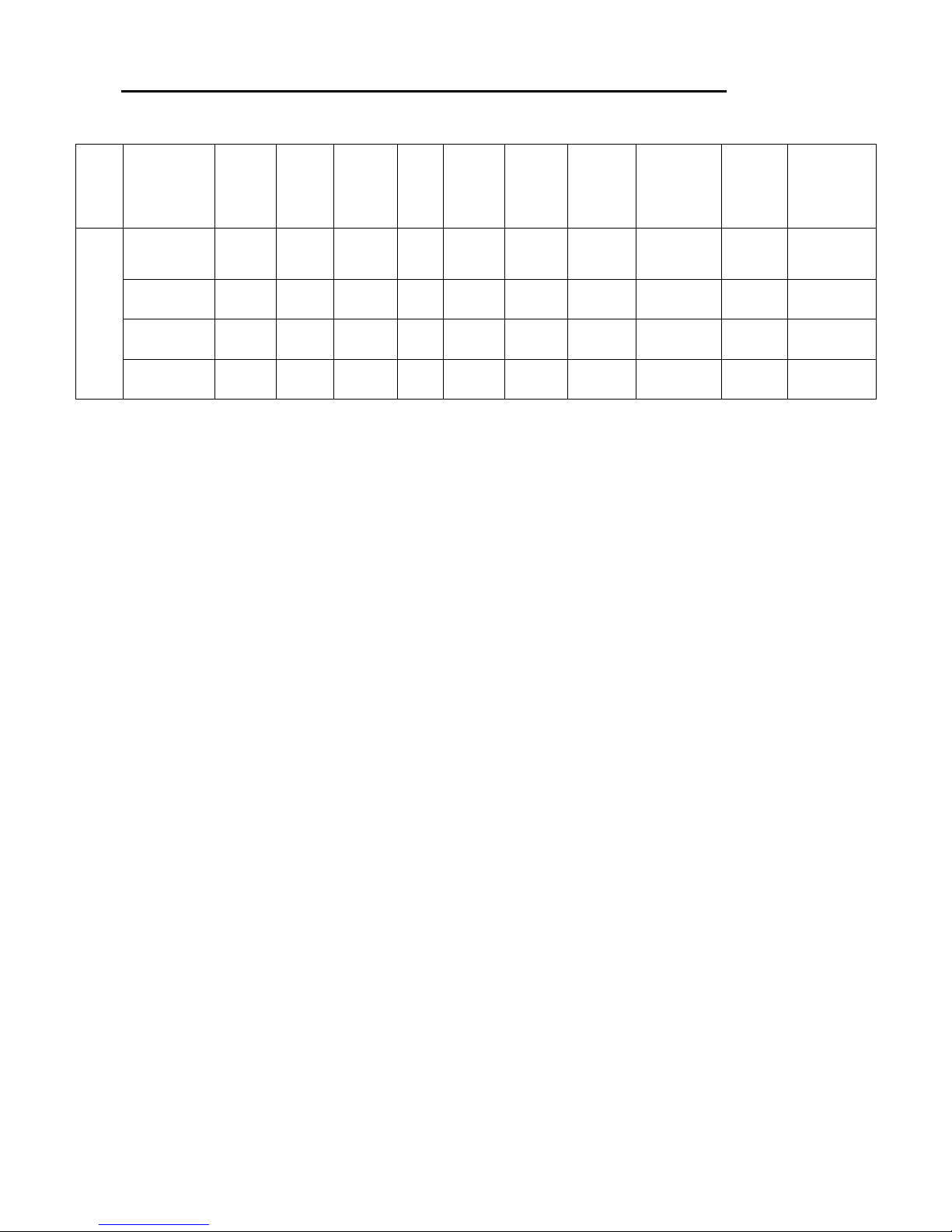
1.
Specifications and main parameters of Midea Brand
Series
Model
Effective
/refrigera
tion
(L)
Climate
type
Refrigerat
ing
capacity
(kg/24h)
Net
weight
(kg)
Product
size
(mm)
Power
consump
tion
(kW·h/24h
)
Energy
consum
ption
grading
Compressor
Temp.
control
Refrigerant/in
jection rate
(g)
HC-702WE
540/420
T 10 137
911×728.
5×1775(
without
handles)
1.18 A+
Embraco
VEGZ7H
Computer R134a/180
Dual system
refrigerator
Page 5
5
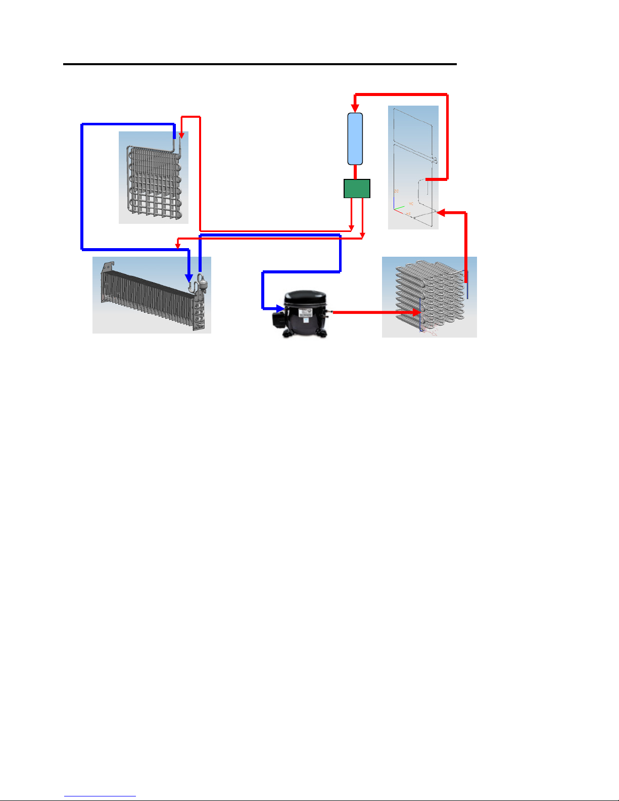
Chapter 3: Cycle Diagram of the System
Applicable for: HC-702WE (economic development zone)
The size on the drawing is a theoretical size, and it is different from full size.
Compresso
Condenser
Dew eliminating tube
Chilling capillary
Freezing capillary
Freez
ing evaporator
Chilling evaporator
Dry Filter
Solenoid valve
Page 6

6
Chapter 4: Electric Schematic Diagram
and Circuit Wiring Diagram
Electric schematic diagram:
Circuit wiring diagram:
11
1287
CN
2
3
4
CN14
CN13
5
7
8
JM
32
4
1 3
5
CN
1
CN15
8
1
2
CN 16
541
1 2
3
6
3
7
6
1
32
5 4
10
9
2
1
3
21
6
CN
11
1 3 5
7 9
3
42
1
3
4
2
1
2
1
1 2
3
4
2
4
67
1
234
123
4 5
1
2 3
3
2 1
1 2 3
1 3
CN
6
5
6
2
4
3131
CN3CN
4
12 43 65 87 12 43 651
CN
5
22
4 6
8 10
CN12
541 32 67
1
2
3
CN10
9 8 7
6 5
4 3 2
1
GM
CN9
5
4
1 32 6
10
11
9
CN7
变温室控制板
5
6
2
blackblack
red
yellow
white
blue
cyan
purpleorange red whiteblack
blue
yellowbrown
greenpink
blue/white
gray
control circuit board
red
white
white
white
white
white
white
white
red
red
red red
red
red red
blue
blue
blue
blue
blue
blue
blue
blue
blue
black
black
black
black
black
black
black
black
yellow
yellow
yellow
yellow
yellow
yellow
gray
gray
gray
purple
purple
purple
purple
purple
pink
pink
orange
orange orange
brown
brown
white cyan
cyan
cyan
tawny
tawny
tawny
red
white
pink
blue
purple
door display panel
black
white
ambient
temperature sensor
inlet pipe heater strip
compressor frequency
conversion board
brown blue
black
brown
blue
fan electromotor
black
black
red red
purple
purple
defrost sensor
chilling chamber
sensor
chilling chamber ceiling lamp
chilling chamber side lamp
chilling chamber side lamp
chilling chamber
temperature-variable
chamber
temperature-variable
chamber sensor
UV-LIGHT WAVE PRESERVING LAMP
temperature-variable
chamber motorized
operated damper
fuse
chilling chamber defrosting heater
door turnover beam heater
door turnover beam component
defrost sensor
red
red
purple
purple
black
black
black
black
purple
purple
purple
purple
red
red
red
red
fan electromotor
chilling chamber sensor
fuse
refrigerating defrost heater
white
white
yellow
yellow
blue
blue
blue blue
blue
blue
ice maker electric machine
switch
ice maker water
pump
refrigerating
ceiling lamp
yellow-green
yellow-green
yellow-green
yellow-green
electric
changeover
valve
compressor
brownblueblack
yellow-green
filter
brown/
white
blue
/white
yellow
/green
brown
blue
cool chamber
tawny
tawny
yellow-green
yellow-green
This wiring diagram is applicable for: the Midea Brand refrigerator produced in the economic
development zone
Page 7

7
Chapter 5: Guide for Maintenance of
R134a Refrigerator
I. Property of the R134a refrigerant
R134a, also named as tetrafluoroethane, is one of the hydrofluorocarbon (HFC for short), The
molecular weight of it is 102, and its structural formula is CH2FCF3. It is colorless transparent liquid,
without turbidity and foreign odor. Its ozone depleting potential (ODP: ozone depletion potential) = 0. and
its greenhouse effect potential (GWP: global warming potential) = 1300. ASHRAE safety class: A1. I is
non-toxic and non-flammable.
II. Maintenance technology of R134a refrigerator
1. General requirement: no matter whether there is leakage of the system, reliable earthing for all the
equipment is necessary when filling the refrigerant, so as to avoid sparks resulting from possible static
electricity. Besides, all the wiring must be firm, and wrong wiring is not permitted.
2. Firstly, check whether there is fire source around, and keep favorable ventilation;
3. Get the equipment and fittings ready which are specially used for maintenance;
4. Check the safety of maintenance equipment and main supply;
5. Check whether there is leakage, loose for the emptying clamp, and adjust it to the proper position;
6. Lead the exhaust pipe to the outdoor, get the emptying clamp stuck at the dry filter, start the
compressor, and stop after 5-minute operation. Vibrate the compressor, so as to discharge the
isobutane dissolved with lubricating oil. After 3-minute suspension, re-plug to operate for 5 minutes, so
as to minimize the isobutane content in the pipe system;
7. Cut off the power supply, seal the air vent of dry filter, get the special emptying clamp stuck at the low
voltage tube of the compressor, use the R134a vacuum pump to evacuate, and operate for 10 minutes;
8. Remove the compressor, dry filter using pipe cutter, and adopt nitrogen to blow the pipe for more than
5 seconds;
9. Change the R134a compressor, dry filter, and weld each interface by gas welding;
10. Blow the nitrogen to check the leakage, with nitrogen pressure no larger than 0.8Mpa, and use soap
water to check the leakage;
11. Discharge the nitrogen, and evacuate for more than 20 minutes, so that the vacuum degree will
reach up to specified value;
12. In order to ensure the accuracy of recharge, electronic scale shall be adopted for the weighting
during the filling. Plug the refrigerator to operate;
13. There is no abnormal seal;
14. Use suds to check leakage of the seal;
15. Plug the refrigerator to operate, and test its performance.
III. Precautions
1. If it is required to change the compressor during repair, the recharged amount shall be specified value;
no need to change the compressor, the recharged amount shall be 90% of the specified value.
2. It is not advisable to open the refrigerating system to operate at home by the users in principle,
because it is dangerous.
IV. Servicing installation and tools
1) R134a evacuating placer
2) Electronic scale
3) Emptying clamp
4) Sealing clamp
Page 8

8
Chapter 6: Flow Chart of Refrigerator
Failure Predication
● For different products, there is some difference for the predication of failure, thus, it is un-necessary to
explain each point clearly.
● For products with inleakage and in need of repair, excavate the foaming material according to the
pipeline location drawing in Chapter 3. Carry out repair welding for the inleakage point, and conduct
pressure maintaining and leakage detecting. No leakage found, fill it with foaming material.
Figure -1
Use oscilloscope to
check whether
signal is output here
abnormal operation
of refrigerator
check the power
supply and voltage
electroless
too low voltage
check the
plug and
socket fuse
check indoor
power circuit
normal
The compressor
can be started and
Whether the display
displays normally,
whether there is
trouble code
yes
yes yes
yes yes
yes
yes
yes
yes
yes
no
no
no
no
no
no
no
no
no
Firstly, eliminate the
trouble according to
the trouble code
and instruction.
no
See Figure-4
See Figure-5
See Figure-1
See Figure-2
See Figure-3
The
compressor
fails to start
display and light
off
display and light on
check the
power line
Use the oscilloscope to
check whether there is
signal sent out from the
main control panel
poor refrigeration of
chilling chamber
poor refrigeration
of refrigerating
chamber
Whether the chilling
chamber blower fan
works normally
Whether the
refrigerating chamber
blower fan works
normally
Whether the chilling
chamber defrosting
heater is normal
Check the chilling
blower fan circuit
or change the
chilling blower fan
Whether the
refrigerating
defrost heater is
normal
Check the refrigerating
blower fan circuit or
change the chilling
blower fan
Check the heater
circuit or change the
chilling chamber
Check whether the
electric changeover
valve works normally
Check the heater
circuit or change the
refrigerating defrost
heater
Check which one is
larger, the compressor
power or the rated
power
smaller
smaller
larger
larger
Check the electric
valve circuit or
change the electric
changeover valve
Check which one is
larger, the compressor
power or the rated
power
There is insufficient
coolant in the
system, and refilling
is required
There is insufficient
coolant in the
system, and refilling
is required
The system pipeline is
blocked up. Find out
the blocking point,
weld and refill again
The system pipeline is
blocked up. Find out
the blocking point,
weld and refill again
abnormal operation
of the
temperature-variabl
e chamber
whether the
temperature of
temperature-variable
chamber is normal
on the high side on the low side
the temperature-variable air
duct is blocked up or the
temperature-variable
damper is not open
temperature-varia
ble damper opens
all the time and
cannot be closed
clear out the foaming material in
the temperature-variable air
duct, or check the damper
circuit and change the
temperature-variable damper
change the
temperature-vari
able damper
poor refrigeration
of the chilling and
refrigerating
chamber
whether the chilling
chamber blower
fan works
there is no sound of
flowing coolant at
the inlet of
evaporator
check the
condensate fan or
change the blower
fan
very low power
dissect the process
tube after closing
down
master control
board trouble
change the
master control
board
check whether there
is voltage output from
the frequency
conversion board
check whether the
frequency
conversion board
and compressor
connector are
correctly erected
frequency
conversion board
trouble
change the
frequency
conversion board
wrong terminal
linear ordering may
cause compressor
trouble easily
compress
or trouble
change the
compressor
change the
compressor
change the
compressor
there is
no
liquid ejected
there is liquid
ejected
all the coolant
is leaked
find out the
leakage point,
pump out and
refill the coolant
restarted, there
is no suction at
the cutting
restarted, there
is suction at the
incision
compressor is
out of work
there is blockage on
the high voltage side
clear the blockage,
evacuate and refill
the coolant.
Page 9

9
Figure -2
Figure -3
Figure -4
Sensor failure Failure code Remarks
Chilling chamber E1
Refrigerating chamber E2
Incasement sensor failure
Temperature-variable
chamber
E3
Chilling defrost sensor E4 Defrost sensor failure
Refrigerating defrost sensor E5
Ambient temperature sensor
failure
Ambient temperature
sensor
E7
Communication failure - E9
High temp. alarm of
refrigerating chamber
- EA
Figure -5
Rated power table of refrigerator in different ambient temperature
Scope of ambient temperature
Below 22℃℃℃℃ 22~28℃℃℃℃ 28~35℃℃℃℃ Over 35℃℃℃℃
Variation range of rated power 80~105W 95~130W 125~160W 140~190W
Note: If the difference between actual power and the above rated power is within 10W, it can be
considered to be normal.
Check that whether
voltage is output here
Page 10

10
Chapter 7: Exploded View of the Product
and Parts List
Exploded view of product:
Parts list:
S/N Name Material /specification Qty.
1 Display panel decorative part
IMD technology /ABS 1
2 Rubber keying of display panel
Silicon rubber 2
3
PCB dead plate of display panel
ABS 1
4 Display panel
Component 1
5 Cross recessed pan head tapping screw
Q215 4
6 Magnet-fixed box
POM 2
7 Magnet
High magnetic 8
8 Cold storage door handle component Stainless steel304
2
9 Preassemble of the left cold storage door
Component
1
10 Handle set bolt
45#+heat treatment 8
11 Cold storage door seal component
Component
2
12 Rollover beam cover plate
Cold-rolled plate Q235 (t0.8)
1
13 Rollover beam heater
Component
1
14 Torsional spring sleeve
Copper pipe
1
15 Rollover beam down-pivot housing
ABS
1
16 Rollover beam down-pivot
POM
1
Page 11

11
17 Torsional spring
1Cr9Ni18Ti
1
18 Rollover beam upper-pivot
POM
1
19 Rollover beam pivot upper housing
ABS
1
20 Rollover beam foam
EPS
1
21 Rollover beam slide reinforcement
POM
1
22 Cross recessed pan head tapping screw
Q235A
1
23 Rollover beam body
ABS
1
24 Cross recessed pan head tapping screw
Q215
4
25 Foldaway of grease box
Transparent PS
2
26 Left grease box body
HIPS
1
27 Left gallon bottle pedestal
Transparent PS
2
28 Left special-shaped bottle pedestal
Transparent PS
1
29 Right door preassembly of cold storage
Component
1
30 Door-closing arresting device - right
POM
1
31 Door-open arresting device - right
Hot rolling pickled plate
Q235/t2.5
1
32 Right grease box body
HIPS
1
33 Right special-shaped bottle pedestal
Transparent PS
1
34 Right gallon bottle pedestal
Transparent PS
2
35 Allotype egg stand
Transparent PS
2
36 Big sealed case
Transparent GPPS
1
37 Small sealed case
Transparent GPPS
2
38 Small sealed case cover
HIPS
2
39 Big sealed case cover
Transparent GPPS
1
40 Splitter plate of temperature-variable drawer
HIPS
1
41 Full width temperature-variable drawer component
Component
1
42 Left fruit vegetable box component
Component
1
43 Sliding cantilever rack component
Component
1
44 Left cantilever rack component
Component
1
45 Conditioning plate of fruit vegetable box
ABS
2
46 Card of conditioning plate
PS
2
47 Strengthened iron of fruit vegetable box cover plate
Q215A
2
48 Water tank component
Component
1
49 Cover plate of fruit vegetable box
HIPS
1
50 Right cantilever rack component
Component
1
51 Folded cantilever rack component
Component
1
Page 12

12
52 Rack glass of fruit vegetable box
Glass
1
53 Cover plate decorative part of cold storage air duct
PS, spraying with dull silver
1
54 Screw cap of cold storage
PS
1
55 Cross recessed pan head tapping screw
Q235A
2
56 Middle support iron of cantilever rack
t2/Cold-rolled plate
1
57 Chilling chamber temperature sensor
Component
1
58 Cover plate of cold storage air duct
PS
1
59 Flotation sponge of cold storage air duct
LC
1
60 Main foam of cold storage air duct
EPS
1
61 Left cover of cold storage air duct foam
EPS
1
62 UV preserving lamp shade
Translucent PS
2
63 Right cover of cold storage air duct foam
EPS
1
64 Cross recessed pan head tapping screw
Q215
10
65 Cold storage blower fan support
Modified pp
1
66 Main cover of cold storage air duct foam
EPS
1
67 Front cover of evaporator
t0.4/ aluminizing zinc plate
1
68 UV preserving LED lamp
Component
1
69 Chilling chamber fin evaporator component
Component
1
70 Water collector of cold storage
t0.4/ aluminizing zinc plate
1
71 Left support of fruit vegetable box cover plate
ABS
1
72 Fruit vegetable box cushion
Silicon rubber
4
73 Right support of fruit vegetable box cover plate
ABS
1
74 Fruit vegetable box roller
POM
4
75 Rollover beam guide holder
ABS
1
76 Cold storage ceiling lamp shade
GPPS
1
77 Cold storage upper LED lamp
Component
1
78 Cold storage ceiling lamp base
PS
1
79 Cold storage side lamp base
Translucent GPPS
2
80 Cold storage side LED lamp
Component
2
81 Left top hinged cover
ABS
1
82 Left top hinge
Hot rolling pickled plate
Q235
1
83 cantilever rack side support iron
t2/Cold-rolled plate
2
84 Left middle hinge
Hot rolling pickled plate
Q235
1
85 Cold storage door switch
Component
2
86 Right top hinged cover
ABS
1
Page 13

13
87 Cross recessed pan head tapping screw
Q215
21
88 Cross recessed hexagon bordered screw
1022, galvanization
6
89 Right top hinge
Hot rolling pickled plate Q235
1
90 Box assembly
Component
1
91 Frequency conversion plate
Component
1
92 Mains filter
Component
1
93 Main control panel
Component
1
94 Main control panel cover
t0.4/ aluminizing zinc plate
1
95 Foam seal
PE foam
1
96 Compensator component
Component
1
97 Back cover of compressor
t0.35/ aluminizing zinc plate
1
98
Y-shape pan head tapping screw
15# carburized surface
galvanizing passivation
4
99 Drain connection
Blow molding PP
2
100 Drain blind joint
Rubber
2
101 Evaporating pan
PP
1
102 Compressor component
Component
1
103 Back cushion blocking of blower fan
NR
3
104 Chilling fan electromotor
Component
1
105 Front cushion blocking of blower fan
NR
3
106 Blower fan box
Antiflaming PP
3
107 Side cushion blocking of blower fan
NR
3
108 Chilling electromotor support
PP
1
109 Chilling fan blade
ABS
1
110 Dry filter
Copper pipe
1
111 Cushion cover of compressor
Rubber
4
112 Back roller
POM
2
113 Caster axle
Cold-rolled plate
2
114 Floor plate of compressor
t1.5 hot zinc plate
1
115 Power line
Component
1
116
Cross recessed countersunk head stainless steel
tapping screw /
4
117
Right middle hinge component
Hot rolling pickled plate
Q235, chrome-plating
1
118 Middle sleeve
POM
2
119
Cross recessed pan head shoulder locking screw
20#, white galvanized
4
120 Leveling adjuster
POM
2
121 Right support of refrigeration slide
ABS
2
Page 14

14
122 Refrigeration lamp base
PS
1
123 Refrigeration LED lamp
Component
1
124 Refrigeration lamp shade
Transparent GPPS
1
125 Cross recessed pan head tapping screw
Q215
14
126 Left support of refrigeration slide
ABS
2
127 Right support of temperature-variable drawer
HIPS
1
128 Left support of temperature-variable drawer
HIPS
1
129 Cross recessed pan head tapping screw
Q235A
2
130 Temperature-variable chamber control panel
Component
1
131 Temperature-variable chamber control face mask
PC
1
132 Right slide of temperature-variable drawer
Component
1
133 Refrigerating chamber fin evaporator component
Component
1
134 Refrigeration water collector
Aluminizing zinc plate
1
135
Refrigeration air duct thermal insulation small
sponge aluminum foil
XPE+aluminum-plated
membrane
1
136 Left slide of temperature-variable drawer
Component
1
137 Refrigerating chamber fan electromotor
Component
1
138
Refrigeration air duct thermal insulation large
sponge aluminum foil
XPE+aluminum-plated
membrane
1
139 Cross recessed pan head tapping screw
Q215
10
140 Refrigeration motor bracket
PP
1
141 Cold storage fan blade
ABS
2
142 Refrigeration air duct separator
Aluminizing zinc plate
1
143 Mud sill dog
PS
1
144 Damper water-proof sponge
EPDM
1
145 Temperature-variable chamber damper foam
EPS
1
146 Motorized operated damper
Component
1
147
Temperature sensor of the temperature-variable
chamber Component
1
148 Refrigeration air duct foam
EPS
1
149 Damper casing of temperature-variable chamber
PP
1
150 Cross recessed pan head tapping screw
Q215A
4
151 Front shroud of the special-shaped water pipe
PS
1
152 Water-pipe insulation casing
PE foaming
1
153 Special-shaped water-pipe
blow molding PP
1
154 Rubber coating of refill tube
Silicon rubber
1
155 Refrigeration air duct cover plate
PP
1
156 Cross recessed pan head tapping screw
Q215A
3
Page 15

15
157 Feed water pump box
PS
1
158 Outlet pipe of water pump
Silicon rubber
1
159 Built-in water pump for ice maker
Component
1
160 Feed water pump box cover
PS
1
161 Inlet of water pump
Silicon rubber
1
162 Water tank limit buckle
POM
1
163 Ice exploration rod of ice maker
PP
1
164 Ice maker spacing
PS
1
165 Ice maker hanger
PS
1
166 Ice maker hanging button
PS
1
167 Cross recessed pan head tapping screw
Q215
4
168 Right fruit vegetable box component
Component
1
169 Frame of ice maker & ice cube tray
PS
1
170 Twisting ice cube tray
PP
1
171 Frame cover of ice maker & ice cube tray
PS
1
172 Lower refrigeration drawer dog
Modified PP
1
173 Lower refrigeration drawer
Modified PP
1
174 Strengthened iron of lower drawer
Q235
1
175 Separator of lower refrigeration drawer
Modified PP
1
176 Refrigeration drawer synchronous gear
POM
4
177 Refrigeration synchronous gear connecting rod
Q235
2
178 Right refrigeration slide component
Component
2
179 Quick freezing pan
AL
1
180 Separator of upper refrigeration drawer
Modified PP
1
181 Upper refrigeration drawer
Modified PP
1
182 Left refrigeration slide component
Component
1
183 Ice storage box
Transparent PS
1
184 Refrigeration door switch dog
PP
2
185 Left strut member of refrigeration drawer
Q215+anti-corrosion
2
186 Refrigeration lower door seal component
Component
1
187
Preassembly of refrigeration lower door Component 1
188
Ice scoop PP 1
189
Right strut member of refrigeration drawer Q215+anti-corrosion 2
190
Hexagon flange tapping screw \ 12
191
Cross recessed pan head tapping screw Q215 8
Page 16

16
192 Refrigeration upper door seal component
Component
1
193 Preassembly of refrigeration upper door
Component
1
194 Refrigeration handle component
Stainless steel304
2
195 Hexagon flange tapping screw
20#
2
196 Right door-closing arresting device
POM
1
197 Cross recessed screw
10#
4
198 Right door-open arresting device
Q215A
1
199
200
201
This detail is compiled referring to the Midea Brand HC-702WE product, and there is some difference
with other products. For the electric parts, please refer to the Electric Schematic Diagram and Circuit
Wiring Diagram in Chapter 4.
 Loading...