

Page 1
16 in. Stand Fan
INSTRUCTION MANUAL
MODEL:FS40-8M
READ AND SAVE THESE INSTRUCTIONS
145x210mm 颜色 K MRP3735表 FS40-8M 说明书 369 20150803
Page 2
CAUTION
Read and follow all instructions before operating fan. Do not use fan if any part
are damaged or missing.
WARNING
1. This appliance is not intended for use by young children or infirm persons
without supervision.
2. Young children should be supervised to ensure that they do not play with the
appliance.
3. This appliance has a polarized plug (one blade is wider than the other). To
reduce the risk of electrical shock, this plug is intended to fit in a polarized
outlet only one way. If the plug does not fit fully into the outlet, reverse the
plug. If the plug still does not fit, contact a qualified electrician. Do not attempt
to bypass this safety feature.
4. If the power cord is damaged ,it must be replaced by manufacturer or its
service agent or a similarly qualified person in order to avoid a hazard.
5. To reduce the risk of fire or electrical shock, do no use this fan with any solid
state speed control device.
6. Changes or modifications to this unit not expressly approved by the party
responsible for compliance could void the user’s authority to operate the
equipment.
RULES FOR SAFE OPERATION
1. Never insert fingers, pencils, or any other object through the housing when the
fan is running.
2. Disconnect fan when moving from one location to another.
3. Disconnect fan when removing grilles for cleaning.
4. Do not leave the fan running unattended.
5. Be sure the fan is on a stable, flat surface when in operation.
6. The rules about cords and plugs are as follows:
(1) This product uses overload protection (fuse). A blown fuse indicates an
overload or short-circuit situation. If the fuse burns out, unplug the
product from the outlet. Replace the fuse as per the user servicing
instructions (follow product marking for proper fuse rating) and check
the products.If the replacement fuse blows, a short-circuit may be present
and the product should be discarded or call Customer Assistance at
1-866-646-4332 to arrange for possible repair.
(2) Do not operate any fan with a damaged cord or plug. Discard fan or call
Customer Assistance at 1-866-646-4332 to arrange for possible repair.
(3) Do not run cord under carpeting. Do not cover cord with throw rugs,
runners, or similar coverings. Do not route cord under furniture or
appliances. Arrange cord away from traffic area and where it will
not be tripped over.
1
Page 3
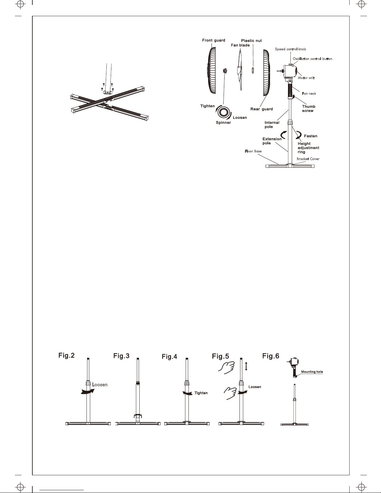
PARTS FIGURE
STAND ASSEMBLY
1. Assemble the Floor Base by fitting the upper and lower base
bars together. Remove the screws and washers from the bars. Align the holes
in the bracket at the bottom of the pole with the screw holes in the bars. Insert
the screws with washers into the holes and tighten securely. See Fig.1
2. Loosen and remove the Height adjustment ring from the top of the extension
pole. Insert the bracket cover over the top of the pole and slide the cover down
to fit over the bracket and bars. Return the Height adjustment ring to the top
of the pole. See Fig.2 and 3.
3. Loosen the Height adjustment ring at the top of the extension pole. Raise the
internal metal pole to the desired height and securely tighten the Height
adjustment ring. See Fig.4
NOTE: If the internal pole is not visible it has slipped out of sight into the
extension pole. Loosen the Height adjustment ring to slide the internal pole out.
See Fig.5.
4. To attach the motor unit to the top of the internal pole, loosen the thumb screw
at the Fan neck base. Insert the internal pole into the Fan neck base as far as it
will go. Tighten the thumb screw to secure the motor unit in place. See Fig. 6.
CAUTION: The Height adjustment ring must be tightly fastened before mounting
the motor unit to the internal pole.
Speed control knob
Motor unit
Fan neck
Floor Base
Loosen
Bracket Cover
Oscillation control button
Fig.1
2
Page 4
OPERATION
1. Speed control knob
Rotate the Speed control knob to start and stop fan and
to change fan speed to 1--Low 2--Medium 3--High.
2. Oscillation Control Button
Push down the oscillation control button on the top of the
motor unit to start fan oscillation from side to side. Raise
oscillation control button back up to stop oscillation motion.
3. Vertical Air Direction
To adjust angle of vertical air direction, grasp the sides of the guard assembly
and lightly push it either up or down.
4. Fan height adjustment
Loosen the Height adjustment ring at the top of the extension pole. Raise or
lower the internal metal pole to the desired height and securely tighten the
Height adjustment ring.
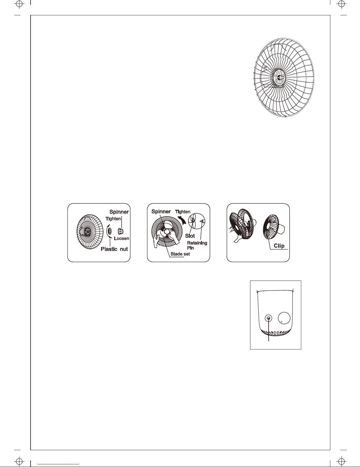
GUARD & FAN BLADE ASSEMBLY
1. Unscrew and remove the spinner clockwise (or remove
from parts bag) and the plastic nut counterclockwise.
Fig.8. Mount the rear guard against the motor face
so that the pin at the motor face bottom fits through the
tear drop hole in the rear guard mounting ring. When
correctly mounted the set of two tabs on each side of the
motor face will also fit through their designated holes in
the mounting ring, and the rear guard will rest flat and
evenly on the motor face. Fig.7.
2. Mount the Blade set onto the motor shaft through the center hole in the Blade set.
Insert the retaining pin on the motor shaft into the slots in the Blade set core. Insert
the spinner onto the tip of the shaft and turn spinner counterclockwise to secure
the Blade set in place. Fig.9.
3. Open the five latch clips on the rear guard. Align the logo on the front guard so
that it will read horizontally. Insert the edge of the front guard into the fixed clip
at the bottom of the rear guard. Use the five latch clips to secure the two guards
together. Fig.10
Fig. 7
Fig.8 Fig.9 Fig.10
Oscillation Control Button
3
0
1
2
3
Page 5
PRINTED IN CHINA
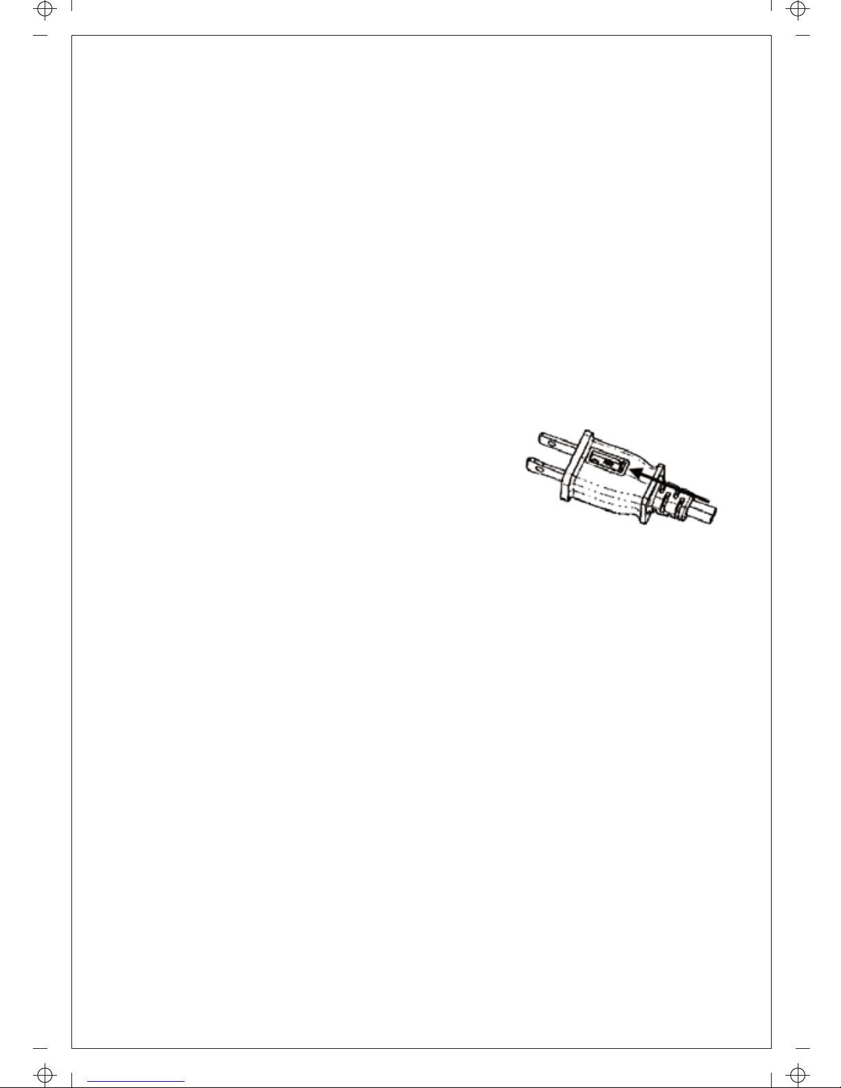
FUSE REPLACEMENT
1. Grasp the plug and remove it from the receptacle
or other outlet device. Do not unplug by pulling on
the cord.
2. Open the fuse cover. Slide open the fuse access
cover on top of power plug towards blades.
3. Remove the fuse carefully. Push the fuse from the other side or turn the fuse
holder over to remove the fuse.
WARNING: Risk of fire. Replace the fuse only with 2.5 A, 125 Volt fuse.
4. Close the fuse cover. Slide closed the fuse access cover on top of the
power plug.
WARNING: Risk of fire. Do not replace power plug. It contains a safety
device (fuse) that should not be removed. Discard product if the power plug
is damaged.
NOTICE:
1. After replacing fuse, do not at first operate at full speed. Doing so may cause
product malfunction or damage.
2. If the fan doesn't seem to operate properly after fuse replacement, check to
make sure that the fuse was inserted correctly.
CLEANING
1. Be sure to unplug fan from the electrical supply source before cleaning.
2. Clean plastic fan parts with a cloth or sponge moistened in a solution of mild
soap and water. Thoroughly remove soap film with a damp cloth. Wait for
surfaces to completely dry before running fan.
3. Be sure not to allow water or other liquid to enter the inside of the motor.
The fan requires little maintenance. Do not try to fix it by yourself. Refer it to
qualified service personnel if service is needed,or call Customer Assistance at
866-646-4332.
1. Before cleaning fan, always unplug it from the electrical outlet.
2. To ensure adequate air circulation to the motor, use a vacuum to keep vents
at the rear of the motor housing free from dust, fluff, etc. Do not disassemble
fan to remove dust or fluff.
CAUTION: To avoid injury from electrical shock, unplug the fan before using a
vacuum cleaner to clean the vents.
3. Wipe the exterior parts with a soft cloth soaking a mild detergent.
Do not use any abrasive detergent or solvents to avoid scratching the surface.
Do not use gasoline or paint thinner as a cleaner.
4. Do not allow water or any other liquid into the motor housing or interior parts.
MAINTENANCE INSTRUCTIONS
4
Page 6
SPECIFICATIONS
Model No.: FS40-8M
Voltage: 120V, 60Hz
SERVICE & SUPPORT
In the event of a warranty claim or if service is required for this fan, please
contact us at the following:
Toll Free: 866-646-4332 (M-F 9:00am to 5:00pm CST)
For questions or comments, please write to:
Midea America Corp.
Att: Warranty Department
11800 NW 100th Rd., Suite 4
Medley, FL 33178
For your records, staple your sales receipt to this manual and record the
following:
DATE OF PURCHASE: ___________________________________________
PLACE OF PURCHASE:___________________________________________
(STAPLE SALES RECEIPT HERE)
NOTE: PROOF OF PURCHASE IS REQUIRED FOR
ALL WARRANTY CLAIMS
5
Page 7

ONE(1) YEAR LIMITED WARRANTY
● Please read all instructions before attempting to use this product.
● Please return the Warranty Registration card within fifteen (15) days from the
date of purchasing this product.
Midea America Corp., referred to hereafter as Midea America, warrants as limited
herein to the original purchaser of retail that each new FS40-8M 16'' Stand Fan,
shall be free of defects in material and workmanship for a period of one (1) year
from the date of original purchase. This one (1) year warranty is limited to the fan
motor, fan blades, and electric control circuit board.
In the event of malfunctions or failure of your FS40-8M 16'' Stand Fan, simply
deliver or send the product, postage prepaid along with PROOF OF PURCHASE,
within the warranty period of one (1) year, to Midea America. Midea America
reserves the right to inspect the claimed defective part or parts to determine if the
defect or malfunction complaint is covered by this warranty. Midea America shall,
within sixty (60) days after receipt of the product, at its option, repair and/or replace
the defective part or parts free of charge. This warranty shall only cover defects
arising from normal usage.
Midea America assumes no responsibility whatsoever if the FS40-8M
16'' Stand Fan should fail during the warranty period by reasons of:
● Misuse, negligence, physical damage or accidents.
● Lack of maintenance (see cleaning).
● Repair by any unauthorized party during the warranty period.
● Damage caused by connection to an improper input voltage (see specifications).
Midea America makes no further warranties or representations, express or implied
except those contained herein. No representative or dealer is authorized to
assume any other liability regarding the FS40-8M 16'' Stand Fan.
The duration of the implied warranty granted under State law, including warranties
of merchantability and fitness for particular purpose are limited in duration should
the duration of the express warranty grant it hereunder. Midea America shall in no
event be liable for direct, indirect, special or consequential damages.
Some states do not allow limitations on how long an implied warranty lasts,
and/or the above limitations or exclusion may not apply to you. This warranty
gives you specific legal rights and you may have other rights, which vary from
state to state.
Should your FS40-8M 16'' Stand Fan fail to operate under the terms
of this limited warranty, contact Midea America at 866-646-4332
(M-F 9:00am to 5:00pm CST).
6
Page 8

SOME ASSEMBLY REQUIRED
Call Toll Free:1-866-646-4332
Page 9

Ventilador de Alta Velocidad 16"
MANUAL DE INSTRUCCIONES
Modelo:FS40-8M
LEE LAS INSTRUCCIONES Y GUÁRDALAS
Page 10

PRECAUCIÓN
Lea y siga todas las instrucciones antes de operar el ventilador. No lo utilice si
alguna pieza está dañada o pérdida.
ADVERTENCIA
1. Este aparato no está diseñado para uso por los niños pequeños o personas
enfermas sin supervisión.
2. Los niños pequeños deben ser supervisados para asegurarse de que no
jueguen con el aparato.
3. Este aparato cuenta con un enchufe polarizado (una pala más ancha que la
otra). Para reducir el riesgo de descargas eléctricas, este enchufe está
diseñado para encaje en un tomacorriente polarizado en una sola dirección.
Si el enchufe no se encaja plenamente en el tomacorriente, invierta el enchufe.
Si todavía no se encaja, contacte con un electricista calificado. No intente
omitir esta función de seguridad.
4. Si el cable de alimentación está dañado, debe ser reemplazado por el
fabricante o su agente de servicio o una persona calificada de modo
semejante, para evitar peligros.
5. Para reducir el riesgo de incendios o descargas eléctricas, no utilice este
ventilador con ningún aparato de control de velocidad de estado sólido.
6. Los cambios o modificaciones a esta unidad no expresamente aprobados por
la parte responsable de la conformidad podrían invalidar la autoridad del
usuario para operar el equipo.
REGLAS SOBRE LA SEGURIDAD DE OPERACIÓN
1. Nunca inserte los dedos, lápices, o cualquier otro objeto a través de la
carcasa cuando el ventilador está en funcionamiento.
2. Desconecte el ventilador al moverlo de un lugar a otro.
3. Desconecte el ventilador al retirar las rejillas para la limpieza.
4. No deje el ventilador en funcionamiento sin atención.
5. Asegúrese de que el ventilador se encuentre en una superficie estable y
llana cuando está en funcionamiento.
6. Las reglas sobre cables y enchufes se muestran abajo:
(1) Este producto adopta la protección (fusible) contra sobrecarga. Un fusible
fundido indica una situación de sobrecarga o cortocircuito. Si se quema el
fusible, desenchufe el producto desde el tomacorriente. Reemplace el
fusible según las instrucciones de mantenimiento para el usuario (siga lo
marcado en el producto para la especificación del fusible adecuada), y
verifique el producto. Si se funde el fusible, podría aparecer un
1
Page 11

(2) No opere ningún ventilador con un cable o enchufe dañado. Descarte el
ventilador o llame al Servicio de Atención al Cliente al 1-866-646-4332
para hacer arreglos para la posible reparación.
(3) No haga funcionar el cable bajo la alfombra. No cubra el cable con
alfombrillas, tapetes, o cubiertas similares. No tienda el cable bajo los
muebles o aparatos. Disponga el cable alejado del área de tránsito y
donde no se tropezará.
cortocircuito y debe descartar el producto o llamar al Servicio de Atención
al Cliente al 1-866-646-4332 para hacer arreglos para la posible
reparación.
2
Page 12

FIGURA DE PIEZAS
MONTAJE DEL PEDESTAL
1. Monte la Base de Suelo encajando las barras de base superior
e inferior juntas. Retire los tornillos y arandelas desde las barras. Alinee los
orificios del soporte ubicados en la parte inferior del poste con los orificios de
tornillos ubicados en las barras. Inserte los tornillos con arandelas en los orificios
y apriételos apretadamente. Vea la Figura 1.
2. Afloje y retire el Anillo de ajuste de altura desde la parte superior del poste
de extensión. Inserte la cubierta del soporte por encima de la parte superior
del poste y deslice la cubierta hacia abajo para encajar en el soporte y barras.
Recoloque el Anillo de ajuste de altura en la parte superior del poste. Vea las
Figuras 2 y 3.
3. Afloje el Anillo de ajuste de altura en la parte superior del poste de extensión.
Levante el poste interno metálico a la altura deseada y apriete el Anillo de
ajuste de altura apretadamente. Vea la Figura 4.
NOTA: Si el poste interno no es visible, se ha deslizado fuera de la vista al
poste de extensión. Afloje el Anillo de ajuste de altura para deslizar el poste
interno al exterior. Vea la Figura 5.
4. Para fijar la unidad de motor a la parte superior del poste interno, afloje el
tornillo de mariposa en la Base de cuello del ventilador. Inserte el poste interno
en la Base de cuello del ventilador en la medida de lo posible. Apriete el
tornillo de mariposa para sujetar la unidad de motor en su lugar. Vea la
Figura 6.
PRECAUCIÓN: Debe sujetar el Anillo de ajuste de altura apretadamente antes
de montar la unidad de motor en el poste interno.
Guarda frontal
Tuerca de plástico
Pala del ventilador
Guarda trasera
Perilla de control de velocidad
Botón de control
de oscilación
Unidad de motor
Cuello del
ventilador
Tornillo de
mariposa
Poste interno
Poste de extensión
Base de suelo
Sujetar
Anillo de ajuste
de altura
Cubierta del
soporte
Apretar
Aflojar
Cono de rectificación
Fig.1
3
Page 13

Fig.8 Fig.9 Fig.10
Cono de
rectificación
Cono de
rectificación
Apretar
Apretar
Clip
Conjunto de pala
Pasador de
retención
Ranura
Tuerca de plástico
Aflojar
Aflojar
Apretar
Orificio de
montaje
Aflojar
Fig. 7
MONTAJE DE LA PALA Y REJILLA
1. Desatornille y retire el cono de rectificación a derecha
(u obténgalo desde la bolsa de piezas) y la tuerca de
plástico a izquierda (Figura 8). Debería sostener el eje
en su lugar con una mano para desatornillar el cono de
rectificación con la otra mano. Monte la guarda trasera
contra la superficie del motor, para que el pasador en
la parte inferior de la superficie del motor se encaje a través
del orificio de gota en el anillo de montaje de la guarda trasera.
Una vez correctamente montado el conjunto de dos lengüetas en cada lado
de la superficie del motor, también se encajará a través de sus orificios
designados en el anillo de montaje, y la guarda trasera reposará de forma
plana y lisa sobre la superficie del motor. Vuelva a atornillar la tuerca de
plástico en la superficie del motor, para sujetar la guarda trasera en su
lugar. Figura 7
2. Monte el Conjunto de pala en el eje del motor a través del orificio central
ubicado en el conjunto de Pala. Inserte el pasador de retención ubicado en el
eje del motor en las ranuras ubicadas en el núcleo del Conjunto de pala.
Inserte el cono de rectificación en la punta del eje y gírelo a izquierda para
sujetar el Conjunto de pala en su lugar. Figura 9
3. Abra los tres clips de cierre en la guarda trasera. Alinee el logotipo en la
guarda frontal, para que será leído de forma horizontal. Inserte el borde de
la guarda frontal en el clip fijado a la parte inferior de la guarda trasera.
Utilice los tres clips de cierre para sujetar las das guardas juntas. Figura 10
4
Page 14

OPERACIÓN
1. Perilla de control de velocidad
Gire la Perilla de control de velocidad para encender y
apagar el ventilador y cambiar la velocidad del
ventilador a 1-Baja, 2-Media, 3-Alta.
2. Botón de control de oscilación
Pulse el botón de control de oscilación en la parte superior
de la unidad de motor para activar la oscilación del ventilador de lado a
lado. Libere el botón de control de oscilación para desactivar el movimiento
de oscilación.
3. Dirección del aire vertical
Para ajustar el ángulo de dirección del aire vertical, tome los lados del
conjunto de guarda y empújelo ligeramente a arriba o abajo.
4. Ajuste de altura del ventilador
Afloje el Anillo de ajuste de altura en la parte superior del poste de extensión.
Levante o baje el poste interno metálico a la altura deseada y apriete el
Anillo de ajuste de altura apretadamente.
Botón de control de oscilación
El ventilador requiere poco mantenimiento. No intente repararlo por sí mismo.
Consulte al personal de reparación calificado si es necesaria la reparación, o
llame al Servicio de Atención al Cliente al 866-646-4332.
1. Antes de limpiar el ventilador, siempre desenchúfelo desde el tomacorriente
eléctrico.
2. Para garantizar una circulación de aire adecuada para el motor, utilice una
aspiradora para proteger los conductos de ventilación en la parte trasera de
la carcasa del motor contra el polvo, pelusa, etc. No desmonte el ventilador
para eliminar el polvo o pelusa.
PRECAUCIÓN: Para evitar lesiones debido a las descargas eléctricas,
desenchufe el ventilador antes de utilizar una aspiradora para limpiar los
conductos de ventilación.
3. Limpie las partes exteriores con un paño suave humedecido en un detergente
no agresivo.
No utilice ningún detergente abrasivo o disolvente para evitar la rascadura
superficial.
No utilice ninguna gasolina o diluyente de pintura como limpiador.
4. No se permite que el agua o cualquier otro líquido entre en la carcasa del
motor o piezas interiores.
INSTRUCCIONES DE MANTENIMIENTO
5
0
1
2
3
Page 15

IMPRESO EN CHINA
REEMPLAZO DEL FUSIBLE
1. Tome el enchufe y retírelo desde el tomacorriente u
otro aparato de salida. No lo desenchufe tirando el
cable.
2. Abra la cubierta de fusibles. Deslice para abrir la cubierta
de acceso a fusibles en la parte superior del enchufe hacia las palas.
3. Retire el fusible cuidadosamente. Empuje el fusible desde el otro lado o dé
vuelta el portafusibles para retirar el fusible.
ADVERTENCIA: Riesgo de incendios. Reemplace con el fusible de 2.5A, 125
Voltios, solamente.
4. Cierre la cubierta de fusibles. Deslice para cerrar la cubierta de acceso a
fusibles en la parte superior del enchufe eléctrico.
ADVERTENCIA: Riesgo de incendios. No reemplace el enchufe eléctrico. Ésto
contiene un aparato de seguridad (fusible) que no se debe retirar. Descarte el
producto si el enchufe eléctrico está dañado.
AVISO:
1. Tras reemplazar el fusible, no opere al comienzo a plena velocidad. Si lo
hace, podría causar el mal funcionamiento o daños al producto.
2. Si parece que el ventilador no funciona adecuadamente tras el reemplazo
del fusible, verifique para asegurarse de que se inserte el fusible
correctamente.
LIMPIEZA
1. Asegúrese de desenchufar el ventilador desde la fuente de alimentación
eléctrica antes de la limpieza.
2. Limpie las piezas de plástico del ventilador con un paño o esponja
humedecido en una solución jabonosa no agresiva y agua. Elimine la
película de jabón por completo con un paño mojado. Espere a que se
sequen las superficies plenamente antes de operar el ventilador.
3. Asegúrese de no permitir que el agua o cualquier otro líquido entre en la
parte interior del motor.
6
Page 16

ESPECIFICACIONES
Modelo N. º: FS40-8M
Voltaje: 120V, 60Hz
REPARACIONES Y SOPORTE
Para reclamaciones de garantía o si necesitas reparar este ventilador, por favor
comunícate con nosotros:
Línea telefónica gratuita: 866-646-4332 (L-V 9:00am a 5:00pm, hora estándar
del centro)
Para preguntas o comentarios, escribe a:
Midea America Corp.
A: Departamento de Garantías
11800 NW 100th Rd., Suite 4
Medley, FL 33178
Para llevar un registro, engrapa tu recibo de compra a este manual y anota lo
siguiente:
FECHA DE COMPRA: ___________________________________________
LUGAR DE COMPRA:___________________________________________
(ENGRAPA EL RECIBO DE COMPRA AQUÍ)
NOTA: NECESITAS EL COMPROBANTE DE COMPRA
PARA CUALQUIER RECLAMACIÓN DE GARANTÍA
7
Page 17

GARANTÍA LIMITADA DE UN (1) AÑO
● Por favor lea todas las instrucciones antes de intentar utilizar este producto.
● Por favor envíe la tarjeta Warranty Registration (Registro de Garantía) dentro de
los quince (15) días a partir de la fecha de compra del producto.
Midea America Corp., en adelante Midea America, garantiza con las limitaciones aquí
establecidas al comprador original que ningún Ventilador de Alta Velocidad FS40-8M
de 16” presentará defectos de material ni de fabricación por el periodo de un (1) año
desde la fecha de compra original. Esta garantía de un (1) año se limita al motor del
ventilador, las aspas del ventilador y el tablero eléctrico de control.
En caso de mal funcionamiento o fallas en su Ventilador de Alta Velocidad FS40-8M
de 16”, simplemente entregue o envíe el producto con franqueo prepago junto con el
COMPROBANTE DE COMPRA, dentro del periodo de garantía de un (1) año, a
Midea America. Midea America se reserva el derecho de inspeccionar la/s parte/s
presuntamente defectuosa/s para determinar si el defecto o mal funcionamiento
están cubiertos por esta garantía. Midea America deberá, según lo estime
conveniente, reparar y/o reemplazar la/s parte/s defectuosa/s sin cargo alguno.
Esta garantía sólo cubre defectos causados por el uso normal.
Midea America no será responsable si el Ventilador de Mesa Alta Velocidad FS40-8M
de 16” se daña durante el periodo de la garantía debido a:
● Uso incorrecto, negligencia, daño físico o accidentes.
● Falta de mantenimiento (ver limpieza).
● Reparación por parte de un tercero no autorizado durante el periodo de la
garantía.
● Daño causado por conectarlo a un voltaje de alimentación incorrecto (ver
especificaciones).
Midea America no garantiza ni declara, de forma explícita o implícita, más de lo
mencionado anteriormente. Ningún representante o distribuidor está autorizado
para asumir cualquier otra responsabilidad con respecto al Ventilador de Alta
Velocidad FS40-8M de 16”. El periodo de garantía implícita otorgado por las leyes
del Estado, incluyendo las garantías de comercialización e idoneidad para un fin
específico estará limitado si la duración de la garantía expresa cubre dicho periodo.
Midea America en ningún caso será responsable por daños directos, indirectos,
especiales o secundarios.
Algunos estados no permiten limitaciones en la duración de la garantía implícita,
y/o la limitación anterior puede no aplicarse a su caso. Esta garantía le otorga
derechos legales específicos y puede gozar de otros derechos que varían de un
estado a otro.
Si su Ventilador de Mesa Alta Velocidad FS40-8M de 16” dejara de funcionar debido
a una de las causas cubiertas por esta garantía limitada, comuníquese con
Midea America al 866-646-4332 (L-V 9:00am a 5:00pm hora estándar del centro).
8
Page 18

REQUIERE ENSAMBLAJE MÍNIMO
Llama gratis al: 1-866-646-4332
 Loading...