

Midea FS40-11NR Owner's Manual
ELECTRIC FAN
GD Midea Environment Appliances MFG.CO.,Ltd.
Midea Industrial Park, Dongfu Road, Dongfeng Town, Zhongshan, Guangdong,
528425, P.R.China
OWNER’S MANUAL
16" Stand Fan
MODEL: FS40-11NR
READ AND SAVE THESE INSTRUCTIONS
Attention: Pictures in the IM are for reference only.
CAUTION
Read Rules for Safe Operation and Instructions Carefully.
WARNING
1. If the supply cord is damaged, it must be replaced by manufacturer
or its service agent or a similarly qualified person in order to avoid
a hazard.
2. To protect against the risk of electrical shock, do not immerse the
unit, cord or plug in water or other liquid.
3. This appliance can be used by children aged from 8 years and
above and persons with reduced physical, sensory or mental
capabilities or lack of experience and knowledge if they have been
given supervision or instruction concerning use of the appliance in
a safe way and understand the hazards involved. Children shall
not play with the appliance. Cleaning and user maintenance shall
not be made by children without supervision.
4. When the appliance is not in use and before cleaning, unplug the
appliance from the outlet.
5. Keep electrical appliances out of reach from Children or infirm
persons. Do not let them use the appliances without supervision.
6. When the fan was assembled, the rotor blade guard shall not be
taken off anymore
- Prior cleaning unplug the fan.
- The rotor guard shall not be dissembled/opened to clean the
rotor blades.
- Wipe the fan enclosure and rotor blade guard with a slightly
damp cloth.
RULES FOR SAFE OPERATION
1. Never insert fingers, pencils, or any other object through the grille when fan is
running.
2. Disconnect fan when moving from one location to another.
3. Be sure fan is on a stable surface when operating to avoid overturning.
4. DO NOT use fan in window, rain may create electrical hazard.
5. Household use only.
1
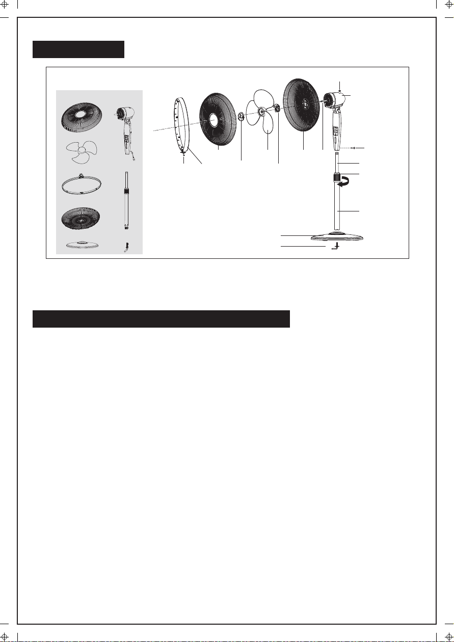
PART FIGURE
[01]x1 [06]x1
Clutch knob
Motor
housing
[02]x1
[03]x1
[04]x1
[05]x1
Front Grill
[07]x1
[08]x1
Note: All the pictures in this manual are for explanation purpose only. Any discrepancy between
the real object and the illustration in the drawing shall be subject to the real subject.
Grill
Clip
Circlip
Spinner
7-shape Bolt
Blade
Plastic Nut
Chassis
Rear Grill Motor
shaft
Thumb
screw
Internal Pole
Height
adjustment ring
Extension Pole
ASSEMBLY OF CHASSIS & COLUMN UNIT
1. Unscrew the 7-shape Bolt from the Extension Pole. (Fig.1)
2. Insert the extension pole into the chassis and tighten the 7-shape Bolt (Fig.2)
3. From the extension pole loosen the height adjustment ring and adjust the internal
pole to the desired height. (Note: If you can’t find the internal pole, it must inside
the extension pole. You can pull it out from the extension pole.) (Fig.3)
4. To attach the head unit to the internal pole, loosen the thumb screw on the bottom
of the head unit. Place the head unit on the internal pole and tighten the thumb
screw in alignment with the groove on the internal pole. (Fig.4)
CAUTION: Height adjustment ring must be fully fastened before the assembly of the
motor section to the internal pole.
2
 Loading...