

Page 1
ELECTRIC FAN
OWNER’S MANUAL
16" STAND FAN
MODEL: FS40-10AR
READ AND SAVE THESE INSTRUCTIONS
Attention: Pictures in the IM are for reference only.
GD Midea Environment Appliances MFG.CO.,Ltd.
Midea Industrial Park, Dongfu Road, Dongfeng Town, Zhongshan, Guangdong,
528425, P.R.China
Page 2
1
Read Rules for Safe Operation and Instructions Carefully.
CAUTION
1. If the supply cord is damaged, it must be replaced by manufacturer
or its service agent or a similarly qualified person in order to avoid
a hazard.
2. To protect against the risk of electrical shock, do not immerse the
unit, cord or plug in water or other liquid.
3. This appliance is not intended for use by persons (including
children) with reduced physical, sensory or mental capabilities, or
lack of experience and knowledge, unless they have been given
supervision or instruction concerning use of the appliance by a
person responsible for their safety. Young children should be
supervised to ensure that they do not play with the appliance.
4. When the appliance is not in use and before cleaning, unplug the
appliance from the outlet.
5. Keep electrical appliances out of reach from Children or infirm
persons. Do not let them use the appliances without supervision.
6. When the fan was assembled, the rotor blade guard shall not be
taken off anymore
- Prior cleaning unplug the fan.
- The rotor guard shall not be dissembled/opened to clean the
rotor blades.
- Wipe the fan enclosure and rotor blade guard with a slightly
damp cloth.
WARNING
1. Never insert fingers, pencils, or any other object through the grille when fan is
running.
2. Disconnect fan when moving from one location to another.
3. Be sure fan is on a stable surface when operating to avoid overturning.
4. DO NOT use fan in window, rain may create electrical hazard.
5. Household use only.
RULES FOR SAFE OPERATION
Page 3
2
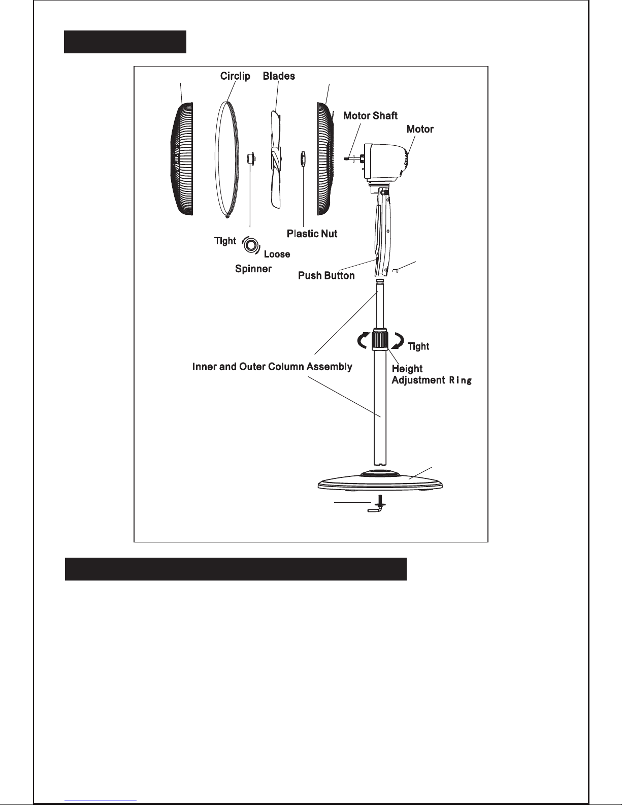
PART FIGURE
1. Unscrew the 7-shape Bolt from the Extension Pole. (Fig.1)
2. Insert the extension pole into the chassis and tighten the 7-shape Bolt (Fig.2)
3. From the extension pole loosen the height adjustment ring and adjust the internal
pole to the desired height. (Note: If you can’t find the internal pole, it must inside
the extension pole. You can pull it out from the extension pole.) (Fig.3)
4. To attach the head unit to the internal pole, loosen the thumb screw on the bottom
of the head unit. Place the head unit on the internal pole and tighten the thumb
screw in alignment with the groove on the internal pole. (Fig.4)
CAUTION: Height adjustment ring must be fully fastened before the assembly of the
motor section to the internal pole.
ASSEMBLY OF CHASSIS & COLUMN UNIT
7-shape Bolt
Note: All the pictures in this manual are for explanation purpose only. Any discrepancy between
the real object and the illustration in the drawing shall be subject to the real subject.
Thumb screw
Chassis
Rear grillFront grill
Page 4

3
GRILL & FAN BLADE ASSEMBLY
Annular groove
Mounting hole
Thumb screw
F
ig.3
Loo
seen
F
ig.4
Fig.1
Fig.2
1. Unscrew the spinner clockwise (or take the spinner out from the bag) and the
plastic nut counterclockwise to remove both of them. Fix the rear grill to the
motor then tighten the plastic nut again. (Fig.5)
2. Insert the blade into shaft, and make sure the rotor shaft pin is fitted into groove
of the blade. Turn the spinner counterclockwise to tighten the blade. (Fig.6)
3. Fix the front grill and the rear grill with circlip clip and then fasten the circlip clip
and lock the screw and nut. (Fig.7)
Fig.5 Fig.6 Fig.7
Page 5

4
OPERATING INSTRUCTION
I. Remote Controller (Fig.8)
a. KEY INSTRUCTION
1. “ ” ON/OFF KEY
The “ ” key is for switching on the fan .The fan will be
started at breeze step.
Press the “ ” key if the fan needs to switch off.
2. “ ” SPEED KEY
When the fan started, press this key repeated, the fan will
work with “1-2-3-4-5-6” circulatory.
3. “ ” MODE KEY
Press this key to select mode. The sequence is normal, natural and sleep when this
key being touched repeatedly or continuously. The light can indicate mode state.
Normal wind
Press the “mode” key to select the normal wind, then press the “speed” repeatedly
to choose 8 speed.
Natural wind
Press the “mode” key to select the natural wind, then press the “speed” repeatedly
to choose 3 speed.
Sleep wind
Press the “mode” key to select the sleep wind, then press the “speed” repeatedly
to choose 2 speed.
4. “ ” OSC/LOUVER KEY
After the fan has started, press this key to select oscillation mode. The sequence is
wiggly, fluctuating, eight-rock and fixedly. The lights on the display can indicate fan
oscillation mode.
5. “ ” TIMING KEY
When the fan is in the stand by mode after the power line is plugged in, press the
key to switch the fan to the appointment mode. When this key is pressed repeatedly,
appointment time will be subject to the cyclic change in the order of “0.5h-1h-...-7h-
7.5h-0h-0.5h...”. Meanwhile, corresponding indicators will be on. Time indicator will
extinguish in turn as the time pass by.
When the appointment time is over, the fan will automatically work at the normal air
mode with the level 1 speed.
When the fan is working, press this key to preset the time of turning off. When this
key is pressed repeatedly, the time will be subject to the cyclic change in the order
Fig.8
Page 6

5
of “0.5h-1h-...-7h-7.5h-0h-0.5h...”. Meanwhile, corresponding indicator will be on.
Time indicators will extinguish in turn as the time pass by.
When the preset time is over, the fan will be switched off automatically.
6. “ ” SILENCE KEY
In the state of non-silence, press silence button, the fan would be in silent state and
the silence icon is lightened, while the indicator icons of the other wind types and
wind levels would turn off. In silent state, press wind type button, blast volume + and
– buttons, there would be no response, while other buttons could respond normally.
Press silence button again to quit and the fan would return to the previous working
state. The silence icon turns off and 00 is displayed on the digital screen.
b. BATTERIES
(battery not included in the packing)
(1) Slide the battery compartment Cover.
(2) Insert the batteries, and make sure that the
batteries are placed as shown in the Fig.9.
(3) Slide back the battery cover.
NOTES: Use size “AAA” manganese or alkaline
batteries. Do not use rechargeable batteries.
c. BATTERY WARNING AS BELOW
1. “Do not dispose of batteries in fire, batteries may
explode or leak.”
2. -Do not mix old and new batteries.
3. -Do not mix alkaline, standard (carbon-zinc) or
rechargeable (nickel-cadmium) batteries.
d. REMOTE CONTROLLER OPERATION
Point the remote controller at the receptor on body of the fan and press the desired
button. The remote controller will work at distances of up to roughly five meters and
the angle of 30 degree included between right and left from the receptor.
The batteries must be removed from the remote controller before it is scrapped and
that they are disposed of safely.
e. OVERHEAT PROTECTION OF THE MOTOR
The windings of the motor have a thermal-fuse that burns out and the fan switches
off and temperature of the motor is no longer going up so that plastic parts of the fan
don’t subject to deformation so far so to be burned by the overheat if the motor is
overheat for any unexpected reason.
Fig.9
Page 7

6
II. Buttons on fan body (Fig.10) / Panel indication (Fig.11)
The buttons on the body such as air speed, on/off, air mode, mute, appointment/
timer, oscillation have the same functions as those of the corresponding keys on the
remote controller.
III. Height adjustment
Turn the outer joint to adjust the inner/outer upright post tube to the proper height,
and then tighten the outer joint. (Fig.3)
IV. Pitching air supply
When adjusting the upward or downward air supply of the fan, it is allowed to slightly
lift or press the nose or grill for adjustment.
The fan requires little maintenance. Do not try to fix it by yourself. Refer it to qualified
service personnel if service is needed.
1. Before cleaning and assembling, fan must be unplugged.
2. To ensure adequate air circulation to the motor, keep vents at the rear of the
motor free of dust. Do not disassemble the fan to remove dust.
3. Please wipe the exterior parts with a soft cloth soaking a mild detergent.
4. Do not use any abrasive detergent or solvents to avoid scratching the surface.
Do not use any of the following as a cleaner: gasoline, thinner.
5. Do not allow water or any other liquid into the motor housing or interior parts.
MAINTENANCE INSTRUCTION
CLEANING
1. Be sure to unplug from the electrical supply source before cleaning.
2. Plastic parts should be cleaned with a soft cloth moisten with mild soap.
Thoroughly remove soap film with dry cloth.
Fig.10
Fig.11
 Loading...