

Page 1
1.FEATURE
2.FUNCTIONS
3.Accessories(packedwithoutdoorunit)
DR CONTROL BOX
Installation Instructions for MIDEA FMVDR series
Before you s ta rt
Read and understand this manual before operating this equipment. The manual should be kept for future reference along with the product supplied.
Improper installation or handling will cause leakage, electric shock, or fire.
DR control box is only to be installed by a qualified person who is familiar with the installation, construction, operation or maintenance of the
equipment and the hazards involved. In addition this person is competent, trained and authorized to undertake the work involved in accordance with
established safety and working procedures.
Do not turn on the power before all work has been completed. Otherwise it may cause serious accidents such as electric shock or fire.
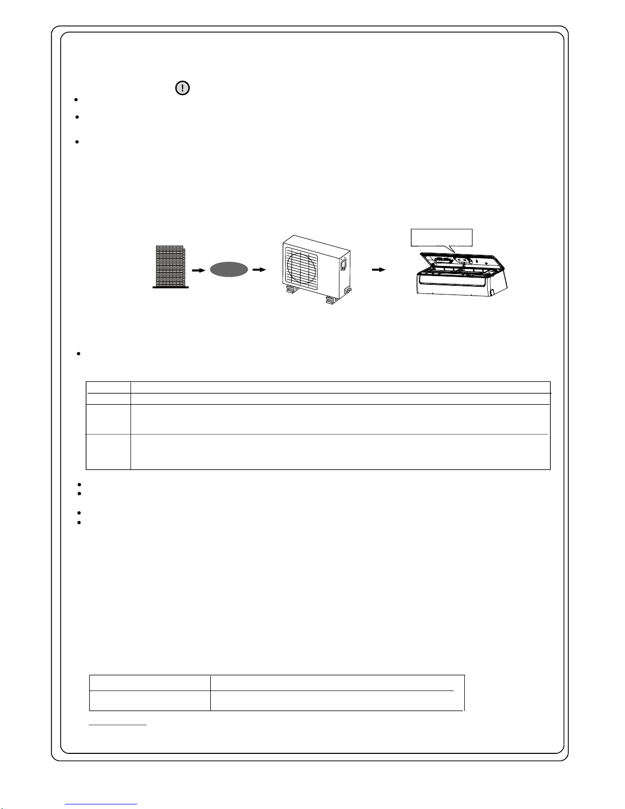
This product is designed to be compatible with an air conditioning demand response program. The DR control box connected with your air conditioner and the
Demand Control Signal Receiver (DCSR) which is field supplied needs to be installed in your air conditioning system. A separate arrangement with the energy provider to
access the Demand Response feature must be made.
The power consumption of the compressor will be reduced after receipt of the signal from the energy provider if the DR control box is fitted to the pre configured air conditioner.
DemandResponseFlow:
DCSR
DRCONTROLBOX
Energyprovider
Energysaving
Fig.1
DRmode
DRmode1 Compressoroff.
TheairconditionercontinuestocoolorheatduringtheDemandResponseevent,buttheelectricalenergyconsumed
bytheairconditionerinahalfhourperiodisnotmorethan50%ofthetotalelectricalenergythatwouldbeconsumedif
operatingattheratedcapacityinahalfhourperiod.
TheairconditionercontinuestocoolorheatduringtheDemandResponseevent,buttheelectricalenergyconsumed
bytheairconditionerinahalfhourperiodisnotmorethan75%ofthetotalelectricalenergythatwouldbeconsumedif
operatingattheratedcapacityinahalfhourperiod.
DRmode2
DRmode3
Descriptionofoperationinthismode
,,
During the operation of the unit, if the DR control box receives the signals via the mains input from the DCSR, it will send signals of
DR1,DR2 or DR3 to the indoor unit. The indoor unit display area will display d1, d2 or d3. The DR information(including DR malfunction)
cannot be displayed when the unit is off or under abnormal condition, self clean operation, or LED display feature is activated.
DRConnectivewireA
DRConnectivewireB
Connecting the indoor unit & outdoor unit (Length: 9m)
Connection to DR terminal board of outdoor unit(Length:250mm)
IMPORTANT:
During connection, no wires should be allowed to touch refrigerant tubing, the compressor or any high voltage
parts. DR connective wires A& B should be fixed with band to ensure they are firmly connected.
When a DR signal input malfunction occurs, the display area of indoor unit will display "dE" and the unit will operate without DR mode.
Initiating a forced cool operation under DR mode, or going into DR mode under forced cool operation are both valid.
Whilst in DR mode and operation
on forced cool mode for half an hour, the unit will go into Auto mode with a SET temperature of 24OC.
DR mode is not valid under Self Clean operation but activating Self Clean feature using the remote controller is valid whilst in DR mode.
When the unit goes into a DR mode, it performs moderate operation though the cooling or heating effect may be reduced.
NOTE : The DR control box is specially designed with ON/OFF function and Switch function controll
ed ext
ernally.
Multiple units
can be controlled simultaneous
ly. A magnetic ring should be used if the connective cable is t
oo long.
Maximum length of the connective cable is not to exceed 100 meters from the external control switch to the end wire.
ON/OFF function: When the external control switch is opened, the indoor unit will go into Auto mode with the setting
temperature of 24 C. When the external control switch is closed, the indoor unit turns off automatically. The remote
controller is enabled regardless of ON or OFF state of the indoor unit . No prioritized operation between the remote
controller and the external control switch
SWITCH function: The interfaces of SWITCH 1 and SWITCH 2 have been connected by placing a jumper cap on
CN42 position(see wiring diagram on next page)in the factory. If connecting to the external control switch, make sure
to remove the jumper cap on CN42 first. When the external control switch is closed, the indoor unit is adjustable and
the remote controller is enabled. When the external control switch is opened, the indoor unit is forced shutdown,
the display area of indoor unit will display "CP" and the remote controller is disabled.
Page 2
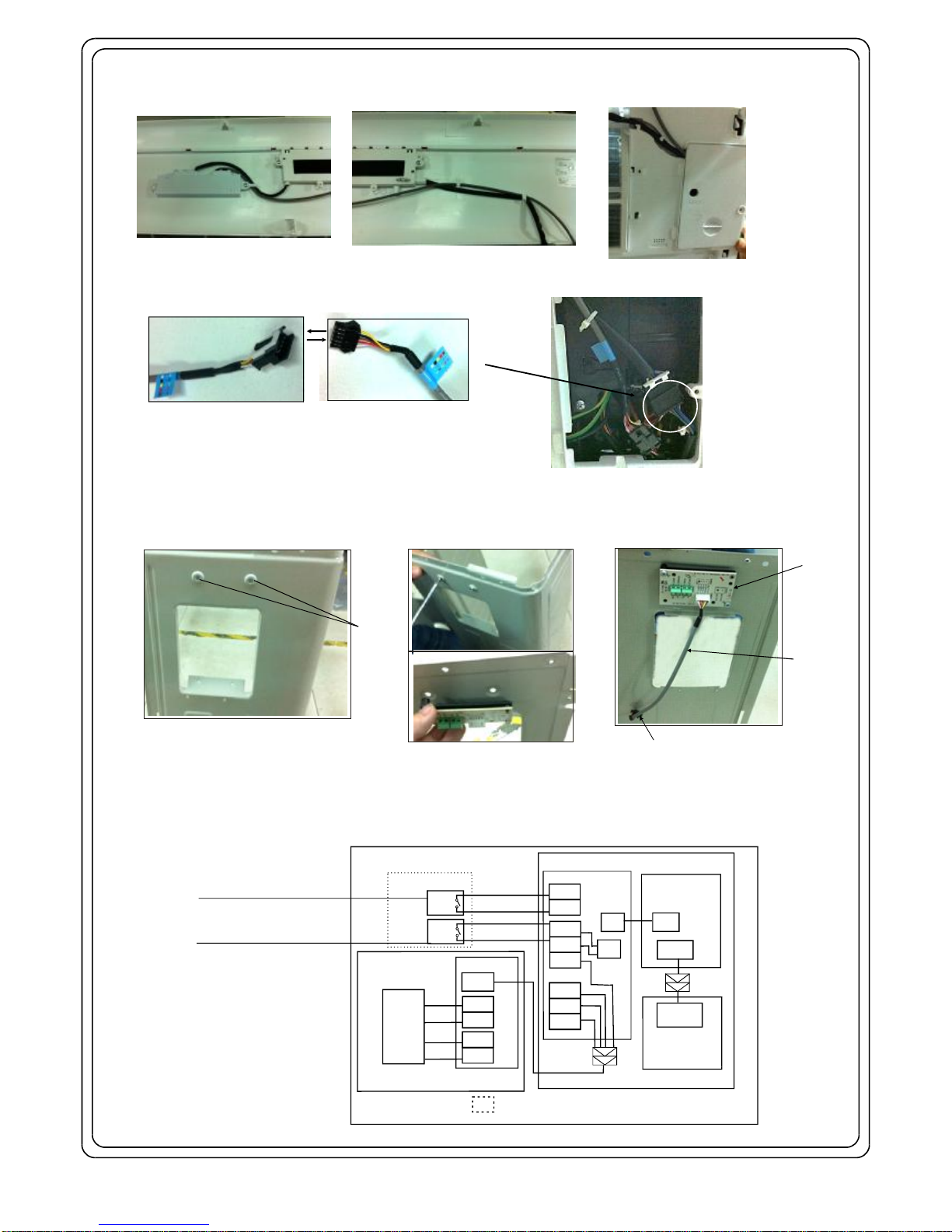
4.WIRECONNECTIONOFINDOORUNITANDOUTDOORUNIT
WARNING:Beforeperforminganyelectricalwork,unplugtheunitandturnoffthemainpowertothesystem
1.TheDRcontrolboxhasbeeninstalledandconnectedwiththeindoorunitasshowninFig.2.
2.Remove cover of the electrical control box of indoor unit by loosening the screw. Inside there is a connector which can be connected with the
DR connective wire A(9m) , as shown in Fig.3.
3.The outdoor DR board is installed at the back of the right-side plate of outdoor unit, fixed by two screws as shown in Fig. 4 (the DR board is installed on
the plate horizontally or vertically (model dependent). First remove the top cover and then take down the DR board by loosening the screws from outside
of the outdoor unit. Using the DR connective wire B(250mm), connect to the DR board with the DR connective cable A(9m). Then connect the DR board
with DCSR as shown in Fig.5. After connection, reinstall the DR board on the right-side plate with the original two screws.
Fig.2
Fig.3
Fig.4
Fig.5
Connectorofindoorunit
Screws
DRboard
DRconnective
wireB
(250mm)
Right-sideplateofoutdoorunit
(frontview)
Loosenthescrewsandtakethe
DRboarddown(backview)
ConnecttotheDRconnective
cable A(9m)
ConnectorofDR
connectivewireA(9m)
Operationstate:
Open:IndoorunitON
Close:IndoorunitOFF
Operationstate:
Open:Indoorunitforced OFF
Close:IndoorunitON
NOTE:Thissymbolindicatestheelementisoptional,theactualshapeshallprevail.
OUTDOORUNITDRBOARD
ON/OFF1
DRM3
DRM2
DRM1
COMMON
Government
A/CController
(DCSR)
PURPLE
PINK
GRAY
ORANGE
ON/OFF2
SWITCH2
SWITCH1
MAINBOARD
USER
SWITCH
USER
SWITCH
INDOORUNIT
CN4
CN3
CN2
OPTIONAL
DISPLAYBOARD
CN301
CN201
CN201
CN42
Government
A/CController
(DCSR)
DRM3
DRM2
DRM1
OUTDOORUNIT
DRM3
DRM2
DRM1
DRM3
DRM2
DRM1
CN904
COMMON
CN903
CN902
YELLOW
WHITE
RED
BROWN
DRBOARD
CN5OR
CN10ORCN10A
4. Wiring diagram of indoor unit and outdoor unit, Fig5. For more details, please refer to the Installer's Manual of the Demand Control
Signal Receiver supplied by Electric Power Company..
Page 3

1.FEATURE
2.FUNCTIONS
DR CONTROL BOX
Installation Instructions for MIDEA DMORCDR, MIS splits & MM series Multi's
Before you sta rt
Read and understand this manual before operating this equipment. The manual should be kept for future reference along with the product supplied.
Improper installation or handling will cause leakage, electric shock, or fire.
DR control box is only to be installed by a qualified person who is familiar with the installation, construction, operation or maintenance of the
equipment and the hazards involved. In addition this person is competent, trained and authorized to undertake the work involved in accordance
with established safety and working procedures.
Do not turn on the power before all work has been completed. Otherwise it may cause serious accidents such as electric shock or fire.
This product is designed to be compatible with an air conditioning demand response program. The DR control box connected with your air conditioner and the
Demand Control Signal Receiver (DCSR) which is field supplied needs to be installed in your air conditioning system. A separate arrangement with the energy provider to
access the Demand Response feature must be made.
The power consumption of the compressor will be reduced after receipt of the signal from the energy provider if the DR control box is fitted to the pre configured air conditioner.
DemandResponseFlow:
DCSR
DRCONTROLBOX
Energyprovider
Energysaving
Fig.1
DRmode
DRmode1 Compressoroff.
TheairconditionercontinuestocoolorheatduringtheDemandResponseevent,buttheelectricalenergyconsumed
bytheairconditionerinahalfhourperiodisnotmorethan50%ofthetotalelectricalenergythatwouldbeconsumedif
operatingattheratedcapacityinahalfhourperiod.
TheairconditionercontinuestocoolorheatduringtheDemandResponseevent,buttheelectricalenergyconsumed
bytheairconditionerinahalfhourperiodisnotmorethan75%ofthetotalelectricalenergythatwouldbeconsumedif
operatingattheratedcapacityinahalfhourperiod.
DRmode2
DRmode3
Descriptionofoperationinthismode
,,
During the operation of the unit, if the DR control box receives the signals via the mains input from the DCSR, it will send signals of
DR1,DR2 or DR3 to the indoor unit. The indoor unit display area will display d1, d2 or d3. The DR information(including DR malfunction)
cannot be displayed when the unit is off or under abnormal condition, self clean operation, or LED display feature is activated.
When a DR signal input malfunction occurs, the display area of indoor unit will display "dE" and the unit will operate without DR mode.
Initiating a forced cool operation under DR mode, or going into DR mode under forced cool operation are both valid.
Whilst in DR mode and operation on forced cool mode for half an hour, the unit will go into Auto mode with a SET temperature of 24OC.
DR mode is not valid under Self Clean operation but activating Self Clean feature using the remote controller is valid whilst in DR mode.
When the unit goes into a DR mode, it performs moderate operation though the cooling or heating effect may be reduced.
Page 4

1.Firstremovethetoppanel.2.Thenremovetheshield
paneltofindtheDRboard.
Firstremovehandlecover.
Plug-inco
nnector
Inserttheconnectoralltheway.
ModelA
ModelC
ModelB
Forsomemodels,toconnect
theDRboard,justremovethe
toppanel.
Government
A/CController
(DCSR)
CN2
CN3
CN1
ConnectthecablewithDRboard
3. WIRE CONNECTION TO DR BOARD
WARNING: Before performing any electrical work, unplug the unit and turn off the main power to the system.
During connection, no wire should be allowed to touch refrigerant tubing, the compressor or any high
voltage parts.
1. Remove the top panel and shield panel from the outdoor unit.
2. Connect the DR board to the Demand Control Signal Receiver(DCSR
) which is field suppled, according to the colour of the wires.
3. Please see the wiring diagrams as shown below. For more details, please refer to the Installer's Manual of the Demand Control
Signal Receiver supplied by Electric Power Company..
 Loading...