

Page 1

Portable Air Conditioner
(Local Air Conditioner)
Instruction Manual
SOGNIDORO-09E
SOGNIDORO-12E
MPPFB-09CRN7
Thank you for purchasing our Portable Air Conditioner.
Before using your air conditioner, please read this instruction manual carefully and keep it for future reference.
READ AND SAVE THESE INSTRUCTIONS!
Page 2

Contents
Preparation
Safety Precautions
Cautions
Warning
Installation
Operation
Maintenance
Faults Diagnosis
Design and Compliance Notes
Sociable Remark
Other tips
-----------------------------------------
------------------------------------------
--------------------------------------
------------------------------
--------------------------------------
----------------------------------------
-------------------------------------
---------------------------------
---------------------------------
----------------------------------------
--------------------
2
4
5
6
7
11
17
18
19
20
21
Page 3
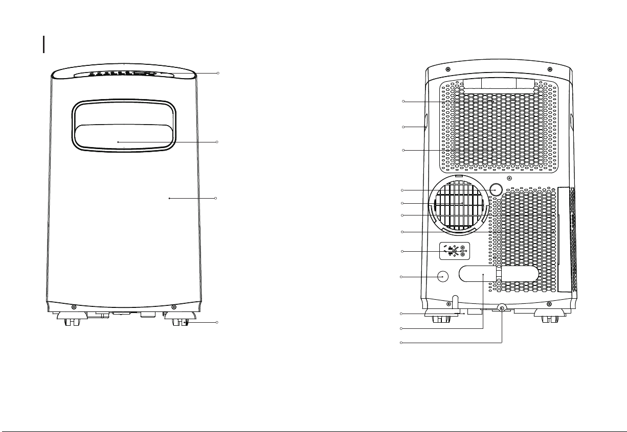
Preparation
control panel
horizontal louver
blade
upper air filter
(behind the grille)
handle
(both sides)
upper air intake
Panel
Caster
drain outlet
air outlet
lower air filter
lower air intake
power plug socket
drain outlet
(only for pump
heating mode)
power cord outlet
power cord buckle
bottom tray
drain outlet
2
rearfront
Page 4
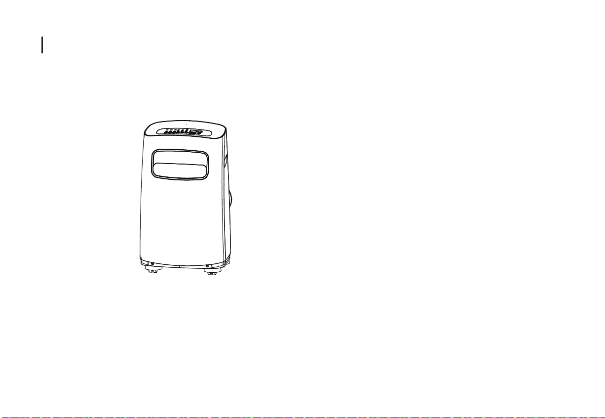
Preparation
NOTE: The unit you purchased may be look like one of the following(s):
3
Page 5
Safety Precautions
This symbol indicates that ignoring instructions may cause death or serious injury.
WARNING: To prevent death or injury to the user or other people and property damage, the following instructions
must be followed. Incorrect operation due to ignoring of instructions may cause death, harm or damage.
-Installation must be performed according to the installation
instructions. Improper installation can cause water leakage,
electrical shock, or fire.
-Use only the included accessories and parts, and specified
tools for the installation. Using non-standard parts can
cause water leakage, electrical shock, fire, and injury or
property damage.
-Make sure that the outlet you are using is grounded and
has the appropriate voltage. The power cord is equipped
with a three-prong grounding plug to protect against shock.
Voltage information can be found on the side of the unit,
behind the grille.
-Install the unit on a flat, sturdy surface. Failure to do so
could result in damage or excessive noise and vibration.
-The unit must be kept free from obstruction to ensure
proper function and to mitigate safety hazards.
-DO NOT modify the length of the power cord or use an
extension cord to power the unit. DO NOT share a single
outlet with other electrical appliances. Improper power
supply can cause fire or electrical shock.
-Turn off the product when not in use.
-DO NOT install your air conditioner in a wet room such as
a bathroom or laundry room. Too much exposure to water
can cause electrical components to short circuit.
-DO NOT install the unit in a location that may be exposed
to combustible gas, as this could cause fire.
-The unit has wheels to facilitate moving. Make sure not to
use the wheels on thick carpet or to roll over objects, as
these could cause tipping.
-DO NOT operate a unit that it has been dropped or damaged.
-The appliance with electric heater shall have at least 1 meter
space to the combustible materials.
-Do not touch the unit with wet or damp hands or when barefoot.
-DO NOT allow children to play with the air conditioner.
Children must be supervised around the unit at all times.
-If the air conditioner is knocked over during use, turn off the
unit and unplug it from the main power supply immediately.
Visually inspect the unit to ensure there is no damage. If you
suspect the unit has been damaged, contact a technician or
customer service for assistance.
-In a thunderstorm, the power must be cut off to avoid damage
to the machine due to lightning.
4
Page 6
Cautions
Cautions
-This appliance can be used by children aged from 8 years and above and person with reduced physical, sensory or
mental capabilities or lack of experience and knowledge if they have been given supervision or instruction concerning
use of the appliance in a safe way and understand the hazards involved. Children shall not play the appliance. Cleaning
and user maintenance shall not be made by children without supervision. (be applicable for the European Countries)
-This appliance is not intended for use by persons (including childern) with reduced physical, sensory or mental
capabilities or lack of experience and knowledge, unless they have been given supervision or instruction concerning
use of the appliance by a person responsible for their safety. (be applicable for other countries except the European
Countries )
-Children should be supervised to ensure that they do not play with the appliance.
-If the supply cord is damaged, it must be replaced by the manufacturer,its service agent or similarly qualified persons
in order to avoid a hazard.
-Prior to cleaning or other maintenance, the appliance must be disconnected from the supply mains.
-Do not remove any fixed covers. Never use this appliance if it is not working properly, or if it has been dropped or damaged.
-Do not run cord under carpeting. Do not cover cord with throw rugs, runners, or similar coverings. Do not route cord
under furniture or appliances. Arrange cord away from traffic area and where it will not be tripped over.
-Do not operate unit with a damaged cord, plug, power fuse or circuit breaker. Discard unit or return to an authorized service
facility for examination and/or repair.
-To reduce the risk of fire or electric shock, do not use this fan with any solid-state speed control device.
-The appliance shall be installed in accordance with national wiring regulations.
-Contact the authorised service technician for repair or maintenance of this unit.
-
Contact the authorised installer for installation of this unit.
-Do not cover or obstruct the inlet or outlet grilles.
-Do not use this product for functions other than those described in this instruction manual.
-
Before cleaning, turn off the power and unplug the unit.
-
Disconnect the power if strange sounds, smell, or smoke comes from it.
5
Page 7
Warning
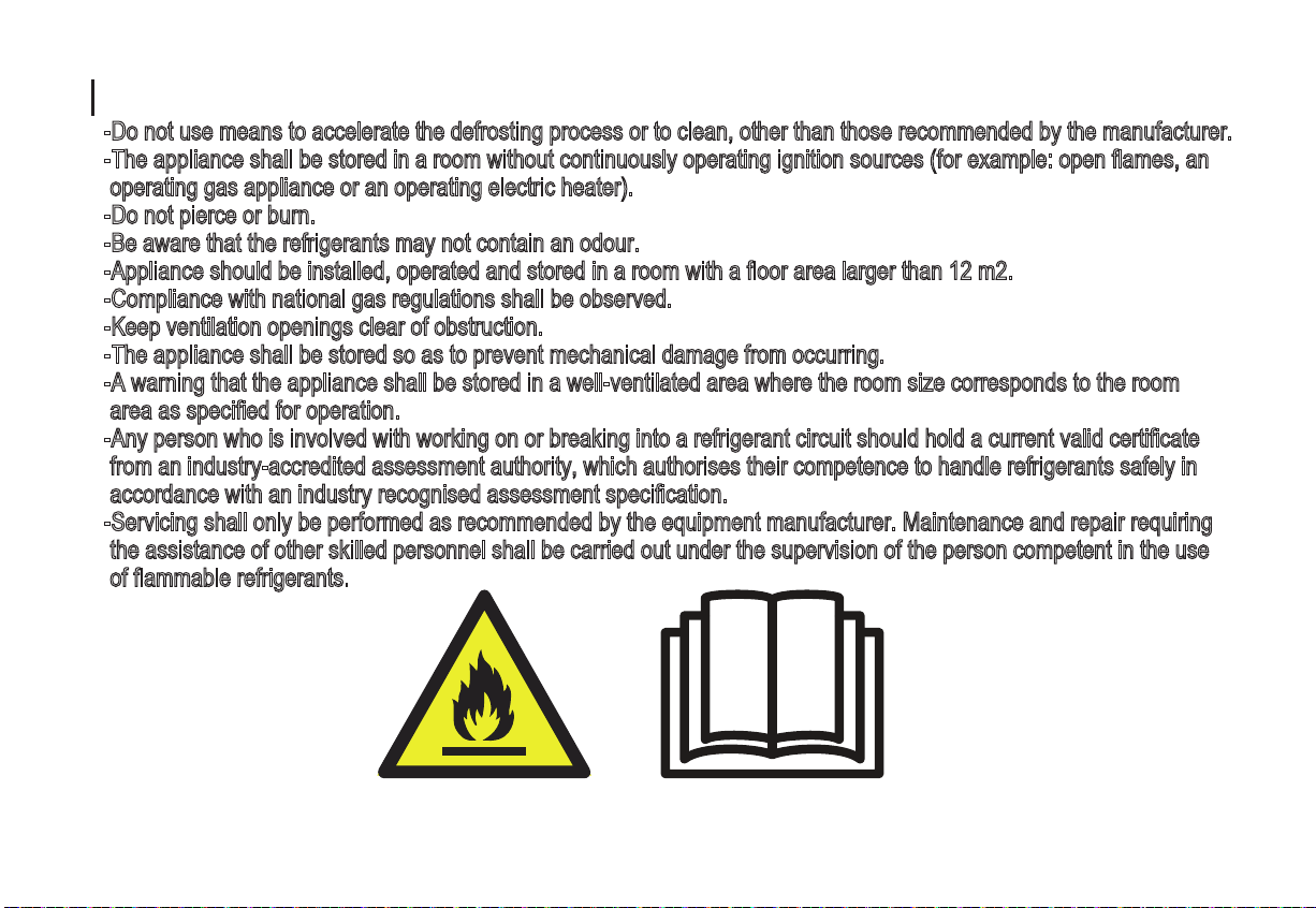
-Do not use means to accelerate the defrosting process or to clean, other than those recommended by the manufacturer.
-The appliance shall be stored in a room without continuously operating ignition sources (for example: open flames, an
operating gas appliance or an operating electric heater).
-Do not pierce or burn.
-Be aware that the refrigerants may not contain an odour.
-Appliance should be installed, operated and stored in a room with a floor area larger than 12 m2.
-Compliance with national gas regulations shall be observed.
-Keep ventilation openings clear of obstruction.
-The appliance shall be stored so as to prevent mechanical damage from occurring.
-A warning that the appliance shall be stored in a well-ventilated area where the room size corresponds to the room
area as specified for operation.
-Any person who is involved with working on or breaking into a refrigerant circuit should hold a current valid certificate
from an industry-accredited assessment authority, which authorises their competence to handle refrigerants safely in
accordance with an industry recognised assessment specification.
-Servicing shall only be performed as recommended by the equipment manufacturer. Maintenance and repair requiring
the assistance of other skilled personnel shall be carried out under the supervision of the person competent in the use
of flammable refrigerants.
6
Page 8
Installation
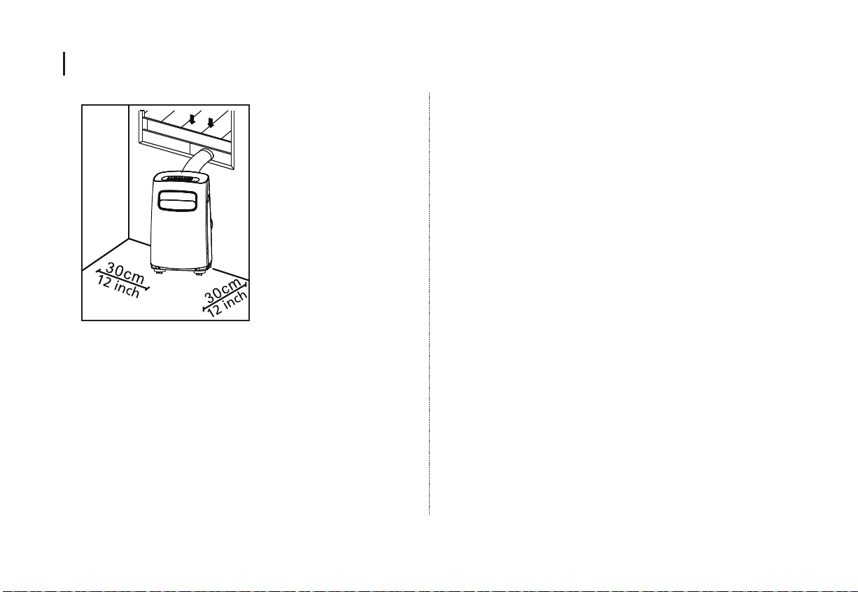
Choosing The Right Location
Your installation location should meet the following
requirements:
-Make sure that you install your unit on an even surface to
minimize noise and vibration.
-The unit must be installed near a grounded plug, and the
Collection Tray Drain (found on the back of the unit) must
be accessible.
-The unit should be located at least 30cm (12”) from the
nearest wall to ensure proper air conditioning.
-DO NOT cover the Intakes, Outlets or Remote Signal
Receptor of the unit, as this could cause damage to the
unit.
NOTE:
All the illustrations in the manual are for explanation
purpose only. Your machine may be slightly different.
The actual shape shall prevail.
The unit can be controlled by the unit control panel
alone or with the remote controller. This manual does
not include Remote Controller Operations, see the
<<Remote Controller Instruction>> packed with the
unit for details.
7
Page 9

Installation
Tools Needed
-Medium Philips screwdriver; -Tape measure or ruler; -Knife
or scissors; -Saw (optional, to shorten window adaptor for
narrow windows)
Accessories
Your Window Installation Kit fits windows 67.5-123cm
(26.5-48”) and can be shortened for smaller windows.
Part Description
Unit Adaptor
Exhaust Hose
*
*
*
*
*
Window Slider Adaptor
Wall Exhaust Adaptor A (only for wall installation)
Wall Exhaust Adaptor B(with cap)(only for wall installation)
Bolt
Window Slider A(with hole),
Window Slider B
Screw and anchor (only for wall installation)
Foam Seal A (Adhesive)
*
Foam Seal B (Adhesive)
*
Foam Seal C (Non-adhesive)
*
Security Bracket and 2 Screws
*
Drain Hose,
Power Cord Buckle
Drain Hose Adaptor(only for heat pump mode)
LED
TIMER
ON
TIMER
OFF
SHORT
CUT
TEMP
SWING
FAN
MODE
SLEEP
ON/OFF
Items with are optional. Slight variations in design may occur.
*
Remote Controller and Battery
(For remote control models only)
Quantity
1 pc
1 pc
1 pc
1 pc
1 pc
1 pc
1 set
4 set
2 pc
2 pc
1 pc
1 set
1 set
1 pc
1 set
8
Window Installation Kit(optional)
Step One: Preparing the Exhaust Hose assembly
Press the exhaust hose into the window slider adaptor (into wall
window slider adaptor for wall installation) and unit adaptor,
clamp automatically by elastic buckles of the adaptors.
Exhaust hose
Unit adaptor
Exhaust hose assembly
Window slider adaptor
Type window installation
Exhaust hose
Unit adaptor
Type wall window installation
Exhaust hose assembly
Wall exhaust adaptor A
Step Two: Install the Exhaust hose assembly to the unit
Insert unit adaptor of the Exhaust hose assembly into the lower
groove of the air outlet of the unit while the hook of the adaptor
is aligned with the hole seat of the air outlet and slide down the
Exhaust hose assembly along the arrow direction for installation.
Hook
adaptor
Hole Seat
Lower groove
Make sure the adaptor is inserted into the
lower groove of the air outlet.
Step Three: Preparing the Adjustable Window Slider
1. Depending on the size of your window, adjust the size
of the window slider.
2. If the length of the window requires two window sliders,
use the bolt to fasten the window sliders once they are
adjusted to the proper length.
Window slider A Window slider B
Bolt
Page 10

Installation
Note: Once the Exhaust Hose assembly and Adjustable Window Slider
are prepared, choose from one of the following three installation methods.
Type 1: Hung Window Installation(optional)
Foam seal B
(Adhesive type-shorter)
Window slider B
Window slider A
(if required)
Foam seal A
(Adhesive type)
Insert the window slider adaptor
into the hole of the window slider.
Cut the adhesive foam seal A
and B strips to the proper
lengths, and attach them to
the window sash and frame
as shown.
Foam seal C
(Non-adhesive type)
2 Screws
Cut the non-adhesive foam
seal C strip to match the width
of the window. Insert the seal
between the glass and the
window frame to prevent air
and insects from getting into
the room.
Insert the window slider
assembly into the window
opening.
Security Bracket
Type 2: Sliding Window Installation(optional)
If desired, install the security
bracket with 2 screws as shown.
9
Foam seal B
(Adhesive type-shorter)
Foam seal A
(Adhesive type)
Cut the adhesive foam seal A
and B strips to the proper
lengths, and attach them to
the window sash and frame
as shown.
Window slider B
(if required)
Window slider A
Insert the window slider
assembly into the window
opening.
Page 11
Installation
Expansion anchor
Foam seal C
(Non-adhesive type)
Cut the non-adhesive foam
seal C strip to match the
window height. Insert the foam
seal between the glass and the
window frame to prevent air
and insects from getting into
the room.
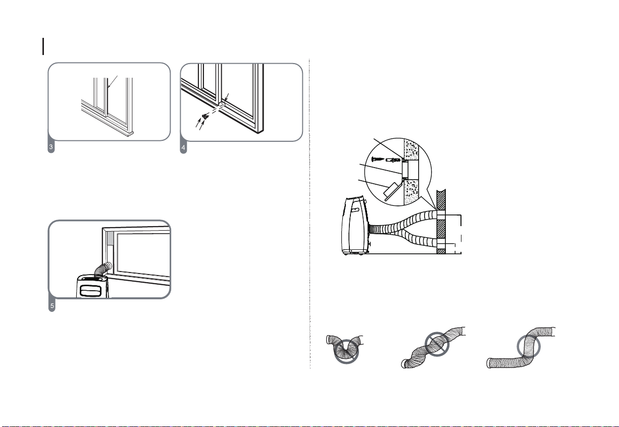
Type 3: Wall Installation(optional)
Security
Bracket
-Cut a 125mm (4.9inch) hole into the wall for the Wall Exhaust Adaptor B.
-Secure the Wall Exhaust Adaptor B to the wall using the four Anchors
and Screws provided in the kit.
-Connect the Exhaust Hose Assembly(with Wall Exhaust Adaptor A) to the
2 Screws
Wall Exhaust Adaptor B.
If desired, install the security
bracket with 2 screws as shown.
Wall Exhaust
Adaptor B
Adaptor cap
position
Note: Cover the hole using the
adaptor cap when not in use.
max 120cm or 47 inch
Insert the window slider adaptor
into the hole of the window slider.
min 30cm or 12 inch
Note: To ensure proper function, DO NOT overextend or bend
the hose. Make sure that there is no obstacle around the air
outlet of the exhaust hose (in the range of 500mm) in order to
the exhaust system works properly. All the illustrations in this
manual are for explanation purpose only. Your air conditioner
may be slightly different. The actual shape shall prevail.
10
Page 12

Operation
Wireless
Wireless button(optional)
Used to initiate the wireless connection mode. For
Wireless
the first time to use wireless function, press the
wireless button for 3 seconds to initiate the wireless
connection mode. The LED DISPLAY shows 'AP' to
indicate you can set wireless connection. If
connection(router) is successful within 8 minutes,
the unit will exit wireless connection mode
automatically and the wireless indicator illuminates.
If connection is failure within 8 minutes, the unit
exits wireless connection mode automatically. After
Wireless connection is successful, for some models
you can press Wireless and DOWN (-) buttons at
the same time for 0.5 seconds to turn off Wireless
function and the LED DISPLAY shows 'OF' for 3
seconds, press Wireless button to turn on Wireless
function and the LED DISPLAY shows 'ON' for 3
seconds.
NOTE: When you restart the wireless function, it
may take a period of time to connect to the network
automatically.
Swing button(optional)
(Applicable to the models with auto swing feature
only)
Used to initiate the Auto swing feature. When the
operation is ON, press the SWING button can stop
the louver at the desired angle.
11
Page 13
Operation
(3s activate ion)
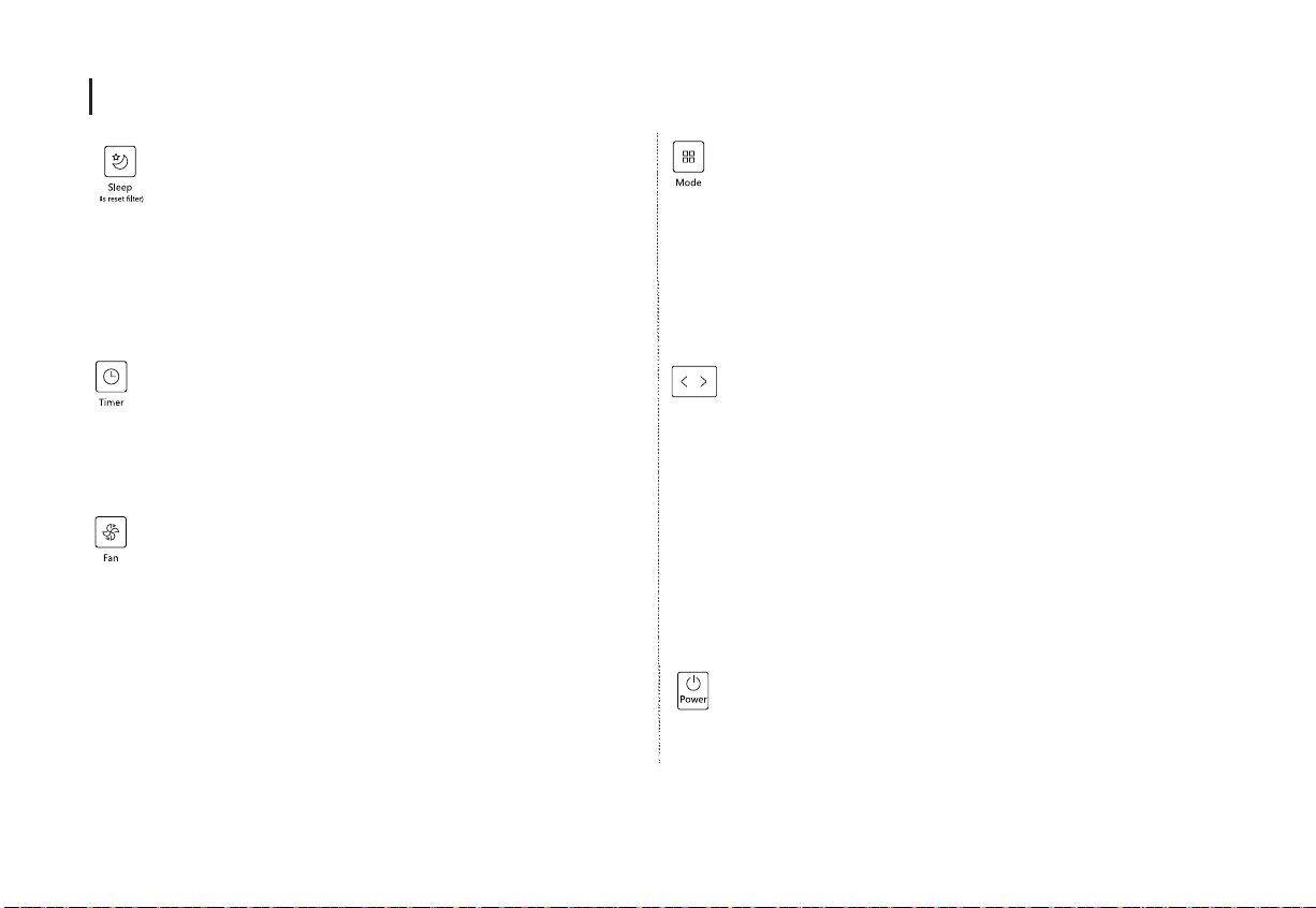
Sleep(Eco)/Filter button
Used to initiate the SLEEP/ECO operation.
NOTE: After 250 hours of operation, the filter
indicator light illuminates. This feature is a reminder
to clean the Air Filter for more efficient operation.
Press this button for 3 seconds to cancel the
reminder.
Timer button
Used to initiate the AUTO ON start time and AUTO
OFF stop time program, in conjuction with the + & -
buttons. The timer on/off indicator light illuminates
under the timer on/off settings.
Fan/Ion button(Ion is optional)
Control the fan speed. Press to select the fan speed
in four steps-LOW, MID(MED), HIGH and AUTO.
The fan speed indicator light illuminates under
different fan settings.
NOTE: Press this button for 3 seconds to initiate ION
feature. The ion generator is energized and will help
to remove pollen and impurities from the air, and trap
them in the filter. Press it for 3 seconds again to stop
the ION feature.
Mode button
Selects the appropriate operating mode. Each time
you press the button, a mode is selected in a
sequence that goes from AUTO, COOL, DRY, FAN
and HEAT (cooling only models without).The mode
indicator light illuminates under the different mode
settings.
Up (+) and Down (-) buttons
Used to adjust (increasing/decreasing) temperature
settings in 1°C/1°F (or 2°F) increments in
a range of 17°C/62°F to 30°C/86°F (or 88°F) or the
TIMER setting in a range of 0~24hrs.
NOTE: The control is capable of displaying
temperature in degrees Fahrenheit or degrees
Celsius. To convert from one to the other, press and
hold the Up and Down buttons at the same time for
3 seconds.
Power button
Power switch on/off.
12
Page 14

Operation
LED display
Shows the set temperature in °C or °F and the
Auto-timer settings. While on DRY and FAN modes,
it shows the room temperature.
Shows Error codes and protection code:
E1-Room temperature sensor error.
E2-Evaporator temperature sensor error.
E3-Condenser temperature sensor error (on some
models).
E4-Display panel communication error.
EC-Refrigerant leakage detection malfunction(on
some models).
E7-Zero-crossing malfunction.
P1-Bottom tray is full--Connect the drain hose and
drain the collected water away.If protection repeats,
call for service.
Note: When one of the above malfunctions occurs,
turn off the unit, and check for any obstructions.
Restart the unit, if the malfunction is still present,
turn off the unit and unplug the power cord.
Contact the manufacturer or its service agents or
a similar qualified person for service.
Operation Instructions
COOL operation
-Press the "MODE" button until the "COOL" indicator light
comes on.
-Press the ADJUST buttons "+" or "-" to select your desired
room temperature. The temperature can be set within a
range of 17°C~30°C/62°F~88°F(or 86°F).
-Press the "FAN SPEED" button to choose the fanspeed.
HEAT operation(cooling only models without)
-Press the "MODE" button until the "HEAT" indicator light
comes on.
-Press the ADJUST buttons "+" or " - " to select your
desired room temperature. The temperature can be set
within a range of 17°C~30°C/62°F~88°F (or 86°F).
-Press the "FAN SPEED" button to choose the fan speed.
For some models, the fan speed can not be adjusted
under HEAT mode.
DRY operation
-Press the "MODE" button until the "DRY" indicator light
comes on.
-Under this mode, you cannot select a fan speed or adjust
the temperature. The fan motor operates at LOW speed.
13
Page 15

Operation
-Keep windows and doors closed for the best
dehumidifying effect.
-Do not put the duct to window.
AUTO operation
-When you set the air conditioner in AUTO mode, it will
automatically select cooling, heating(cooling only models
without), or fan only operation depending on what
temperature you have selected and the room temperature.
-The air conditioner will control room temperature
automatically round the temperature point set by you.
-Under AUTO mode, you can not select the fan speed.
NOTE: Under AUTO mode, both the AUTO mode and the
actual operation mode indicator lights illuminate for the
unti with POWER MANAGEMENT feature.
FAN operation
-Press the "MODE" button until the"FAN " indicator light
comes on.
-Press the "FAN SPEED" button to choose the fan speed.
The temperature can not be adjusted.
-Do not put the duct to window.
TIMER operation
-When the unit is on, press the Timer button will initiate
the Auto-off stop program, the TIMER OFF indicator light
illuminates. Press the UP or DOWN button to select the
desired time. Press the TIMER button again within 5
seconds, the Auto-on start program is initiated. And the
TIMER ON indicator light illuminates. Press the up or down
button to select the desired Auto-on start time.
-When the unit is off, press the Timer button to initiate the
Auto-on start program, press it again within five seconds
will initiate the Auto-off stop program.
-Press or hold the UP or DOWN button to change the Auto
time by 0.5 hour increments, up to 10 hours, then at 1 hour
increments up to 24 hours. The control will count down the
time remaining until start.
-The system will automatically revert back to display the
previous temperature setting if there is no operation in a 5
seconds period.
-Turning the unit ON or OFF at any time or adjusting the
timer setting to 0.0 will cancel the Auto Start/Stop timer
program.
-When the malfunctionoccurs, the Auto Start/Stop timed
program will also be cancelled.
SLEEP/ECO operation
-Press this button, the selected temperature will increase
(cooling) or decrease(heating) by 1°C/2°F(or 1°F) 30
14
Page 16

Operation
minutes.The temperature will then increase (cooling) or
decrease (heating) by another 1°C/2°F(or 1°F) after an
additional 30 minutes. This new temperature will be
maintained for 7 hours before it returns to the originally
selected temperature. This ends the Sleep/Eco mode and
the unit will continue to operate as originally programmed.
NOTE: This feature is unavailabe under FAN or DRY
mode.
Other features
FOLLOW ME/TEMP SENSING feature(optional)
NOTE:This feature can be activated from the remote
control ONLY. The remote control servesas a remote
thermostat allowing for the precise temperature control at
its location. To activate the Follow Me/Temp Sensing
feature, point the remote control towards the unit and
press the Follow Me/Temp Sensing button. The remote
display is actual temperature at its location. The remote
control will send this signal to the air conditioner every 3
minutes interval until press the Follow Me/Temp Sensing
button again. If the unit does not receive the
Follow Me/Temp Sensing signal during any 7 minutes
interval, the unit will exit the Follow Me/Temp Sensing
mode. NOTE: This feature is unavailabe under FAN or
DRY mode.
AUTO-RESTART(on some models)
If the unit breaks off unexpectedly due to the power cut,it
will restart with the previous function setting automatically
when the power resumes.
WAIT 3 MINUTES BEFORE RESUMING OPERATION
After the unit has stopped, it can not be restarted operation
in the first 3 minutes. This is to protect the unit. Operation
will automatically start after 3 minutes.
AIR FLOW DIRECTION ADJUSTMENT
The louver can be adjusted automatically. Adjust the air flow
direction automatically :(NOTE:On some models the louver
can be adjusted manually only)
-When the Power is ON, the louver opens fully.
-Press the SWING button on the panel or remote controller
to initiate the Auto swing feature. The louver willl swing up
and down automatically.
-Please do not adjust the louver manually.
POWER MANAGEMENT feature(optional)
When the ambient temperature is lower than the setting
temperature for a period of time, the unit will be
automatically operate power management feature. The
compressor and fan motor stop. When the ambient
temperature is higher than the setting temperature, the unit
will be automatically quit the power management feature.
The compressor and (or) fan motor run.
15
Page 17
Operation
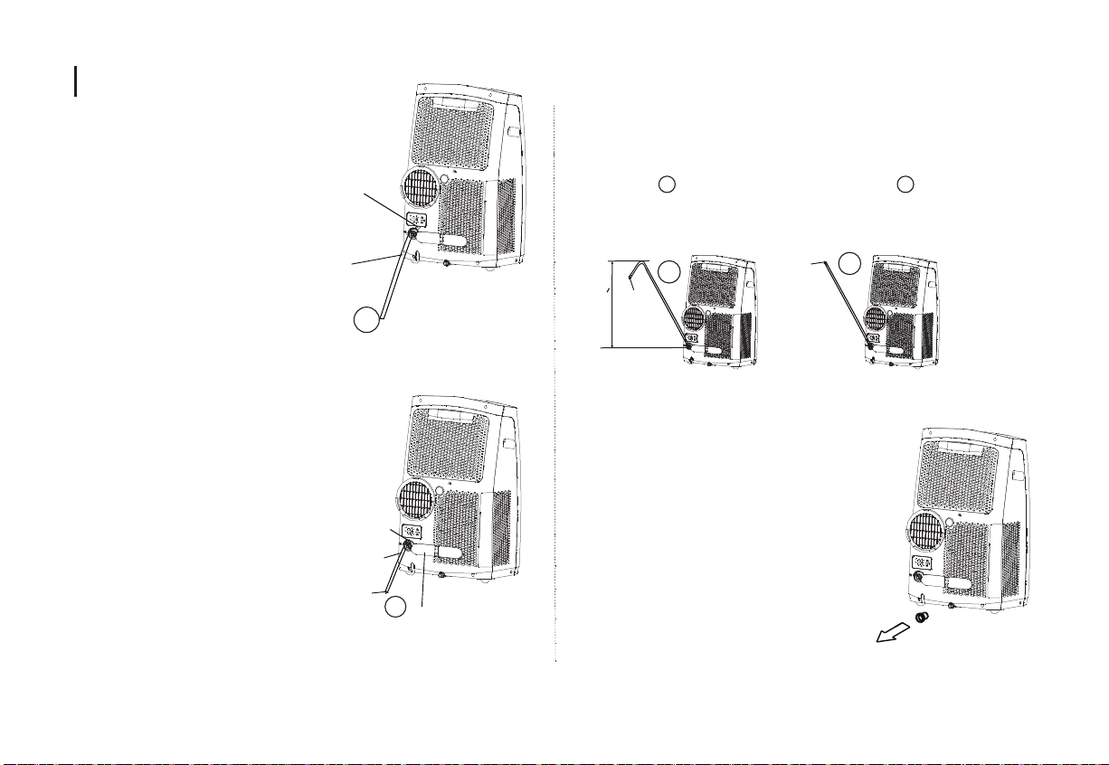
Water drainage
-During dehumidifying modes,
remove the upper drain plug
from the back of the unit,
install the drain connector(5/8"
universal female mender) with
3/4" hose(locally purchased).
For the models without drain
connector, just attach the drain
hose to the hole. Place the open
end of the hose directly over the
drain area in your basement floor.
-During heating pump mode, remove
the lower drain plug from the back
of the unit, install the drain connector
(5/8" universal female mender) with
3/4" hose(locally purchased). For
the models without drain connector,
just attach the drain hose to the
hole. Place the open end of the
Hose adaptor directly over the
drain area in your basement floor.
NOTE: Make sure the hose is
secure so there are no leaks.
Remove the
upper drain plug
Continuous
drain hose
Remove the
lower drain plug
Continuous
drain hose
drain hose
adaptor
√
√
Press the power
cord buckle into
the rear cover.
Direct the hose toward the drain, making sure that there are no kinks that
will stop the warter flowing.Place the end of the hose into he drain and
make sure the end of the hose is down to let the water flow smoothly.
(See Figs with . Do never let it up.(See Figs with ).When the
√ X
continuous drain hose is not used, ensure that the corresponding drain
plug and knob are installed firmly to prevent leakage.
√
drain hose
adaptor
delivery lift <1.8m
drain hose
adaptor
X
-When the water level of the bottom tray reaches
a predetermined level, the unit beeps 8 times,
the digital display area shows "P1" . At this time
the air conditioning/dehumidification process will
immediately stop. However, the fan motor will
continue to operate(this is normal). Carefully
move the unit to a drain location, remove the
bottom drain plug and let the water drain away.
Reinstall the bottom drain plug and restart the
machine until the "P1" symbol disappears.
If the error repeats, call for service.
NOTE: Be sure to reinstall the bottom drain
plug firmly to prevent leakage before using the unit.
16
Page 18
Maintenance
WARNING:
-Always unplug the unit before cleaning or servicing.
-DO NOT use flammable liquids or chemicals to clean the
unit.
-DO NOT wash the unit under running water. Doing so
causes electrical danger.
-DO NOT operate the machine if the power supply was
damaged during cleaning. A damaged power cord must be
replaced with a new cord from the manufacturer.
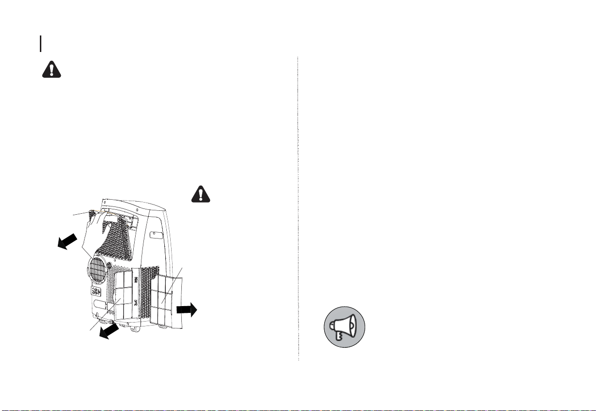
Clean the Air Filter
CAUTION
Upper filter
(take out)
lower filter B
(take out)
Remove the air filter
DO NOT operate the unit
without filter because dirt
and lint will clog it and
reduce performance.
lower filter A
(Press the grill down
slightly and pull the lower
filter A out at the same time)
Maintenance Tips
-Be sure to clean the air filter every 2 weeks for optimal
performance.
-The water collection tray should be drained immediately
after P1 error occurs, and before storage to prevent mold.
-In households with animals, you will have to periodically
wipe down the grill to prevent blocked airflow due to
animal hair.
Clean the Unit
Clean the unit using a damp, lint-free cloth and mild
detergent. Dry the unit with a dry lint-free cloth.
Store the unit when not in use
-Drain the unit’s water collection tray according to the
instructions in the following section.
-Run the appliance on FAN mode for 12 hours in a
warm room to dry it and prevent mold.
-Turn off the appliance and unplug it.
-Clean the air filter according to the instructions in the
previous section. Reinstall the clean, dry filter before
storing.
-Remove the batteries from the remote control.
Be sure to store the unit in a cool, dark
place. Exposure to direct sunshine or
extreme heat can shorten the lifespan
of the unit.
17
Page 19

Faults Diagnosis
Please check the machine according to the following form before asking for maintenance:
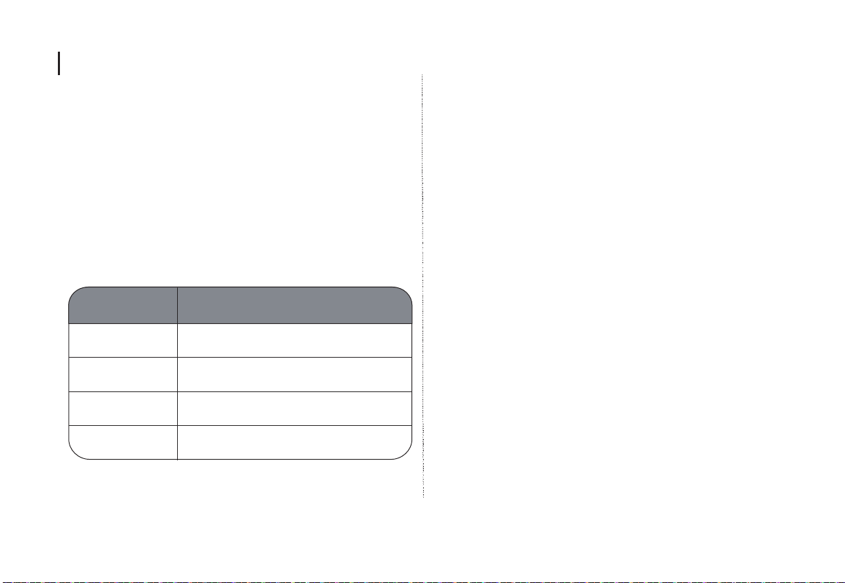
Problem Possible Cause
Troubleshooting
Unit does not
turn on when
pressing ON/OFF
button
Unit does not
cool well
The unit is noisy
and vibrates too
much
The unit makes a
gurgling sound
P1 Error Code
In COOL mode: room temperature is lower than
the set temperature
The air filter is blocked with dust or animal hair
Exhaust hose is not connected or is blocked
The unit is low on refrigerant
Temperature setting is too high
The windows and doors in the room are open
The room area is too large
There are heat sources inside the room
The ground is not level Place the unit on a flat, level surface
The air filter is blocked with dust or animal hair
This sound is caused by the flow of refrigerant
inside the unit
The Water Collection Tray is full. Turn off the unit, drain
the water from the Water Collection Tray and restart the unit.
Reset the temperature
Turn off the unit and clean the filter according to instructions
Turn off the unit, disconnect the hose, check for blockage and
reconnect the hose
Call a service technician to inspect the unit and top off refrigerant
Decrease the set temperature
Make sure all windows and doors are closed
Double-check the cooling area
Remove the heat sources if possible
Turn off the unit and clean the filter according to instructions
This is normal
18
Page 20
Design and Compliance Notes
Design Notice
In order to ensure the optimal performance of our products,
the design specifications of the unit and remote control are
subject to change without prior notice.
Energy Rating Information
The Energy Rating for this unit is based on an installation
using an un-extended exhaust duct without window slider
adaptor or wall exhaust adaptor A (as shown in the
Installation section of this manual)
Unit Temperature Range
Mode Temperature Range
Cool 17-35°C (62-95°F)
Note:The model MPPFB-11CRN7-QB6 should be
connected only to a supply with the relevant system
impedance no more than 0.373 ohm. Restrictions to
connection may be imposed by the supply authority
on the use of equipment in the actual relevant system
impedance at the interface point on the user’s premise
exceeds 0. 373 ohm.
Exhaust hose installation:
The exhaust hose and adaptor must be installed or
removed in accordance with the usage mode.
For COOL,HEAT(heat pump type) or AUTO mode
must be installed exhaust hose.
For FAN,DEHUMIDIIFY or HEAT(electrical heat
type) mode must be removed exhaust hose.
Dry
Heat(pump heat
mode)
Heat(electrical
heat mode)
13-35°C (55-95°F)
5-30°C (41-86°F)
≤
30°C (86°F)
19
Page 21
Sociable Remark
When using this dehumidifier in the European countries, the following information must be followed:
DISPOSAL: Do not dispose this product as unsorted municipal waste. Collection of such waste separately
for special treatment is necessary.
It is prohibited to dispose of this appliance in domestic household waste.
For disposal, there are several possibilities:
A) The municipality has established collection systems, where electronic waste can be disposed of at least
free of charge to the user.
B) When buying a new product, the retailer will take back the old product at least free of charge.
C) The manufacture will take back the old appliance for disposal at least free of charge to the user.
D) As old products contain valuable resources, they can be sold to scrap metal dealers.
Wild disposal of waste in forests and landscapes endangers your health when hazardous substances leak
into the ground-water and find their way into the food chain.
20
Page 22

Other tips
1.Transport of equipment containing flammable refrigerants
See transport regulations
2.Marking of equipment using signs
See local regulations
3.Disposal of equipment using flammable refrigerants
See national regulations.
4.Storage of equipment/appliances
The storage of equipment should be in accordance with the
manufacturer's instructions.
5.Storage of packed (unsold) equipment
Storage package protection should be constructed such
that mechanical damage to the equipment inside the
package will not cause a leak of the refrigerant charge.
The maximum number of pieces of equipment permitted to
be stored together will be determined by local regulations.
6.Information on servicing
1)Checks to the area
Prior to beginning work on systems containing flammable
refrigerants, safety checks are necessary to ensure that the
risk of ignition is minimised. For repair to the refrigerating
system, the following precautions shall be complied with
prior to conducting work on the system.
2)Work procedure
Work shall be undertaken under a controlled procedure so
as to minimise the risk of a flammable gas or vapour being
present while the work is being performed.
3)General work area
All maintenance staff and others working in the local area
shall be instructed on the nature of work being carried out.
Work in confined spaces shall be avoided. The area
around the workspace shall be sectioned off. Ensure that
the conditions within the area have been made safe by
control of flammable material.
4)Checking for presence of refrigerant
The area shall be checked with an appropriate refrigerant
detector prior to and during work, to ensure the technician
is aware of potentially flammable atmospheres. Ensure
that the leak detection equipment being used is suitable
for use with flammable refrigerants,
i.e. non-sparking, adequately sealed or intrinsically safe.
5)Presence of fire extinguisher
If any hot work is to be conducted on the refrigeration
equipment or any associated parts, appropriate fire
extinguishing equipment shall be available to hand. Have
a dry powder or CO2 fire extinguisher adjacent to the
charging area.
6)No ignition sources
No person carrying out work in relation to a refrigeration
system which involves exposing any pipe work that
contains or has contained
flammable refrigerant shall use any sources of ignition in
such a manner that it may lead to the risk of fire or
21
Page 23

Other tips
explosion. All possible ignition sources, including cigarette
smoking, should be kept sufficiently far away from the site
of installation, repairing, removing and disposal, during
which flammable refrigerant can possibly be released to the
surrounding space. Prior to work taking place, the area
around the equipment is to be surveyed to make sure that
there are no flammable hazards or ignition risks. No
Smoking signs shall be displayed.
7)Ventilated area
Ensure that the area is in the open or that it is adequately
ventilated before breaking into the system or conducting
any hot work. A degree of ventilation shall continue during
the period that the work is carried out. The ventilation
should safely disperse any released refrigerant and
preferably expel it externally into the atmosphere.
8)Checks to the refrigeration equipment
Where electrical components are being changed, they shall
be fit for the purpose and to the correct specification. At all
times the manufacturer's maintenance and service
guidelines shall be followed. If in doubt consult the
manufacturer's technical department for assistance. The
following checks shall be applied to installations using
flammable refrigerants:
The charge size is in accordance with the room size within
which the refrigerant containing parts are installed;
The ventilation machinery and outlets are operating
adequately and are not obstructed;
If an indirect refrigerating circuit is being used, the
secondary circuit shall be checked for the presence of
refrigerant; Marking to the equipment continues to be
visible and legible. Markings and signs that are illegible
shall be corrected;
Refrigeration pipe or components are installed in a
position where they are unlikely to be exposed to any
substance which may corrode refrigerant containing
components, unless the components are constructed of
materials which are inherently resistant to being corroded
or are suitably protected against being so corroded.
9)Checks to electrical devices
Repair and maintenance to electrical components shall
include initial safety checks and component inspection
procedures. If a fault exists that could compromise safety,
then no electrical supply shall be connected to the circuit
until it is satisfactorily dealt with. If the fault cannot be
corrected immediately but it is necessary to continue
operation, an adequate temporary solution shall be used.
This shall be reported to the owner of the equipment so
all parties are advised.
Initial safety checks shall include:
That capacitors are discharged: this shall be done in a
safe manner to avoid possibility of sparking;
That there no live electrical components and wiring are
22
Page 24

Other tips
exposed while charging, recovering or purging the system;
That there is continuity of earth bonding.
7.Repairs to sealed components
1)During repairs to sealed components, all electrical
supplies shall be disconnected from the equipment being
worked upon prior to any removal of sealed covers, etc. If it
isabsolutely necessary to have an electrical supply to
equipment during servicing, then a permanently operating
form of leak detection shall be located at the most critical
point to warn of a potentially hazardous situation.
2)Particular attention shall be paid to the following to ensure
that by working on electrical components, the casing is not
altered in such a way that the level of protection is affected.
This shall include damage to cables, excessive number of
connections, terminals not made to original specification,
damage to seals, incorrect fitting of glands, etc.
Ensure that apparatus is mounted securely.
Ensure that seals or sealing materials have not degraded
such that they no longer serve the purpose of preventing the
ingress of flammable atmospheres. Replacement parts shall
be in accordance with the manufacturer's specifications.
NOTE: The use of silicon sealant may inhibit the
effectiveness of some types of leak detection
equipment. Intrinsically safe components do not have to
be isolated prior to working on them.
8.Repair to intrinsically safe components
Do not apply any permanent inductive or capacitance
loads to the circuit without ensuring that this will not
exceed the permissible voltage and current permitted for
the equipment in use. Intrinsically safe components are
the only types that can be worked on while live in the
presence of a flammable atmosphere. The test apparatus
shall be at the correct rating. Replace components only
with parts specified by the manufacturer. Other parts may
result in the ignition of refrigerant in the atmosphere from
a leak.
9.Cabling
Check that cabling will not be subject to wear, corrosion,
excessive pressure, vibration, sharp edges or any other
adverse environmental effects. The check shall also take
into account the effects of aging or continual vibration
from sources such as compressors or fans.
10.Detection of flammable refrigerants
Under no circumstances shall potential sources of ignition
be used in the searching for or detection of refrigerant
leaks. A halide torch (or any other detector using a naked
flame) shall not be used.
11.Leak detection methods
he following leak detection methods are deemed
acceptable for systems containing flammable refrigerants.
Electronic leak detectors shall be used to detect flammable
refrigerants, but the sensitivity may not be adequate, or
23
Page 25

Other tips
may need re-calibration. (Detection equipment shall be
calibrated in a refrigerant-free area.) Ensure that the
detector is not a potential source of ignition and is suitable
for the refrigerant used. Leak detection equipment shall be
set at a percentage of the LFL of the refrigerant and shall be
calibrated to the refrigerant employed and the appropriate
percentage of gas (25 % maximum) is confirmed. Leak
detection fluids are suitable for use with most refrigerants
but the use of detergents containing chlorine shall be
avoided as the chlorine may react with the refrigerant and
corrode the copper pipe-work. If a leak is suspected, all
naked flames shall be removed/ extinguished. If a leakage
of refrigerant is found which requires brazing, all of the
refrigerant shall be recovered from the system, or isolated
(by means of shut off valves) in a part of the system remote
from the leak. Oxygen free nitrogen (OFN) shall then be
purged through the system both before and during the
brazing process.
12.Removal and evacuation
When breaking into the refrigerant circuit to make repairs
or for any other purpose conventional procedures shall be
used. However, it is important that best practice is followed
since flammability is a consideration. The following
procedure shall be adhered to:
Remove refrigerant;
Purge the circuit with inert gas;
Evacuate;
Purge again with inert gas;
Open the circuit by cutting or brazing.
The refrigerant charge shall be recovered into the correct
recovery cylinders. The system shall be flushed with OFN
to render the unit safe. This process may need to be
repeated several times. Compressed air or oxygen shall
not be used for this task.
Flushing shall be achieved by breaking the vacuum in the
system with OFN and continuing to fill until the working
pressure is achieved, then venting to atmosphere, and
finally pulling down to a vacuum. This process shall be
repeated until no refrigerant is within the system. When
the final OFN charge is used, the system shall be vented
down to atmospheric pressure to enable work to take
place. This operation is absolutely vital if brazing
operations on the pipe-work are to take place.
Ensure that the outlet for the vacuum pump is not close to
any ignition sources and there is ventilation available.
13.Charging procedures
In addition to conventional charging procedures, the
following requirements shall be followed.
Ensure that contamination of different refrigerants does
not occur when using charging equipment. Hoses or lines
shall be as short as possible to minimise the amount of
refrigerant contained in them.
24
Page 26

Other tips
Extreme care shall be taken not to overfill the refrigeration
system. Prior to recharging the system it shall be pressure
tested with OFN. The system shall be leak tested on
completion of charging but prior to commissioning. A follow
up leak test shall be carried out prior to leaving the site.
14.Decommissioning
Before carrying out this procedure, it is essential that the
technician is completely familiar with the equipment and all
its detail. It is recommended good practice that all
refrigerants are recovered safely. Prior to the task being
carried out, an oil and refrigerant sample shall be taken in
case analysis is required prior to re-use of reclaimed
refrigerant. It is essential that electrical power is available
before the task is commenced.
a) Become familiar with the equipment and its operation.
b) Isolate system electrically.
c) Before attempting the procedure ensure that:
Mechanical handling equipment is available, if required, for
handling refrigerant cylinders;
All personal protective equipment is available and being
used correctly; The recovery process is supervised at all
times by a competent person;
Recovery equipment and cylinders conform to the
appropriate standards.
d) Pump down refrigerant system, if possible.
e) If a vacuum is not possible, make a manifold so that
refrigerant can be removed from various parts of the
system.
f) Make sure that cylinder is situated on the scales before
recovery takes place.
g) Start the recovery machine and operate in accordance
with manufacturer's instructions.
h) Do not overfill cylinders. (No more than 80 % volume
liquid charge).
i) Do not exceed the maximum working pressure of the
cylinder, even temporarily.
j) When the cylinders have been filled correctly and the
process completed, make sure that the cylinders and the
equipment are removed from site promptly and all
isolation valves on the equipment are closed off.
k) Recovered refrigerant shall not be charged into another
refrigeration system unless it has been cleaned and
checked.
15.Labelling
Equipment shall be labelled stating that it has been
de-commissioned and emptied of refrigerant. The label
shall be dated and signed. Ensure that there are labels
on the equipment stating the equipment contains
flammable refrigerant.
16.Recovery
When removing refrigerant from a system, either for
servicing or decommissioning, it is recommended good
25
Page 27

Other tips
practice that all refrigerants are removed safely.
When transferring refrigerant into cylinders, ensure that only
appropriate refrigerant recovery cylinders are employed.
Ensure that the correct number of cylinders for holding the
total system charge is available. All cylinders to be used are
designated for the recovered refrigerant and labelled for that
refrigerant (i.e. special cylinders for the recovery of
refrigerant). Cylinders shall be complete with pressure relief
valve and associated shut-off valves in good working order.
Empty recovery cylinders are evacuated and, if possible,
cooled before recovery occurs.
The recovery equipment shall be in good working order with
a set of instructions concerning the equipment that is at hand
and shall be suitable for the recovery of flammable
refrigerants. In addition, a set of calibrated weighing scales
shall be available and in good working order. Hoses shall
be complete with leak-free disconnect couplings and in good
condition. Before using the recovery machine, check that it
is in satisfactory working order, has been properly
maintained and that any associated electrical components
are sealed to prevent ignition in the event of a refrigerant
release. Consult manufacturer if in doubt.
The recovered refrigerant shall be returned to the refrigerant
supplier in the correct recovery cylinder, and the relevant
Waste Transfer Note arranged. Do not mix refrigerants in
recovery units and especially not in cylinders. If compressors
or compressor oils are to be removed, ensure that they
have been evacuated to an acceptable level to make
certain that flammable refrigerant does not remain within
the lubricant. The evacuation process shall be carried out
prior to returning the compressor to the suppliers. Only
electric heating to the compressor body shall be employed
to accelerate this process. When oil is drained from a
system, it shall be carried out safely.
26
Page 28

GD MIDEA AIR-CONDITIONING EQUIPMENT CO.,LTD.
Lingang Road Beijiao Shunde Foshan Guangdong People’s
Republic of China 528311
Page 29

Manuale utente e installazione
SOGNIDORO-09E
SOGNIDORO-12E
MPPFB-09CRN7
Nota Importante
Leggere con attenzione questo manuale prima di utilizzare il prodotto e conservarlo per la consultazione futura.
Page 30

Sommario
Precauzioni di sicurezza pag. 3-4
Preparazione pag. 5
Installazione pag. 6-10
Funzionamento pag. 11-13
Manutenzione pag. 14
Soluzione Inconvenienti pag. 15
Progettazione e Conformità pag. 15
Smaltimento del prodotto pag. 16
2
Page 31

Precauzioni di sicurezza Precauzioni di sicurezza
Attenzione: leggere queste indicazioni prima di utilizzare il prodotto.
• La non corretta installazione del prodotto può essere causa di danni o lesioni.
• L’installazione e la manutenzione devono essere eseguite in conformità con le norme
vigenti, da personale autorizzato.
• Utilizzare unicamente accessori e componenti originali per l’installazione del prodotto.
• L’impiego di parti e componenti non originali può causare perdite d'acqua, scosse
elettriche, incendio o danni a cose e persone. Assicurarsi che l'alimentazione elettrica al
prodotto sia operata attraverso una presa collegata a terra e caratterizzata da tensione
adeguata.
• Il cavo elettrico del prodotto è dotato di una spina equipaggiata con connettore di
terra. Le caratteristiche della tensione di alimentazione possono essere rilevate dalla
targhetta del prodotto applicata sul retro dello stesso.
• Assicurarsi che l'unità sia posizionata su una superficie piana e orizzontale. La mancata
osservanza di questa prescrizione può causare danni o l'emissione di rumori e vibrazioni
eccessive.
• Le aperture delle unità devono essere libere da ostacoli e garantire un corretto
transito dell'aria attraverso di esse.
• Non modificare la lunghezza del cavo di alimentazione del prodotto e non utilizzare
cavi di prolunga di tipologia non idonea. Non utilizzare multi-prese e adattatori di altra
tipologia per suddividere il collegamento di una presa comune con altri dispositivi.
L'applicazione impropria di adattatori o altri sistemi per la condivisione di prese
elettriche può causare incendio o scosse elettriche.
• Non installare il prodotto in locali molto umidi quali bagni e lavanderie. L'eccessiva
umidità presente in questi ambienti può causare danni ai componenti elettrici e
provocare cortocircuiti.
• Non installare il prodotto in locali che possono essere esposti alla presenza di gas
combustibili o esplosivi. L'inosservanza di questa prescrizione può causare il rischio di
incendio o esplosione.
• Il prodotto è dotato di ruote piroettanti per il trasporto. Non utilizzare il prodotto su
tappeti o superfici irregolari. Si potrebbero causare danni alle ruote.
• In caso di necessità di riparazione o assistenza da prestare al prodotto, contattare il
rivenditore o un centro assistenza tecnica autorizzato dal costruttore degli apparecchi.
• Non connettere all'alimentazione elettrica ed utilizzare un prodotto che appare aver
subito un urto o danneggiato.
• Se il funzionamento del prodotto appare improprio o irregolare o se si avvertono
sintomi anormali durante l'utilizzo del prodotto, arrestare immediatamente il prodotto
e disconnetterlo dall'alimentazione elettrica.
• Ispezionare il prodotto visivamente per verificare che non siano presenti danni. Se si
sospetta che sia presente un danno o un malfunzionamento di qualunque natura,
contattare il venditore o il centro assistenza tecnica autorizzato dal produttore più
vicino.
• In caso di temporali, scollegare il prodotto dalla presa elettrica per evitare che possa
essere danneggiato dai fulmini o dalle scariche atmosferiche.
• Il prodotto non deve essere utilizzato dai minori di anni 8 o da persone anche di età
superiore, che non siano in possesso di adeguata capacità fisiche, mentali o motorie, o
che non abbiano esperienza specifica nell’impiego del prodotto stesso. Gli utilizzatori
devono essere consapevoli dell’uso del prodotto in maniera sicura e devono essere
informati sui rischi e sui danni che possono essere cagionati dall’utilizzo non corretto. I
bambini non devono utilizzare il prodotto come giocattolo. La pulizia e la manutenzione
del prodotto non devono essere eseguite da bambini
• I bambini devono sempre essere sorvegliati quando si trovano in prossimità del
condizionatore.
• Se il cavo di alimentazione è danneggiato, non utilizzare il prodotto e scollegarlo
immediatamente dalla presa elettrica. Il cavo danneggiato deve essere sostituito da un
centro assistenza tecnica autorizzato dal produttore con uno di tipologia adeguata.
• Prima di ogni operazione di movimentazione, pulizia e manutenzione del prodotto,
rimuovere la spina di alimentazione dalla presa.
• Non applicare al cavo di alimentazione del prodotto nessun tipo di variatore di
velocità o sistema di controllo esterno: si possono generare incendi.
3
Page 32

Precauzioni di sicurezza
PERICOLO
• Questo prodotto contiene refrigerante R290 classificato come infiammabile.
• Non utilizzare dispositivi o mezzi non ammessi dal produttore per accelerare i processi di sbrinamento o per rimuovere il ghiaccio dagli scambiatori di calore.
• Il prodotto deve essere conservato in ambienti chiusi privi di potenziali fonti di innesco (Es. fiamme libere, riscaldatori elettrici o a gas, etc.).
• Non perforare o bruciare l’unità.
• Il fluido refrigerante contenuto nel prodotto è inodore.
• L’unità deve essere conservata in ambienti ben ventilati la cui superficie corrisponde ad almeno 12m2.
• Rispettare le normative sui refrigeranti infiammabili vigenti nel territorio di applicazione del prodotto.
• Mantenere tutte le aperture di ventilazione del prodotto libere da ostruzioni.
• Conservare il prodotto in luoghi dove possano essere evitati danneggiamenti meccanici dello stesso.
• Il personale addetto alle riparazioni o alla manutenzione del prodotto deve essere in possesso delle corrette conoscenze sul prodotto e sul tipo di fluido refrigerante da esso impiegato.
• Si raccomanda di contattare il venditore o un centro assistenza tecnica autorizzato dal produttore per le attività di verifica sul prodotto stesso.
4
Page 33

Preparazione
Display
Deflettori aria
Alloggiamento per spina elettrica
Filtro aria superiore
(contenuto nel telaio in plastica)
Maniglie
(Sui fianchi del prodotto)
Aspirazione aria superiore
Scarico liquido condensa
Espulsione aria
Filtro aria inferiore
Aspirazione aria inferiore
Vista Frontale
Passaggio cavo di alimentazione
Ruote piroettanti
Avvolgicavo
Scarico liquido condensa
(Da impiagare in caso di svuotamento in caso di inattività)
5
Vista Posteriore
Page 34

Installazione
Selezione del luogo di installazione
Il luogo di installazione selezionato per il prodotto deve soddisfare i seguenti requisiti:
• Essere caratterizzato da una superficie piana e solida per evitare la propagazione di
vibrazioni e rumori.
• Essere prossimo a una presa di elettricità provvista di collegamento di terra.
• Essere in grado di alloggiare il contenitore per lo scarico del liquido di condensa o in
prossimità di un punto di scarico.
• L’unità deve distare da pareti o altri ostacoli almeno 30 cm.
• Le aperture di aspirazione e mandata aria, oltre che il ricevitore del comando
infrarossi devono essere libere da oggetti che possano ostruirle anche solo
parzialmente.
Le immagini contenute nel manuale sono da intendersi come indicative. Il reale aspetto
del prodotto, dei componenti e degli accessori, può differire da quanto indicato. Il
manuale non comprende informazioni relative al telecomando, contenute in un
fascicolo separato.
Il mancato rispetto delle indicazioni sopra può causare malfunzionamento e danni al
prodotto.
6
Page 35

Installazione
Attrezzature necessarie
• Cacciavite Philips dimensione media
• Metro a nastro
• Seghetto per metalli (in caso sia necessario accorciare l’adattatore finestra)
Accessori
L’adattatore finestra si alloggia in serramenti di larghezza compresa tra 67 e 123 cm. In
caso di larghezza inferiore, è necessario accorciare l’adattatore tagliando la parte
eccedente.
Componente Descrizione Quantità
Raccordo unità, tubo estensibile, raccordo per
adattatore finestra, raccordo per tappo a parete
Tappo a parete 1 pezzo
Adattatore finestra (composto da 2 parti) 1 pezzo
Viti e tasselli 1 sacchetto
Sigillante
Piastrina e viti 1 sacchetto
Tubo scarico condensa 1 pezzo
1 pezzo
ciascuno
5 pezzi
assortiti
Assemblaggio del tubo di espulsione aria
Assemblare la tubazione espulsione aria applicando su un lato il raccordo per l’unità e
sull’altro il raccordo per l’adattatore finestra o quello per il tappo a parete, in funzione
della condizione di installazione da utilizzare
Tubo espulsione aria
con raccordo per
Tubazione estensibile
Raccordo per unità
Tubazione estensibile
Raccordo per
adattatore
finestra
adattatore a finestra
Tubo espulsione aria
con raccordo per
tappo a muro
Avvolgicavo 1 pezzo
Telecomando e batterie (Opzionale) 1 Pezzo
Gli accessori forniti a corredo con i prodotti potrebbero differire da quelli indicati in
relazione al mercato di destinazione dei prodotti.
.
Raccordo per unità
Raccordo per
tappo a muro
7
Page 36

Installazione
NOTA
Applicare l’estremità del tubo opposta a quella del raccordo dell’adattatore nella
macchina, facendo scorrere il raccordo nel senso indicato dalla freccia
Gli accessori forniti a corredo con i prodotti potrebbero differire da quelli indicati in
relazione al mercato di destinazione dei prodotti.
REGOLAZIONE LARGHEZZA ADATTATORE
In relazione alla larghezza della finestra fare scorrere la parte interna dell’adattatore
fino a raggiungere la dimensione desiderata.
1 Afferrare le due parti del
kit finestra con le mani.
Gli accessori forniti a corredo con i prodotti potrebbero differire da quelli indicati in
relazione al mercato di destinazione dei prodotti.
2 Estrarre il kit finestra sino
alla larghezza della finestra.
4 Applicare la vite di fissaggio nel
foro immediatamente prossimo alla
posizione segnata per assicurare che
la larghezza del pezzo rimanga
costante
3 Segnale la posizione che
la parte scorrevole
dell’adattatore deve
assumere.
8
Page 37

Installazione
FINESTRA CON ANTA SCORREVOLE VERTICALE
Sigillante
Sigillante
1 Applicare il nastro sigillante
al perimetro della finestra.
2 Applicare il Kit finestra al serramento ed
espandere lo scorrevole fino a compensare
la larghezza del serramento stesso.
Viti
Kit finestra
Piastrina
FINESTRA CON ANTA SCORREVOLE ORIZZONTALE
Sigillante
Sigillante
1 Applicare il nastro
sigillante al perimetro della
finestra.
2 Applicare il Kit finestra al serramento ed
espandere lo scorrevole fino a compensare la
larghezza del serramento stesso.
Kit finestra
Kit finestra
Piastrina
3 Chiudere l’anta scorrevole
fino a farla aderire
all’adattatore finestra.
4 Inserire ulteriore sigillante nelle aree rimaste
aperte per completare la sigillatura. Se necessario,
fissare con la finestra con la piastrina e le viti
3 Chiudere l’anta scorrevole
fino a farla aderire
all’adattatore finestra.
9
Viti
4 Inserire ulteriore sigillante nelle aree rimaste
aperte per completare la sigillatura. Se necessario,
fissare con la finestra con la piastrina e le viti
Page 38

Installazione
FINESTRA CON ANTA SCORREVOLE VERTICALE E ORIZZONTALE
5 Collegare il
prodotto con la
tubazione e i
raccordi a
corredo
all’adattatore
per metterlo in
servizio Inserire
ulteriore
sigillante nelle
aree rimaste
aperte per
completare la
sigillatura.
FORO SCARICO ARIA A PARETE
• Realizzare nella parete un foro da 125mm di diametro
• Applicare il tappo a parete al foro utilizzando i tasselli e le viti fornite a corredo
• Collegare il raccordo per lo scarico a parete al tappo a muro
• Collegare il tubo estensibile all’unità
Per garantire un corretto
funzionamento, non realizzare curve
sulla tubazione e non estendere lo
prolungare la tubazione rispetto alla
lunghezza massima
DRENAGGIO LIQUIDO CONDENSA
Durante la modalità Dry e in caso di
utilizzo della modalità Cool con
elevati valori di umidità ambientale,
collegare la tubazione di scarico
liquido di condensa al bocchettone
indicato, dopo aver rimosso il tappo
in gomma.
Fare in modo che l’estremità del
tubo rimanga aperta e non entri in
contatto con il liquido contenuto nel
recipiente di raccolta.
Lo scarico condensa avviene per gravità. Il tubo non deve realizzare percorsi verso
una posizione superiore a quella del bocchettone di scarico.
Se il livello del liquido di condensa nel
serbatoio dell’unità supera il livello
massimo ammesso, l’unità sospende il
funzionamento ed emette una sequenza
di 8 segnali acustici al termine dei quali è
visualizzato il codice guasto P1.
In questa condizione il ventilatore
continua a funzionare.
Per ripristinare il funzionamento del
prodotto, rimuovere il tappo di scarico
del liquido di condensa posto sul fondo
dell’unità e far drenare tutto il liquido
accumulato nel prodotto. Al termine,
riposizionare il tappo e riavviare il
prodotto.
10
Page 39

Funzionamento
Power
Accensione/spegnimento
dell’unità
Swing
Avvio/arresto della
oscillazione continua dei
deflettori aria. Se premuto
durante l’oscillazione, il
deflettore si arresta nella
posizione in cui si trova
Sleep
Avvio/arresto della modalità
Sleep.
Se premuto per 3 secondi
consecutivamente, resetta il
segnale pulizia filtri.
Timer
Se premuto a unità spenta attiva
la funzione Timer On. Se
premuto a unità avviata, attiva
la funzione Timer Off.
Dopo la pressione del pulsante,
premere i pulsanti +/- per
impostare il numero di ore
impostate per lo
spegnimento/accensione
11
Fan
Regolazione della velocità del
ventilatore: ad ogni pressione
la velocità cambia nella
sequenza Low-Mid-High-Auto
Mode
Variazione della modalità
operativa: ad ogni pressione
la modalità varia tra AutoCool-Dry-Fan.
+/Regolazione della temperatura
impostata (1°C per pressione).
In caso ditimer permette di regolare
gli orari di attivazione/spegnimento
differito tra 0 e 24h.
Se premuti contemporaneamente
per 3 secondi, commutano
l’indicazione temperatura in °F.
Page 40

Funzionamento
DISPLAY LED
Il display mostra la temperatura impostata per il funzionamento in °C o °F e viene
utilizzato per visualizzare le modalità di impostazione del timer.
In caso di modalità Dry o Fan, il display mostra il valore della temperatura ambiente.
Il display mostra anche i codici guasto in caso di avaria del sistema:
E1 Avaria sensore temperatura ambiente
E2 Avaria sensore temperatura evaporatore
E3 Avaria sensore temperatura condensatore
E4 Errore comunicazione scheda elettronica principale-diplay
EC Anomalia funzionamento circuito frigorifero
E7 Avaria EEPROM
P1 Livello acqua eccessivo
In caso di ripetuta manifestazione dei codici guasto, interrompere il funzionamento e
contattare il rivenditore.
INDICATORE PULIZIA FILTRI
Se il prodotto opera per un periodo di tempo complessivo superiore ai 250 ore, il LED
Filter sul display si illumina per ricordare la necessità di pulire i filtri aria del prodotto.
Questa indicazione non è in alcun modo rappresentativa dell’effettiva condizione dei
filtri aria.
Per eseguire il reset del contatore che determina l’illuminazione del LED Filter,
mantenere premuto il pulsante Sleep del display per almeno 3 secondi
consecutivamente, dopo aver ispezionato ed eventualmente pulito i filtri aria.
ISTRUZIONI PER L’USO
FUNZIONAMENTO IN MODALITÀ RAFFREDDAMENTO
Premere il pulsante Mode sino a quando il LED della sezione Mode non visualizza la
funzione Cool. Selezionare la temperatura impostata sul valore più opportuno
(compreso tra 18°C-30°C). Premere il pulsante Fan Speed fino a determinare la velocità
di rotazione del ventilatore desiderata.
FUNZIONAMENTO IN MODALITÀ DEUMIDIFICAZIONE
Premere il pulsante Mode sino a quando il LED della sezione Mode non visualizza la
funzione Dry. Durante l'utilizzo del prodotto in questa modalità non è possibile
impostare la temperatura desiderata in ambiente e selezionare la velocità di rotazione
del ventilatore. Il ventilatore ruota costantemente alla velocità minima.
Durante l'utilizzo del prodotto in modalità dry non collegare il tubo per l'espulsione aria
all'esterno del locale.
FUNZIONAMENTO IN MODALITÀ SOLA VENTILAZIONE
Premere il pulsante Mode sino a quando il LED della sezione Mode non visualizza la
funzione Fan. Durante l'utilizzo del prodotto in questa modalità non è possibile
impostare la temperatura desiderata in ambiente. Premere il pulsante Fan Speed fino a
determinare la velocità di rotazione del ventilatore desiderata. Durante l'utilizzo del
prodotto in modalità Fan non collegare il tubo per l'espulsione aria all'esterno del locale.
FUNZIONAMENTO IN MODALITÀ AUTOMATICA
Premere il pulsante Mode sino a quando il LED della sezione Mode non visualizza la
funzione Auto.
12
Page 41

Funzionamento
Durante l'utilizzo in modalità Auto il sistema deciderà automaticamente se impiegare la
modalità raffreddamento o la modalità ventilazione in funzione della temperatura che è
stata selezionata per l'ambiente.
In questa modalità operativa non è possibile regolare la velocità di rotazione del
ventilatore.
Timer
Ad unità attiva, premere il pulsante Timer per attivare la funzione timer Off. Il led timer
off si illumina ed è possibile premere i pulsanti di regolazione della temperatura per
definire il numero di ore dopo cui avverrà lo spegnimento. Premere nuovamente, entro
5 secondi, il pulsante Timer per accedere alla funzione timer On.
Ad unità arrestata, premere il pulsante Timer per attivare la funzione timer On. Il led
timer off si illumina ed è possibile premere i pulsanti di regolazione della temperatura
per definire il numero di ore dopo cui avverrà l’avviamento. Premere nuovamente,
entro 5 secondi, il pulsante Timer per accedere alla funzione timer Off.
I pulsanti +/-per la regolazione della temperatura permettono di impostare gli orari di
accensione o spegnimento del prodotto a intervalli di 30 minuti entro il campo di
impostazione delle prime 10 ore e a intervalli di un'ora nel campo di impostazione
rappresentato dalle successive 14 ore.
In caso di mancata esecuzione di qualunque funzione per più di 5 secondi, il display
ritornerà alla normale modalità di visualizzazione.
L’avvio o lo spegnimento del prodotto durante l'attesa per l'avvio o lo spegnimento
differito mediante timer annulla la funzione Timer stessa.
La funzione Timer si cancella anche in caso di intervento di un codice guasto.
La funzione Sleep non è attiva durante l'utilizzo del prodotto in modalità
deumidificazione e sola ventilazione.
ALTREFUNZIONALITA’OPZIONALI
Follow Me (Opzionale)
Questa funzionalità può essere attivata esclusivamente dal comando a infrarossi. Il
comando a infrarossi è dotato di un sensore che permette di rilevare la temperatura
ambiente nella posizione in cui è collocato il telecomando.
Questa funzione può essere attivata premendo l'apposito pulsante sul telecomando
dell‘unità. Quando la funzione è attiva, il telecomando invia un segnale con la
temperatura rilevata all'unità ogni 3 minuti.
Qualora l'unità non riceva per più di 7 minuti segnali dal telecomando un avviso acustico
suona ad indicare che la funzione Follow Me non è più attiva.
AUTO-Restart
In caso di interruzione dell'alimentazione elettrica durante il funzionamento dell‘unità, e
di successivo ripristino della stessa, il condizionatore si riavvia con le stesse impostazioni
in uso al momento dell'interruzione.
Protezione da riavvio del compressore
Dopo che è stato arrestato, il compressore dell‘unità non può essere riattivato se non
sono trascorsi almeno 3 minuti dallo spegnimento, indipendentemente dalle condizioni
operative.
Sleep
La funzione sleep permette di incrementare la temperatura impostata di 1°C durante i
primi 30 minuti di funzionamento dell'unità e di 1°C durante i successivi 30 minuti di
lavoro. La temperatura così modificata viene mantenuta per le successive 7 ore di
lavoro del sistema.
Al termine di questo periodo di tempo la temperatura impostata e le condizioni di
lavoro del prodotto ritornano alla condizione iniziale
Movimento alette direzione aria
Quando il prodotto viene avviato, le alette compiono un ciclo di apertura completa.
Successivamente se è attiva la funzione di oscillazione automatica, le alette si muovono
automaticamente entro il campo ammesso. Altrimenti si posizionano automaticamente
in una posizione adatta alla migliore diffusione dell’aria in ambiente.
13
Page 42

Manutenzione
PRECAUZIONI DI SICUREZZA
• Rimuovere sempre l'alimentazione elettrica prima di ogni operazione di pulizia o
assistenza.
• Non utilizzare liquidi infiammabili o detergenti chimici per la pulizia dell'unità.
• Non lavare unità sotto l'acqua corrente questo può causare scosse elettriche.
• Non avviare il prodotto se il cavo di alimentazione è stato danneggiato durante la
pulizia: un cavo di alimentazione danneggiato deve essere sostituito con uno nuovo o
equivalente da un centro assistenza autorizzato dal produttore.
PULIZIA FILTRI ARIA
Filtro aria
Superiore
Il filtro è applicato alle
celle celle esagonali
Filtro aria
Inferiore A
• Pulire i filtri aria ogni due settimane o a cadenza inferiore, se necessario.
• Per la pulizia dei filtri utilizzare una spazzola o un aspirapolvere. È possibile lavare i
filtri con acqua e detergente neutro. Asciugare accuratamente i filtri prima di installarli
nuovamente nel prodotto.
• Rimuovere il liquido di condensa dal contenitore in caso di visualizzazione del codice
guasto P1 e comunque, prima di riporre il prodotto in caso di inattività stagionale:
questo eviterà la formazione di muffe e la conseguente emissione di cattivi odori al
riavvio.
• In caso di presenza di animali nei locali climatizzati è opportuno rimuovere
periodicamente i peli degli animali dalle griglie dell‘unità per evitare che la circolazione
dell'aria sia limitata
PULIZIA DEL PRODOTTO
Per la pulizia del prodotto utilizzare un panno morbido e un detergente delicato.
Asciugare l'unità con un panno asciutto.
CONSERVAZIONE DELL’UNITA’ IN CASO DI INUTILIZZO
In caso di prolungata inattività del prodotto, eseguire le seguenti operazioni
preparatorie.
• Rimuovere il liquido di condensa cumulato nell'unità come da istruzioni descritte in
precedenza.
• Avviare il prodotto in modalità sola ventilazione per 12 ore consecutive.
• Arrestare il prodotto e disconnettere lo dall'alimentazione elettrica.
• Pulire i filtri aria come da istruzioni fornite in precedenza.
• Reinstallare i filtri aria nelle loro posizioni. Rimuovere le batterie del telecomando.
Filtro aria
Inferiore B
Tirare i filtri nella direzione rappresentata dalle frecce per estrarli dai prodotti.
Conservare l'unità in un luogo fresco, asciutto e al riparo dalla luce diretta solare.
L’esposizione diretta alla luce solare o al calore può deteriore le plastiche del prodotto e
causare danni e rotture.
14
Page 43

Soluzione inconvenienti Progettazione e Conformità
Prima di richiedere assistenza sul prodotto, seguite le indicazioni fornite nella tabella
sotto.
Problematica
L’unità non si
avvia quando si
preme il pulsante
ON/OFF
L’unità non
emette aria
fredda
L’unità è
rumorosa e vibra
L’unità emette
gorgoglii
Possibili cause Soluzioni
Codice Guasto P1
In modalità raffreddamento la
temperatura ambiente è inferiore
alla temperatura impostata
I filtri aria sono sporchi o ostruiti
Il tubo di scarico aria è ostruito o non
è connesso correttamente
Le porte e le finestre sono aperte Chiudere porte e finestre del locale
La capacità del prodotto non è
adatta al locale da climatizzare
Sono presenti fonti di calore che
ostacolano il lavoro dell’unità
La temperatura impostata è
superiore alla temperatura ambiente
L’unità non opera comunque
Il pavimento non è orizzontale
I filtri aria sono sporchi o ostruiti
Il suono è determinato dal flusso del
refrigerante
Il serbatoio liquido condensa è pieno.
Svuotarlo in base alle istruzioni
descritte in precedenza
Impostare correttamente la
temperatura desiderata
Pulire i filtri aria come da indicazioni
fornite in precedenza
Connettere il tubo aria secondo
indicazioni
Verificare che la superficie di
installazione sia coerente
Arrestare tutti i dispositivi che
immettono calore negli ambienti
Correggere la temperatura impostata
Contattare il rivenditore
Posizionare l’unità su di un piano
orizzontale
Pulire i filtri aria come da indicazioni
fornite in precedenza
Emissione di rumori analoghi a
questo sono normali
MODIFICHE ALLE INFORMAZIONI
Per la nostra politica di continuo aggiornamento dei prodotti, le specifiche e le
prestazioni, così come le funzionalità e i dati tecnici, sono soggetti a cambiamenti senza
obbligo di preventiva informazione al pubblico e all’utenza.
INFORMAZIONE SUI CONSUMI ENERGETICI
Le prestazioni energetiche dichiarate per il prodotto si intendono riferite all’apparecchio
installato in un ambiente di prova, con tubazione espulsione aria non estesa e priva
degli adattatori A o B.
TEMPERATURE DI FUNZIONAMENTO
Modalità
Operativa
Temperature di
funzionamento
Raffreddamento +17°C / +35°C
Deumidificazione +13°C / +35°C
UTILIZZO DEL TUBO DI ESPLUSIONE ARIA
Il tubo aria esterna deve necessariamente essere collegato al prodotto in caso di utilizzo
in modalità Raffreddamento (Cool) e Automatica (Auto).
Il tubo aria esterna non deve essere applicato al prodotto durante l’utilizzo in modalità
Deumidificazione (Dry); durante l’utilizzo del prodotto in questa modalità, per
massimizzare l’estrazione di umidità dall’ambiente, è necessario che l’apparecchio
diffonda nella stanza anche aria calda oltre a quella fredda normalmente espulsa.
Il prodotto opera correttamente anche se il tubo di espulsione aria è connesso al
prodotto durante l’utilizzo in modalità Deumidificazione (Dry).
In questo caso, la capacità di deumidificazione sarà inferiore a quanto previsto nel caso
della normale configurazione illustrata in precedenza.
15
Page 44

Smaltimento del prodotto
• Questo prodotto contiene refrigeranti naturali da cui dipende il suo funzionamento,
ed altre sostanze pericolose.
• Quando questa unità deve essere smaltita al termine della sua vita operativa, le
norme impongono speciali meccanismi di trattamento e di smaltimento
dell’apparecchiatura.
• È vietato smaltire questo prodotto insieme ai tradizionali rifiuti domestici urbani.
• Smaltire il prodotto secondo le disposizioni di legge, in centri di conferimento dei
rifiuti derivanti da apparecchiature elettriche ed elettroniche autorizzati secondo le
normative vigenti nel territorio di installazione.
• Lo smaltimento non corretto del prodotto può inquinare acqua, aria, suolo,
danneggiare la salute, ed avere impatto nocivo nei confronti della catena alimentare.
16
Midea Italia S.r.l.
Via Lazzaroni 5, 21047 Saronno (VA) -Italia-
Tel. 02 96193015
www.comfee.eu
Page 45

Midea Italia S.r.l.
Via Lazzaroni 5, 21047 Saronno (VA) -Italia-
Tel. 02 96193015
www.comfee.eu
17
Page 46

Mobiles Klimagerät
(Lokale Klimaanlage)
Bedienungsanleitung
SOGNIDORO-09E
SOGNIDORO-12E
MPPFB-09CRN7
Danke, dass Sie sich für unser mobiles Klimagerät entschieden haben.
Bevor Sie Ihr Klimagerät verwenden, lesen Sie bitte diese Bedienungsanleitung sorgfältig durch und heben Sie diese für
das Nachschlagen auf.
LESEN UND VERWAHREN SIE DIESE ANLEITUNG!
Page 47

| Inhalt
Allgemeine Beschreibung ---------------------------------------------------------- 2
Sicherheitshinweise ----------------------------------------------------------------- 4
Sicherheitswarnungen -------------------------------------------------------------- 5
Sicherheitswarnungen; Mindestraumgröße- Warnungen ------------------ 6
Installation ----------------------------------------------------------------------------- 7
Betrieb ---------------------------------------------------------------------------------- 11
Wartung -------------------------------------------------------------------------------- 16
Fehlerdiagnose ----------------------------------------------------------------------- 17
Hinweise zu Konstruktion und Konformität ------------------------------------ 18
Herstellerhinweis --------------------------------------------------------------------- 19
Weitere Tipps ------------------------------------------------------------------------- 20
Page 48

Bedienfeld
Horizontale
Ausblaslamelle
Paneel
Rollen
Vorderseite
Rückseite
Gerätestecker
Kondensatablauf
(nur für Wärmepumpenmodus)
Netzkabelausgang
Netzkabelhalterung
Ablauf Kondensatbehälter
Abflussöffnung
Luftauslass
Unterer Luftfilter
Unterer Lufteinlass
Oberer Luftfilter
(hinter dem Gitter)
Griff
oberer Lufteinlass
I Allgemeine Beschreibung
2
Page 49

I Allgemeine Beschreibung
HINWEIS: Das von Ihnen gekaufte Gerät entspricht (einer) der folgenden Darstellung(en):
3
Page 50

I Sicherheitshinweise
Bitte lesen Sie diese Hinweise sorgfältig durch, bevor Sie
mit der Installation beginnen. Falsche Bedienung oder
eine unsachgemäße Installation können Schäden an Ihrem Gerät oder Eigentum verursachen und auch Ihre persönliche Sicherheit gefährden.
Dieses Symbol weist darauf hin, dass die Nichtbeachtung
der Anweisungen Verletzungen oder Tod zur Folge haben
kann.
- Die Installation muss entsprechend der Montageanleitung er-
folgen. Eine unsachgemäße Installation kann zu Wasserschäden, Stromschlag oder Feuer führen.
- Verwenden Sie nur das mitgelieferte Zubehör und die Teile so-
wie das angegebene Werkzeug für die Montage. Die Verwendung von nicht geeigneten Teilen, kann zu Wasserschäden,
elektrischem Schlag, Feuer und Verletzungen oder Schäden am
Gerät führen.
- Stellen Sie sicher, dass Ihre Steckdose korrekt geerdet ist und
die richtige Spannung aufweist. Das Anschlusskabel ist zum
Schutz vor elektrischen Schlägen mit einem Schutzkontaktstecker ausgestattet. Die Spannungsinformation finden Sie auf
der Seite des Geräts hinter dem Abdeckgitter.
- Stellen Sie das Gerät auf einer flachen, stabilen Oberfläche
auf. Andernfalls kann es zu Schäden oder Geräuschen und Vibrationen kommen.
- Die Luft muss frei zirkulieren können, um eine ordnungsge-
mäße und sichere Funktion zu gewährleisten.
- Ändern Sie NICHT die Länge des Netzkabels und verwenden
Sie KEIN Verlängerungskabel. Verwenden Sie eine Einzelsteckdose nicht zugleich für andere elektrische Geräte. Unsachgemäße oder unzureichende Stromversorgung kann zu Feuer oder elektrischen Schlägen führen.
- Betreiben Sie das Klimagerät NICHT in Feuchträumen, wie im Ba-
dezimmer oder der Waschküche. Der Einfluss von Wasser kann zu
Kurzschlüssen in den elektrischen Komponenten führen.
- Stellen Sie das Gerät nicht an Orten auf, an denen Gaslecks von
brennbaren Gasen entstehen können, um Brände zu vermeiden.
- Das Gerät verfügt über Räder, um das Bewegen zu erleichtern.
Seien sie bei dicken Teppichen oder anderen Hindernissen vorsichtig, dass das Gerät nicht kippt.
- Betreiben Sie KEIN Gerät, das umgefallen ist oder einen Schaden
aufweist.
- Stellen Sie sicher, dass das Gerät mit einem Abstand von mindes-
tens 1 Meter zu brennbaren Stoffen aufgestellt wird ( Wärmepumpenausführung).
- Lassen Sie KEINE Kinder mit dem Klimagerät spielen. Kinder müs-
sen in der Umgebung des Geräts immer beaufsichtigt werden.
- Wenn das Klimagerät im Betrieb umgekippt ist, schalten Sie das
Gerät sofort aus und ziehen Sie dem Netzstecker. Überprüfen Sie
das Gerät, um sicherzustellen, dass kein Schaden vorliegt. Wenn
Sie den Verdacht haben, dass das Gerät beschädigt sein könnte,
wenden Sie sich an einen Techniker oder den Kundendienst. - Bei
einem Gewitter sollten Sie das Gerät ausstecken, um Schäden
durch indirekten Blitzschlag zu vermeiden.
4
Page 51

I Sicherheitswarnungen
- Dieses Gerät kann von Kindern ab 8 Jahren und von Personen mit
eingeschränkten physischen, sensorischen oder geistigen Fähigkeiten oder mangelnder Erfahrung betrieben werden, wenn eine
angemessene Aufsicht vorhanden ist oder eine ausführliche Anleitung zur Benutzung des Geräts erteilt wurde, damit es in einer
sicheren Weise betrieben werden kann. Kinder dürfen mit dem
Gerät nicht spielen. Die Reinigung und Wartung darf nicht von
Kindern ohne Aufsicht durchgeführt werden. (Gültig für die europäischen Länder)
- Dieses Gerät darf nicht von Personen (einschließlich Kindern) mit
eingeschränkten physischen, sensorischen oder geistigen Fähigkeiten oder mangelnder Erfahrung betrieben werden, es sei denn,
sie werden von einer für ihre Sicherheit verantwortliche Person
beaufsichtigt oder instruiert. (Gültig für die anderen Länder außerhalb von Europa)
- Kinder sollten beaufsichtigt werden, um sicherzustellen, dass sie
nicht mit dem Gerät spielen.
- Wenn das Anschlusskabel beschädigt ist, muss es durch einen
Servicefachmann des Herstellers oder eine ähnlich qualifizierte
Person ausgetauscht werden, um Gefährdungen zu vermeiden.
- Vor Reinigungs- oder Wartungsarbeiten das Gerät vom Strom-
netz trennen.
- Entfernen Sie keine festinstallierten Abdeckungen.
- Montieren Sie das Gerät nicht an Orten, an denen es brennbaren
Gasen ausgesetzt ist.
- Wenn sich in der Umgebung des Geräts brennbare Gase ansam-
meln, kann dies zu einer Explosion und Feuer führen.
- Verlegen Sie das Anschlusskabel nicht unter Teppichen. Decken
Sie das Kabel nicht mit Teppichläufern o.ä. ab. Verlegen Sie das
Kabel nicht unter Möbeln oder Geräten. Halten Sie das Kabel von
den Gehbereichen fern, damit niemand stolpert.
- Betreiben Sie das Gerät nicht mit einem beschädigten Kabel oder
Stecker. Bringen Sie das Gerät zu einer Fachwerkstatt zur Überprüfung und/oder Reparatur.
- Betreiben Sie das Gerät niemals über einen elektronischen Dreh-
zahlregler (mit Triacs), um Überhitzung, Brandgefahr und elektrische Schläge zu verhindern.
- Das Gerät muss in Übereinstimmung mit den nationalen Elektro-
vorschriften installiert werden.
- Kontaktieren Sie den autorisierten Servicetechniker für die Repa-
ratur und Wartung des Geräts.
- Wenden Sie sich an den autorisierten Installateur für die Installa-
tion des Geräts.
- Wenn bei den Funktionsbeschreibungen zwischen den Bedie-
nungsanleitungen der Fernbedienung und des Klimageräts Unterschiede bestehen, hat die Bedienungsanleitung des Klimageräts
den Vorrang.
- Betreiben Sie das Klimagerät nicht in Feuchträumen, wie
Badezimmer oder Waschküche.
5
Page 52

I Sicherheitswarnungen; Mindestraumgröße Warnung
- Verwenden Sie nur die vom Hersteller empfohlenen Mittel für
das Abtauen.
- Das Gerät sollte nicht in einem Raum gelagert werden, in denen
ständige Zündquellen vorhanden sind (wie offene Flammen, eine
Gastherme oder elektrische Heizgeräte).
- Bohren, schweißen, löten Sie nicht am Gerät.
- Beachten Sie, dass das Gerät ein nicht odoriertes Kältemittel ent-
halten kann.
- Das Gerät sollte in einem Raum mit einer Grundfläche von mehr
als 12 m² installiert, betrieben und gelagert werden.
- Die Einhaltung der nationalen Gasvorschriften ist zu beachten.
- Halten Sie die Belüftungsöffnungen frei von Hindernissen.
- Das Gerät muss so aufbewahrt werden, dass keine mechanischen
Beschädigungen auftreten können.
- Sorgen Sie dafür, dass das Gerät in einem gut belüfteten Raum
aufbewahrt wird, der mindestens so groß ist, wie er für den Betrieb empfohlen ist.
- Alle Personen, die an Arbeiten am Kältemittelkreislauf beteiligt
sind, müssen ein gültiges Zertifikat von einer von der Industrie
akkreditierten Zertifizierungsstelle vorweisen können, damit ihre
fachliche Kompetenz sichergestellt ist.
- Die Wartung und Reparatur müssen nach den Empfehlungen des
Geräteherstellers erfolgen. Wartungs- und Instandsetzungsarbeiten, die die Unterstützung anderer Fachkräfte erfordern, sind unter der Aufsicht einer Fachkraft für brennbare Kältemittel durchzuführen.
6
Page 53

30 cm
30 cm
12 inch
12 inch
I Installation
Wahl des richtigen Aufstellorts
Die Aufstellung sollte den folgenden Anforderungen genügen:
- Stellen Sie das Gerät auf einer ebenen und stabilen Fläche
auf, um Geräusche und Vibrationen zu minimieren. - Das
Gerät muss nahe bei einer geerdeten Steckdose und der
Kondenswasser-Sammelbehälter (auf der Rückseite des
Geräts) muss frei zugänglich sein.
- Das Gerät sollte zumindest 30 cm (12“) Abstand zu den
Wänden haben, um eine gute Klimatisierung zu ermöglichen.
- Decken Sie die Luftein- und -Auslässe und den Empfänger-
sensor der Fernbedienung NICHT ab, um Schäden zu vermeiden.
HINWEIS:
Alle Abbildungen in dieser Bedienungsanleitung dienen lediglich zur Illustration. Ihr Gerät kann davon leicht abweichen. Die tatsächliche Form ist maßgebend. Das Gerät
kann über das Bedienfeld oder mit der Fernbedienung gesteuert werden. Diese Bedienungsanleitung enthält keine
Funktionen der Fernbedienung, konsultieren Sie bitte die
beigepackte Bedienungsanleitung der Fernbedienung für
weitere Details.
7
Page 54

Vergewissern Sie sich, dass der Adapter in die untere Nut des Luftauslasses eingesetzt ist.
Haken
Lochsitz
Untere Nut
Adapter
Teil
Beschreibung
Anzahl
Adapterstück
1 Stk.
Abluftschlauch
1 Stk.
*
Schiebefensteradapter
1 Stk.
Wandauslassadapter A (nur für Wandmon-
tage)
1 Stk.
Wandauslassadapter B (mit Kappe, nur für
Wandmontage)
1 Stk.
Bolzen
1 Stk.
Fensterschieber A (mit Loch), Fensterschieber
B
1 Stk.
Schraube und Dübel (nur für Wandmontage)
4 Sets Schaumdichtung A (selbstklebend)
2 Stk. Schaumdichtung B (selbstklebend)
2 Stk.
Schaumdichtung C (nicht selbstklebend)
1 Stk.
Sicherheitsklammer und 2 Schrauben
1 Sets
Abwasserschlauch
1 Stk.
Abwasserschlauchadapter (nur für Wärme-
pumpenmodus)
1 Stk.
Fernbedienung und Batterie (nur für Modelle
mit Fernbedienung)
1 Sets
Nicht bei jedem Modell sind alle Elemente vorhanden. Leichte Abweichungen
können auftreten.
Abluftschlauch
Zusammenbau Abluft-
schlauch
Adapterstück
Abluftschlauch
Zusammenbau Abluftschlauch
Adapterstück
Wandauslassadapter A
Schiebefensteradapter
Bolzen
Fensterschieber B
Fensterschieber A
I Installation
Benötigte Werkzeuge
- Mittlerer Schraubendreher Philips PH2; - Maßband oder Lineal; - Messer oder Schere; - Säge (optional, um den Fensteradapter für schmale Fenster zu verkürzen)
Zubehör
Ihr Fensterinstallationsset für Fenster von 67,5-123 cm (26.548") kann für schmälere Fenster gekürzt werden.
Fensterset
Schritt eins: Vorbereiten des Abluftschlauchs:
Drücken Sie den Abluftschlauch in den Schiebefensteradapter
(bei Wandmontage den Wandauslassadapter A) und auf der anderen Seite das Adapterstück für das Gerät, sie fixieren sich automatisch durch die elastischen Schnallen an den Adapterstücken.
Fenstermontage Wandmontage
Schritt zwei: Montieren der Abgasschlauchbaugruppe am
Gerät: Setzen Sie das Adapterstück der Abgasschlauchbau-
gruppe in die untere Nut des Luftauslasses am Gerät, richten Sie
den Haken des Adapters mit dem Lochsitz des Luftauslasses aus
und schieben Sie die Abgasschlauchbaugruppe in Pfeilrichtung
nach unten.
Schritt drei: Vorbereiten des verstellbaren Fensterschiebers:
1. Passen Sie den Fensterschieber an die Größe Ihres Fensters an.
2. Wenn die Fenstergröße beide Fensterschieber erfordert, fixieren
Sie sie mit dem Bolzen in der richtigen Länge.
8
Page 55

Schaumdichtung B
(kürzere, selbstklebende Dichtung)
Schaumdichtung
A (selbstkle-
Fensterschieber A
Fensterschieber B
(wenn erforderlich)
Setzen Sie den Fensterschieber
in die Fensteröffnung ein.
Schneiden Sie die Schaumdichtungen A und B auf die richtige Länge
zu und kleben Sie sie wie gezeigt
auf den Fensterflügel und den
Fensterrahmen.
Schaumdichtung C
(nicht selbstklebend)
Sicherheitsklammer
2 Schrau-
Wenn gewünscht, montieren Sie
die Sicherheitsklammer wie ge-
zeigt mit den beiden Schrauben.
Schneiden Sie die Schaumdichtung
C auf die richtige Fensterbreite ab.
Setzen Sie die Dichtung zwischen
Glas und Fensterrahmen ein damit
keine Außenluft oder Insekten in
den Raum gelangen können.
Setzen Sie den Schiebefensteradapter in
die Öffnung des Fensterschiebers ein.
Schaumdichtung B
(kürzere, selbstklebende Dichtung)
Schaumdichtung
A (selbstklebend)
Schneiden Sie die Schaumdichtungen A und B auf die richtige
Länge zu und kleben Sie sie wie
gezeigt auf den Fensterflügel
und den Fensterrahmen.
Fensterschieber
B (wenn erforder-
lich)
Fensterschieber
Setzen Sie den Fensterschieber in die Fensteröffnung ein.
I Installation
Hinweis: Sind die Abluftschlauchbaugruppe und der verstellbare Fensterschieber vorbereitet, wählen Sie eine der drei
folgenden Montagemethoden.
Typ 1: Vertikales Schiebefenster
Typ 2: Horizontales Schiebefenster
9
Page 56

Schaumdichtung C
(Nicht selbstklebend)
Sicherheits-
klammer
2 Schrauben
Wenn gewünscht, montieren Sie
die Sicherheitsklammer wie gezeigt
mit den beiden Schrauben.
Schneiden Sie die Schaumdichtung
C auf die richtige Fensterhöhe ab.
Setzen Sie die Dichtung zwischen
Glas und Fensterrahmen ein damit
keine Außenluft oder Insekten in
den Raum gelangen können.
Setzen Sie den Schiebefensteradapter in die Öffnung des Fensterschiebers ein.
Position
Mauerdübel
Wandauslassadapter B
Adapterdeckel
Hinweis: Decken Sie die Öffnung mit
dem Deckel des Adapters ab, wenn sie
nicht benutzt wird.
Max. 120 cm oder 47 inch
Min. 30 cm oder 12 inch
I Installation
Typ 3: Wandmontage
Schneiden Sie ein Loch mit 125 mm (4.9 inch) Durchmesser
in die Wand für Wandauslassadapter B.
Befestigen Sie den Wandauslassadapter B mit den Schrau-
ben und Dübeln aus dem Set.
Verbinden Sie die Abluftschlauchbaugruppe (mit dem
Wandauslassadapter A) am Wandauslassadapter B.
Hinweis: Überdehnen oder verbiegen Sie den Schlauch nicht zu
stark. Achten Sie darauf, dass sich kein Hindernis um den Luftauslass des Abluftschlauchs (im Bereich von 500 mm) befindet,
damit das Abluftsystem ordnungsgemäß funktioniert. Alle Abbildungen in dieser Anleitung dienen lediglich zur Illustration.
Ihr Klimagerät kann davon leicht abweichen. Die tatsächliche
Form ist maßgebend.
10
Page 57

| Betrieb
Swing-Taste (optional)
Zum Einschalten der AutoSchwenk-Funktion. Wenn die
Funktion aktiviert ist, können
Sie einen gewünschten Winkel
der Lamelle fixieren. Nur bei
Modellen mit Swing-Funktion
SCHLAFEN/ÖKO-Taste
Startet den SCHLAF- bzw. den
ÖKO-Modus.
FILTER-Anzeige
Leuchtet nach 250 Stunden auf.
Diese Funktion ist eine Erinnerung um den Luftfilter für einen
effizienten Betrieb zu reinigen.
Drücken Sie zum Abschalten die
3 Sekunden lang die Sleep-Taste.
Timer-Taste
Wird dazu verwendet, die AUTO EIN-Startzeit und
die AUTO AUS-Stoppzeit einzustellen, in Verbindung mit den + und – Tasten.
Die Timer-Kontrollleuchten leuchten während der
Timer Einstellungen auf.
Ventilator-/Ionisieren-Taste
(Ion ist optional)
Stellt die Ventilatorgeschwindigkeit in vier Stufen:
NIEDRIG, MITTEL, HOCH und AUTO ein. Die entsprechende Kontrollleuchte für die Ventilatorgeschwindigkeit leuchtet auf, außer bei der AUTOEinstellung.
HINWEIS: Drücken Sie die Taste 3 Sekunden lang,
um die Funktion IONISIEREN einzuschalten. Der
Ionisator wird aktiviert und hilft Pollen und Luftverunreinigungen aus der Luft zu entfernen, indem diese im Luftfilter festgehalten werden. Drücken Sie die Taste IONISIEREN erneut 3 Sekunden
lang, um die Funktion zu deaktivieren.
Modus-Taste
Wählt den gewünschten Betriebsmodus. Jedes
Mal wenn Sie die Taste drücken, wird ein Modus in
der folgenden Reihenfolge angewählt AUTO, KÜHLEN, TROCKNEN, LÜFTEN und HEIZEN (nicht bei
den Nur-Kühlen-Modellen). Die jeweilige ModusKontrollleuchte leuchtet auf
AUF (+) und AB (–)-Tasten
Dienen zum Anpassen (anheben / absenken) der
Temperatureinstellung um 1°C Schritte (1°F oder
2°F) im Bereich von 17°C (62°F) bis 30°C (86°F oder 88°F) oder zum Einstellen der TIMER im Bereich von 0 – 24 Stunden.
Hauptschalter
Schaltet die Anlage ein/aus.
Wireless- LAN (optional)
Zur Steuerung des Gerätes per APP.
(3s Filter zurücksetzen) (3s Ion aktivieren
*optional
*optional
*1 *2
*1
*2
11
Page 58

| Betrieb
LCD-Display
Zeigt die Temperatur in °C oder °F (°F ohne Anzeige) und
die TIMER-Einstellungen. Bei den Modi TROCKNEN und
VENTILATOR wird die Raumtemperatur angezeigt. Bei
Gerätestörungen werden Fehlercodes und Schutzcodes
angezeigt:
E1 - Fehler Raumtemperatursensor.
E2 - Fehler Verdampfer-Temperatursensor.
E3 - Fehler Kondensator-Temperaturfühler (manche Modelle).
E4 - Display Kommunikationsfehler.
EC – Fehler Kühlkreislauf (manche Modelle)
E7 – Fehlfunktion Lüfter, Motor oder Platine
P1 - Kondenswasserbehälter voll - Schließen Sie den Ablaufschlauch an, und lassen Sie das Wasser ab. Bei neuerlichem Fehler den Kundendienst kontaktieren.
Hinweis: Wenn eine der oben genannten Störungen auftritt, schalten Sie das Gerät aus und prüfen Sie auf Hindernisse (Luftzirkulation. Starten Sie das Gerät neu, wenn
die Störung noch vorhanden ist, schalten Sie das Gerät
aus und ziehen Sie den Netzstecker. Wenden Sie sich an
den Hersteller oder den Kundendienst oder einen ver-
-----------------------------------------------------------------------------------------------------
Hinweise für den Betrieb
Betriebsart KÜHLEN
gleichbar qualifizierten Fachmann.
Drücken Sie die Modus-Taste bis das Symbol für KÜHLEN auf-
leuchtet.
Drücken Sie die Einstelltasten " + " oder " – ", um die erwünschte
Raumtemperatur zu wählen. Die Temperatur kann im Bereich
von 17°C - 30°C / 62°F - 86°F(oder 88°F) eingestellt werden.
Drücken Sie die VENTILATOR-Taste, um die Ventilatorgeschwin-
digkeit einzustellen.
Betriebsart HEIZEN (nicht bei Nur-Kühlen-Modellen)
Drücken Sie die Modus-Taste bis das Symbol für HEIZEN auf-
leuchtet. Die Temperatur kann im Bereich von 17°C - 30°C /
62°F - 86°F(oder 88°F) eingestellt werden.
Drücken Sie die VENTILATOR-Taste, um die Ventilatorge-
schwindigkeit einzustellen. Bei einigen Modellen kann die
Ventilatorgeschwindigkeit im HEIZEN-Modus nicht eingestellt
werden.
Betriebsart TROCKNEN
Drücken Sie die Modus-Taste bis das Symbol für TROCKNEN
aufleuchtet.
In dieser Betriebsart können Sie die Ventilatorgeschwindig-
keit und die Temperatur nicht einstellen. Der Ventilatormotor
arbeitet mit der niedrigen Geschwindigkeit.
Halten Sie die Fenster und Türen geschlossen, um eine best-
mögliche Entfeuchtungswirkung zu erzielen.
Der Abluftschlauch muss abgezogen werden.
Betriebsart AUTOMATIK
Wenn sich das Klimagerät im Automatikbetrieb befindet,
werden Kühlen, Heizen (nicht bei Nur-Kühlen-Modellen) und
der Ventilator abhängig vom Temperatureinstellwert und der
Raumtemperatur automatisch gesteuert.
12
Page 59

| Betrieb
Das Klimagerät regelt die Raumtemperatur automatisch um
den Vorgabewert der Temperatur, den Sie eingestellt haben.
Im AUTOMATIK-Modus können Sie die Ventilatorgeschwin-
digkeit nicht einstellen.
HINWEIS: In der Betriebsart AUTOMATIK leuchten sowohl die
Kontrollleuchte für Automatik als auch der gerade aktive Modus auf.
Betriebsart VENTILATOR
Drücken Sie die Modus-Taste bis die VENTILATOR-Kontroll-
leuchte aufleuchtet.
Drücken Sie die VENTILATOR-Taste, um die Ventilatorgeschwin-
digkeit einzustellen. Die Temperatur kann nicht eingestellt werden.
Der Abluftschlauch muss abgezogen werden.
Betriebsart TIMER
Wenn das Gerät eingeschaltet ist, drücken Sie die TIMER-Taste,
um das Programm AUTO AUS zu aktivieren, das entsprechende
Symbol leuchtet. Drücken Sie die + oder – Taste, um die gewünschte Abschaltzeit einzustellen. Drücken Sie die TIMER-Taste
noch einmal innerhalb von 5 Sekunden, und das Programm
AUTO EIN wird aktiviert. Das Symbol für AUTO EIN leuchtet auf.
Drücken Sie die + oder – Taste, um die gewünschte Einschaltzeit
einzustellen.
Wenn das Gerät ausgeschaltet ist, können Sie direkt das Pro-
gramm AUTO EIN aktivieren, indem Sie die TIMER-Taste drücken.
Drücken Sie die TIMER-Taste noch einmal innerhalb von 5 Sekunden, und das AUTO AUS Programm wird aktiviert.
Drücken Sie oder halten Sie die + oder – Taste gedrückt, um die
AUTO-Zeit zu verstellen, um jeweils 0,5 Stunden für die ersten 10
Stunden, dann um 1 Stunde bis 24 Stunden. Am Display wird die
verbleibende Zeit bis zum Autostart angezeigt.
Das System setzt sich automatisch zurück und zeigt die früheren
Temperatureinstellungen, wenn innerhalb von 5 Sekunden keine
Taste gedrückt wird.
Wenn das Gerät zu irgendeinem Zeitpunkt aus- oder eingeschal-
tet wird, oder wenn die TIMER-Einstellung auf 0,0 gestellt wird,
dann wird das Auto Start/Stopp Programm gelöscht.
Wenn eine Fehlfunktion auftritt, wird das Auto Start/Stopp
Programm ebenfalls gelöscht.
SCHLAFEN/ÖKO-Taste
Wenn Sie diese Taste drücken, wird die gewählte Tempe-
ratur um 1°C/1°F(oder 2°F) für 30 Minuten erhöht (Kühlen) oder gesenkt (Heizen). Die Temperatur wird nach
weiteren 30 Minuten noch einmal um 1°C/1°F(oder 2°F)
erhöht (Kühlen) oder gesenkt (Heizen). Diese neue Temperatur wird die nächsten 7 Stunden über gehalten, bevor sich die ursprüngliche Vorwahltemperatur wieder einstellt. Dann ist der Schlafmodus beendet, und das Gerät
beginnt wieder mit den ursprünglich einprogrammierten
Werten zu arbeiten. HINWEIS: Diese Funktion steht im
VENTILATOR- oder TROCKNEN-Modus nicht zur Verfügung.
13
Page 60

| Betrieb
Weitere Merkmale
Funktionen FOLLOW ME / TEMPERATURFÜHLER (optio-
nal) NOTE: Diese Funktion kann NUR von der Fernbedienung aus aktiviert werden. Die Fernbedienung dient dabei als Fernthermostat, wodurch eine genauere Temperaturerfassung im Raum ermöglicht wird. Um die Funktion
Follow Me/Temperaturfühler einzuschalten, drücken Sie
auf die entsprechende Taste auf der Fernbedienung. Die
Fernbedienung zeigt die aktuelle Temperatur im Raum.
Die Fernbedienung wird dieses Signal an das Klimagerät
in 3 Minuten-Intervallen senden, bis Sie die Taste Follow
Me/Temperaturfühler neuerlich drücken. Wenn das Gerät 7 Minuten lang kein Signal erhält, wird der Modus
Follow Me/Temperaturfühler beendet. HINWEIS: Diese
Funktion steht im VENTILATOR- oder TROCKNEN-Modus
nicht zur Verfügung.
AUTO-NEUSTART
Wenn das Gerät unerwartet durch eine Stromunterbrechung
stoppt, startet das Gerät mit der vorgewählten Einstellung neu, sobald die Stromversorgung wieder aufrecht ist.
ANPASSEN DES LUFTSTROMS:
Die Ausblaslamelle kann automatisch oszillierend betrieben werden. Die Luftrichtung einstellen:
Wenn das Gerät eingeschaltet wird, öffnet die Ausblaslamelle
vollständig.
Drücken Sie die OSZILLIEREN-Taste am Bedienfeld oder der Fern-
bedienung, um die automatische Schwenkfunktion einzuschalten. Die Ausblaslamelle schwingt automatisch auf und ab.
Bitte stellen Sie die Lamelle nicht manuell ein.
Funktion LEISTUNGSMANAGEMENT
Wenn die tatsächliche Raumtemperatur im Kühlen-Modus niedriger ist oder im Heizen-Modus höher ist, als eingestellt, geht das Gerät automatische in die Funktion Leistungsmanagement. Kompressor und Ventilator stoppen und die Anzeige für Leistungsmanagement leuchtet auf. Wenn die tatsächliche Raumtemperatur im Kühlen-Modus wieder höher ist oder im Heizen-Modus wieder tiefer ist,
als eingestellt, verlässt das Gerät die Funktion Leistungsmanagement wieder. Die Kontrollleuchte erlischt und Kompressor und (oder) Ventilator beginnen wieder zu arbeiten.
3 MINUTEN SCHUTZSCHALTUNG: Wenn das Gerät ausgeschaltet
hat, kann es in den ersten 3 Minuten nicht wieder in Betrieb gesetzt werden. Dies dient dem Schutz des Geräts. Das Gerät startet
nach 3 Minuten automatisch.
14
Page 61

Oberen Drainagestöpsel entfernen
Drainageschlauch
Unteren Drainagestöpsel
entfernen
Fester Kondensatablauf
Kondensatab-
laufadapter
Schlauch-
adapter
Schlauch-
adapter
Förderhöhe max.
1,8 m
| Betrieb
Wasserablauf:
Entfernen Sie bei den Entfeuch-
tungs-Modi den KondensatablaufStöpsel oben an der Rückseite des
Geräts, und schließen Sie über
den Kondensatablaufadapter
(5/8" Anschluss) einen 3/4"
Schlauch an (lokal zu besorgen).
Bei Modellen ohne Anschlussstück schließen Sie den Ablaufschlauch direkt an die Öffnung an.
Positionieren Sie das andere Ende
des Schlauchs direkt über einem
Ablauf Ihres Fußbodens.
Entfernen Sie bei den beim Wärmepumpenmodus den Kondensatablauf-Stöpsel unten an der
Rückseite des Geräts, und schließen Sie über den Kondensatablaufadapter (5/8" Anschluss) einen 3/4" Schlauch an (lokal zu besorgen). Bei Modellen ohne Anschlussstück schließen Sie den Ablaufschlauch direkt an die Öffnung
an. Positionieren Sie das andere
Ende des Schlauchs direkt über einem Abfluss Ihres Fußbodens.
HINWEIS: Stellen Sie sicher, dass der Schlauch fest und dicht sitzt.
Den Schlauch in ein Waschbecken leiten: Führen Sie den Schlauch
ohne Knicke etc. zum Waschbecken, damit sich das Wasser nicht
stauen kann. Stellen Sie sicher, dass das Wasser problemlos ablaufen kann. (Siehe die Abb. mit ). Niemals nach oben offen lassen.
(Siehe die Abb. mit ). Wenn der Kondensatablauf nicht in Verwendung ist, setzen Sie die Stöpsel wieder fest auf die Abläufe, damit es zu keinen Wasserschäden kommt.
-Wenn der Wasserstand in der Bodenwanne ein vordefiniertes Niveau erreicht, gibt das Gerät 8 Pieptöne ab und am Display erscheint "P1". Der Klimatisierungs-/Entfeuchtungsprozess stoppt sofort. Der Lüftermotor
läuft jedoch weiter (das ist normal). Rollen
Sie das Klimagerät vorsichtig zu einer Stelle,
wo Sie den Drainagestöpsel entfernen und
das Wasser abfließen lassen können. Stecken Sie den Drainagestöpsel wieder auf und
starten Sie das Gerät. Das Schutzcode
„P1“ sollte verschwinden. Wenn der Fehler
weiter auftritt, rufen Sie bitte den Servicedienst. HINWEIS: Den
Kondensatablauf-Stöpsel vor der Verwendung des Geräts unbedingt wieder aufstecken.
15
Page 62

Oberer Filter
(herausnehmen)
Unterer Filter B
(herausziehen)
Entfernen des Luftfilters
Unterer Filter A (Drücken Sie
das Gitter sanft nach unten
und ziehen Sie den Luftfilter
heraus)
| Wartung
VORSICHT: Betreiben Sie
das Gerät NICHT ohne Filter. Durch Schmutz
und Flusen könnte das
Gerät verstopfen.
SICHERHEITSHINWEISE:
Stecken Sie das Gerät vor Reinigungs- und Wartungsarbei-
ten immer aus. -Verwenden Sie keine brennbaren Flüssigkeiten oder andere chemische Mittel zur Reinigung des
Geräts.
Waschen Sie das Gerät nicht unter fließendem Wasser.
Das kann elektrische Gefahren erzeugen.
Setzen Sie das Gerät nicht in Betrieb, wenn beim Reinigen
das Netzkabel beschädigt wurde. Ein beschädigtes Netzkabel muss vom Hersteller ersetzt werden.
Reinigung des Luftfilters
Wartungshinweise
Die Luftfilter sollten für eine optimale Leistung alle zwei
Wochen gereinigt werden.
Der Kondensatauffangbehälter sollte sofort entleert wer-
den, wenn die Anzeige P1 aufleuchtet, wie auch vor einer
Lagerung des Geräts, um Schimmel zu vermeiden.
Wenn sich Tiere im Haushalt befinden, müssen Sie die
Luftgitter regelmäßig reinigen, damit sie sich nicht verlegen.
Reinigen des Geräts
Reinigen Sie das Gerät mit einem feuchten, flusenfreien
Tuch und sanftem Reinigungsmittel. Trocknen Sie das Gerät
mit einem flusenfreien Tuch.
Verstauen des Geräts, wenn es nicht verwendet wird.
Lassen Sie das Wasser nach den Anweisungen aus dem
Kondensatauffangbehälter ab.
Lassen Sie das Gerät im VENTILATOR-Modus 12 Stunden
lang in einem warmen Raum zum Trocknen laufen, um
Schimmelbildung zu verhindern.
Schalten Sie das Gerät aus und ziehen Sie den Netzstecker.
Reinigen Sie die Luftfilter nach den Anweisungen. Setzen
Sie die trockenen und sauberen Luftfilter vor dem Lagern
wieder ein.
Entfernen Sie die Batterien aus der Fernbedienung.
Lagern Sie das Gerät an einem kühlen, dunklen
Ort. Direkte Sonneneinstrahlung und extreme
Hitze verkürzen die Lebensdauer des Geräts.
16
Page 63

Problem
Mögliche Ursache
Fehlerbehebung
Das Gerät schaltet
sich nicht ein, wenn
Sie die Taste ON/OFF
drücken
P1 Fehlercode
Der Kondensatauffangbehälter ist voll. Schalten Sie das Gerät aus,
leeren Sie den Kondensatauffangbehälter und starten Sie das Gerät wieder.
In der Betriebsart KÜHLEN: Die Raumtemperatur ist niedriger als die Temperaturvorwahl.
Stellen Sie die Temperatur neu ein.
Der Luftfilter ist durch Staub oder Tierhaare
verschmutzt.
Schalten Sie das Gerät aus und reinigen Sie die Luftfilter nach den
Anweisungen.
Der Fortluftluftschlauch ist nicht angeschlossen oder blockiert.
Schalten Sie das Gerät aus, nehmen Sie den Schlauch ab und
überprüfen Sie, ob er verlegt ist.
Das Gerät kühlt
schlecht.
Das Gerät hat zu wenig Kältemittel.
Rufen Sie zur Inspektion einen Servicetechniker und lassen Sie das
Kältemittel auffüllen.
Die Temperatureinstellung ist zu hoch.
Senken Sie die Vorwahltemperatur.
Die Fenster oder Türen des Raums sind nicht
geschlossen.
Schließen Sie alle Fenster und Türen.
Die Raumfläche ist zu groß.
Überprüfen Sie den Kühlbereich.
Es gibt Wärmequellen im Raum.
Entfernen Sie, wenn möglich, die Wärmequellen.
Das Gerät ist laut und
vibriert stark.
Der Boden ist nicht eben.
Stellen Sie das Gerät auf einer ebenen, stabilen Oberfläche auf.
Der Luftfilter ist durch Staub oder Tierhaare
verschmutzt.
Schalten Sie das Gerät aus und reinigen Sie die Luftfilter nach den
Anweisungen.
Das Gerät macht ein
gurgelndes Geräusch.
Das Geräusch kommt vom Umlaufen des Kältemittels im Gerät.
Das ist normal.
I Fehlerdiagnose
Überprüfen Sie das Gerät nach den folgenden Empfehlungen, bevor Sie den Wartungsdienst rufen:
17
Page 64

Modus
Temperaturbereich
Kühlen
17-35°C (62-95°F)
Trocknen
13-35°C (55-95°F)
Heizen (Wärmepumpenmodus)
5-30°C (41-86°F)
Heizen (elektrisches
Heizen)
< 30°C (86°F)
KÜHLEN, HEIZEN (Wärmepumpenmodell)
oder AUTO Betriebsarten
Installieren
LÜFTEN, TROCKNEN oder HEIZEN (elektrische
Heizung) Betriebsarten
Entfernen
| Hinweise zu Konstruktion und Konformität
Konstruktionshinweis
Um die optimale Leistung unserer Produkte zu gewährleisten,
können die Konstruktion und technischen Spezifikationen
des Geräts und der Fernbedienung ohne vorherige Ankündigung geändert werden.
Energiebewertung
Die Energiebewertung für dieses Gerät basiert auf einer Installation mit einem nicht verlängerten Abluftschlauch ohne
Schiebefensteradapter oder Wandauslassadapter A (wie im
Installationsabschnitt dieses Handbuchs gezeigt).
Temperaturbereich
Hinweis: Achten auf eine ausreichende Absicherung und
ausreichende Kabelquerschnitte.
Installation des Abluftschlauchs:
Entsprechend zur Nutzungsart müssen Abluftschlauch und
Adapter montiert oder entfernt werden.
18
Page 65

| Herstellerhinweis
Wenn Sie diesen Luftentfeuchter in europäischen Ländern verwenden, beachten Sie bitte die folgenden Informationen:
ENTSORGUNG: Entsorgen Sie dieses Produkt nicht über den unsortierten Hausmüll. Für die kontrollierte Aufbereitung von Abfall dieser Art ist eine getrennte Sammlung erforderlich.
Die Entsorgung des Geräts über den Hausmüll ist verboten. Für die richtige Entsorgung gibt es unterschiedliche Möglichkeiten:
A) Die Gemeinde hat ein Sammelsystem etabliert, wo Elektroschrott für den Nutzer kostenfrei entsorgt werden kann.
B) Der Hersteller nimmt das Altgerät für den Nutzer kostenfrei zurück.
C) Da alte Produkte wertvolle Rohstoffe enthalten, können diese an Altmetallhändler verkauft werden.
Wilde Müllentsorgung in Wäldern und der freien Natur gefährdet Ihre Gesundheit, wenn schädliche Substanzen in das Grundwasser sickern und so in die Nahrungsmittelkette gelangen.
19
Page 66

| Weitere Tipps
1. Transport von Geräten, die brennbare Kältemittel enthalten: Beachten
Sie die Transportvorschriften.
2. Kennzeichnung von Geräten: Beachten Sie
die regionalen Vorschriften.
3. Entsorgung von Geräten mit brennbaren Kältemitteln: Beachten Sie die
regionalen Vorschriften.
4. Lagerung von Geräten/Ausrüstungen:
Die Lagerung der Geräte muss den Anweisungen des Herstellers entsprechen.
5. Lagerung von verpackten (unverkauften) Neugeräten:
Der Schutz sollte so gestaltet sein, dass bei einer mechanischen Beschädigung der Geräte in der Verpackung zu keinem Auslaufen des Kältemittels
führt.
Die maximale Anzahl der Geräte, die zusammen gelagert werden dürfen,
wird durch lokale Vorschriften bestimmt.
6. Informationen zur Wartung
1) Prüfungen vor Ort
Vor Beginn der Arbeit an Systemen mit brennbaren Kältemitteln sind Sicherheitsüberprüfungen erforderlich, um sicherzustellen, dass die Gefahr
einer Entzündung minimiert wird. Bei Reparaturen am Kühlsystem sind die
folgenden Vorsichtsmaßnahmen vor der Durchführung der Arbeiten zu beachten.
2) Arbeitsablauf:
Die Arbeiten sollten nach kontrollierten Abläufen und Verfahren durchgeführt werden, um die Risiken durch brennbare Gase oder Dämpfe zu minimieren.
3) Arbeitsbereich:
Das gesamte Wartungspersonal und anderen Personen, die im lokalen
Arbeitsbereich arbeiten, müssen in die Art der durchzuführenden Arbeit
unterwiesen werden. Arbeiten in engen Räumen sind zu vermeiden. Der
Bereich um den Arbeitsbereich sollte abgetrennt werden. Stellen Sie sicher, dass die Bedingungen im Arbeitsbereich ein sicheres Arbeiten mit
brennbaren Materialien gestatten.
4) Prüfung auf Anwesenheit von Kältemittel:
Der Bereich muss vor und während der Arbeit mit einem geeigneten Kältemittelmelder überprüft werden, um sicherzustellen, dass der Techniker vor einer potentiell brennbaren Atmosphäre gewarnt wird. Stellen
Sie sicher, dass das verwendete Leckerkennungssystem für brennbare
Kältemittel geeignet ist, d.h. nur nicht funkende, ausreichend abgedichtete oder eigensichere Geräte.
5) Vorhandensein von Feuerlöschern:
Wenn Arbeiten an den Kühlgeräten oder an den zugehörigen Teilen
durchgeführt werden sollen, müssen geeignete Feuerlöschgeräte zur
Hand sein. Halten Sie ein Pulver- oder CO2-Feuerlöscher neben dem
Arbeitsbereich bereit.
6) Zündquellen:
Keine Person, die an einem Kühlsystem oder dessen Verrohrung arbeitet, das entflammbares Kältemittel enthält oder enthalten hat, darf wegen dem Brand- und Explosionsrisiko irgendwelche Zündquellen verwenden.
20
Page 67

| Weitere Tipps
Alle möglichen Zündquellen, einschließlich Rauchen, müssen sich ausreichend weit entfernt vom Arbeitsbereich für die Reparatur oder Entsorgung befinden, wo möglicherweise Kältemittel freigesetzt werden
kann. Bevor mit der Arbeit begonnen wird, ist der Arbeitsbereich zu beurteilen, um sicherzustellen, dass keine Brandgefahren oder Zündrisiken
vorhanden sind. Rauchverbotsschilder sind anzubringen.
7) Belüfteter Raum:
Bevor Sie das System öffnen oder wenn eine Heißarbeit durchzuführen
ist, stellen Sie sicher, dass sich der Bereich im Freien befindet oder ausreichend belüftet ist. Während der Arbeit ist auf durchgehende Belüftung zu sorgen. Die Belüftung sollte jedes freigesetzte Kältemittel sicher
verteilen und vorzugsweise nach außen in die Atmosphäre abführen.
8) Kontrollen am Kühlaggregat:
Wenn elektrische Bauteile gewechselt werden, müssen sie für den
Zweck geeignet sein und die richtige Spezifikation aufweisen. Die Wartungs- und Reparaturanleitungen des Herstellers müssen immer eingehalten werden. Im Zweifelsfall wenden Sie sich bitte an die technische
Abteilung des Herstellers.
Bei Anlagen mit brennbaren Kältemitteln gelten folgende Kontrollen:
Die Füllmenge entspricht dem Volumen der mit Kältemittel gefüllten
Bauteile. Prüfen Sie, ob die Ventilatorentechnik funktioniert
und die Ein- und Auslässe nicht verlegt sind. Wird ein indirekter Kältekreislauf verwendet, so ist der Sekundärkreislauf auf das Vorhandensein von Kältemittel zu prüfen. Die Kennzeichnung der Ausrüstung muss sichtbar und lesbar sein. Unlesbar gewordene Kennzeichnungen und Aufschriften müssen korrigiert werden.
Die Kältemittelrohre und -komponenten sind in einer Position zu installieren, dass es unwahrscheinlich ist, dass sie einer korrodierenden Substanz ausgesetzt werden. Es sei denn, die Komponenten sind
aus rostfreien Materialien aufgebaut oder in geeigneter Weise gegen Korrosion geschützt.
9) Kontrollen der elektrischen Bauteile
Die Reparatur und Wartung an elektrischen Bauteilen müssen anfängliche Sicherheitskontrollen und Bauteilprüfverfahren beinhalten.
Wird ein Fehler festgestellt, der die Sicherheit beeinträchtigen
könnte, so ist keine Stromversorgung anzulegen, bis er beseitigt ist.
Kann ein Fehler nicht sofort behoben werden, der Betrieb aber fortgesetzt werden muss, dann ist eine zufriedenstellende Übergangslösung vorzusehen.
Der Betreiber des Gerätes ist entsprechend darüber zu informieren.
Die anfänglichen Sicherheitskontrollen sollten umfassen:
Alle Kondensatoren sind zu entladen: Dies muss in einer sicheren
Weise erfolgen, um eine mögliche Funkenbildung zu vermeiden.
Alle elektrischen Komponenten und Verdrahtungen müssen
21
Page 68

Weitere Tipps:
während der Reparatur, beim Befüllen und Entlüften des Systems spannungsfrei sein. Eine durchgehende Erdung ist vorzusehen.
7. Reparaturen an versiegelten Bauteilen:
1) Bei Reparaturen an versiegelten Bauteilen ist die elektrische Stromversorgung zu trennen, bevor deren Abdeckungen usw. abgenommen
werden. Wenn es absolut notwendig ist, dass eine elektrische Versorgung der Ausrüstung während der Wartung aufrecht bleibt, dann ist
während der Arbeiten ständig ein Leckerkennungssystem am kritischsten
Punkt vorzusehen, um vor einer potenziell gefährlichen Situation zu warnen.
2) Bei Arbeiten an elektrischen Bauteilen gilt es sicherzustellen, dass
das Schutzniveau des Geräts nicht beeinträchtigt wird. Dazu gehören Beschädigungen an Kabeln, übermäßige Anzahl von Anschlüssen, Klemmen, die nicht der originalen Spezifikation entsprechen, Beschädigung
der Dichtungen, fehlerhafter Montage von Kabelverschraubung usw.
Die Sicherheit des Geräts nicht beeinträchtigen: Stellen Sie sicher, dass
Dichtungen oder Dichtungsmaterialien wieder korrekt eingebaut sind,
damit sie das Eindringen von entzündlichen Atmosphären verhindern
können. Die Ersatzteile müssen den Vorgaben des Herstellers entsprechen. HINWEIS: Die Verwendung von Silikon-Dichtstoff kann die Wirksamkeit einiger Arten von Leckerkennungsgeräten hemmen. Eigensichere Bauteile müssen vor dem Arbeiten nicht isoliert werden.
8. Reparatur von eigensicheren Bauteilen:
Legen Sie keine dauerhaften induktiven oder kapazitiven Lasten im
Stromkreis an, ohne sicherzustellen, dass dies die zulässige Spannung
und den zulässigen Strom für das verwendete Gerät nicht übersteigt.
Eigensichere Bauteile sind die einzigen Elemente, mit denen in Gegenwart einer entzündlichen Atmosphäre gearbeitet werden kann. Die
Überwachungs- und Prüfgeräte müssen dem entsprechen. Ersetzen Sie
Komponenten nur durch die vom Hersteller angegebenen Teile. Andere
Komponenten können freigesetztes Kältemittel aus einem Leck entzünden.
9. Verkabelung:
Vergewissern Sie sich, dass die Verkabelung keinen Verschleiß, Korrosion, übermäßigem Druck, Vibrationen, scharfen Kanten oder sonstigen
nachteiligen Umwelteinflüssen ausgesetzt ist. Bei der Prüfung sind
auch die Auswirkungen von Alterung oder ständiger Vibration von
Quellen wie Kompressoren oder Ventilatoren zu berücksichtigen.
10. Erkennung brennbarer Kältemittel:
Unter keinen Umständen dürfen bei der Suche oder Erkennung von
Kältemittellecks potentielle Zündquellen verwendet werden. Eine
Halogenidbrenner (oder ein anderer Detektor mit offener Flamme)
darf nicht eingesetzt werden.
11. Lecksuchmethoden:
Die folgenden Leckerkennungsverfahren gelten für Systeme mit brennbaren Kältemitteln als akzeptabel. Zur Erkennung brennbarer Kältemittel sollten elektronische Lecksuchgeräte verwendet werden. Es kann
aber sein, dass ihre Empfindlichkeit nicht ausreicht oder
22
Page 69

| Weitere Tipps
eine erneute Kalibrierung erforderlich ist. (Die Kalibrierung muss in einem Bereich erfolgen, der frei von Kältemitteln ist). Stellen Sie sicher,
dass das Lecksuchgerät keine potentielle Zündquelle ist und für das
verwendete Kältemittel geeignet ist. Das Leckerkennungsgerät ist auf
einen Prozentsatz des LFL (Untere Zündgrenze) des eingesetzten Kältemittels zu kalibrieren, wobei der entsprechende Gasanteil maximal
25% betragen darf. Die Leckerkennungsflüssigkeiten sind für die meisten Kältemittel geeignet, aber die Verwendung von chlorhaltigen Mitteln ist zu vermeiden, da das Chlor mit dem Kältemittel reagiert und
die Kupferrohre korrodieren kann. Wenn ein Leck vermutet wird, müssen alle offenen Flammen entfernt/gelöscht werden. Wenn austretendes Kältemittel gefunden wird, das ein Hartlöten erfordert, muss das
gesamte Kältemittel aus dem System abgelassen oder in einem vom
Leck entfernten Teil des Systems isoliert werden (mittels Absperrventilen). Dann muss Sauerstofffreier Stickstoff (OFN) vor und während des
Lötprozesses durch das System gespült werden.
12. Entfernung und Entsorgung:
Wenn in den Kältemittelkreislauf eingegriffen werden muss, um Reparaturen durchzuführen oder für sonstige Zwecke, sind die üblichen Verfahren
anzuwenden. Allerdings ist besondere Vorsicht aufgrund der Entflammbarkeit geboten. Das folgende Verfahren ist zu beachten:
Kältemittel ablassen;
Spülen des Kreislaufs mit Inertgas;
Entlüften;
Neuerlich mit Inertgas spülen;
Den Kreislauf durch Schneiden oder Löten öffnen.
Die Kältemittelfüllung muss in dafür geeignete Kältemittelbehälter abgelassen werden. Der Kühlkreislauf ist mit OFN zu spülen, um das Gerät sicher zu machen. Dieser Vorgang sollte mehrmals wiederholt werden.
Druckluft oder Sauerstoff darf nicht für diesen Zweck verwendet werden.
Die Spülung muss das Vakuum im System mit OFN unterbrechen, dann
wird weiter mit Gas befüllt, bis der Arbeitsdruck erreicht ist, dann wird
in die Atmosphäre entlüftet und schließlich in ein Vakuum erzeugt. Dieser Vorgang muss wiederholt werden, bis sich kein Kältemittel mehr im
Kreislauf befindet. Bei der letzten Befüllung mit OFN wird das System
abschließend bis auf den atmosphärischen Druck gebracht, damit die
Arbeit stattfinden kann. Dieser Vorgang ist absolut entscheidend, wenn
Lötarbeiten an der Rohrleitung durchgeführt werden müssen. Achten
Sie darauf, dass der Auslass der Vakuumpumpe sich nicht in der Nähe
von Zündquellen befindet, und eine Lüftung vorhanden ist.
13. Befüllvorgang:
Zusätzlich zu den üblichen Befüllverfahren sind die folgenden Anweisungen zu beachten. Vergewissern Sie sich, dass bei der Verwendung
von Befüllgeräten keine Kontamination verschiedener Kältemittel auftritt. Schläuche oder Leitungen müssen so kurz wie möglich sein, um die
Menge der in ihnen enthaltenen Kältemittel zu minimieren.
23
Page 70

| Weitere Tipps
Es ist besonders darauf zu achten, dass der Kältekreislauf nicht überfüllt wird. Vor dem Befüllen des Systems muss es mit OFN druckgeprüft werden. Das System muss nach dem Befüllen neuerlich auf
Lecks getestet werden, bevor es in Betrieb genommen wird. Vor dem
Verlassen der Werkstätte sollte eine neuerliche Dichtheitsprüfung
durchgeführt werden.
14. Außerbetriebnahme
Vor der Durchführung dieses Verfahrens ist es wichtig, dass der Techniker mit dem Gerät und allen Details vertraut ist. Das gesamte Kältemittel muss sicher entsorgt werden. Davor ist eine Öl- und Kältemittelprobe zu entnehmen, falls eine Analyse vor der Wiederverwendung
von zurückgewonnenem Kältemittel erforderlich ist. Die Stromversorgung muss für die Außerbetriebnahme zur Verfügung stehen.
a) Machen Sie sich mit dem Gerät und seinem Betrieb vertraut.
b) Isolieren Sie das System elektrisch.
c) Bevor Sie die Aufgabe durchführen, vergewissern Sie sich: Dass
die Ausrüstung für die Handhabung der Kältemittelbehälter zur Verfügung steht;
Dass die persönliche Schutzausrüstung vorhanden ist und korrekt verwendet wird; Dass der Rückgewinnungsprozess von einer kompetenten Person durchgeführt oder überwacht wird; Dass die Kältemittelbehälter und die zugehörige Ausrüstung den geltenden Normen entsprechen.
d) Wenn möglich, saugen Sie das Kältemittel ab.
e) Wenn ein Vakuum nicht möglich ist, machen Sie einen Verteiler,
damit das Kältemittel aus verschiedenen Teilen des Systems entfernt werden kann.
f) Stellen Sie sicher, dass der Behälter auf der Waage steht, bevor
die Rückgewinnung beginnt.
g) Starten Sie die Rückgewinnungsmaschine und arbeiten Sie nach
den Anweisungen des Herstellers.
h) Die Behälter nicht überfüllen. (Nur zu 80% befüllen).
i) Überschreiten Sie den maximalen Betriebsdruck des Behälters
nicht, auch nicht vorübergehend.
j) Wenn die Behälter korrekt befüllt sind und der Vorgang abgeschlossen ist, vergewissern Sie sich, dass die Behälter und die Ausrüstung sofort vom Standort entfernt werden und alle Absperrventile geschlossen sind.
k) Das rückgewonnene Kältemittel darf nicht in ein anderes Kältesystem gefüllt werden, bevor es nicht gereinigt und geprüft wurde.
15. Kennzeichnung
Das Gerät muss gekennzeichnet werden, dass es außer Betrieb genommen und das Kältemittel entleert wurde. Das Etikett muss datiert und unterzeichnet sein. Vergewissern Sie sich, dass auch die
Behälter gekennzeichnet sind, dass sie brennbares Kältemittel enthalten.
16. Rückgewinnung:
Wenn Sie Kältemittel aus einem System ablassen, für die Wartung
oder zur Stilllegung,
24
Page 71

| Weitere Tipps
muss das gesamte Kältemittel fachgerecht entfernt werden. Verwenden
Sie nur geeignete Kältemittelbehälter für das Ablassen.
Stellen Sie die ausreichende Anzahl von Behältern bereit. Alle Behälter
müssen die Anforderungen erfüllen (d.h. Spezialzylinder für die Rückgewinnung von Kältemittel) und mit dem Typ des Kältemittels gekennzeichnet werden. Die Behälter müssen mit Überdruckventil und Absperrventilen in einwandfreiem Zustand versehen sein. Die leeren Kältemittelbehälter werden entlüftet und wenn möglich abgekühlt, bevor
das Ablassen erfolgt.
Das Gerät für die Kältemittelrückgewinnung muss in einwandfreiem Zustand und den Anweisungen für seine korrekte Handhabung versehen
sein, und es muss für die Rückgewinnung von brennbaren Kältemitteln
geeignet ist. Darüber hinaus müssen kalibrierte Waagen in einwandfreiem Zustand zur Verfügung stehen. Die Schläuche müssen in gutem
Zustand und mit leckfreien Trennkupplungen versehen sein. Vor der
Verwendung des Rückgewinnungsgeräts ist zu prüfen, ob es funktionsfähig und ordnungsgemäß gewartet ist, und die zugehörigen elektrischen Komponenten entsprechend versiegelt sind, um eine Zündung im
Falle einer Kältemittelfreisetzung zu verhindern. Konsultieren Sie im
Zweifelsfall den Hersteller.
Das rückgewonnene Kältemittel ist dem Kältemittellieferanten im richtigen Rückgewinnungsbehälter samt Abfallübergabenachweis zu übergeben. Mischen Sie keinesfalls verschiedene Kältemittel in einem Kältemittelbehälter. Wenn Kompressoren
oder Kompressoröle entfernt werden, versichern Sie sich, dass sie auf
ein akzeptables Niveau entleert wurden, um sicherzustellen, dass
keine zündfähige Konzentration im Schmiermittel verbleibt. Der Entleerungsvorgang ist vor der Rückgabe des Kompressors an den Lieferanten durchzuführen. Zur Beschleunigung dieses Prozesses darf nur
eine elektrische Aufheizung des Kompressorkörpers eingesetzt werden. Wenn Öl aus einem System abgelassen wird, muss es in sicherer
Weise ausgeführt werden.
25
Page 72

MOBILE TYPE AIR CONDITIONERS
( LOCAL AIR CONDITIONERS )
MODEL
COOLING CAPACITY
HEATING CAPACITY
EXCESSIVE OPERATING
PRESSURE
POWER SOURCE
REFRIGERANT
STANDARD
RATING
CONDITIONS
RATED CURRENT
RATED INPUT
ELECTRICAL HEATER INPUT
IP PROTECTION
COOLING
HEATING
SOGNIDORO-09E
9000Btu/h
DISCHARGE
SUCTION
220-240V~ 50Hz, 1Ph
R290/0.21Kg
CURRENT
INPUT
CURRENT
INPUT
6.4A
1200W
2.6MPa
1.0MPa
4.5A
1010W
IPX0
MOBILE TYPE AIR CONDITIONERS
( LOCAL AIR CONDITIONERS )
MODEL
COOLING CAPACITY
HEATING CAPACITY
EXCESSIVE OPERATING
PRESSURE
POWER SOURCE
REFRIGERANT
STANDARD
RATING
CONDITIONS
RATED CURRENT
RATED INPUT
ELECTRICAL HEATER INPUT
IP PROTECTION
Midea Italia S.r.l. ,Via Lazzaroni 5 ,20147 Saronno(VA) -Italy-
COOLING
HEATING
SOGNIDORO-09E
9000Btu/h
DISCHARGE
SUCTION
220-240V~ 50Hz, 1Ph
R290/0.21Kg
CURRENT
INPUT
CURRENT
INPUT
6.4A
1200W
2.6MPa
1.0MPa
4.5A
1010W
IPX0
Page 73

MOBILE TYPE AIR CONDITIONERS
( LOCAL AIR CONDITIONERS )
MODEL
COOLING CAPACITY
HEATING CAPACITY
EXCESSIVE OPERATING
PRESSURE
POWER SOURCE
SOGNIDORO-12E
11000Btu/h
DISCHARGE
SUCTION
2.6MPa
1.0MPa
220-240V~ 50Hz, 1Ph
MOBILE TYPE AIR CONDITIONERS
( LOCAL AIR CONDITIONERS )
MODEL
COOLING CAPACITY
HEATING CAPACITY
EXCESSIVE OPERATING
PRESSURE
POWER SOURCE
SOGNIDORO-12E
11000Btu/h
DISCHARGE
SUCTION
2.6MPa
1.0MPa
220-240V~ 50Hz, 1Ph
REFRIGERANT
STANDARD
COOLING
RATING
CONDITIONS
HEATING
RATED CURRENT
RATED INPUT
R290/0.24Kg
CURRENT
INPUT
CURRENT
INPUT
7.8A
1550W
5.4A
1235W
ELECTRICAL HEATER INPUT
IP PROTECTION
Midea Italia S.r.l. ,Via Lazzaroni 5 ,20147 Saronno(VA) -Italy-
IPX0
REFRIGERANT
STANDARD
COOLING
RATING
CONDITIONS
HEATING
RATED CURRENT
RATED INPUT
R290/0.24Kg
CURRENT
INPUT
CURRENT
INPUT
7.8A
1550W
ELECTRICAL HEATER INPUT
MOISTURE RESISTANCE CLASS
5.4A
1235W
IPX0
Page 74

MOBILE TYPE AIR CONDITIONERS
( LOCAL AIR CONDITIONERS )
MODEL
COOLING CAPACITY
HEATING CAPACITY
EXCESSIVE OPERATING
PRESSURE
POWER SOURCE
MPPFB-09CRN7
9000Btu/h
DISCHARGE
SUCTION
2.6MPa
1.0MPa
220-240V~ 50Hz, 1Ph
REFRIGERANT
STANDARD
COOLING
RATING
CONDITIONS
HEATING
RATED CURRENT
RATED INPUT
R290/0.23Kg
CURRENT
INPUT
CURRENT
INPUT
5.6A
1100W
ELECTRICAL HEATER INPUT
MOISTURE RESISTANCE CLASS
3.7A
850W
IPX0
Page 75

Page 76

 Loading...