

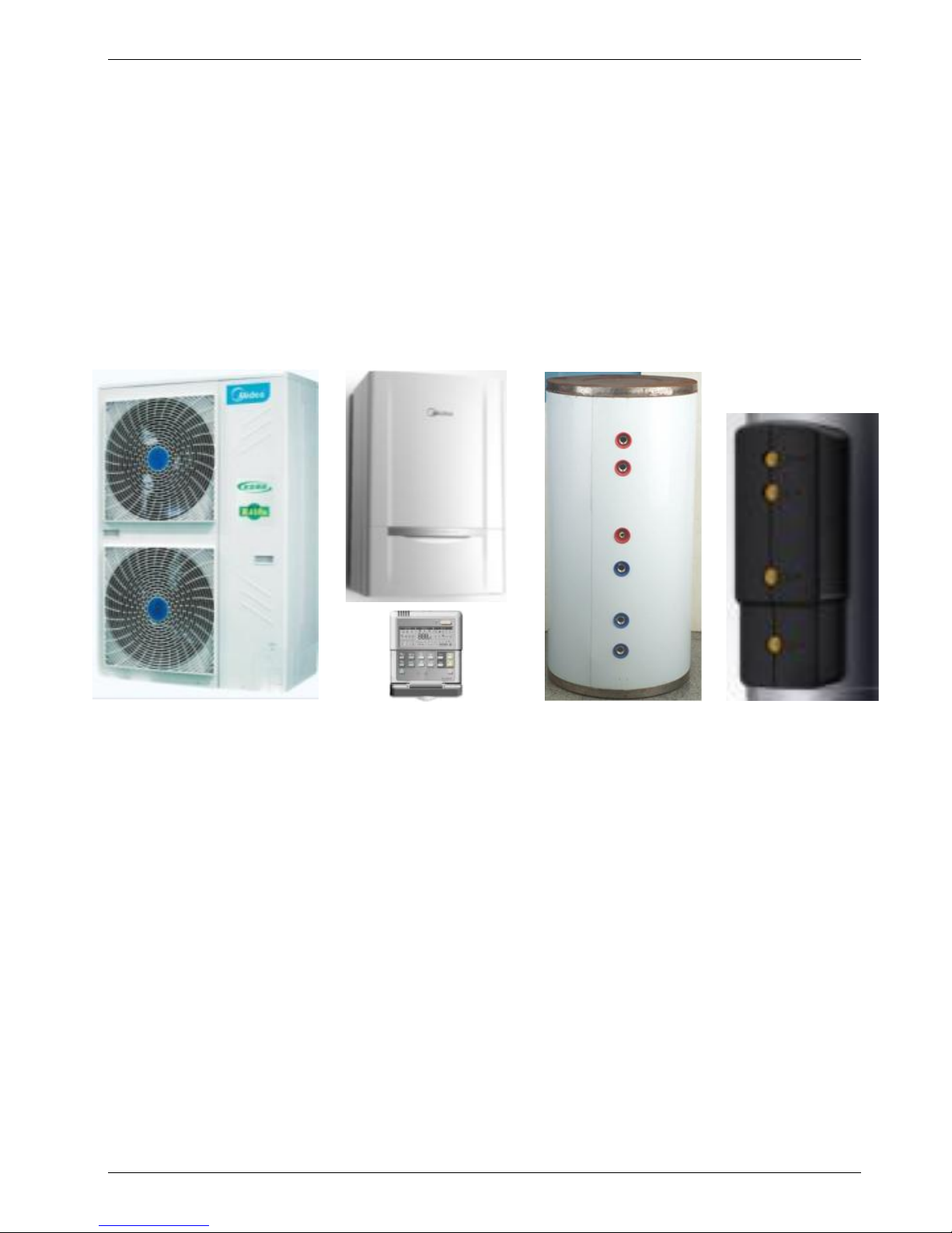
Midea CE-SMK-80/CD30GN1, CE-LRSJF-V100/N1-610, CE-SMK-100/CD30GN1, CE-LRSJF-V60/N1-310, CE-SMK-60/CD30GN1 Technical Manual
...Page 1
MCAC-RTSM-2012-01 M-thermal Technical Manual(part 1)
1
Midea M-thermal
Heat Pump Water Heater
Technical Manual
Midea reserves the right to discontinue, or change at any time, specifications or designs without notices and
without incurring obligations.
CE-LRSJF-V120/N1-610
CE-LRSJF-V100/N1-610
CE-LRSJF-V80/N1-310
CE-LRSJF-V60/N1-310
CE-LRSJF-V80/N1-310-B
Outdoor unit
CE-LSX-300XP/D30B11
CE-LSX-200XP/D30B11
CE-LSX-150XP/D30B7
CE-LSX-300XP/SD15B11
Water tank
CE-SMK-120/CD30GN1
CE-SMK-100/CD30GN1
CE-SMK-80/CD30GN1
CE-SMK-60/CD30GN1
CE-SMK-80/CSD80GN1
Indoor unit
CE-TMK-01
Solar kit
Page 2

MCAC-RTSM-2012-01 M-thermal Technical Manual(part 1)
2
Part 1
System Outline
1. Measurements ................................................................................... 3
2. External Appearance ......................................................................... 4
3. Nomenclature .................................................................................... 5
4. Features ............................................................................................. 7
5. Specifications .................................................................................... 8
5.1 Specifications of outdoor units ............................................................................... 8
5.2 Specifications of Hydraulic indoor unit .................................................................. 9
5.3 Specifications of water tank and solar kit ............................................................ 10
6. Performance data ............................................................................ 11
6.1 Heating performance data of 6/8kw model ........................................................... 11
6.2 Cooling performance data of 6/8kw model .......................................................... 13
6.3 Heating performance data of 10/12kw model ....................................................... 14
6.4 Cooling performance data of 10/12kw model ...................................................... 15
7. Wiring Diagrams .............................................................................. 16
7.1 Outdoor units wiring diagram ............................................................................... 16
7.2 Hydraulic indoor units wiring diagram ................................................................. 18
8. Dimensions ...................................................................................... 20
8.1 Dimensions of outdoor units ................................................................................ 20
8.2 Dimensions of Hydraulic indoor units .................................................................. 21
9. Installation place and service space .............................................. 22
9.1 Outdoor unit service space ................................................................................... 22
9.2 Hydraulic indoor unit installation location and service space ............................ 23
10. Exploded View ........................................................................... 24
10.1 Exploded view of outdoor units ............................................................................ 24
10.2 Exploded view of hydraulic indoor units .............................................................. 28
11. Accessories ............................................................................... 32
12. Functional diagram .................................................................... 33
12.1 Complete system diagram .................................................................................... 33
12.2 Electrical connection diagram and cable specification ...................................... 34
Page 3
MCAC-RTSM-2012-01 M-thermal Technical Manual(part 1)
3
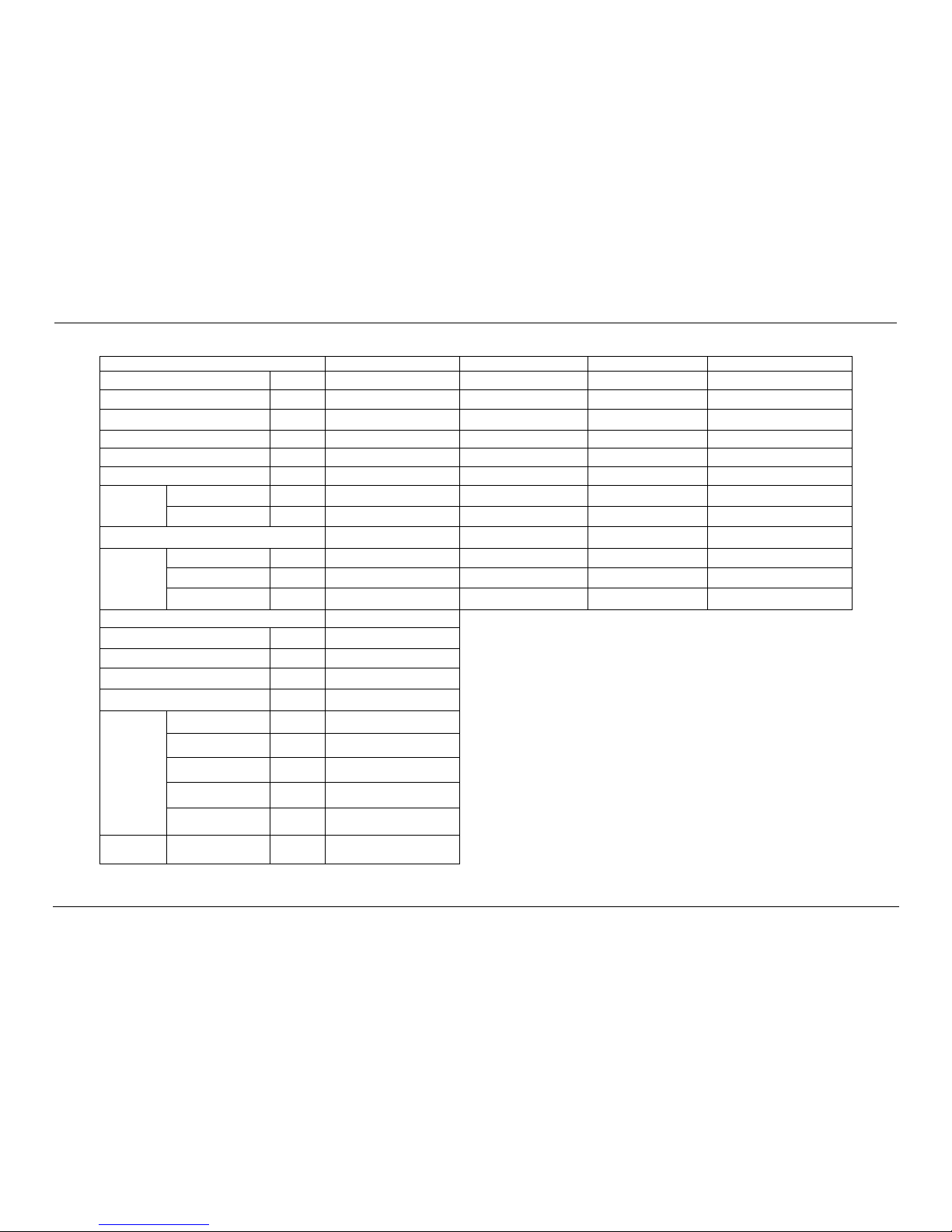
1. Measurements
Outdoor units
Model name
Dimension (mm)
Net/Gross weight (kg)
Power supply
CE-LRSJF-V120/N1-610
Width: 900
Height: 1327
Depth:348
89/101
220~240-50Hz
1 Ph
CE-LRSJF-V100/N1-610
CE-LRSJF-V80/N1-310
Width: 895
Height: 862
Depth:313
66/70
220~240-50Hz
1 Ph
CE-LRSJF-V60/N1-310
CE-LRSJF-V80/N1-310-B
Width: 895
Height: 862
Depth:313
63/67
220~240-50Hz
1 Ph
Hydraulic indoor unit
SMK-120/CD30GN1
Width: 900
Height:500
Depth:375
63/75
220~240-50Hz
1 Ph
SMK-100/CD30GN1
SMK-80/CD30GN1
SMK-60/CD30GN1
SMK-80/CSD80GN1
Width: 900
Height:500
Depth:375
64/77
380V-3Ph-50Hz
Solar kit
CE-TMK-01
Width: 810
Height: 310
Depth:295
8/10
220~240-50Hz
1 ph
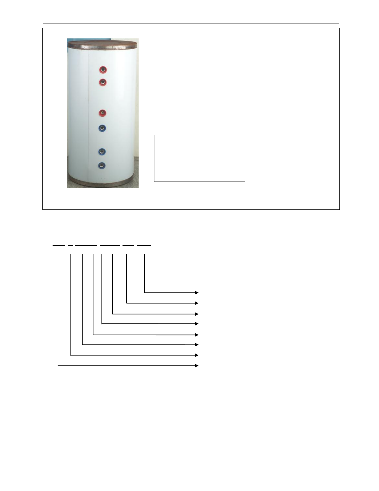
Water Tank
Model name
Dimension (mm)
Net/Gross weight (kg)
Packing Dimension W×D×H
CE-LSX-300XP/D30B11
Ф580×1800
75//84
620×1960×635
CE-LSX-200XP/D30B11
Ф580×1320
60/68
670*1400*670
CE-LSX-150XP/D30B7
Ф580×1055
49/55
670*1135*670
CE-LSX-300XP/SD15B11
Ф580×1800
80/91
670×1885×670
Page 4
MCAC-RTSM-2012-01 M-thermal Technical Manual(part 1)
4
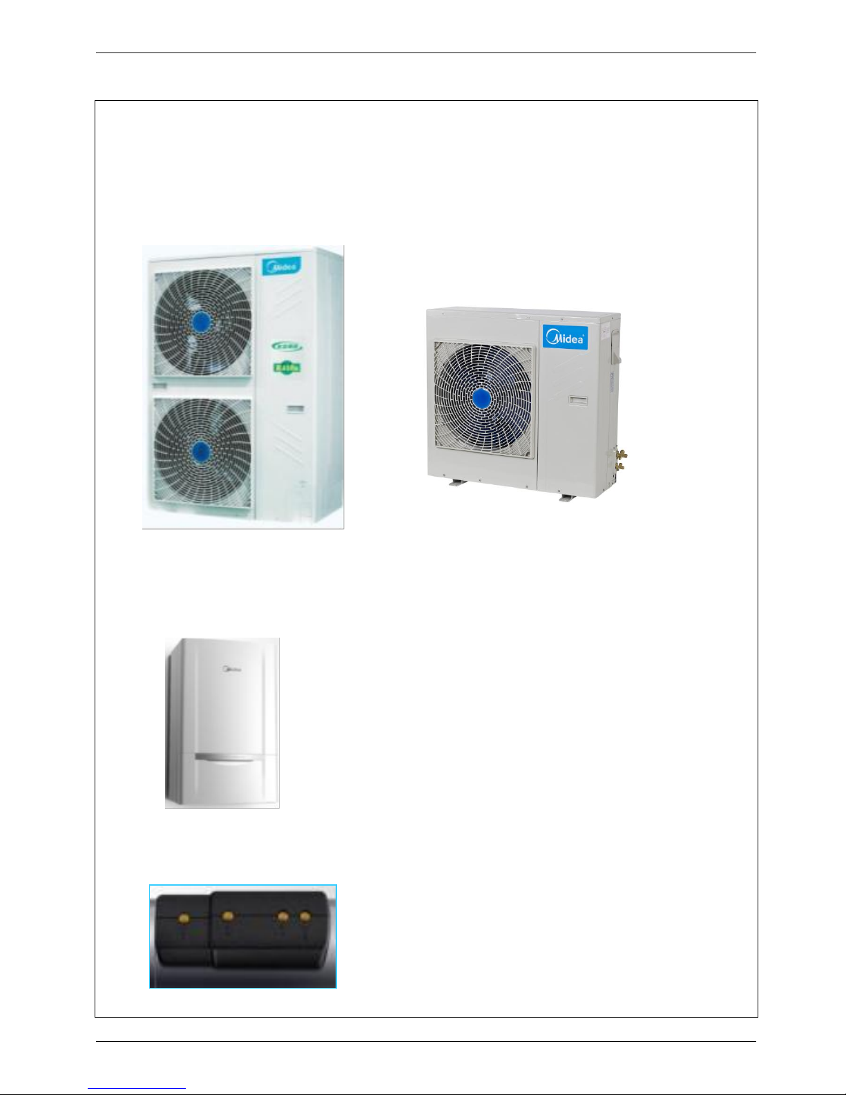
2. External Appearance
CE-LRSJF-V120/N1-610 CE-LRSJF-V80/N1-310
CE-LRSJF-V100/N1-610 CE-LRSJF-V60/N1-310
CE-LRSJF-V80/N1-310-B
CE-SMK-120/CD30GN1 CE-SMK-100/CD30GN1
CE-SMK-80/CD30GN1 CE-SMK-80/CSD80GN1 CE-SMK-60/CD30GN1
CE-TMK-01
Page 5
MCAC-RTSM-2012-01 M-thermal Technical Manual(part 1)
5
3. Nomenclature
Outdoor unit
CE-L RSJF-V100/N1-610
Design code
Refrigerant type (R410a)
Heating Capacity (8000W)
Compressor type (DC compressor)
Split type
Midea Heat Pump water heater
Heating and cooling mode (Omit for heating)
Export model code
CE-LSX-300XP/D30B11
CE-LSX-200XP/D30B11
CE-LSX-150XP/D30B7
CE-LSX-300XP/SD15B11
Page 6
MCAC-RTSM-2012-01 M-thermal Technical Manual(part 1)
6
Indoor unit
CE- SMK – 80 / C S D 80 G N1
Solar kit
CE-TMK-01
CE-L SX-300XP/ D30 B11
Refrigerant type (R410a)
Installation type (Wall-mounted)
E-heater Capacity (8000W)
Electric heater
Power type (3ph, 380V)
Water cycle type
Heating Capacity (8000w)
Hydraulic modular
Export model code
Design code
Solar heating unit
Export model code
Design code
E-heater power(3000w)
Electric heater
Water tank appearance code (spraying appearance)
Water tank inner tank code (Stainless Steel inner tank )
Water tank volume (300L)
Water tank code
Water tank type code (vertical type)
Export model code
Page 7
MCAC-RTSM-2012-01 M-thermal Technical Manual(part 1)
7
4. Features
4.1 Safety
a. Realize isolation between water and electricity. No electric shock problem, more safety.
b. No fuel tubes and storage, no potential danger from oil leakage, fire, explosion etc.
4.2 Five operating model
a. space cooling
b. space heating
c. water heating
d. space cooling + water heating
E. space heating + water heating
1.3 Environmental friendly.
a. R410a refrigerant;
b. No discharge of poisonous gas;
c. Reduce CO2 emission
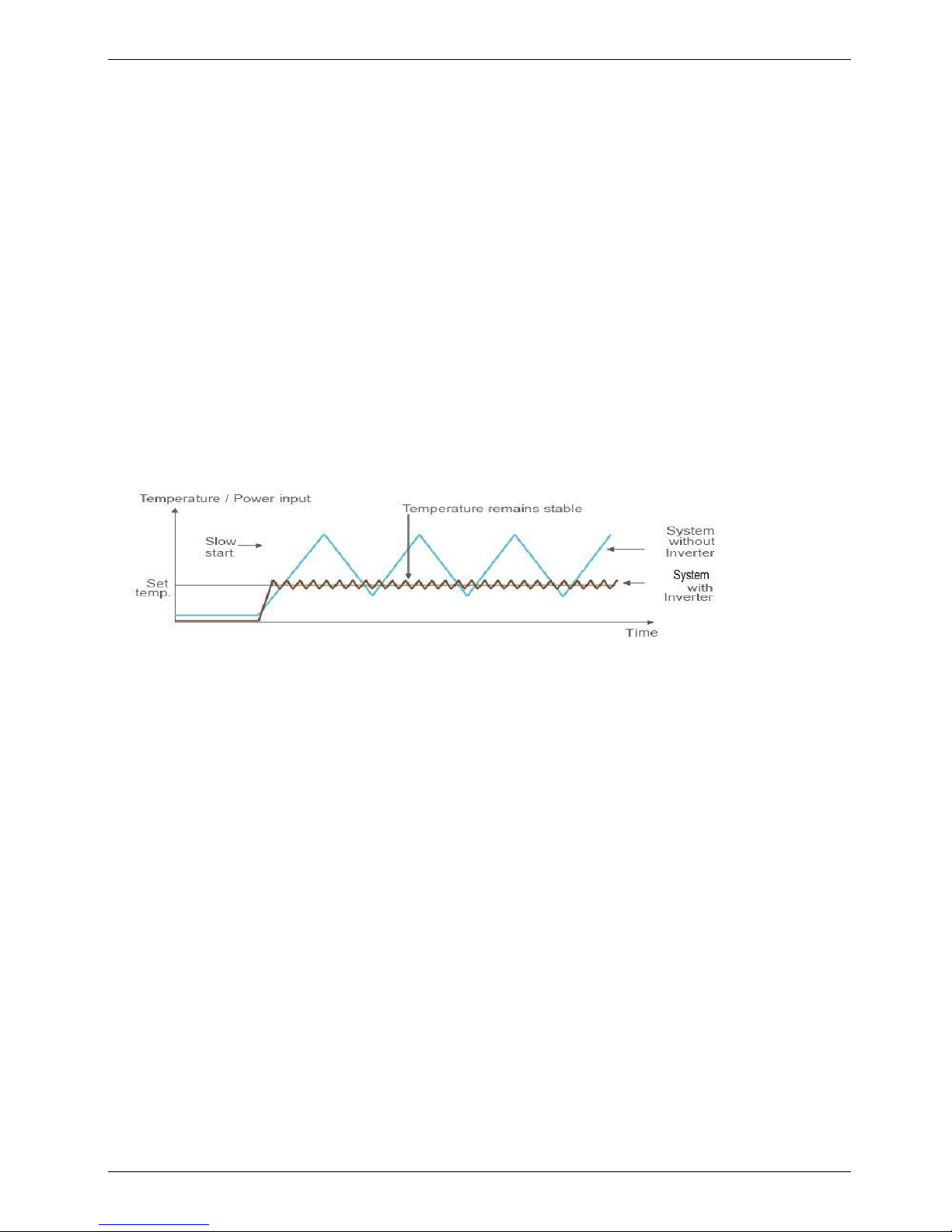
4.4 DC inverter system.
.
4.5 Automatic weekly anti-legionella function
4.6 Easy operation and automatic control.
The system can be controlled simply through the wire controller.
4.7 High efficiency and energy-saving.
The unit adopts heat pump principle, which absorbs heat from outdoor air and produce heat water, thermal
efficiency for water heating be up to 4.3
4.8 All-the-weather running.
Within the temperature range from -20 to 43℃, it will not be affected by night, overcast sky, rain and snow.
4.9 Convenient installation and maintenance
The quadrate type can be easily installed in a corner of the verandah even if it’s very narrow
4.10 Total Heating Solution
When floor heating is conducted in a new house, warm air spreads gently across the house, making it
comfortable and enabling the use of broad space without necessitating radiators or FCU.
4.11 Comfort System
When floor heating is applied, warm air spreads gently across the house, making it comfortable. The system
can help blood circulation and metabolism, further boosting our health.
The installation of M-Thermal will eliminate oil or gas tank, making the household surrounding neat and safe,
enabling the use of more space, and avoiding refueling.
4.11 CE approval
Page 8
MCAC-RTSM-2012-01 M-thermal Technical Manual
8
5. Specifications
5.1 Specifications of outdoor units
DC Inverter outdoor unit
LRSJF-V120/N1-610
LRSJF-V100/N1-610
LRSJF-V80/N1-310
LRSJF-V60/N1-310
LRSJF-V80/N1-310-B
Power supply
Ph-V-Hz
1-220~240-50
1-220~240-50
1-220~240-50
1-220~240-50
1-220~240-50
Max. current
A
23
22
15
14
16
Heating
Capacity
kW
12
10 8 6 8 COP
kW/kW
4.3
4.1
4.08
4.0
4.08
Ambient Temp.
℃
-15~43
-15~43
-15~43
-15~43
-20~43
Cooling
Capacity
kW
9.3
8.5
6.3
6.3
6.3
COP
kW/kW
2.45
2.45
2.23
2.45
2.23
Ambient Temp.
℃
15~43
15~43
15~43
15~43
15~43
Unit
Dimension (W×H×D)
mm
900×1327×348
900×1327×320
895×862×313
895×862×313
895×862×313
Packing (W×H×D)
mm
1016×1456×435
1016×1456×435
1025×910×410
1025×910×410
1025×910×410
Net/gross weight
kg
89/101
89/101
66/70
66/70
63/67
Noise level
dB(A)
58
58
58
58
58
Refrigerant
type/quantity
kg
R410a/2.7kg
R410a/2.7kg
R410a/2.4kg
R410a/2.4kg
R410a/2.4kg
system pressure
MPa
4.4/2.6
4.4/2.6
4.4/2.6
4.4/2.6
4.4/2.6
Compressor
Model
TNB306FPGMC
TNB306FPGMC
TNB220FLHMC
TNB220FLHMC
TNB220FLHMC
Type
Rotary
Rotary
Rotary
Rotary
Rotary
Brand
Mitsubishi
Mitsubishi
Mitsubishi
Mitsubishi
Mitsubishi
Locked rotor current
A
67
67
45
45
45
Rate current
A
13.5
13.5
9.7
9.7
9.7
Crankcase
W
30
30
30
30
30
Capacity
kW
9.8
9.8
7.1
7.1
7.1
Fan motor
Brand
Panasonic
Panasonic
welling
welling
welling
Model
WZDK100-38G(*2)
WZDK100-38G(*2)
YDK75-6H-1
YDK75-6H-1
YDK75-6H-1
Type
DC MOTOR
DC MOTOR
AC MOTOR
AC MOTOR
AC MOTOR
Input w 100*2
100*2
168
168
168
Output
w
110*2
110*2
75
75
75
Speed
r/min
800
800
877/749
877/749
877/749
Max. refrigerant pipe length
m
50
50
25
25
25
Liquid side/ Gas side
mm
Φ9.5/Φ15.9
Φ9.5/Φ15.9
Φ9.5/Φ15.9
Φ9.5/Φ15.9
Φ9.5/Φ15.9
Outdoor coil
Number of rows
2 2 2 2
2
Tube pitch(a)x row
pitch(b)
mm
25.4/22
25.4/22
22*19.05
22*19.05
22*19.05
Tube dia. and type
mm
7.94(female screw)
7.94(female screw)
7.94(female screw)
7.94(female screw)
7.94(female screw)
Page 9
MCAC-RTSM-2012-01 M-thermal Technical Manual
9
Fin space
mm
1.6
1.6
1.7
1.7
1.7
Fin type (code)
Hydrophilic
aluminum
Hydrophilic aluminum
Hydrophilic aluminum
Hydrophilic
aluminum
Hydrophilic aluminum
Coil length x height
1276*870
1276*870
792*38.1
792*38.1
792*38.1
Number of circuits
7 7 8 8
8
Loading
Quantity
20'/40'/40H
Pcs
28/58/58
28/58/58
60/126/126
60/126/126
60/126/126
5.2 Specifications of Hydraulic indoor unit
Hydraulic indoor unit
SMK-120/CD30GN1
SMK-100/CD30GN1
SMK-80/CD30GN1
SMK-60/CD30GN1
SMK-80/CSD80GN1
Power supply
Ph-V-Hz
1-220~240-50
1-220~240-50
1-220~240-50
1-220~240-50
3-380-50
Function
Types
Heating &Cooling
Heating &Cooling
Heating &Cooling
Heating &Cooling
Heating &Cooling
Space Heating
℃
15~55
15~55
15~55
15~55
15~55
Space Cooling
℃
7~22
7~22
7~22
7~22
7~22
Sanitary Hot
Water
℃
35~60
35~60
35~60
35~60
35~60
Max. current
A
27
27
27
27
16
Noise level
dB(A)
32
32
32
32
32
Unit
Dimension
(W×H×D)
mm
900×500×375
900×500×375
900×500×375
900×500×375
900×500×375
Packing
(W×H×D)
mm
1110×610×510
1110×610×510
1110×610×510
1110×610×510
1110×610×510
Net/gross
weight
kg
63/75
63/75
63/75
63/75
64/77
E-heater
Size
kW
1.5
1.5
1.5
1.5
4.5
3.5(spare)
Quantity
2 2 2 2
1
1
Specification
Ph-V
1-220~240
1-220~240
1-220~240
1-220~240
3-380
1-220~240
Water
pipeline
Water inlet
pipe
mm
DN32
DN32
DN32
DN32
DN32
Water outlet
pipe
mm
DN32
DN32
DN32
DN32
DN32
Loading
Quantity
20'/40'/40H
Pcs
66/138/184
66/138/184
66/138/184
66/138/184
66/138/184
The testing Condition:
1. Heating: Outdoor temp. 7/6℃(DB/WB), inlet water temp. 30℃, outlet water temp. 35℃.
2. Cooling: Outdoor temp. 35/24℃(DB/WB), inlet water temp. 12℃, outlet water temp. 7℃.
Page 10
MCAC-RTSM-2012-01 M-thermal Technical Manual
10
5.3 Specifications of water tank and solar kit
Sanitary hot water tank
LSX-300XP/D30B11
LSX-200XP/D30B11
LSX-150XP/D30B7
LSX-300XP/SD15B11
Power supply
Ph-V-Hz
1-220~240-50
1-220~240-50
1-220~240-50
3-380-50
Storage size
L
300
200
150
300
Max. water output temp.
℃
60
60
60
60
Dimension (D×H)
mm
Ф580×1800
Ф580*1320
Ф580×1050
Ф580×1800
Packing (W×H×D)
mm
670×1885×670
670×1400×670
670×1135×670
670×1885×670
Net//gross weight
kg
75/84
60/68
49/55
80/91
E-heater
specification
kW
3.0
3.0
3.0
1.5
Power supply
Ph-V
1-220~240-50
1-220~240-50
1-220~240-50
3-380-50
Tank material
SUS304
SUS304
SUS304
SUS304
Water
pipeline
Water inlet pipe
mm
DN20
DN20
DN20
DN20
Water outlet pipe
mm
DN20
DN20
DN20
DN20
PT valve joint
MPa
DN20
DN20
DN20
DN20
Solar kit
TMK-01
Power supply
Ph-V-Hz
1-220~240-50
Dimension (W×H×D)
mm
810×310×295
Packing (W×H×D)
mm
830×340×315
Net weight
kg
8/10
solar coils
OD+T
mm*mm
¢22*0.8
length
m
11
material
SUS316L
inlet pipe
mm
DN20
outlet pipe
mm
DN20
Loading
Quantity
20'/40'/40H
Pcs
300/624/728
Page 11
MCAC-RTSM-2012-01 M-thermal Technical Manual
11
6. Performance data
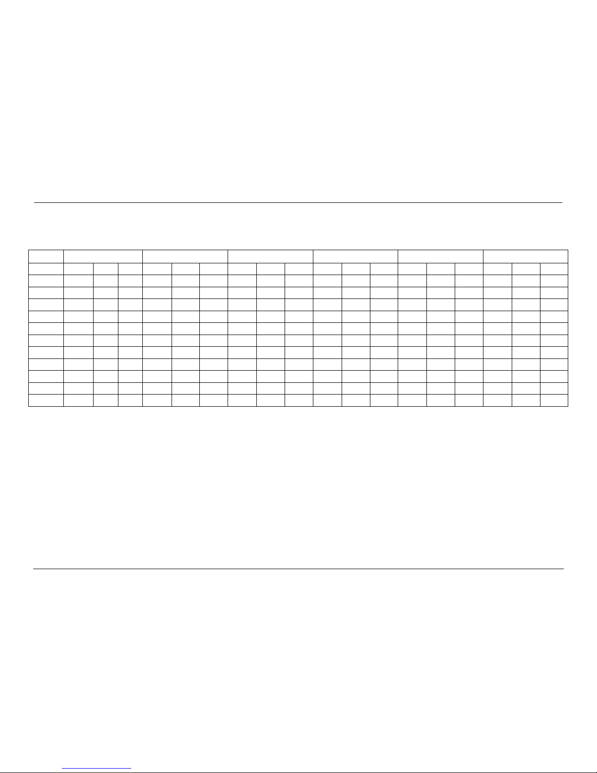
6.1 Heating performance data of 6/8kw model
6kW
LWE[℃]
30
35
40
45
50
55
Tamb [℃]
HC[W]
PI[W]
COP
HC[W]
PI[W]
COP
HC[W]
PI[W]
COP
HC[W]
PI[W]
COP
HC[W]
PI[W]
COP
HC[W]
PI[W]
COP
-15
4877
2206
2.21
4870
2377
2.05
4450
2527
1.76
3410
2543
1.34 / / / / / /
-7
6248
2334
2.68
6057
2490
2.43
5889
2650
2.22
4950
2721
1.82 / / / / / /
0
7576
2281
3.32
7322
2447
2.99
6992
2638
2.65
6354
2707
2.35
4962
2522
1.97 / /
/
2/1
6063
2166
2.80
6536
2401
2.72
6143
2574
2.39
5793
2449
2.37
5064
2525
2.01 / / / 7/6
9551
2360
4.05
9000
2518
3.57
8888
2756
3.22
8262
2841
2.91
6380
2623
2.43
1842
1497
1.23
10/8
9858
2400
4.11
10179
2579
3.95
9745
2753
3.54
8686
2826
3.07
7029
2612
2.69
1681
1466
1.15
15/12
9710
2057
4.72
9357
2215
4.22
9445
2409
3.92
9332
2617
3.57
8247
2678
3.08
3215
1493
2.15
20/15
9560
1940
4.93
9797
2105
4.65
9444
2252
4.19
7486
1978
3.79
5593
1718
3.26
3719
1493
2.49
25/17
10220
1913
5.34
10619
2086
5.09
10742
2276
4.72
9888
2288
4.32
7440
1879
3.96
4274
1477
2.96
30/22
11407
1889
6.04
11896
2069
5.75
12026
2267
5.31
11906
2471
4.82
7266
1717
4.23
4013
1409
2.85
35/24 / / / / / /
12652
2184
5.79
12630
2479
5.10
6775
1634
4.15
3820
1433
2.67
Remark:
HC = heating capacity PI = power input
Page 12

MCAC-RTSM-2012-01 M-thermal Technical Manual
12
8kW
LWE[℃]
30
35
40
45
50
55
Tamb [℃]
HC[W]
PI[W]
COP
HC[W]
PI[W]
COP
HC[W]
PI[W]
COP
HC[W]
PI[W]
COP
HC[W]
PI[W]
COP
HC[W]
PI[W]
COP
-15
5186
2322
2.23
5178
2502
2.07
4731
2660
1.78
3626
2677
1.35 / / / / / /
-7
6643
2457
2.7
6440
2621
2.46
6262
2789
2.25
5263
2864
1.84 / / / / / / 0 8055
2401
3.35
7785
2576
3.02
7434
2777
2.68
6756
2849
2.37
5276
2655
1.99 / / / 2/1
6512
2280
2.86
7020
2527
2.78
6598
2709
2.44
6222
2578
2.41
5439
2658
2.05 / /
/
7/6
10155
2484
4.09
9569
2650
3.61
9450
2901
3.26
8785
2991
2.94
6784
2761
2.46
1959
1576
1.24
10/8
10482
2526
4.15
10823
2715
3.99
10362
2898
3.58
9236
2975
3.1
7474
2749
2.72
1987
1543
1.29
15/12
10324
2165
4.77
9949
2332
4.27
10042
2536
3.96
9922
2755
3.6
8769
2819
3.11
3418
1572
2.17
20/15
10165
2042
4.98
10417
2216
4.7
10041
2371
4.23
7960
2082
3.82
5947
1808
3.29
3954
1572
2.52
25/17
10867
2014
5.4
11291
2196
5.14
11422
2396
4.77
10514
2408
4.37
7911
1978 4 4651
1555
2.99
30/22
12007
2008
5.98
12522
2200
5.69
12659
2410
5.25
12533
2627
4.77
7648
1826
4.19
4224
1498
2.82
35/24 / / / / / /
13452
2299
5.85
13429
2609
5.15
7204
1720
4.19
4062
1508
2.7
Remark:
HC = heating capacity PI = power input
Page 13
MCAC-RTSM-2012-01 M-thermal Technical Manual
13
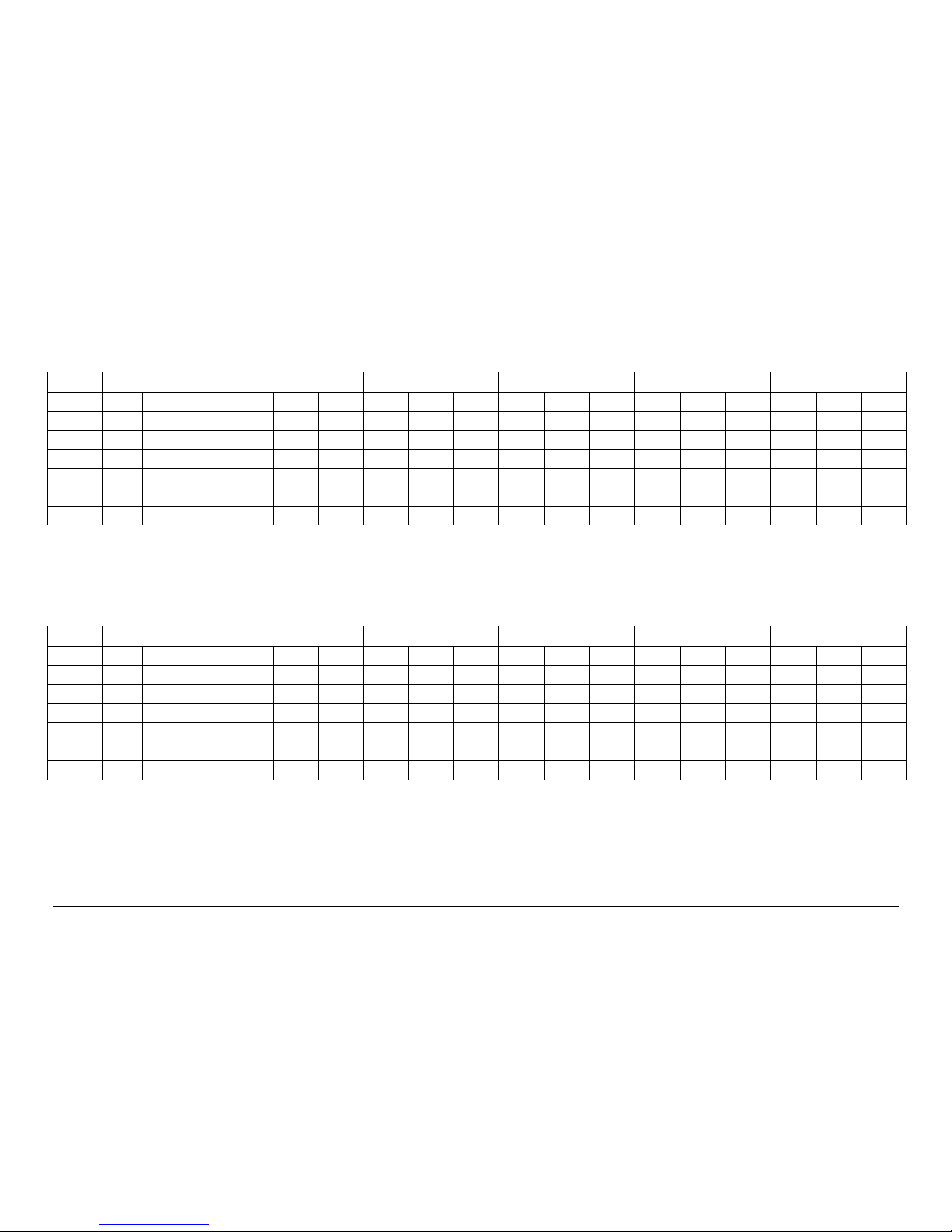
6.2 Cooling performance data of 6/8kw model
6kW
LWE[℃]
7
10
13
15
18
22
Tamb [℃]
CC[W]
PI[W]
EER
CC[W]
PI[W]
EER
CC[W]
PI[W]
EER
CC[W]
PI[W]
EER
CC[W]
PI[W]
EER
CC[W]
PI[W]
EER
20
7033
1771
3.97
8800
2066
4.26
8903
2046
4.35
9973
2263
4.41 / / / / / /
25
6917
2060
3.36
6362
1560
4.08
8380
2219
3.78
9896
2398
4.13
11436
2913
3.93
12605
2924
4.31
30
6146
1959
3.14
6367
1980
3.22
8337
2508
3.32
9226
2590
3.56
10853
3084
3.52
11933
3181
3.75
35
3714
1524
2.44
6468
2656
2.43
7122
2718
2.62
8406
3164
2.66
9901
3372
2.94
10615
3432
3.09
40 / / / 4767
2243
2.13
5452
2292
2.38
5955
2327
2.56
6755
2369
2.85
8058
2434
3.31
43 / / / 3858
2072
1.86
4596
2106
2.18
4956
2134
2.32
5724
2173
2.63
6859
2224
3.08
Remark:
CC= cooling capacity PI = power input
8kW
LWE[℃]
7
10
13
15
18
22
Tamb [℃]
CC[W]
PI[W]
EER
CC[W]
PI[W]
EER
CC[W]
PI[W]
EER
CC[W]
PI[W]
EER
CC[W]
PI[W]
EER
CC[W]
PI[W]
EER
20
7151
1802
3.97
8838
2106
4.2
8982
2081
4.32
10081
2328
4.33 / / / / / /
25
7205
2147
3.36
6627
1631
4.06
8729
2328
3.75
10308
2502
4.12
11912
3052
3.9
13130
3057
4.30
30
6402
2061
3.11
6632
2083
3.18
8684
2639
3.29
9610
2725
3.53
11305
3245
3.48
12430
3347
3.71
35
3869
1604
2.41
6737
2795
2.41
7419
2860
2.59
8756
3329
2.63
10314
3548
2.91
11057
3611
3.06
40 / / / 4966
2360
2.1
5679
2412
2.35
6203
2448
2.53
7036
2493
2.82
8394
2561
3.28
43 / / / 4019
2180
1.84
4787
2216
2.16
5162
2245
2.3
5963
2286
2.61
7145
2340
3.05
Remark:
CC= cooling capacity PI = power input
Page 14
MCAC-RTSM-2009-09 Midea Heat Pump Water Heater Technical Manual
14
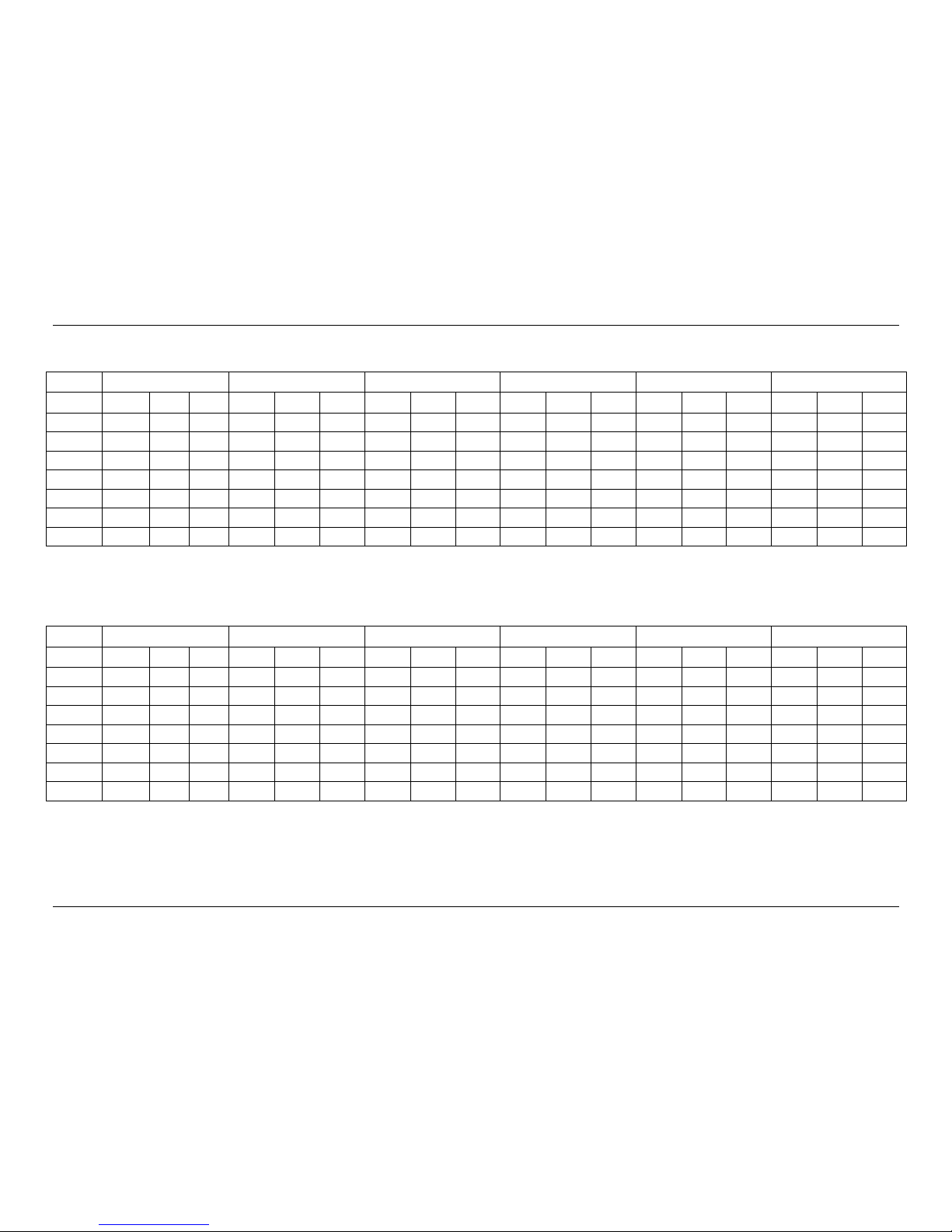
6.3 Heating performance data of 10/12kw model
10kW
LWE[℃]
30
35
40
45
50
55
Tamb [℃]
HC[W]
PI[W]
COP
HC[W]
PI[W]
COP
HC[W]
PI[W]
COP
HC[W]
PI[W]
COP
HC[W]
PI[W]
COP
HC[W]
PI[W]
COP
-15
6912
3245
2.13
4619
3009
1.54
5931
3671
1.62
/ / / / / / / / /
-7
8616
3198
2.69
8173
3306
2.47
7551
3598
2.10
5237
3436
1.52
4433
3625
1.22
/ / /
0
10548
3330
3.17
10125
3353
3.02
9355
3574
2.62
10523
4058
2.59
6178
3471
1.78
5245
3606
1.45
2/1
8274
3300
2.51
8855
3185
2.78
9408
3580
2.63
7879
3556
2.22
6622
3530
1.88
5624
3670
1.53
7/6
13655
3366
4.06
11638
2901
4.01
11969
3710
3.23
11097
3966
2.80
8702
3679
2.37
7008
3870
1.81
20/15
13178
2153
6.12
11738
2279
5.15
12980
2591
5.01
10033
2477
4.05
8931
2506
3.56
7399
2682
2.76
35/24
14856
2066
7.19
18012
2594
6.94
14247
2506
5.69
14095
2411
5.85
9143
2471
3.70
9197
2260
4.07
Remark:
HC = heating capacity PI = power input
12kW
LWE[℃]
30
35
40
45
50
55
Tamb [℃]
HC[W]
PI[W]
COP
HC[W]
PI[W]
COP
HC[W]
PI[W]
COP
HC[W]
PI[W]
COP
HC[W]
PI[W]
COP
HC[W]
PI[W]
COP
-15
7198
3345
2.15
4810
3102
1.55
6176
3785
1.63 / / / / / / / / / -7
8972
3297
2.72
8511
3408
2.50
7863
3709
2.12
5454
3542
1.54
4616
3737
1.24 / / / 0
10984
3433
3.20
10354
3395
3.05
9742
3685
2.64
10958
4184
2.62
6433
3578
1.80
5462
3718
1.47
2/1
8616
3402
2.53
9221
3283
2.81
9797
3691
2.65
8205
3666
2.24
6896
3639
1.90
5857
3784
1.55
7/6
13932
3400
4.10
11874
2930
4.05
12212
3747
3.26
11322
4006
2.83
8879
3716
2.39
7150
3909
1.83
20/15
13446
2175
6.18
11976
2302
5.20
13244
2617
5.06
10237
2502
4.09
9112
2531
3.60
7549
2709
2.79
35/24
15638
2283
6.85
18325
2756
6.65
14536
2531
5.74
14381
2435
5.91
9329
2496
3.74
9384
2283
4.11
Remark:
HC = heating capacity PI = power input
Page 15
MCAC-RTSM-2009-09 Midea Heat Pump Water Heater Technical Manual
15
6.4 Cooling performance data of 10/12kw model
10kW
LWE[℃]
7
10
13
15
18
22
Tamb
[℃]
CC[W]
PI[W]
EER
CC[W]
PI[W]
EER
CC[W]
PI[W]
EER
CC[W]
PI[W]
EER
CC[W]
PI[W]
EER
CC[W]
PI[W]
EER
20
5498
1250
4.40
9412
2070
4.55
12005
2230
5.38
12906
2539
5.08
14468
2979
4.86
15310
2908
5.26
25
5024
1072
4.69
11458
2742
4.18
11116
3044
3.65
13584
3060
4.44
14486
3295
4.40
17194
3497
4.92
30
7699
2437
3.16
10710
3003
3.57
12601
3319
3.80
13185
3342
3.95
14289
3533
4.04
16444
3772
4.36
35
4020
1372
2.93
10149
3593
2.83
11732
3680
3.19
12369
3715
3.33
13646
3913
3.49
15725
4191
3.75
40
6278
2938
2.14
8345
3468
2.41
9439
3549
2.66
10306
3596
2.87
11478
3662
3.13
13126
3740
3.51
43
5872
3017
1.95
7170
3350
2.14
8334
3419
2.44
9104
3471
2.62
10059
3526
2.85
11683
3603
3.24
Remark:
CC= cooling capacity PI = power input
12kW
LWE[℃] 7 10
13
15
18
22
Tamb
[℃]
CC[W]
PI[W]
EER
CC[W]
PI[W]
EER
CC[W]
PI[W]
EER
CC[W]
PI[W]
EER
CC[W]
PI[W]
EER
CC[W]
PI[W]
EER
20
5668
1289
4.40
9703
2134
4.55
12376
2299
5.38
13305
2618
5.08
14915
3071
4.86
15783
2998
5.26
25
5127
1094
4.69
11692
2798
4.18
11343
3106
3.65
13861
3122
4.44
14782
3362
4.40
17545
3568
4.92
30
7856
2487
3.16
10929
3064
3.57
12858
3387
3.80
13454
3410
3.95
14581
3605
4.04
16780
3849
4.36
35
4061
1386
2.93
10252
3629
2.83
11851
3717
3.19
12494
3753
3.33
13784
3953
3.49
15884
4233
3.75
40
6341
2968
2.14
8429
3503
2.41
9534
3585
2.66
10410
3632
2.87
11594
3699
3.13
13259
3778
3.51
43
5931
3047
1.95
7242
3384
2.14
8418
3454
2.44
9196
3506
2.62
10161
3562
2.85
11801
3639
3.24
Remark:
CC= cooling capacity PI = power input
Page 16
MCAC-RTSM-2009-09 Midea Heat Pump Water Heater Technical Manual
16
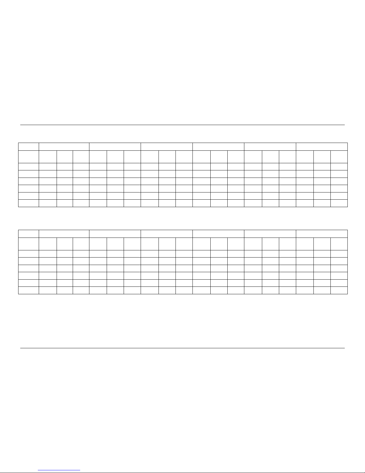
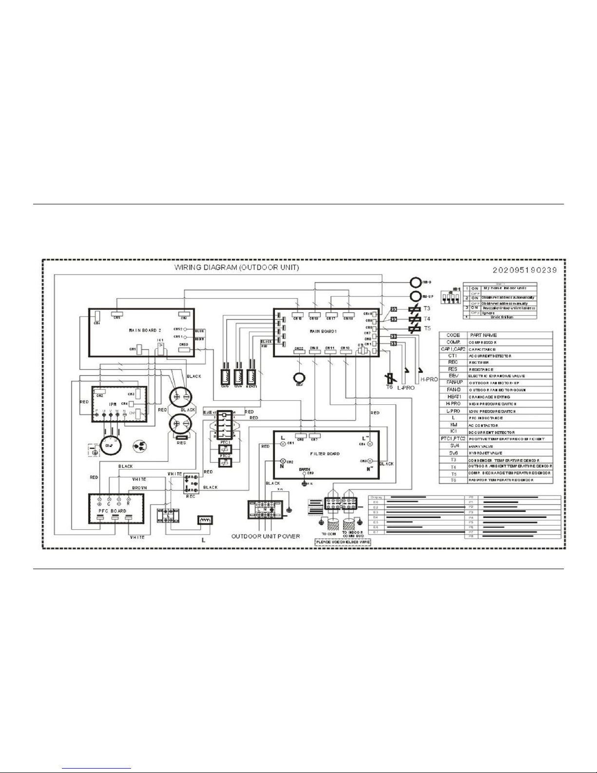
7. Wiring Diagrams
7.1 Outdoor units wiring diagram
Model:CE-LRSJF-V120/N1-610 CE-LRSJF-V100/N1-610
Page 17
MCAC-RTSM-2009-09 Midea Heat Pump Water Heater Technical Manual
17
Model:CE-LRSJF-V60/N1-310 CE-LRSJF-V80/N1-310 CE-LRSJF-V80/N1-310-B
Page 18
MCAC-RTSM-2009-09 Midea Heat Pump Water Heater Technical Manual
18
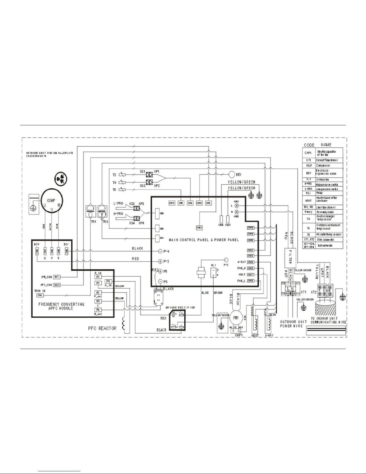
7.2 Hydraulic indoor units wiring diagram
Model :SMK-120/CD30GN1 SMK-100/CD30GN1 SMK-80/CD30GN1 SMK-60/CD30GN1
Page 19

MCAC-RTSM-2009-09 Midea Heat Pump Water Heater Technical Manual
19
Model :SMK-80/CSD80GN1
Page 20

MCAC-RTSM-2009-09 Midea Heat Pump Water Heater Technical Manual
20
8. Dimensions
8.1 Dimensions of outdoor units
Model: CE-LRSJF-V120/N1-610 CE-LRSJF-V100/N1-610
Model: CE-LRSJF-V80/N1-310 CE-LRSJF-V60/N1-310 CE-LRSJF-V80/N1-310-B
Page 21

MCAC-RTSM-2009-09 Midea Heat Pump Water Heater Technical Manual
21
8.2 Dimensions of Hydraulic indoor units
Model :SMK-120/CD30GN1 SMK-100/CD30GN1 SMK-80/CD30GN1 SMK-60/CD30GN1
SMK-80/CSD80GN1
Page 22

MCAC-RTSM-2009-09 Midea Heat Pump Water Heater Technical Manual
22
9. Installation place and service space
9.1 Outdoor unit service space
a) Selecting an installation location
A place which provides a specified space around the outdoor unit.
A place were the operation noise and discharged air are not given(affected) to your neighbors.
A place that is not exposed to a strong wind.
A place that does not block a passage.
When the outdoor unit is installed in an elevated position, be sure to secure its feet.
There must be sufficient space for carrying in the unit.
A place where the drain water does not make any problem
b) Single unit service place
c) Parallel connect the two units or above
d) Parallel connect the front with rear sides
Page 23

MCAC-RTSM-2009-09 Midea Heat Pump Water Heater Technical Manual
23
9.2 Hydraulic indoor unit installation location and service space
a) Selecting an installation location
The indoor unit should be installed in a water proof place, or the safety of the unit and the operator cannot
be ensured.
The indoor unit is to be wall mounted in an indoor location that meets the following requirements:
The installation location is frost-free.
The space around the unit is adequate for service.
The space around the unit allows for sufficient air circulation.
There is a provision for condensate drain and pressure relief valve blow off.
All piping lengths and distance have been taken into consideration.
Requirement
SMK-120/CD30GN1
SMK-100/CD30GN1
SMK-80/CD30GN1
SMK-60/CD30GN1
Maximum allowable refrigerant piping length between outdoor unit
and indoor unit.
50m
25m
Maximum allowable height distance between outdoor
unit and indoor unit when outdoor unit is top.
15m
10m
Maximum allowable height distance between outdoor
unit and indoor unit when outdoor unit is bottom
10m
5m
Maximum allowable distance between the 2-way valve SV1 and
the indoor unit (only for installations with sanitary hot water tank).
3m
3m
Maximum allowable distance between the sanitary hot water tank
and the indoor unit (only for installations with sanitary hot water
tank). The thermistor cable supplied with the indoor unit is 15 min
length.
10m
10m
Maximum allowable be distance between the T1B and the indoor
unit .The temperature sensor cable of T1B supplied with the indoor
unit is 10m in length.
8m
8m
The equipment is not intended for use in a potentially explosive atmosphere.
b) Service space
Page 24

MCAC-RTSM-2009-09 Midea Heat Pump Water Heater Technical Manual
24
10. Exploded View
10.1 Exploded view of outdoor units
Model: CE-LRSJF-V120/N1-610 CE-LRSJF-V100/N1-610
Page 25

MCAC-RTSM-2009-09 Midea Heat Pump Water Heater Technical Manual
25
No.
Part Name
No.
Part Name
1
E-part box ass'y
7
room temp sensor ass'y
1.1
Outdoor control board assembly
8
Condenser components
1.2
Capacitor card
9
Handle
1.3
Wire joint
10
Cover before the tube
1.4
Outdoor power board assembly
11
After the tube cover
1.5
Resistance
13
Four-way valve parts
1.6
wire clamp
14
Suction pipe ass'y
1.7
Contactor
14.1
Pressure controller
1.8
Inverter module
14.2
Capillary ass'y
1.9
Three phase bridge
15
Compressor discharge tube assembly
1.10
Six Terminal Block
15.1
Oil separator
1.11
Electrical mounting plate Ⅱ
15.2
Strainer
1.12
Discharge temp sensor ass'y
16
Discharge temp sensor ass'y
1.13
Welding pieces of electrical box
17
Expansion valve ass'y
1.14
Rubber ring
17.1
Electronic expansion valve
1.15
Radiator
17.2
EEV solenoid
1.16
Aluminum electro analysis capacitor
17.3
Low pressure valve
1.17
Active PFC module components
18
Gas-liquid separator
1.18
Main control board ass'y
19
Valve mounting plate
1.19
Electrical mounting plate Ⅰ
20
gas-liquid separator plate
1.20
pieces of electrical box
21
Front Panel
2
Inductance box components
22
Grille ass'y
2.1
Inductor lid welding parts
23
Left rear support
2.2
Plate welding pieces of the wind
24
Layering fence
2.3
PFC Inductor
25
Compressor electric heater
2.4
Inductor mounting plate
26
Partition components
3
Compressor
27
Axial fan
4
Temp sensor ass'y
28
DC Motor
5
Right front side components
29
Cover parts
6
Right rear side
30
Motor bracket assembly
7
Room temp sensor ass'y
31
Chassis welding parts
Page 26

MCAC-RTSM-2009-09 Midea Heat Pump Water Heater Technical Manual
26
Model: CE-LRSJF-V60/N1-310 CE-LRSJF-V80/N1-310 CE-LRSJF-V80/N1-310-B
Page 27

MCAC-RTSM-2009-09 Midea Heat Pump Water Heater Technical Manual
27
No.
Part Name
No.
Part Name
1
Top cover ass'y
9
4-way valve ass'y
2
E-part box ass'y
9.1
Pressure controller
2.1
Main control board ass'y
9.2
Low pressure valve
2.2
Inverter module
9.3
Oil separator
2.3
EMC filter
9.4
Solenoid
2.4
Rectifier
9.5
4-way valve
2.5
PFC inductance
10
Suction pipe ass'y
2.6
Wire joint
10.1
Pressure controller
2.7
Wire joint
11
Accumulator cylinder
2.8
Motor capacitor
12
Compressor
3
Rear right clapboard ass'y
13
Base ass'y
4
Handle
14
Partition board ass'y
5
Big handle ass'y
15
Axial flow fan
6
High pressure valve ass'y
16
Motor
6.1
Strainer
17
Grille ass'y
6.2
High pressure valve
18
Motor bracket ass'y
6.3
EEV solenoid
19
Front panel
6.4
Electronic expansion valve body
20
Condenser ass'y
7
Valve plate
21
Left holder
8
Front clapboard ass'y
22
plate frame
Page 28

MCAC-RTSM-2009-09 Midea Heat Pump Water Heater Technical Manual
28
10.2 Exploded view of hydraulic indoor units
Model :SMK-120/CD30GN1 SMK-100/CD30GN1 SMK-80/CD30GN1 SMK-60/CD30GN1
Page 29

MCAC-RTSM-2009-09 Midea Heat Pump Water Heater Technical Manual
29
No.
Part Name
No.
Part Name
1
Bottom
18
Outlet pipe fixed plate
2
Flip
19
Right foam refrigerant pipe
3
Decorative ring
20
Target flow switch
4
Decorative plates
21
Left foam refrigerant pipe
5
Magnet sets
22
Right out of the bubble pipe
6
Roof
23
Left out of the bubble pipe
7
Front Panel
24
Electronic box mounting plate
8
E-part box ass'y
25
Electronic box mounting plate
8.1
Main control board ass'y
26
Water tray components
8.2
Wire joint, 6p
27
Connect hose
8.3
AC contactor
28
Safety valve
8.4
Transformer
29
Electric heating pipe water
8.5
Wire joint, 6p
30
Exhaust valve
8.6
Wire joint
31
Small water tank
8.7
32A MCB
32
Outlet pipe components
8.8
Thirty Terminal Block
33
Expansion Tank
9
Electronic control box cover
34
Electric valve
10
Rear
35
Wired remote support
11
Casing components
36
Electric heating cover
11.1
Liquid tube assemblies
37
Pump Bracket 2
11.2
Tracheal components
38
Pump bracket
11.3
Inlet components
39
Hydraulic module wired remote
11.4
Pipe heat exchanger
40
Expansion Tank
12
Pump mounting plate
41
Pipe temperature sensor ass'y
13
Handle
42
Small water tank fixed plate
14
Refrigerant pipe fixed plate
43
Temp sensor
15
Mounting Bracket
44
Thermostat components
16
Fixed plate inlet
45
Drain Pump
17
Expansion tank clamp
46
Hydraulic meter
Page 30

MCAC-RTSM-2009-09 Midea Heat Pump Water Heater Technical Manual
30
Model : SMK-80/CSD80GN1
Page 31

MCAC-RTSM-2009-09 Midea Heat Pump Water Heater Technical Manual
31
No.
Part Name
No.
Part Name
1
Bottom
18
Outlet pipe fixed plate
2
Flip
19
Right foam refrigerant pipe
3
Decorative ring
20
Target flow switch
4
Decorative plates
21
Left foam refrigerant pipe
5
Magnet sets
22
Right out of the bubble pipe
6
Roof
23
Left out of the bubble pipe
7
Front Panel
24
Electronic control box mounting plate
8
E-part box ass'y
25
Electronic control box mounting plate
8.1
Main control board ass'y
26
Water tray components
8.2
Wire joint, 6p
27
Connect hose
8.3
32A MCB
28
Safety valve
8.4
AC contactor
29
Electric water heating tube
8.5
Transformer
30
Exhaust valve
8.6
Wire joint, 5p
31
Small water tank
8.8
E-part box ass'y
32
Outlet pipe components
8.9
Thirty Terminal Block
33
Expansion Tank
8.10
Contactor
34
Electric valve
8.11
Wire joint
35
Wired remote support
9
Electronic control box cover
36
Electric heating cover
10
Rear
37
Pump Bracket 2
11
Casing components
38
Pump bracket
11.1
Inlet components
39
Hydraulic module wired remote
11.2
Tracheal components
40
Expansion Tank take over the components
11.3
Tube heat exchanger
41
Pipe temperature sensor assemblies
11.4
Liquid tube assemblies
42
Small water tank fixed plate
12
Pump mounting plate
43
Temp sensor
13
Handle
44
Thermostat components
14
Refrigerant pipe fixed plate
45
Drain Pump
15
Mounting Bracket
46
Hydraulic meter
16
Fixed plate inlet
47
Manual ball valve
17
Expansion tank clamp
Page 32

MCAC-RTSM-2009-09 Midea Heat Pump Water Heater Technical Manual
32
11. Accessories
Unit
Name
Sharp
Quantity
Outdoor
Unit
Accessories
Outdoor unit
installation manual
1
Outdoor unit
Owner’s manual
1
Outflow
connecting tube
1
Waterproof rubber cap
1
Hydraulic
Indoor
Unit
Accessories
Owner's & Installation
Manual
1
Mounting bracket
1
Two-way valve
3
M4 screws
2
Water tank temperature sensor
1
Y-sharp filter
1
Floor heating inlet
temperature sensor, T1B
1
Drain pan kit
1
M8 expansion screws
5
Solar
Kit
Accessories
Installation & Owner’s
Manual
1
adapter
2
Sealing
6
Screws
2
Washer
2
Water
Tank
Accessories
Owner’s & Installation
Manual
1
Y-shaped Filter
1
One Way Valve
1
Page 33

MCAC-RTSM-2009-09 Midea Heat Pump Water Heater Technical Manual
33
12. Functional diagram
12.1 Complete system diagram
NO
Name
NO
Name
NO
Name
1
Outdoor unit
13
By-pass valve (field supply)
25
Solar kit (optional)
2
Indoor unit (Hydro kit)
14
By-pass valve (field supply)
26
Pump for solar kit, Pump 3
3
Refrigerant to water heat
exchanger
15
Collector (field supply)
27
Non-return valve
4
Auxiliary heater vessel
16
Motorized 2-way valve SV3
28
Pump for solar pump station
5
Pump 1
17
Motorized 2-way valve SV1
29
Solar pump station (field supply)
6
Shut-off valve (field supply)
18
Water to water heat exchanger
30
Solar panels (field supply)
7
Auxiliary pump(optional, field
supply)
19
Shut-off valve (field supply)
31
Temperature sensor for
heating/cooling water
8
Water to water heat exchanger
kit
20
Sanitary hot water tank
32
Temperature sensor for sanitary
water T5
9
Boiler (optional, field supply)
21
Electric heater
33
Non-return valve (field supply)
10
Pump 4 (optional, field supply)
22
Non-return valve
34
Non-return valve (field supply)
11
Motorized 2-way valve SV2
23
Non-return valve
35
Y-sharp filter
12
Collector (field supply)
24
Water to water heat exchanger
Page 34

MCAC-RTSM-2009-09 Midea Heat Pump Water Heater Technical Manual
34
12.2 Electrical connection diagram and cable specification
cable specification
NO
Description
Require number of
core
Section of the conductor
1
Power supply cable for indoor unit
2 or 3+GND
2.5 mm2
2
Power supply cable for electric heater
2 or 3+GND
2.5 mm2
3
Temperature sensor cable
2
—
4
Power supply cable from indoor unit to Sanitary
hot water tank
2 or 3+GND
2.5 mm2
5
Power supply cable for Pump of solar kit (Pump
3)
2+GND
1.0 mm2
6
Power supply cable for motorized 2-way valve,
SV3
3
1.0 mm2
7
Power supply cable for motorized 2-way -valve,
SV2
3
1.0 mm2
8
Power supply cable for motorized 2-way valve,
SV1
3
1.0 mm2
9
Power supply cable for auxiliary pump (Pump2)
2+GND
1.0 mm2
10
Communication cable between indoor unit and
boiler
2
1.0 mm2
11
Room thermostat cable
4(L, N, C, H)
1.0 mm2
12
Communication cable between indoor unit and
outdoor unit
3 (P, Q, E)
3×0.5 mm2
(3 -Shield wire)
13
Power supply cable for outdoor unit
2+GND
4.0 mm2
14
Power supply cable for solar pump station
2+GND
1.0 mm2
15
Power supply cable for the pump of solar kit
2+GND
1.0 mm2
16
Signal input from solar pump station to indoor
unit
2
1.0 mm2
17
Power supply cable for the pump of solar kit
2+GND
1.0 mm2
18
Sanitary hot water tank temperature sensor
cable
2
—
19
Sanitary hot water tank temperature sensor
cable
2
—
20
Water circuit temperature senor T1B cable
2
—
Page 35

MCAC-RTSM-2012-01 M-thermal Technical Manual (part 2)
Part 2 trouble shooting
1. Normal Phenomenon ................................................................................................................................................ 2
2. M-thermal system protection in Common ........................................................................................................... 3
3. Trouble and causes of heat pump ......................................................................................................................... 3
4. Malfunction Code and Troubleshooting ............................................................................................................... 4
4.1 Outdoor unit malfunction Code and troubleshooting .......................................................................... 4
A. "E0": Outdoor unit EEPROM malfunction ...................................................................................... 5
B. "E2": Communication error of the outdoor chip and the indoor chip ............................................. 6
C. "E3": Communication error of outdoor chip and DSP ................................................................... 7
D. "E4": Outdoor temperature sensor error ............................................................................................... 8
E. "E5": Voltage protection error ................................................................................................................. 9
F. "E6": Direct-current fan error ................................................................................................................ 10
G. "P1": High pressure protection .................................................................................................... 11
H. "P2": Low pressure protection ..................................................................................................... 12
4.2 Hydraulic indoor unit malfunction Code and trouble shooting ....................................................... 13
A. "E0" "E8": Flow switch error ........................................................................................................ 14
B. “E1 E3 E4 E5 E6 E7 E8 E9 EA Eb”: Temperature sensor error .................................................. 15
C. "E2": UI communication error ...................................................................................................... 16
Page 36

MCAC-RTSM-2012-01 M-thermal Technical Manual (part 2)
1. Normal Phenomenon
1.1 The heat pump does not start immediately after the ON/OFF button on the
remote controller is pressed.
If the operation lamp lights, the system is in normal condition. To prevent overloading of the compressor
motor, the heat pump starts 3 minutes after it is turned ON.
If the operation lamp and the "PRE-DEF indicator (cooling and heating type) or fan only indicator (cooling
only type)" light, it means you choose the heating model.
1.2 Change into the Pump mode during heating mode
When the outlet water temperature drops to the setting temperature, the compressor goes off and the indoor
unit changes to pump mode; when the temperature rises up, the compressor starts again. It is the same with
heating mode.
1.3 White mist comes out of outdoor unit
When the system is changed over to heating operation after defrost operation Moisture generated by defrost
becomes steam and is exhausted.
1.4 Noise of heat pump’s cooling
A continuous low hissing sound is heard when the system is in operation.
This is the sound of refrigerant gas flowing through both indoor and outdoor units.
A hissing sound will be heard at the start or immediately after stopping operation or defrost operation.
This is the noise of refrigerant caused by flow stop or flow change.
If the tone of operating noise changes, this noise is caused by the change of compressor’s frequency.
1.5 Dust comes out of the unit
If the unit is not run for a long time, the dust has gotten into the unit.
1.6 The units can give off odors
The unit can absorb the smell of rooms, furniture, cigarettes etc., and then emit it again.
1.7 The outdoor unit fan does not spin
The speed of the fan is controlled in order to optimize product operation.
In heating mode, when the system defrosting, the fan of outdoor unit will stop
Page 37

MCAC-RTSM-2012-01 M-thermal Technical Manual (part 2)
2. M-thermal system protection in Common
2.1 Compressor protection.
When the power is on, or the machine stops then restarts right away, outdoor unit will run in 3 minutes to protect
the compressor from too frequent starts and stops.
2.2 When the protection device functions, running stops. Refer to the following:
① Forced to start but not possess the start article, and display light lights.
② When cooling running (the operation is cooling), inlet and outlet of outdoor unit are blocked, outside
strong air blows into outdoor unit’s outlet.
③ When heating running, dust adheres to air filter to block inlet or outlet of outdoor unit.
Note: when protecting, please cut the manual power switch. After checking the reason and solving it, restart.
2.3 Power fails.
① If the power supply fails while machine is running normally, system will record this.
② When the machine is powered on(power-on) again, the running light of wire controller would flash to inform
user about this.
③ Press the on/off key of wire controller to confirm this before restart the system.
Note: When running, if system takes place mistaken operation or lighter, please pull down the power supply
switch to cut it off. Before restarting machines, please press the on/off key again as above.
3. Trouble and causes of heat pump
If one of the following malfunctions occur, stop operation, shut off the power, and contact with your dealer.
The lamp is flashing rapidly after turn off the power and turn on again.
Remote controller receives malfunction or the button does not work well.
A safety device such as a fuse, a breaker frequently actuates.
Obstacles and water enter the unit.
Water leaks from indoor unit.
Other malfunctions.
If the system does not properly operate except the cases above mentioned or the malfunction above mentioned
is evident, investigate the system according to the following procedures.
Symptom
Causes
Solution
Unit does not start
Power failure.
Power switch is off.
Fuse of power switch may have burned.
Batteries of remote controller exhausted
or other problem of controller.
Wait for the comeback of power.
Switch on the power.
Replace Location:
Replace the batteries or check the
controller.
Water flowing normally but
completely can't cooling
Temperature is not set correctly.
Be in 3 minutes protection of
compressor.
Set the temperature properly.
Wait.
Units start or stop
frequently
Refrigerant is too little or too much.
Air or no concreting gas in the system
Compressor is malfunction.
Voltage is too high or too low.
System circuit is blocked.
Check leakage, recharge refrigerant.
Vacuum and recharge refrigerant.
Maintenance or change compressor.
Install manostat.
Find reasons and solution.
Low cooling effect
Outdoor unit and indoor unit heat
Clean the heat exchanger.
Page 38

MCAC-RTSM-2012-01 M-thermal Technical Manual (part 2)
exchanger is dirty.
The water filter is dirty.
Inlet/outlet of indoor/outdoor units is
blocked.
Sunlight shines directly.
Too much heat resource.
Outdoor temp. is too high.
Leakage of refrigerant or lack of
refrigerant.
Clean the water filter.
Eliminate all dirties and make air
smooth.
Make curtains in order to shelter from
sunshine.
Reduce heat source.
AC cooling capacity reduces
(normal).
Check leakage and rightly recharge
refrigerant.
Low heating effect
Outdoor temperature is lower than 7℃
Leakage of refrigerant or lack of refrigerant.
Use heating device.
Check leakage and rightly recharge
refrigerant.
4. Malfunction Code and Troubleshooting
If there is phenomenon as follows, please stop running and cut power supply and refer to the following.
If the problem still appears, please contact with your dealer and offer machine’s model and detailed malfunction.
4.1 Outdoor unit malfunction Code and troubleshooting
Display
Malfunction or Protection
Model
10kw and 12kw
6kw and 8kw
E0
EEPROM error
E2
Communication error of the outdoor chip and the indoor chip
E3
Communication error
E4
T3, T4 sensor error
E5
Voltage protection error
E6
Direct-current fan error
——
E7
Heating fan error in the area A lasts for 5 minutes
——
E8
There are two times E6 error in 10 minutes
(recovery will be after power off)
——
P0
The cooling fin high temperature protection
——
P1
High pressure protection
P2
Low pressure protection
P3
Compressor current protection
P4
Discharge temperature protection
P5
Outdoor condenser T3 high temperature protection
P6
Modules protection
P7
Evaporator T2 high temperature protection
P8
Typhoon protection
——
H0
——
Do not match with the indoor and outdoor units
Display Function Instruction:
1. When stand by, LED displaying the amount of indoor units online which communicate with outdoor units.
2. When operation, LED displaying frequency value of compressor. 3. When defrost, LED displaying “dF”.
Page 39

MCAC-RTSM-2012-01 M-thermal Technical Manual (part 2)
A. "E0": Outdoor unit EEPROM malfunction
Outdoor Unit
Display
E0
Method of
malfunction
detection
Check whether EEPROM is normal
Supposed
Causes
1. Something wrong with the outdoor unit PCB.
2. Something wrong with the EEPROM.
3. External factor other than malfunction.
Troubleshooting
E0
Turn the power supply off
once and then back on
Is normal reset
possible?
Turn the power supply off
and replace the EEPROM,
turn the power on again,
is”E0”displayed?
Problem could be cause by External
factor (noise, etc.) other than
malfunction
Replace the main control board.
Replace the EEPROM
YES
NO
YES
NO
Page 40

MCAC-RTSM-2012-01 M-thermal Technical Manual (part 2)
B. "E2": Communication error of the outdoor chip and the indoor chip
Outdoor Unit
Display
E2
Method of
malfunction
detection
Check whether communication cable is normal
Supposed
Causes
1. Communication cable doesn’t connect well.
2. External factor other than malfunction.
Troubleshooting
E2
Turn the power supply off
once and then back on
Is normal reset
possible?
Turn the power supply off and
make sure the communication
cable is in well connection,
turn the power on again,
is”E2”displayed?
Problem could be cause by External
factor (noise, etc.) other than
malfunction
Replace the main control board.
Continue operation
YES
NO
YES
NO
Page 41

MCAC-RTSM-2012-01 M-thermal Technical Manual (part 2)
C. "E3": Communication error of outdoor chip and DSP
Outdoor Unit
Display
E3
Method of
malfunction
detection
Check whether communication cable between chip and DSP is not connected
well.
Supposed
Causes
1. Communication cable between chip and DSP is not connected well..
2. External factor other than malfunction.
Troubleshooting
E3
Turn the power supply off
once and then back on
Is normal reset
possible?
Turn the power supply off and
connect the communication
cable correctly, turn the power
on again, is”E3”displayed?
Problem could be cause by External
factor (noise, etc.) other than
malfunction
Replace the main control board.
Continue operation
YES
NO
YES
NO
Page 42

MCAC-RTSM-2012-01 M-thermal Technical Manual (part 2)
D. "E4": Outdoor temperature sensor error
Outdoor Unit
Display
E4
Method of
malfunction
detection
Check whether T3 and T4 temperature sensor cable are connected correctly.
Supposed
Causes
1. Temperature sensor cables don’t connect correctly.
2. The sensor terminal is loose.
3. The sensor circuit is short or open
4. The main control board's clamp diodes are short or open.
Troubleshooting
E4
Is T3 or T4 port on PCB
loose?
Temperature sensor
is short or defective.
The chip's pins do not match
correctly or the chip is defective.
, turn the power on again,
is”E4”displayed?
Insert the chip correctly or replace it with a
fine one
Replace the temperature sensor
Replace the main control
board.
YES
NO
YES
NO
Fasten the port.
YES
NO
Page 43

MCAC-RTSM-2012-01 M-thermal Technical Manual (part 2)
E. "E5": Voltage protection error
Outdoor Unit
Display
E5
Method of
malfunction
detection
Check whether the power supply voltage is at normal range.
Supposed
Causes
1. The power supply voltage is too high or too low
2. Something wrong with the detecting element on the main board
Troubleshooting
E5
Measure the voltage, is at
the normal range?
Use a voltage regulator, adjust to
normal voltage,
turn the power on
again, is”E5”displayed?
Continue operation
YES
NO
Replace the main board
ON
YES
Replace the main board
Page 44

MCAC-RTSM-2012-01 M-thermal Technical Manual (part 2)
F. "E6": Direct-current fan error
Outdoor Unit
Display
E6
Method of
malfunction
detection
Check whether the wire connection is correct.
Supposed
Causes
1. Fan wire is not connected well or correctly
2. Fan dose not run due to some matter tangled
3. Malfunction of the outdoor unit main board
4. Blowout of fuse
Troubleshooting
E5
Measure the voltage, is at
the normal range?
Check the fan motor connector
correctly connected to the
outdoor main board
Is there any matter around the
fan?
NO
YES
Properly connect the connector
YES
NO
Wait or use a voltage regulator
Remove the motor
connector
NO
Remove the matter
NO
Check the resistance value of the
motor
YES
Replace the motor
Is the fan ratable easily by hand?
Page 45

MCAC-RTSM-2012-01 M-thermal Technical Manual (part 2)
G. "P1": High pressure protection
Outdoor Unit
Display
P1
Error
Explanation
The protection device circuit checks continuity in high pressure switch
Supposed
Causes
1. Refrigerant is excess.
2. Refrigerant does not loop smoothly.
3. The refrigerant loop contains air.
4. Control board is defective.
Troubleshooting
P1: High pressure protection (R22 refrigerant system protects
at 3.3Mpa, recovers at 2.4MPa; R410 refrigerant system
protects at 4.4MPa, recovers at 3.2MPa).
Heat exchanging of ODU is not efficient. This may be
caused by dirty heat exchanger, abnormal ODU fan
running, air flow keeping off to the heat exchanger,
ODU are too near to each other.
System's liquid refrigerant loop is blocked.
This may be caused by blocked valve, pressed
tube, closed blocked valve.
Refrigerant is excess. In this circumstance, the
refrigerant's low pressure is high, so is the
high pressure side, while the discharge
temperature is low.
System contains air or nitrogen. In this
circumstance, the high pressure is high, the
current is large, the discharge temperature is
high, compressor makes noise
Chip is defective or incorrectly installed. Or
the high pressure sensor is disconnected.
Control board is defective.
Check the system and fixed up
the error.
Check the system and get rid of the
block, and make the loop smooth.
Discharge part of the refrigerant.
Add some oil to the system if it
leaks during the discharge.
Discharge the refrigerant. Then vacuumize the
system and refill the refrigerant. Add oil to the
system if it leaks.
Reinstall the chip or replace it
with a fine one.
Replace the main control board.
Page 46

MCAC-RTSM-2012-01 M-thermal Technical Manual (part 2)
H. "P2": Low pressure protection
Outdoor Unit
Display
P2
Error
Explanation
The protection device circuit checks continuity in low pressure switch
Supposed
Causes
1. Faulty low pressure switch
2. Refrigerant is not enough.
3. Refrigerant does not loop smoothly.
4. Efficiency of indoor heat exchange is low.
5. Control board is not defective.
Troubleshooting
P2: Low pressure protection (R22 refrigerant system protects
at 0.03Mpa, recovers at 0.1MPa; R410 refrigerant system
protects at 0.05MPa, recovers at 0.15MPa, or protects at
0.14MPa, recovers at 0.3MPa).
Refrigerant is not enough or the
system leaks refrigerant.
System's gas side is blocked. Phenomenon
may be discharge temperature is high, low
pressure is low, current is small. These are
caused by closed EXV valve, closed stop valve
or blocked filter.
Heat exchanger of IDU is inefficient, which
may be caused by the dirty exchanger or
filter, block of air flow, the fan not running
or running too slowly.
Chip is defective or incorrectly installed. Or
the low pressure sensor is disconnected.
Main control board is defective.
Reinstall the chip or replace it
with a fine one.
Replace the main
control board.
Check the system
over and eliminate
the obstacles.
Clear away the
block.
Add refrigerant or
fix up the system.
Clean the filter. If the
system is block by ice, the
system should also be clean.
Page 47

MCAC-RTSM-2012-01 M-thermal Technical Manual (part 2)
4.2 Hydraulic indoor unit malfunction Code and troubleshooting
Display
Malfunction or Protection
E0
Flow switch error( continuous for 3 times, and should be reset by switch off the power supply )
E1
T2 error
E2
UI communication error
E3
Outdoor unit communication error
E4
T2B error
E5
T5 error
E6
T1 error
E7
T1B error
E8
Flow switch( one time)
E9
TW_in error
EA
TW_out error
Eb
T4 error
Ed
Phase protection
EE
EEPROM error
P0
T2 high temperature protection
P1
T2B low temperature protection
P2
TW_out high temperature protection
P3
TW_out low temperature protection
P4
TW_in high temperature protection
P5
T1 high temperature protection
P6
T1B high temperature protection
P7
Outdoor unit protection
P8
Sanitary hot water tank electric heater protection
P9
Auxiliary heater protection
Pb
Anti -freezing protection
Pc
Temperature controller error(result from the conflict between cool mode and heat mode)
t0~t7
Run test
dF
Defrost
d0
Oil return function
Page 48

MCAC-RTSM-2012-01 M-thermal Technical Manual (part 2)
A. "E0" "E8": Flow switch error
Wire controller
Display
E0 E8
Error
Explanation
E0:Flow switch error( continuous for 3 times, and should be reset by switch off
the power supply )
E8:Flow switch error( one times)
Supposed
Causes
1. The wire terminal is loose or connected incorrectly.
2. The wire circuit is short or open.
3. The pump is not running
4. The main control board's clamp diodes are short or open.
Troubleshooting
E0
Check whether the wire
connected correctly or loose.
Is the wire circuit short or
open?
Turn on the power supply. Is the
water pump running?
Main control board is
defective.
Properly connect the wire.
Replace the flow switch
Check the wire connection or
replace the pump
Replace the main control
board.
NO
YES
NO
NO
YES
YES
Page 49

MCAC-RTSM-2012-01 M-thermal Technical Manual (part 2)
B. “E1 E3 E4 E5 E6 E7 E8 E9 EA Eb”: Temperature sensor error
Wire
controller
Display
E1"E3 E4 E5 E6 E7 E8 E9 EA Eb
Method of
malfunction
detection
Malfunction is detected according to the temperature detected by each
temperature sensor.
Supposed
Causes
1. Temperature sensor cables don’t connect correctly.
2. The sensor terminal is loose.
3. The sensor circuit is short or open
4. The main control board's clamp diodes are short or open.
Troubleshooting
Error code
Is temperature port on PCB
loose?
Temperature sensor is
short or defective.
The chip's pins do not match
correctly or the chip is defective.
, turn the power on again, is the
code displayed?
Insert the chip correctly or replace it with a
fine one
Replace the temperature sensor
Replace the main control
board.
YES
NO
YES
NO
Fasten the port.
YES
NO
Page 50

MCAC-RTSM-2012-01 M-thermal Technical Manual (part 2)
C. "E2": UI communication error
Wire
controller
Display
E2
Method of
malfunction
detection
Check whether communication cable is normal
Supposed
Causes
1. Communication cable doesn’t connect correctly.
2. External factor other than malfunction.
Troubleshooting
E2
Turn the power supply off
once and then back on
Is normal reset
possible?
Turn the power supply off and
make sure the communication
cable is in well connection,
turn the power on again,
is”E2”displayed?
Problem could be cause by External
factor (EMI, etc.) other than malfunction
Replace the main control board.
Continue operation
YES
NO
YES
NO
Page 51

M-thermal technical manual – part 3
Part 3
Test running and maintenance
1 Pre-test and test running ................................................................................. 2
1.1 Checks before initial start-up ..................................................................................................... 2
1.2 Powering up the indoor unit ....................................................................................................... 3
2 Setting the pump speed .................................................................................. 3
3 Field Settings ..................................................................................................................................................... 3
3.1 Setting Procedure ........................................................................................................... 4
3.2 Detailed description ........................................................................................................ 4
3.3 Field setting table ........................................................................................................... 7
4 Maintenance ..................................................................................................... 8
Page 52

M-thermal technical manual – part 3
1 Pre-test and test running
1.1 Checks before initial start-up
Warning: Switch off the power supply before making any connections.
After the installation of the unit, check the following before switching on the circuit
breaker:
A. Field wiring
Make sure that the field wiring between local supply panel and indoor unit, outdoor unit and
indoor unit, indoor unit and valves (when applicable), indoor unit and room thermostat (when
applicable), and indoor unit and sanitary hot water tank has been connected correctly. The wiring
diagrams should be according to European and national regulations.
B. Fuses or protection devices
Check that the fuses or the locally installed protection devices are of the right size and type.
Make sure that neither a fuse nor a protection device has been bypassed.
C. Electric heater circuit breaker
Do not forget to turn on the electric heater circuit breaker in the control box (applies only to units
with optional sanitary hot water tank installed).
D. Earth wiring
Make sure that the earth wires have been connected properly and that the earth terminals are
tightened.
E. Internal wiring
Visually check the control box on loose connections or damaged electrical components.
F. Fixation
Check that the unit is properly fixed, to avoid abnormal noises and vibrations when starting up the
unit.
G. Damaged equipment
Check the inside of the unit on damaged components or squeezed pipes.
H. Refrigerant leak
Check the inside of the unit on refrigerant leakage. If there is a refrigerant leak, call your local
dealer.
I. Power supply voltage
Check the power supply voltage on the local supply panel. The voltage must correspond to the
voltage on the identification label of the unit.
J. Air purge valve
Make sure the air purge valve is open (at least 2 turns).
K. Pressure relief valve
Check if the auxiliary heater vessel is completely filled with water by operating the pressure relief
valves. It should purge water instead of air.
L. Shut-off valves
Make sure that the shut-off valves are correctly installed and fully open
.
Before switch on the unit, read following recommendations:
■ When the complete installation and all necessary settings have been carried out, close all front
panels of the unit and refit the indoor unit cover.
■ The service panel of the control box may only be opened by a licensed electrician for
maintenance purposes.
Page 53

M-thermal technical manual – part 3
1.2 Powering up the indoor unit
When power supply to the indoor unit is turned on, “0” is displayed on the user interface during
its initialization, which might take up to 30 seconds. During this process the user interface cannot
be operated.
2 Setting the pump speed
The pump speed can be selected on the pump.
The default setting is high speed. If the water flow in the system is too high (e.g., noise of running
water in the installation) the speed can be set to low speed.
Note: The speed dial on the pump indicates 3 speed setting.
The available external static pressure (ESP, expressed in mmH2O) in function of the water flow
(l/min) is shown in the previous section.
CAUTION:
If the external pressure loss of the water circuit is too high, it is necessary to install an auxiliary
pump. Fail to install an auxiliary pump will result in cooling/heating capacity reduction.
3 Field Settings
The indoor unit should be configured by the installer to match the installation environment
(outdoor climate, installed options, etc.) and user demand. These field settings are accessible and
programmable through the user interface on the indoor unit.
Each field setting is assigned a 4-digit number or code, for example, “3-1-15”, which is indicated
on the user interface display. The first digit “3” indicates the “first code” or field setting group.
The second digit indicates the second code. The last 2-digit number “15” indicate the value of
code “3-1”.
A list of all field settings and default values is given under “Field settings table” . In this same list,
Page 54

M-thermal technical manual – part 3
we provided for 2 columns to register the date and value of altered field settings at variance with
the default value.
3.1 Setting Procedure
1 Press the button to enter FIELD SET MODE .
The SETTING icon will be displayed. The current selected field setting code is indicated “8-8-88”,
with the set value displayed as the last 2-digit number.
2 Press the button to select the appropriate field setting first code.
3 Press the button to select the appropriate field setting second code.
4 Press the and button to change the set value of the select field setting.
5 Save the new value by pressing the button.
6 Repeat step 2 through 4 to change other field settings as required.
7 When finished, press the button for the second time to exit.
Note: Please read the manual carefully to understand how to operate wire controller
3.2 Detailed description
a) Basic option
This part of field setting determines the basic option of the heat pump system, so that the control system can
select the appropriate control mode.
“0-0” Under floor heating terminal: defines whether the system installations with under floor
heating “1” or not “0”.
“0-1” Fan coil: defines whether the system installations with fan coil “1” or not “0”.
“0-2” Sanitary hot water tank: Defines whether the system installations with sanitary hot water
tank “1” or not “0”.
“0-3” Electric heater for sanitary hot water tank: Defines whether an electric heater was
assembled in the sanitary hot water tank “1” or not “0”.
“0-4” Auxiliary heating source: Defines whether there is a boiler as an auxiliary heating source
for the system “1” or not “0”.
“0-5” Solar kit: Defines whether there is a solar kit to heating the sanitary hot water tank “1” or
not “0”.
“0-6” auxiliary heater: Defines whether there are electric heaters assembled in the indoor unit
“1” or not “0”.
“0-7” Room thermostat: Defines whether there is a room thermostat connected with the indoor
unit “1” or not “0”.
“0-8” Fan coil function: Function of the fan coil,"0"for cooling only,"1" for heating and cooling.
b) Priority
This part defines the priority of space heating, space cooling and sanitary hot water tank heating.
“1-0” Space heating and sanitary heating priority: Defines the priority of space heating and
sanitary heating, “0” for sanitary heating priority, “1” for space heating priority, and “2” means
space heating and sanitary heating have the same priority.
“1-1” Space cooling and sanitary heating priority: defines the priority of space cooling and sanitary
Page 55

M-thermal technical manual – part 3
heating, “0” for sanitary heating priority, “1” for space cooling priority.
“1-2” Heat pump maximum running period for sanitary water tank heating: Specifies the
maximum time period during which sanitary water tank heating can be activated, even when the
target sanitary hot water temperature has not yet been reached..
“1-3” Solar heating priority: defines the priority sanitary hot water tank heating by solar kit “1” or by
heat pump & electric heater “0”.
■ Disinfection function
Apply only to installations with a sanitary hot water tank.
The disinfection function disinfects the sanitary hot water tank by periodically heating the sanitary
water to a specific temperature.
The disinfection function field settings must be configured by the installer according to national
and local regulations.
“2-0” Operation interval: Day of a week, the sanitary water should be heated.
“2-1” Status: Defines whether the disinfection function is turned on (1) or off (0).
“2-2” Start time: Defines the time of the day at which the sanitary water should be heated.
“2-3” Set point: Defines the hot water temperature to be reached when disinfection function.
“2-4” Interval: Time period defining how long the set point temperature should be maintained.
■ Auxiliary heating source operation
“3-0” Temperature difference: Defines the temperature difference between the set temperature
and the outlet temperature of indoor unit, above which the auxiliary heating source such as boiler
may be turned on.
“3-1” Interval: Defines the time period after which the auxiliary heating source such as boiler
may be turned on.
“3-2” Outdoor temperature: Defines the outdoor temperature below which the auxiliary heating
source such as boiler operation may be allowed.
“3-3” Floor heating inlet temperature: Defines the temperature below which the under floor
heating may be allowed.
■ Electric heater & HP priority
Apply only to installations with a sanitary hot water tank.
“4-0” Electric heater delay time: Defines the time period behind which the electric heater of the
sanitary hot water tank will be turned on.
“4-1” Heat pump start temperature difference: Defines the temperature difference between set
temperature and water tank temperature, below which heat pump turning on will be allowed.
“4-2” Set point correction for sanitary hot water tank temperature: The temperature difference
above the set temperature when the electric heater to be powered on.
■ Auxiliary heater operation
“5-0” Auxiliary heater delay time: Defines the time period behind which the auxiliary heater of
the indoor unit will be turned on.
“5-1” Auxiliary heater turn on temperature difference 1: Defines the temperature difference
between set temperature and water outlet temperature of indoor unit, below which one of the
auxiliary heaters will be turned on.
“5-2” Auxiliary heater turn on temperature difference 2: Defines the temperature difference
between set temperature and water tank temperature, below which both of the auxiliary heaters
will be turned on.
“5-3” Auxiliary heater turn on outdoor temperature: Specifies the outdoor temperature below
which the auxiliary heater may turn on.
■ Cooling and heating set point range
Page 56

M-thermal technical manual – part 3
The purpose of this field setting is to prevent the user from selecting a wrong (i.e., too hot or too
cold) leaving water temperature. Thereto the heating temperature set point range and the cooling
temperature set point range available to the user can be configured.
“6-0” Cooling set point upper limit: Maximum leaving water temperature for cooling operation.
“6-1” Cooling set point lower limit: Minimum leaving water temperature for cooling operation.
“6-2” Heating set point upper limit: Maximum leaving water temperature for heating operation.
“6-3” Heating set point lower limit: Minimum leaving water temperature for heating operation.
“6-4” Sanitary heating set point upper limit: Maximum leaving water temperature for sanitary
heating operation.
“6-5” Sanitary heating set point lower limit: Minimum leaving water temperature for sanitary
heating operation.
■ Others
“7-0” Celsius/Fahrenheit switching: “0” for Celsius, and “1” for Fahrenheit.
“7-1” Silent mode running period: Defines the running period of silent mode.
“7-2” Run test function: “0” for run test function disable, and “1” for run test function disable.
“7-3” Run test period: Specifies the period of run test.
“7-4” Under floor first time heating function: “0” for disable and “1” for enable.
“7-5” Air purge function: “0” for disable and “1” for enable.
Page 57

M-thermal technical manual – part 3
3.3 Field setting table
Page 58

M-thermal technical manual – part 3
4 Maintenance
In order to ensure optimal availability of the unit, a number of checks and inspections on the unit
and the field wiring have to be carried out at regular intervals.
Caution:
Before carrying out any maintenance or repair activity, always switch off the circuit breaker on
the supply panel, remove the fuse or open the protection devices of the unit.
Make sure that before starting any maintenance or repair activity, also the power supply to the
outdoor unit is switched off.
The described checks must be executed at least once a year:
a) Water pressure
Check if the water pressure is above 0.3 bar. If necessary add water.
b) Water filter
Clean the water filter.
c) Water pressure relief valve
Check for correct operation of the pressure relief valve by turning the red knob along the valve
counter-clockwise:
1. If you do not hear a clacking sound, contact your local dealer.
2. In case the water keeps running out of the unit, close both the water inlet and outlet shut-off
valves first and then contact your local dealer.
d) Pressure relief valve hose
Check that the pressure relief valve hose is positioned appropriately to drain the water.
If the drain pan kit is installed, make sure that the pressure relief valve hose end is positioned in
the drain pan.
e) Auxiliary heater vessel insulation cover
Check that the auxiliary heater insulation cover is fastened tightly around the auxiliary heater
vessel.
f) Sanitary hot water tank pressure relief valve (field supply)
Apply only to the system which installs a sanitary water tank.
Check for correct operation of the pressure relief valve on the sanitary hot water tank.
g) Sanitary hot water electric heater
Apply only to the system which installs a sanitary water tank.
It is advisable to remove lime buildup on the electric heater to extend its life span, especially in
regions with hot water. To do so, drain the sanitary hot water tank, remove the electric heater
from the sanitary hot water tank and immerse in a bucket (or similar) with lime-removing product
for 24 hours.
h) Indoor unit control box
1. Carry out a through visual inspection of the control box and look for obvious defects such as
loose connections or defective wiring.
2. Check for correct operation of contactors by the use of an ohmmeter. All of these contactors
must be in open position.
 Loading...