

Page 1

INSTALLATION &
OWNER’S MANUAL
Centralized Controller
MODEL: CCM30/BKE-A、CCM30/BKE-B
CE-CCM30/BKE-A
CE-CCM30/BKE-B
Thank you for purchasing our product.
Before using your unit, please read this manual carefully and keep for future reference.
Page 2

Page 3

CONTENT
1 Installation part.......................................................................................1
1.1
1.2 Installation instructions..................................................................3
1.3 Installation methods........................................................................3
1.4 Wiring methods................................................................................5
1.5 Safety precautions..........................................................................6
1.6 System wiring instruction...............................................................7
2 Operation part.........................................................................................8
2.1 Function instructions......................................................................9
2.2 Operation conditions.......................................................................9
Packing list and installation components
.....................................2
2.3 Key words.......................................................................................10
2.3.1 Status indication.....................................................................10
2.3.2 Power on or reset...................................................................10
2.3.3 Emergency stop and forced on.............................................10
2.3.4 Various locking.......................................................................11
2.3.5 ON and OFF ............................................................................12
2.4 Operation instructions.......................... .......................................14
2.4.1 Keys instructions...................................................................15
2.4.2 LCD instructions....................................................................19
2.4.3 Other instructions...................................................................22
2.4.4 Error code table......................................................................24
2.5 Technical index and requirements..............................................25
Page 4

INSTALLATION PART
Installation & Owner‘s Manual
1
Page 5
1.1 1.1
Packing list and installation components
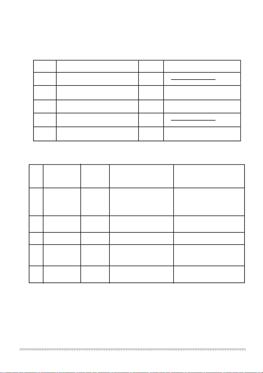
1. Please check the packing list of the centralized controller,whether the components are
complete.
No.
Centralized controller
1
Cross-recessed head tapping
2
screws
Fastening plastic expansion pipe
3
Installation & Operation Manual
4
Matching
5
2. Installation assemblies prepared on the site
No.
Name
3-core control
1
shielded cable
3-core cable
2
Switch box
3
Wire pipe(jack
4
casing pipe,
captive nut)
Tighten strip
5 ————
Name
resistance 120 Ω
Quantity
(install into
wall)
2 PCS
1 PCS
1 PCS
2/3 PCS
Several
pieces
Selected model
RVVP-300/300 3×0.75mm
RVV-300/500 3×1.5mm
Quantity
————
————
Remarks
1
6
6
1
4
GB845/ST3.9*25-C-H(S)
Φ6*30
Remarks
One for communicating with
the air conditioner; the other
2
for communicating with the
computer.
For power supply of the
2
centralized controller
————
————
For binding cables(as the
case maybe)
Installation & Owner‘s Manual
2
Page 6
1.2 Installation instructions
Installation instructions
1) Connect 220VAC power to the L、N terminals of the centralized controller directly.
2) Do not lay the signal wire and the power wire of the centralized controller in the same power
wire pipe, there should be 300~500mm distance between two pipes.
3) The signal wire of centralized controller should not exceed 1200m.
4) No intermediate joint is allowed for the shielded cable. If joints are inevitable, crimp it with the
terminal block.
5) After the centralized controller is connected, do not use megohmmeter to inspect the insulation
of the signal cable.
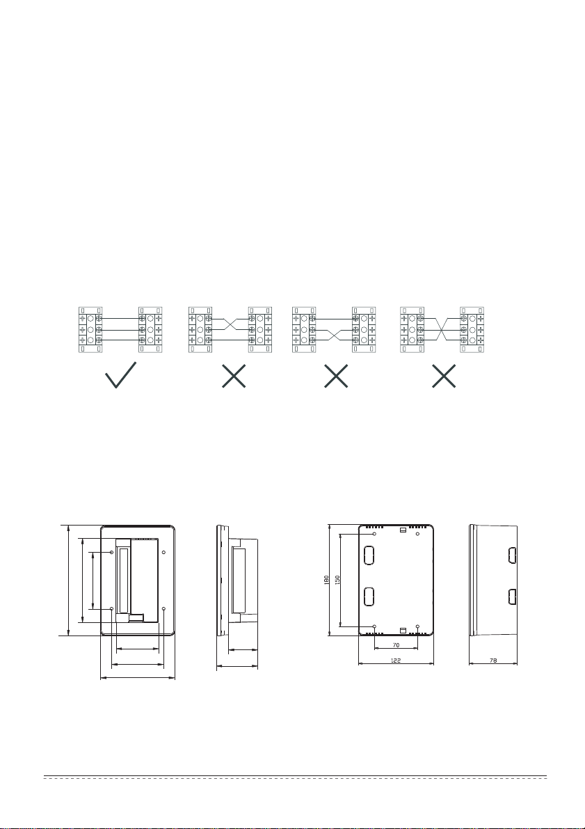
6) Wiring mode of the centralized controller and the network interface:
The communication port between the centralized controller and the network interface of the air
conditioner is polarity-sensitive.The X,Y and E at both sides should correspond properly. Dot
not cross-connect the signal wires,the same to the RS485-RS232 of the centralized controller.
Correct connection
X
X
Y
E
E Y
1.3
Installation methods
92
180
137
70
85
122
Incorrect connection
X
Y
E
48.5
68
CCM30/BKE-A
CE-CCM30/BKE-A
Incorrect connection
X
E Y
Incorrect connection
X
X
Y
E
E Y
X
X
Y
E
E Y
CCM30/BKE-B
CE-CCM30/BKE-B
Fig.1.1 Centralized controller size (unit: mm)
Installation & Owner‘s Manual
3
Page 7
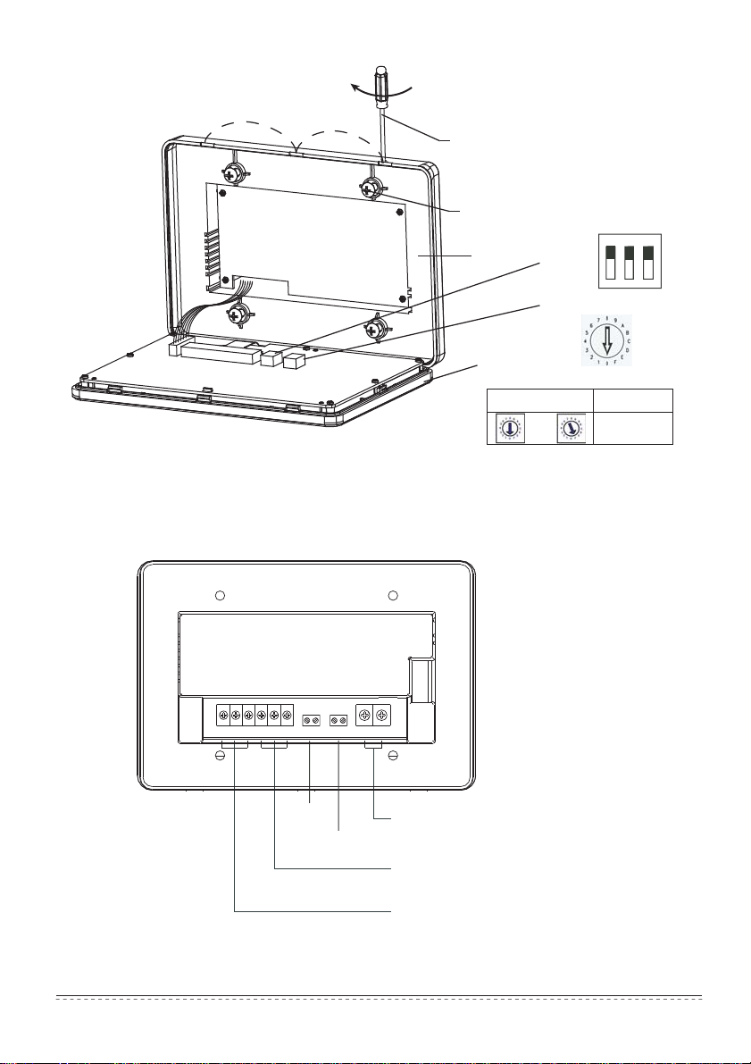
Insert the flathead screwdriver into the
concave on the upper side of the box,
and rotate slightly to open the upper cover(3 places).
Fix the screws of the centralized controller
(GB845/ST3.9*25)
1
2
3
Base
Front cover
Dial code
ON
Address dial code
Fig. 1.2 Installation diagram
X X Y E F1F1 F2F2 E E FORCED ON EMG.STOP L N N
Forced on
switch
Emergency
stop switch
L、N terminals
(198V~242V)/(50/60Hz)
Communication terminal with computer
Communication terminal with air conditioner
Fig.1.3 Terminal instruction of centralized controller
Dial code position
~
Address range
0 0 ~ 15
Installation & Owner‘s Manual
4
Page 8
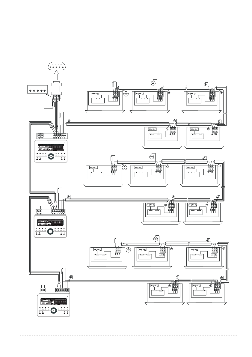
1.4 System wiring instruction
Network air conditioner wiring diagram (two types for indoor unit: one is the main control board
with an external network interface module; the other is the network interface module is built in the
main control board).
RS232 pin buckle: insert the COM port of computer
One computer can connect 16 centralized controllers at most
RS485-to-RS232
module
E
F E
F F
F
F F F
F
2 2 1 1
Matched resistance of
communication
terminal 120 Ω
Reliably ground the shielding terminal
Other centralized
controllers
POWER
Centralized
controller
POWER
Matched resistance of
communication
terminal 120 Ω
Matched resistance of
communication
terminal 120
Centralized
controller
Matched resistance of
communication
terminal 120
Ω
Ω
Electronic
Indoor unit Indoor unit Indoor unit
Matched resistance of
communication
terminal 120
Indoor unit Indoor unit Indoor unit
Matched resistance of
communication
terminal 120
Indoor unit Indoor unit Indoor unit
control box
A centralized controller can connect 64 indoor units at most
Ω
Electronic
control box
A centralized controller can connect 64 indoor units at most
Ω
Electronic
control box
A centralized controller can connect 64 indoor units at most
Electronic
control box
Electronic
Indoor unit Indoor unit
Reliably ground the shielding terminal
Indoor unit Indoor unit
control box
Electronic
control box
Electronic
control box
Reliably ground the shielding terminal
Electronic
control box
Electronic
control box
Electronic
control box
Electronic
control box
Electronic
control box
Electronic
control box
POWER
T N F1 F2 E X Y E
Centralized
controller
Fig.1.4 Wiring diagram
Electronic
Indoor unit Indoor unit
control box
Installation & Owner‘s Manual
Electronic
control box
5
Page 9
Note
The RS485-to-RS232 module and the wires in the wiring diagram are used when the network
system needs to connect with the computer only. One computer can connect with 16 centralized
controllers at most, Namely the maximum of indoor units is 16X64=1024 ,that a network system
can connect. The centralized controllers can be distinguished by address code,which setting range
is 0 to 15. No duplicate addresses is allowed in a same network.
1.5 Safety precautions
S afet y p r eca u ti o ns
! Read the safet y precautions carefull y before installing the unit.
! Stated belo w are important safet y issues that must be obe y ed.
! The meanings of all parts are as follo w s:
Warning
Note
! Upon completio n of the installati o n, check w heth e r the trial run is n ormal, and deliv er the
u s e r 's m anu al to the us er.
Means improper handling may lead to personal injury or property loss.
Means improper handling may lead to personal death or severe injury.
Warning
Please entrust the distributor or professionals to install the equipment. Installation by unauthorized
persons may lead to imperfect installation which may result in electric shock or fire.
Adhere to this installation manual. Improp e r installation m a y lea d to electric shock or fire.
Reinstallation m ust be perfor m e d b y professionals. Improper installation ma y
shock or fire.
Do not uninstall the e q on. Unauthoriz ed uninstalling
operation, h e
ating or fire o f th e
uipment w i t hout permiss i
air
conditioner.
ma y l ead t o
lead to electric
abn o rmal
Note
not install th e equipment in a place vulnerable to leakage of flammable gases. Once
Do
flam m able gases are leaked and left a r oun d the centralize d controller,fire may occur.
The w i ring shall adapt to the cur r ent of the centr a lized controller .
h e ating m a y occur and result i n fire.
Otherwise electric leakage or
Installation & Owner‘s Manual
6
Page 10

1.6 System wiring instruction.
1) Wiring diagram of
building net w ork air conditioning s y stem.
(a)
(b)
(a) The wiring system is good for communication,recommended
(b) The wiring system is bad for communication,not recommended
2) System wiring diagram of centralized controller and indoor unit of air conditioner.
Both
of the follo w ing w i ring mo d e s of centralized
(The number
of indoor unit s connected w i th each centralized controller is not beyond 64)
controller a nd indoor unit are
applicable:
Indoor unit
Indoor unit Indoor unit Indoor unit Indoor unit Indoor unit
Centralized controller
Indoor unit Indoor unit Indoor unit Indoor unit Indoor unit Indoor unit
Centralized controller
Fig.1.5 Wiring diagram of centralized controller and indoor unit of air conditioner
Installation & Owner‘s Manual
7
Page 11

OPERATION PART
Installation & Owner‘s Manual
8
Page 12

2.1 Function instructions
1. Centralized controller is used for controlling and data querying of air conditioners in the network.
Each centralized controller can be connected to maximum 64 indoor units, through 485
communication can to form an air conditioner LAN and realize the centralized controlling
network in the air conditioner.
2. Centralized controller can connect with computer or gateway, to realize the LAN connection
between computer and all the air conditioners , then can use computer to remote control
(the computer software must support it). Each local computer or gateway maximally connect
16 centralized controllers.
3. Between centralized controller and air conditioner, computer and centralized controller are
applied to the master-slave responding communication method. In the LAN of centralized
controller and air conditioner, centralized controller will be the master unit, and the air
conditioner will be the slave unit. In the LAN of computer and centralized controller, the
computer or gateway will be the master unit, and the centralized controller will be the slave unit.
Air conditioner
Network
interface
Network interface
may be gathered on
the indoor unit main
control board
Local computer
Centralized controller
……
Maximally 64
……
……
indoor units
Fig.2.1 Air conditioner network control system structure diagram
2.2 Operation conditions
1. Power and voltage range:
Input voltage: single phase 198V~242V;
AC input power frequency: 50Hz/60Hz;
2. Operating environment temperature: -15℃ ~+43℃;
3. Operating environment humidity: RH40%~RH90%.
……
Maximally 16
centralized controllers
……
Installation & Owner‘s Manual
Internet
9
Page 13

2.3
Key words
2.3.1 State indication
1. LED for state indication
1) Normal state
① On
The LED will be on when any one of the following occur:
a) In the centralized controller network, one or more air conditioners are under operating
state.
b) Through the centralized controller’s operation, when the centralized controller is sending
order to the air conditioners,the LED will be on. When centralized controller finishes
sending,the LED will be off.
② Off
The air conditioners in the centralized controller network are all under off status.
2) Abnormal state
If the air conditioners in the centralized controller network are error or the controller network
is error, the LED will flash as 2 Hz.
2. Backlight
The backlight will be on by pressing any key except” ”,when the backlight is off.
The backlight will be on,when centralized controller is operating,
The backlight will be off, if no key is pressed over 30s.
3. Buzzer
When the backlight is on and the centralized controller keys are un-lock, any key (except for
the ) is pressed ,the centralized controller will carry on relative function, the buzzer will buzz
once . If this key has long press function, the centralized controller will carry on the relative
functin, but the buzzer will buzz once only.
When the backlight is off, any key (except for key) is pressed, only the backlight is lighted
on, the centralized controller will not operate the key, and the buzzer will not buzz.
2.3.2 Power on or reset
the centralized controller is po w ered o n or reset through the key :
When
The buzzer long buzz for 2 seconds: all display segments of LCD are luminous for 2 seconds
and then goes off;
1 secon d later, th e s y ste m e nters the
is in the
conditioners
air
network.
O ce n the search is finished, the centralized
and sets t he first
2.3.3
Emergency stop and forced on
When the emergent stop switch of the centralized controller is connected,all the air conditioners
in the centralized controller network will be shut down compulsorily,and the LED flashes
as 0.5Hz.The centralized controller and computer and all functional modules are disabled from
startup and shutdown until the emergent stop switch is break. When the forced on switch
Installation & Owner‘s Manual
di s l a y d y s main page p status an displa the first page,
in
the
in-service air conditioner b y default.
nor m a l display status .
an searches the in-service
controller
enters the mode setting p a ge,
The centralized controller
d
10
Page 14

of the centralized controller is connected, all air conditioners in the nerwork of the centralized
controller will start up compulsorily. By default, they will run in the cooling mood. The startup
and shutdown operations of the centralized controller and computer and all functional
modules will be disabled (only the command of startup is sent to the air conditioner,without
affecting operation of the remote controller after startup) until the forced on switch is break.
If the foregoing two switches are connected concurrently,the emergent stop switch
shall have preference.
2.3.4 Various locking
1. Centralized controller locking
The centralized controller locking state will be recorded when powered off. It won’t dismiss
when re-power on until receiving the unlocking order.
1) Effect
① When the centralized controller is under locking state, it can not change the air
conditioner’s operating state through the centralized controller (such as ON/OFF the unit,
setting mode, change the setting temperature, change the fan speed, unlock the exiting
locking state etc), but it can do the query operation, until unlocking and then recover to
normal.
② When the centralized controller is under locking state, all the air conditioners in the
centralized controller network will be remote controller locked.
2) Operation
① Locking
The centralized controller can be locked by the computer only.
② Unlocking
a) When the centralized controller and computer communicate normally
The centralized controller can be unlocked by the computer only. When the
centralized controller is unlocked, the controller will send order to unlock the remote
controller locking of all the air conditioners.
b) When the centralized controller and computer communicate abnormally
When the centralized controller is locking, the centralized controller can be unlocked
by the way that press “ ”key and hold on, then press “ ” (It should operate within one
minute after centralized controller is re-powered on or the “ ” is pressed).
The remote controller locking of the air conditioner is remained.
2. Remote controller locking
1) Effect
① When the air conditioner is under remote controller locking state, it will not receive
the remote signals from remote controller or wire controller, until unlocking.
② The air conditioner can be operated by the centralized controller.
2) Operation
① Can lock or unlock through the computer.
② Can operate by centralized controller.
In the centralized controller setting interface, press “ ” to lock or unlock.
If the current state is remote controller locking, press the key to unlock.
If there’s no remote controller locking, press the key to lock.
3. Mode locking
1) Effect
Under mode locking state, through centralized controller to operate the air conditioner,
only can choose the mode which has not conflict with locking mode.
Installation & Owner‘s Manual
11
Page 15

2) Operation
Can set the heating mode locking or cooling mode locking.
Under mode locking state, if set the new mode locking, it must be unlocking first, then can
operate the new mode locking.
① Can lock or unlock through the computer.
② Can operate by centralized controller.
In the centralized controller setting interface, choose all the air conditioners of the
centralized controller network as the object, press “ ” and hold on, then press “ ” to
do the mode locking or unlocking.
If the current state is mode locking, press the key to unlock.
If there’s no mode locking, press the key to lock.
4. Centralized controller key locking and unlocking
1) Effect
When centralized controller keys are locked, keys operation is invalid except “ ” key and
unlock keys.
2) Operation
1. Press “ ” key and hold on, then press “ ” key, the keys of centralized controller will
be locked or unlocked.
If the current state is key locking, press the key to unlock.
If no centralized controller key locking, press the key to lock.
2.When the backlight turns off, the keys will be locked automatically. Press any key to light
the backlight first. Secondly, press “ ” key and hold on, press “ ” key to unlock keys. Then
operation to the controller is enabled.
The backlight will turn off and the keys will be locked automatically if there’s no operation
within 30 seconds.
2.3.5 ON and OFF operation
Use the “ ” key or “ ”key to do the ON and OFF operation for the air
conditioners in the centralized controller network.
The ON mode will accord to the system mode locking or other limit conditions
for judging, if there is conflict, it will auto adjust to the next mode without conflict; if
all the modes have conflict, then it can not operate the unit.
1. Use “ ” key to ON and OFF the unit
Can operate a single air conditioner or all the air conditioners in the centralized controller
network.
1) Choose the object. Press“ ” key to choose a single air conditioner or all the air
conditioners in the centralized controller network. If choose a single air conditioner,
then use “ ”, “ ”, “ ”, and “ ” to choose the air conditioner.
2) Use“ ”, “ ”, “ ”, and “ ” to set the operating mode and operating parameters,
such as fan speed, setting temperature etc.
3) Use “ ” key, centralized controller send the relative order to the operating object.
After setting the operating parameter for the air conditioner, if not press the “ ” key the
setting parameter will not be sent to the air conditioner, and the current operation of the air
conditioner is not affected (except locking operation).
2. Use “ ” key to ON and OFF the unit
Only can operate all the air conditioners in the centralized controller network, not for
single air conditioner.
“ ” key long press: press this key for over 2 seconds then loose.
“ ” key short press: press this key and then loose within 2 seconds.
According to different states and operation ways of air conditions in the current
centralized, there are following situations:
Installation & Owner‘s Manual
12
Page 16

1) One or more air conditioners under ON state (include timing process of timing ON
and OFF)
“ ” key only has short press function.
Only send the OFF order to the air conditioners with ON state, not for OFF state units.
The memory function is activated, the current state of all air conditioners is memo-
rized.
2) All the air conditioners in the centralized controller network are OFF states
① “ ” key short press
The centralized controller reads the memory contents, and sends relative order to all
air conditioners.
② “ ” key long press
a) If current page is setting parameters, and the setting mode is not OFF, the central-
ized controller will send orders to all air conditioners according to parameters, such as setting
mode, fan speed, setting temperature, etc.
b) If the current is under setting interface but the setting mode is OFF state or under
other interfaces, the centralized controller will send the default ON order to all air
conditioners. The default ON order is : cooling mode, high fan speed, setting temperature
is 24℃ or76℉, operate the swinging function.
Installation & Owner‘s Manual
13
Page 17

2.4 Instruction of electric control function
Keys of centralized controller
In the setting pageswing function
is enabled or disabled
1、In the setting page, set the
temperature,increase or decrease
the time of timing on/off.
2、In the query page ,scroll page of
the parameters being queried.
In the setting page, set the operation
mode of the air conditioner.
SWING INC
In the setting page, shift to the timing startup/shutdown
setting page to set the air speed of the air conditioner.
FAN
MODE
LOCK DEC
1. In the setting page, press the “lock” key to lock or unlock the
remote controller.
2. In the unified setting page, press the “Up” key and hold on
then press the “Lock” key to lock or unlock the mode.
3. After pressing the “Query” key and hold on, press the “Lock”
key to lock or unlock the keypad of the centralized controller.
Enter the air conditioner seting page to shift
In the setting page, press the “OK” key to send the setting
information except the locking signal to the air conditioner.
Installation & Owner‘s Manual
14
1. “Up” and “Down” keys: For
selecting rows.
2. “Left’ and ”Right” keys: For
Enter the air conditioner query pages.
between singlemachine seting and global seting.
selecting columns.
OK TIME ON SET QUERY
RESET TIME OFF
press the “Reset”key
On/Off the unit
In the setting page,
shift to the timing
startup/shutdown
setting page.
centralized
five seconds to reset
the
controller
Fig.2.2 Keys of centralized
Page 18

2.4.1 Key operaion instruction
1. Query key “ ”
Any time when you press the key, the selected operation mode is to query the operation
status of the air conditioner.
By default, the first in-service air conditioner will be queried.
2. Set key “ ”
In other display mode,press the key “ ” to enter the setting mode.
By default, it is single setting, and the first in-service air conditioner is displayed.
In setting operation mode, press the key “ ” again, and the operation will be
performed for all air conditioners in the network. Press the key repeatedly to shift between
single setting and global setting.
→ Singl e → Globa l →
3. Mode key “ ”
In setting operation mode,Press this key to set the operation.
→coolin
g → heating →
Fan only
→ off
→
4. Fan key “ ”
In setting operation mode, press this key to set the fan of the indoor unit of the air
conditioner to run in the automatic, high, medium or low level of air.
auto → lo w → mediu m → high →
→
5. Time on key “ ”
In setting operation mode, press this key “ ” to set the timing startup of air
conditioner;
Press the key “ ” again to exit the timing setting, and restore the normal
temperature regulation operation mode.
6. Time off key “ ”
In setting operation mode, press this key “ ” to set the timing shutdown of air
conditioner,
Press the key “ ” again to exit the timing setting, and restore the normal
temperature regulation operation mode.
7. Swing key “ ”
In setting operation mode, press this key “ ” to enable or disable the swing function.
If all currently selected air conditioners have no swing function, no effect will result after
pressing the key.
8. Leftward key “ ”
In the query mode, if this key is pressed, the operation status data of the previous
air conditioner will be displayed. If it is currently on the first machine, the data of the last
machine will be displayed,when the key is pressed . If you hold down this key, the address
will decrease one by one.
In the setting mode, if it is in single operation mode, the air conditioner of the previous
in-service address number will be selected,when this key is pressed, If it is in the global
operation mode, no effect will result when this key is pressed.
In the main page , press the key to enter the query mode. By default, it is the first
in-service air conditioner.
Installation & Owner‘s Manual
15
Page 19

9. Rightward key “ ”
In the query mode, when the key is pressed, the next in-service air conditioner is
selected,and its operation status data will be displayed.If it is currently on the last air
conditioner, the first one is selected and its data displays, when the key is pressed. If this key
is hold down long, the address will increase one by one.
In the setting mode, if it is in the single operation mode, when the key is pressed, the
next in-service air conditioner will be selected. If it is in the global operation mode, no effect
will result when the key is pressed.
In the main page, press the key to enter the query mode. By default, it is the first
in-service air conditioner.
10. Downward key “ ”
In the main page, press this key “ ” to enter the query mode. By default, it is the
first in-service air conditioner.
In any other time, press this key “ ” will select the next row corresponding
position air conditioner.
In the setting mode, if the global operation mode is selected, this key “ ” is invalid.
If it is on the last row, press this key “ ” again to shift to the first row air conditioner.
If this key “ ” is hold down long, the row will increase one by one.
11. Upward key “ ”
In the main page, press this key “ ” to enter the query mode. By default, it is the
first in-service air conditioner.
In any other time, press this key “ ” will select the previous corresponding position
air conditioner.
In the setting mode, if selected all the air conditioners to operate, this key “ ” is
invalid.
If it is on the first row, press this key “ ” again, and shift to the last row
corresponding air conditioner.
If you hold down this key “ ”, the row will decrease one by one.
12. Add key “ ”
1) Query mode
Press this key “ ”, display the data of the last page.
If it is now in the last page, press the key “ ” again and the first page will be
displayed.
2) Setting operation mode
① Temperature adjusting method
Press this key “ ”, the setting temperature will increase one degree.
If you hold down the key “ ”, the setting temperature will increase one by one.
When reached the highest allowed set temperature, it can not increase.
② Timing on or timing off setting method
Press this key “ ”, it will select the next setting time.
If you hold down the key “ ”, the next data will be selected one by one.
When reached the max. allowed setting time, it can not increase.
The timing seting change mode is as follow:
0 . 5 2 . 0 1 . 5 1 . 0
0 . 0
10 9 . 0 8 . 5 8 . 0 7 . 5 7 . 0 6 . 5 6 . 0
19 21 22 23 24
Installation & Owner‘s Manual
13 12 11 9 . 5
14
15 16 17 18 20
16
5 . 5 5 . 0 4 . 5 4 . 0 3 . 5 3 . 0 2 . 5
Page 20

13. Reduce key “ ”
1) Query mode
Press this “ ” key, display the data of the previous page.
If it is now in the first page, press the key “ ” again and the last page will be
displayed.
2) Setting operation mode
① Temperature adjusting method
Press this key “ ”, the setting temperature will decrease one degree.
If you hold down the key “ ”, the setting temperature will decrease one by one.
When reached the lowest allowed set temperature, it can not decrease.
② Timing on or timing off setting method
Press this key “ ”, it will select the next setting time.
If you hold down the key “ ”, the next data will be selected one by one.
When reached the min allowed setting time, it can not decrease.
The timing seting change mode is as follow:
24
23 20 21 22
13 14 15 16 17 18 19
5 . 5 6 . 0 6 . 5 7 . 5
5 . 0
4 . 5 4 . 0 3 . 5 3 . 0 2 . 0
14. ON/OFF key “ ”
Any time when you press the key “ ”, the centralized startup/shutdown operation is
performed for all current in-service air conditioners in the centralized controller network.
Detailed operation refers to P12.
15. Confirmation key “ ”
In the setting mode, press the key “ ” to send the currently selected mode status
and the auxiliary function status to the selected air conditioner.
Detailed operation refers to P12.
16. Reset key “ ”
Any time when the reset key “ ” is pressed, the centralized controller will reset. The
result is the same as the result of restoring power-on after power failure.
17. Lock key “ ”
Any time when this key “ ” is pressed, the selected air conditioner can be locked or
unlocked.
Detailed operation refers to P11.
7 . 0 8 . 0 8 . 5 9 . 0 9 . 5 10 11 12
2 . 5 1 . 5 1 . 0 0 . 5 0 . 0
Installation & Owner‘s Manual
17
Page 21

D C L f o y a l p s i d l l u F
5 1 - 0 0
h
c a e d n a s d i r g *16 4 f o d e s
s
,
n
o i t
a r
e p
o
y
a l
p
s i D
y r a i l i x u a c i r t c e l E
n o i t c n u f g n i w S
u t a t s n o i t a c i
. n o i t a r e p o , g n i p u o r g
g
n i t t
e s
, y r
e
u Q : s u t a t s
n
u m
m
o
C
n o i t c n u f g n i t a e h
n o i t a l i t n e V
(1.6)
e d
o
m
g
n i t
t
e s
o
p m o c s i x i r t a m e h T . 1
r e l l
o
g n i k c o l y e K
r t n o c
g n i k c o l
e
t
o m e R
e h T . t i n
. s e z i s t n e r e f f i d f o s k o o l b o w t f o d e s o p m o c s i d i r g
l a c i t r e v e h t d n a e t a n i d r o o c l a t n o z i r o h e h t f o m u s
. d i r g e h
,
+
8 4
s e t a n
d
n a + 2 3 , + 6 1 , + 0 0 s e t a n i d r o
i
d r o
o
c
l a t n
o
z
i r
o
h e d u
l c
n i
o
c l a c i t r e v d n a
x
i
r
t a m
e
h
T
.
2
e d o m g n i t a e H
g n i k c o l
s
i
h
t
f o
u r o
t i n u
t
f o
o
d n i e h t f o s s e r d d a e h t e t a c i d n i h c i h w
s
r o
s e r
o
d
d
n
d a
i n a o t
e
h t s i d i r g e
s d
n
o
p s
h t
e r
r o c d i r g
f
o e t a n i d
. s s e r d d a
h c a
r
o
o
E
c
e d
o
g n i k c o l
m g n i
l o
o
C
n o i t c n
e
l
n o
u d o m e
i
t
a c i
u
f g n i t t e w e D
n u
n
o h p
m m o c
e
l e T
e
n
l
e l u e d o
m
S M S
Installation & Owner‘s Manual
n o i t a c i n
o
u d
i
t a c
o
i
m n
n u m
u
o
i t
m m o c
c
m o m
n u F
18
F F
e r u t a r
r e t e m a r a p
O
/ N O g n
e
p m e T
e d o c n
d n a t l u a F
o
i
t
c e t
o
r p
i
m i T
r u o H
,heating g n i l o o c
k
r a m
:
n
o i t c e l e s
, o t u A
e
d o M
Fig.2.3
Fan speed
e r u t a r e p m e t r o o d n I
n o
i
r e t u p m o C
t
a c i
n
u m m o c
Page 22

2.4.2 LCD instruction
1. General display data
1) General display data is displayed in all display pages.
①The icon displayes when the centralized controller communicates with the
computer or gateway normally, otherwise, it does’t display.
②The icon displayes when the centralized controller communicates with the
functional module normally,otherwise, it does’t display.
③The icon displayes when the centralized controller communicates with the
the SMS remote control module normally, otherwise, it does’t display.
④The icon displayes when the centralized controller communicates with the
the telephone remote control normally, otherwise, it does’t display.
⑤The icon displayes in the cycle: (blank)→ → → →(blank),when the
centralized controller communicates with the network interface normally.
⑥The icon “ ” displays as 0.5Hz when the current state is centralized controller
locking. The icon will be displayed constantly when the state is key locking.
⑦The icon “ ”displays when the current state of the selected air conditioner
is remote control locking.
The icon will always display if all the air conditioners are remote control locking.
In the global setting page,the icon displays if any air conditioner is remote
control locking.
⑧The icon “ ” will be displayed, if the current state is cooling mode locking.
The icon“ ” will be displayed, if the current state is heating mode locking.
2) Display data instruction
①Indoor unit code (address) display: Display range:00~63;with “#” being
luminous concurrently.
②Indoor temperature display: Display range:00~99°C (or 99°F). “°C” (or “°F”)
and “indoor temperature” are displayed concurrently. If the temperature is higher
than 99°C(or 99°F), 99°C(or 99°F) is displayed. If the temperature value is invalid,
“- -” is displayed.
③If timing startup/shutdown is set, the flag is displayed.
④T3, T2A and T2B display: In the single-machine query page, display can shift
among “T3”, “T2A” and “T2B”, and the temperature value is displayed concurrently,
with the corresponding “°C” (or “°F”) being luminous.
⑤In case of air conditioner fault or protection, the corresponding fault code or
can be displayed.
⑥Liquid crystal matrix display description:
Installation & Owner‘s Manual
19
Page 23

a. The array of the liquid crystal display is composed of 4X16 grids, and each grid is
composed of two blocks of different sizes (as shown in the above figure). The
status indication table is as follows:
Status
Object
Big black
block
Small black
block
b. The array includes horizontal coordinates 00-15 on the up side and vertical
coordinates 00+, 16+, 32+ and 48+ on the left side, which indicate the address of
the indoor unit. The sum the horizontal coordinate and the vertical coordinate
composes the grid the address of the grid. Each grid corresponds to an indoor unit
of this address.
2. LCD display description
1) Description of the main page
Fig 2.5 The example diagram of the main page
Constantly on Slow blink Fast blink Not bright
Out of
service
Power
off
In-service
Power on
Selected
Fault of
indoor/
outdoor
unit
①The LCD displays the main page, 60 air conditioners are in service, which 28 are
powered on and 32 off.
②The address of the air conditioners is sum of the coordinates. For example, the
address of (48+,09) is 48+09=57.
③In the array, the big dots from (16+,00) to (32+,15) are luminous, and the small dots
are not luminous. It indicates the 32 air conditioners with the addresses from 16 to 47 are
powered off.
④In the array, the big and small dots from (48+,09) to (48+,12) are not luminous. It
indicates the four air conditioners with the addresses from 57 to 60 are outside.
⑤All other big and small dots in the array are luminous. It indicates all other air
conditioners are in the net powered on.
⑥The centralized controller communicates with the computer normally,when the
keypad of the centralized controller is locked.
Installation & Owner‘s Manual
20
Page 24

2)
Description of the query page
Fig 2.6 The example diagram of the query page
①The LCD display shows the query page, and the air conditioner with the address of
01 is being queried.
②Mode of the air conditioner with the address 01 is: Cooling, strong air, swing on,
indoor temperature 22°C,set temperature 20°C, cooling mode “lock”.
③In the array, only the big and small black dots at (00+,00) and (00+,01) are luminous .
It indicates the in-service and power-on status of the air conditioners with the addresses of
00 and 01.
④The centralized controller communicates with the computer normally.
3) Description of the setting page
Fig 2.7 The example diagram of setting page
①The LCD display shows the setting page, and queries the air conditioner with the
address of 01 .
②THe mode of the air conditioner with the address 01 is: Cooling, strong air, swing on,
set temperature 22°C, cooling.
③In the array,only the big black dots at (00+,01) to (00+,15) are luminous. It indicates
the air conditioners with the addresses 01 and 15 are in service.
④The centralized controller communicates with the computer normally.
Installation & Owner‘s Manual
21
Page 25

Fault page display description
4)
Fig 2.8 The example diagram of fault page
①Query the air conditioner with the address of 08 in the query page.
②The air conditioner with the address of 08 is faulty, and fault code is 08. The big black
dot below (00+,08) blinks.
③In the array,only the big and small black dots at (00+,00) and (16+,15) illuminate.
It indicates the in-service status of the air conditioner power on, with the addresses 00
and 31.
④The centralized controller communicates with the computer normally.
2.4.3 Other specifications
1. Dial code operation specification
ON
2
1
Dial code 1
Dial code 2
Dial code 3
3
Table 2-1 Dial code definitions
ON OFF
Dial code 1
Dial code 2
Dial code 3
Three-pipe CCM30 Two-pipe CCM30
Fahrenheit
Has optional function No optional function
Centigrade
2. reminding function to clear the filter
① When the time of centralized controller powered on add up to the selected
parameter time, the centralized controller will remind the user to clear the filter.
The reminding dual eight (Fig. 2.9c) displays “FL”.
② When the centralized controller display FL, it needs to manual operation to clear
this reminding. Press “ ” key and hold on then press “ ” key, can clear FL reminding.
At the same time,the accumulated time of centralized controller powered on will be cleared.
Installation & Owner‘s Manual
22
Page 26

00 01 02 03 04 05 06 07 08 09 10 11 12 13 14 15
00+
16+
32+
48+
a. Function selection b. Parameter selection c. Reminding d. “Set successfully” reminding
Fig 2.9 Filter net in addition to the dust function involves of show a contents
2) Function setting
① Dial the dial code 3 to “ON”, select the “Has optional function”referring to table 2.1 to , and
then power on the centralized controller, in 1 minute press “ ” key and hold on then press “ ”
key, enter to optional function setting. Dual eight represented function selection (Fig.2.9 a) will be
flashed with 1Hz frequency (default display 00), display the optional function code (see table 2.2).
Press “ ” and “ ” keys to select function, and then press “ ” key to enter parameter
selection.
②After enter parameter selection, dual eight represented function selection will be lighted
on, dual eight represented parameter selection (Fig.2.9 b) will be flashed with 1Hz frequency,
display optional parameter code. Through pressing “ ” and “ ” keys to select the detailed
parameter.
③Press “ ” to confirm parameter selection(details parameter codes’ corresponding time
refer to table 2.3).
④After setting successfully, Dual eight represented function selection and dual eight
represented function selection will be lighted on, the screen will display “Setting successfully”
(Fig. 2.9 d). After 3 seconds will auto exit optional function setting. The screen will back to normal
display.
After enter optional function setting, no operations in 5 seconds will auto exit function
selection, the setting parameter will not change. Only press “ ” key to confirm the parameter
then the setting parameter will save.
Table 2-3 The code of different times
Table 2-2 The code of selecting the clear filter
function
Function
code
00
01
Function setting
Only display, no function
Cleaning filter screen
reminding
of reminding clear filter
Parameter code
Time (hour)
00
01
02
03
04
0
1250
2500
5000
10000
Installation & Owner‘s Manual
23
Page 27

2.4.4 Fault and protection code table
Fault code
EF
EE
ED
EC
EB
EA
E9
E8
E7
E6
E5
E4
E3
E2
E1
E0
07#
06#
05#
04#
03#
02#
01#
00#
Fault content Description
Other faults
Water level detection faults
Reserved
Cleaning fault
Inverter module protection
Over-current of compressor(4 times)
Fault of communication between main board and display board
Air speed detection out of control
EEPROM error
Zero crossing detection error
Outdoor unit fault protection
T2B sensor fault
T2A sensor fault
T1 sensor fault
Communication fault
Phase order error or phase loss
Fault of communication between centralized controller and computer (gateway)
Fault of communication between centralized controller and functional module
Fault of communication between centralized controller and network interface module
Fault of communication between network interface module and main control board
Protection
code
Other protection
PF
Reserved
PE
Reserved
PD
Reserved
PC
Reserved
PB
Reserved
PA
Reserved
P9
Over-current of compressor
P8
Power supply over-voltage and undervoltage protection
P7
Discharge low pressure protection
P6
Discharge high pressure protection
P5
Discharge pipe temperature protection
P4
Compressor temperature protection
P3
Condenser high-temperature protection
P2
Anti cool air or defrost protection
P1
Evaporator temperature protection
P0
Installation & Owner‘s Manual
24
Protection content
Description
Page 28

2.5 Technical indices and requirements
1. EMC, EMI comply with the CE certification requirements.
2. Electrical safety comply with GB4706.32-2004, GB/T7725-2004.
Installation & Owner‘s Manual
25
Page 29

MD12IU-028BW
202055100922
Page 30

更改内容,此页不做菲林
1、18页:修改图标
2、封底页:图号升级
 Loading...