

Page 1

Shunde Midea Dishwasher Manufacturing Co., Ltd.
Dishwasher Service Manual
Midea
Life can be lovelier.
Fully Automatic Double Pump
Page 2

For the sake of safe and efficient manipulation, you should prepare and learn to
use the following tools prior to servicing the dishwater: plus screwdriver, minus
screwdriver, H screwdriver, torque spanner, OTK caliper and universal meter.
Attention: never measure the resistance of live cord. Otherwise, you measuring
device may be damaged.
1. Dishwater does not work when
turned ON (No power indication).
Phenomena
Power socket defect.
Power cord defect.
Broken timer cord.
Lock malfunction.
Power switch failure.
Check socket.
See power cord.
See timer.
See door lock assembly.
See option switch and power switch.
Possible Causes
Service Instructions
Inlet valve core will not close.
Timer failure.
3. Overflowing incoming water.
Commonly Used Tools
Trouble Shooting
1
See protection and working
pressure switches.
See inner connecting wires.
Twisted inlet hose.
Excessive lower water pressure or
blocked water tap.
Inlet valve malfunction or blocked valve
filter.
Working pressure switch failure.
2. Small or no incoming
water.
4. Drainage activates again and
again without washing.
Working and protection
pressure switches failure.
See protection and working
pressure switches.
See inlet valve.
See timer.
Straighten up the inlet hose.
Check the water tap.
Check the inlet valve.
See protection and working
pressure switches and check
appropriate connecting wires.
5. Timer does not work.
6. Incomplete drainage.
7. Leakage.
Timer cord failure.
Timer failure.
Heating element failure (for heated
washing).
Thermostat failure.
Insufficient water.
See connecting wires.
See timer.
See heating element.
See thermostat.
See 2.
Twisted or blocked drain hose.
Pump motor failure.
Check drain hose.
See water pump motor assembly.
Tilted dishwater.
Unlocked door.
Broken connecting hose in
dishwasher.
Aged gasket.
Loose or defect inlet valve
connector.
Damaged pump.
Pump gasket failure.
Adjust the machine foot.
Lock the door.
Replace connecting hose.
Replace gasket.
Tighten the inlet valve. See inlet valve.
Reconnect the pump and the sump,
add gasket at the connector and
tighten the wedge.
See water pump motor assembly.
8. Dishwater powder retained in
the powder trough.
9. No brightness liquid from
dispenser.
10. Bad dispenser sealing
Caked dishwater powder.
Dishes block the water flow to the
dishwasher powder.
No brightness liquid in dispenser.
Electromagnetic valve does not
work.
See dishwater powder and
brightness liquid.
See loading of dishes.
See dispenser and inner
connecting wires.
Sealing cap failure.
Broken dispenser case.
Replace dispenser.
Protection or working pressure
switch failure.
Incorrect cord connection.
Page 3

Many of the performance failures of the dishwasher are not the result of mechanical troubles. And the
unsatisfactory washing result can usually be corrected without any service.
This manual deals first with the problems in performance. To have satisfactory washing result, you have to use the
machine correctly. First thing first, the dishes shall be placed in a correct manner. If the machine works well and
the washing result is unsatisfactory, you should check the layout of the dishes as follows:
Load the dishes as instructed in the user's manual.
Preparation of the dishes such as dumping the remaining food, and removing from the dishes food lumps,
starches in particular, shall be done prior to loading.
The dishes shall face the water flow from the spray arm for free washing. Do not place the dishes in an
overlapped way.
Load heavy pans and large soup bowls downwards. If the upper racks are barred from water flows, do not
place articles on them any more.
Leave some space in the front of the wire basket so that the water flow may wash out the dishwater powder
from the powder trough in the inner door.
On the fork/knife rack, the tableware shall be placed with handle down evenly. Do not load there the
articles that may fall out from the bottom.
2
11. Unsatisfactory washing
result.
13. Water drops at the door.
12. Unsatisfactory drying.
14. Difficult opening/shutting
of the door.
15. Excessive working noise.
16. Water accumulated in
bottom pan.
Bad sealing of hose connectors.
Salt spoon, colophony spoon or
water tank leakage.
Incomplete sealing of inner
container from sump.
Incomplete sealing of thermostat.
Collision of dishes.
Vibrating pump motor assembly.
Foreign articles in the pump.
Loose screws.
Improper loading of dishes.
Aged, incorrect or insufficient dishwater
powder.
Improper procedure selection.
Twisted or blocked drain hose.
Foreign articles in the main washing
system.
Blocked spray arm.
Brightness liquid leaks into the inner
container during washing.
Filter screen not clipped to the right
position.
Improper loading of dishes.
Brightness liquid not used.
Heating element problem.
Heated wash mode not selected.
Condensed vapor from air
vent.
Dislocated door gasket.
Bent lock linkage.
Disalignment of lock hook.
See loading of dishes.
Add brightness liquid.
See heating element.
Reselect procedure.
Normal phenomena.
Press gasket back to position.
See door lock assembly.
See door lock assembly.
See loading of dishes.
See motor and pump assembly.
Check screws.
Check water hoses.
Check water softener (WP5F).
Check the contact.
Check the contact.
See loading of dishes.
See dishwasher powder and brightness
liquid.
Reselect procedure.
Check drain hose.
Clean spray arm.
Replace dispenser.
Clip filter screen to the right position.
Note: in the narration of this manual, the number in brackets behind the part stands for the serial
number of the part in the explosion diagram. The double pump model in the explosion
diagram is equipped with a WP5E. The actual configuration may be different.
III. Check of Performance: Loading of Dishes
IV. Check of Performance: Dishwasher Powder and Brightness Liquid
The water (pressure, hardness and temperature) and the dishwasher powder are the major elements that affect the
washing effect of the machine. Choose the right dishwasher powder and dosage according to the local water
condition, you will have satisfactory washing result.
Use only the fresh and dry dishwasher powder of the designated brand. Outdated powder will reduce the
washing effect.
Contact the local water supply company for the water condition, if applicable. The higher the water hardness is,
the more powder shall be used.
Check the brightness liquid in the dispenser and add without delay if it is insufficient. The brightness liquid
helps the water to drip, making the dishes easy to dry and curbing the formation of water specks on the surface
of the dishes.
Page 4
¡¾Í¼1¡¿
A
B
¡¾Í¼2¡¿ ¡¾Í¼3¡¿
C
C
D
3
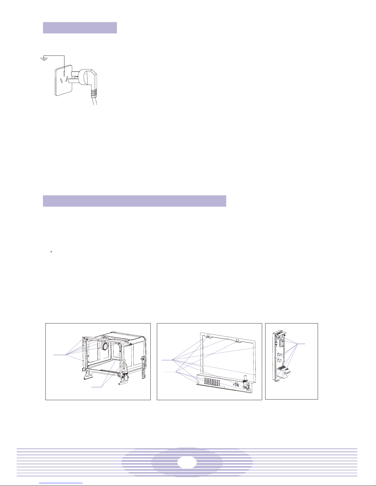
V. Power cord
The power cord of the dishwasher usually has a three-pin plug. Connect
the power supply as instructed in the user's manual.
If the dishwasher does not work, the power cord might be in the fault.
Most of the power cord troubles arise from damaged cord or loose
connection, and are visible.
Attention: to avoid electric shock, the power socket and power cord shall
be well grounded. Never use two-hole conversion connector that has no
ground terminals.
Steps for the check:
A. Disconnect the power prior to check.
b. Check the power plug. Improper connection may lead to bad contact.
c. Pull out the power plug in one stroke. Never pull at the power cord or use
a knife or other sharp tools that may cut the cord.
d. Check the power plug for overheat caused damage, corrosion or
looseness. In case of troubles, remove the outer casing (1) first, then the
rear panel (97) and replace the power cord (see Process 6).
e. Open the power cord clamp (96), remove the old power cord and replace
a new one with terminals. Secure the power terminals to the connection
terminals, and replace the power cord clamp.
f. Replace the rear panel and the outer casing.
VI. Removal of Outer Casing, Control Panel, Rear
This dishwasher is completely sealed. In order to repair internal parts, you have to remove the
outer casing before you can check and repair the parts.
Steps for the check:
a. Remove the three screws on the sides of the outer casing.
b. Open the door, and remove the six screws in the front of the inner container (see fig. 1 below). Note: do
not mix these stainless steel screws with the other ordinary ones.
c. Remove the seven screws in the back of the outer casing (see fig. 2 below).
d. Remove the screws in position D in fig. 2 below and take away the rear panel.
e. Lift up and away the outer casing from the dishwasher, and check and repair the internal parts.
f. Remove the six screws from the control panel bracing bar (58) (see fig. 3 below) and the two stainless
steel screws in position C of the inner container (see fig. 1 below), and pull out the control panel.
g. Remove the timer knob (see 1 in the appending diagram).
h. Turn the dishwasher upside down, remove all the screws in the bottom pan, open the cord clamp and
remove the bottom pan.
Page 5
Turn all the switches to OFF and pull out the power cord plug.
An ohmmeter and the ability to read circuit diagrams are needed in this step.
Remove the outer casing.
Pull out the two input terminals of the timer motor and measure them with an ohmmeter (use the
range of R 100). If the pointer does not sweep partly across the line, replace the timer.
Refer to the circuit diagram to check the connection of the timer terminal to the elements.
4
VII. Check Internal Connecting Wire
The internal connecting wire connects the timer (60), the power switch (61), the inlet valve (95), the heating
elements (45) and other electric elements together. The wires shall be kept intact. Any damage to the wire
may cause overheat and result in broken wire. Common troubles to the internal connecting wire are broken
wire, bad connection terminal contact, and connection terminal insulation layer damages.
To repair the dishwasher, the ground shall be connected. When an electric component is replaced, check
whether the ground is connected again. This is a crucial step to avoid electric shock and short circuit.
Attention: to replace electric cord, use the cord of the same temperature resistance and specifications. The
specifications and temperature rise are marked on the cord.
Turn all the control knobs to OFF and pull out the power cord plug.
Open the outer casing, and, if necessary, remove the bottom pan.
Check the wires and connectors and replace the damaged ones.
Steps for the check:
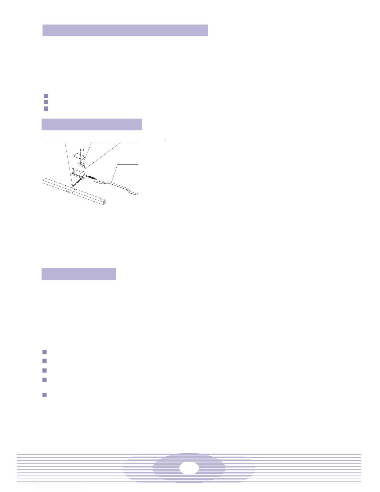
VIII. Door Lock Assembly
Slider
micro switch
Micro switch spring
Linkage
The working mechanism of the door lock is that the linkage (8)
bolts up the door hook, which, in its turn, presses the micro switch
spring in the lock assembly to form a closed circuit. The lock
mechanism consists of the door lock holder (11), the slider (10)
and the micro switch (3). When the door is opened, the door hook
is withdrawn to release the micro switch, cutting the power supply
for open door protection.
In case of worn out slider, micro switch failure or deformed micro
switch spring, troubles may occur and the dishwasher will stop to
work as usual.
Steps for the check:
a. Pull out the power cord plug prior to servicing the door lock
mechanism.
b. Remove the outer casing.
c. If micro switch failure is the case, disconnect the micro switch,
remove the two screws and replace a new micro switch.
d. In case of deformed micro switch spring, adjust the spring
with nipper pliers so that the micro switch returns to its
original position when the slider is released and the micro
switch closes when the slider is pressed tight.
IX. Timer
The timer of the dishwasher consists of a synchronous motor and various switches, and controls the
various operations of the dishwasher automatically. The step motor, like a clock, runs at constant speed.
When it passes through the selected procedure, the internal switches will open or close at a precise
sequence, realizing the control of the circuit over the internal components.
The output cords of the timer are in different colors. With a copy of the circuit diagram in hand, you can
track the circuit from the timer to any element.
The timer is a very reliable unit. In case of dishwasher troubles, check other causes first before focusing
on and replacing the timer.
Steps for the check:
Page 6

The option switch and power switch are push-button switches. Abrasion and use after an extensive period
may cause switch failure. When the switch is pressed, the power or high temperature pilot will not light up.
Check the power switch or the option switch.
Steps for the check:
Turn all the switches to OFF and pull out the power cord plug.
Remove the outer casing.
Press the power or option switch and check with an ohmmeter whether the normally open terminal
is closed. If it is not closed, replace the switch.
Remove the control panel, unscrew the screws to remove the defect switch, and replace with a new
one.
Connect the wires behind the switch and check if they are connected fast.
Replace the control panel and the outer casing.
The pressurecontrol of the dishwasher is realized through a float pressure switch composed of two micro
switches. The larger contact current (10A) controls the working level and the smaller current (3A) controls
the protection level. The working level is set at 78 85mm above the sump bottom, and the protection level
is 3mm or more below the brink of the inner container.
The check and adjustment of the pressure switch:
If pressure switch trouble is suspected, check whether the dishwasher is set level. If it is in level
position, remove the outer casing.
Add water to the inner container, and check whether the float and lever is choked. In case of
choking, correct it.
If the working pressure switch remains placid when the pressurein the water tank rises over 94mm,
the switch might be obstructed by the lever or damaged. In case of damaged switch, replace it.
X. Option Switch and Power Switch
5
XI. Inlet Valve
The inlet valve controls the water volume into the dishwasher. The electromagnetic valve is fixed on the
valve base. When it is powered, a magnetic field will come and pull the valve core to let in the water.
The feeding of the water depends on the timer, which controls the opening of the electromagnetic valve.
In normal circumstance, the pressurein the inner container of the dishwasher shall be 78 85mm above the
sump bottom. Open the door to check the pressurewhen water is filled.
During the washing operation, the inlet valve may open to add some water.
Steps for the check:
Check and replace the inlet valve.
a. Turn the power of the dishwasher to OFF, and pull out the power cord plug (guard against sharp edge
from hurting the power cord).
b. Check with an ohmmeter as instructed.
c. Remove the outer casing and the rear panel.
d. Check the connecting wire of the inlet valve for looseness and the valve for crevice.
e. Check the connection of the inlet hose.
f. If the incoming pressurein the water tank is lower than the normal level, remove the inlet hose, clean,
or, if necessary, replace the filter screen, and reconnect the inlet hose.
g. Check the inlet valve terminals with an ohmmeter. The probes should touch the terminals of the inlet
valve. If the pointer does not move, replace the inlet valve with a new one.
h. When replacing the inlet valve, turn down the water tap and remove the wedge and the connecting
tube.
j. Unscrew the screws in the inlet valve support (96), replace the inlet valve with a new one, and
reconnect the tube and wire. Connect the inlet hose when the dishwasher is ready.
XII. Protection Pressure Switch and Working Pressure Switch
Page 7

Ø
6
If the protection pressure switch remain placid when the
pressurein the water tank approaches 2mm below the brink of
the inner container, the protection pressure switch might be
broken or dislocated due to loose mounting screws.
Tighten the mounting screws and adjust the protection pressure
switch as follows: (1)Short circuit the normally open terminal
and the common terminal of the working pressure switch;
(2)Unscrew the fastening screws in the adjusting plate of water
level; (3)Turn counterclockwise the adjusting screw in the
adjusting plate of pressuretill the required water level;
(4)Remove the short circuit cord on the working pressure switch,
and wrench tight the fastening screws in the adjusting plate of
water level.
Try the pressureagain. If the pressureis higher than expected,
go over again the adjustment above till the requirement is met.
After adjustment, seal the screws with thread gum. Otherwise,
the screws may get loose, causing the pressureto change.
XIII. Water Pump Motor Assembly
XIV. Heating Element and Protective Thermostat
The heating element is located in the sump. When it is powered in the heated washing cycle, it warms up
the water, which will clean the dishes more effectively, and generates heat after washing to dry the
dishes.
The heating element has a nichrome filament inside. You can measure the resistance with a universal
meter to check its condition.
The protective thermostat is a temperature limitation switch and a safety device. In case the dishwasher
fails and the temperature inside the inner container rises above a specific limitation, the thermostat will
cut the heating element circuit to avoid any damage to the machine.
Steps for the check:
Remove the outer casing.
From the left side, you can see the heating element assembly installed to the end of the sump. Pull out
the connecting terminal of the heating element.
Check the heating element with an ohmmeter for damage and replace the damaged one.
Remove the connecting nut and the thermostat.
Remove the end cap of the heating element and take the heating element out of the sump.
Replace a new heating element and install the assembly as usual. Note: install the thermostat end with
heat conducting silicone grease, tighten the heating element nut, and secure the gasket and end cap.
The screws shall be wrenched tight. No leakage is allowed. The connecting terminal shall be upright, and
the heating element terminal shall be securely connected.
Connect the power cord and reinstall the machine.
adjusting screw
common terminal
Lever
Float
normally open terminal
working pressure switch
protection pressure switch
Mounting screw
fastening screw
Water Pump Motor Assembly
The dish washing is a joint accomplishment of the circulation pump (77) and the drain pump (82). The
possible troubles of the water pump motor assembly include burnt motor coils, starting capacitor (74)
damage, damaged pump sealing spring, broken sealing, broken connecting tube, etc.
Steps for the check:
a. Remove the outer casing, and turn the dishwasher upside down.
b. Remove the connecting screws around the bottom pan and the screws to the circulation motor
support, the drain motor and the pressure switch bracing bar.
c. Check the capacitor and, if necessary, replace a new one.
d. Check the circulation pump for defects. In case of defective pump, replace it in the following manner:
(1) Remove the inlet hose wedge and the circulation pump; (2) Replace a new circulation pump; (3)
Put on a new inlet hose wedge and connect the tubes and wires; (4) Tighten the wedge.
e. Check the drain pump for defects. In case of defective pump, replace it in the following manner: (1)
Remove the inlet hose wedge and the drain pump; (2) Replace a new drain pump; (3) Put on a new
inlet hose wedge and connect the tubes and wires; (4) Tighten the wedge.
f. Check the connecting tubes and replaced the damaged ones.
Removal of Drainage Troubles
a. Check the drain hose for twist, air bubble or blockage and make necessary correction.
b. Check whether the motor is burnt. If so, replace the drain pump as specified above.
Page 8

7
XV. Overheat Thermostat
This thermostat is designed to prevent overheating of the heating element. The temperature limitation is
set at 115 . Below this limitation, the circuit is closed. Once the temperature rises above this limitation,
the circuit is cut, protecting the heating element from being burnt.
Steps for the check:
Remove the outer casing.
Remove the thermostat connecting wire and check with an ohmmeter whether the thermostat circuit is
closed in normal temperature and opened when temperature rises above 120 . If the result if positive,
the thermostat is normal. Otherwise, it fails and shall be replaced.
From the lower left side, you can see the thermostat at the end of the sump. Remove the nuts on the
thermostat mounting plate.
Remove the mounting plate and the thermostat.
Replace a new thermostat and add some heat conducting silicone grease to its end.
Wrench tight the nuts on the thermostat mounting plate and connect the thermostat connecting wires.
Replace the outer casing.
XVI. Water Temperature Thermostat
This thermostat (47) is designed to inspect the water temperature and control the heating element. The
temperature control point is set at 62 (different temperatures are available and can be observed from the
thermostat). The circuit is opened below this temperature and closed above it.
Steps for the check:
Remove the outer casing and bottom pan.
Remove the connecting wires behind the sump and check with an ohmmeter whether the thermostat
circuit is opened in normal temperature and closed when temperature rises above 67 . If the result if
positive, the thermostat is normal. Otherwise, it fails and shall be replaced.
Remove the screws and the mounting plate.
Replace a new thermostat and the mounting plate. The mounting plate shall press tight to prevent
water leakage at the thermostat end.
Replace the connecting wires, bottom pan and outer casing.
The dispenser (32) releases automatically the brightness liquid into the machine at the final rinsing stage.
The brightness liquid reduces the surface tension of the water and eliminates dirty spots from the dish
surface.
The dispenser can hold brightness liquid for one month use. At the final rinsing stage, the timer activates
the electromagnetic valve of the dispenser and pulls the rubber gasket of the valve core to release a
suitable amount of brightness liquid, which is carried away in the flowing water.
Steps for the check:
Check and replace the dispenser.
a. Turn the power switch to OFF, and pull out the power cord. Guard against sharp edge from cutting the
power cord.
b. Open the door, remove the four screws in the sides of the inner door, unscrew the knob cap of the
dispenser and the two locknuts, and remove the inner door.
c. Check the dispenser for any leakage or release of brightness liquid. If no brightness liquid is released,
check if there is brightness liquid in the dispenser. If there is brightness liquid in the dispenser, check
the terminals connected to the dispenser for looseness and fallout.
d. Pull out the two terminals of the connecting wire connected to the dispenser and remove the dispenser.
e. Check the electromagnetic valve of the dispenser with an ohmmeter. If the dispenser is broken,
replace it.
f. Connect the terminals of the connecting wire of the dispenser and replace the inner door.
g. Wrench tight the two locknuts and knob cap of the dispenser and check the dispenser for tightness.
XVII. Dispenser
Page 9

8
XVIIII. Spray Arm Assembly
If the spray arm assembly is blocked, unscrew the nut beneath the spray arm and remove
the spray arm to wash out the obstacles. Note: the spray arm nut is turned to the left. When
removing the obstacles, do not dig or pry the spray arm and nozzle. Otherwise, the washing
effect and the service life of the spray arm may be compromised.
XX. Explosion Diagram and Schedule
XXI. Circuit Diagram
XXII. Consumables List
container of the dishwasher. It slows the growth of sediment in the inner container and
improves the efficiency of the dishwasher powder.
The water softener may have such troubles as
a. After five rounds of salted washing, the out-of-salt pilot remains on.
Possible causes and solutions:
(1) Incorrect float position in the salt spoon. Replace the salt spoon.
(2) Switch subassembly failure. Replace the switch subassembly.
(3) Twisted hose. Straighten up the hose.
(4) Incorrect wire connection. Check the wires.
b. After 50 rounds of salted washing, the out-of-salt pilot remains off.
Possible causes and solutions:
(1)Electromagnetic valve failure in the salt spoon. Replace the electromagnetic valve.
(2) One-way valve failure in the salt spoon. Replace the one-way valve.
(3) Incorrect float position in the salt spoon. Replace the salt spoon.
(4) Pilot failure. Replace pilot.
(5) Switch subassembly failure. Replace the switch subassembly.
(6) Incorrect wire connection. Check the wires.
(7) Twisted hose. Straighten up the hose.
c. During the feeding of the water, large amount of water directly flows from the water tank
to the inner container.
(1) Incorrect water distribution in the water tank. Replace the water tank.
(2) Twisted inlet hose. Straighten up the hose.
XIX. Water Softener
Page 10

No. Parts Specifications Materials Qty.
1 Outer casing ä=0.6mm A3
2 Insulation piece PVC1000
3
Micro switch X3M302K2KA
4 Door lock screw A3
5 Door lock bas e POM M90-04
6 Door lock sp ring #2 1Cr18Ni9
7 Spring washer A3
8 Linkage SECC
9 Door lock spring #1 1Cr18Ni9
10 Slider POM M90-04
11 Door lock holder SECC
12 Top rubber plate Asphalt Plate
13 Inner container assem bly AISI304
14 Rear left bracing bar SECC
15 Condenser PP T30S
16 Condenser gasket EPDM
17 Condenser nut PP T30S
18 Door gasket 2 EPDM
19 Front left bracing bar SECC
20 Spray arm assembly
21 Spray arm nut PC L-1250Y
22 Spray arm support loc knut ROM TF20
23 Spray arm b ase nut PP+30% fiberglass
24 Spray arm b ase gasket EPDM
25 Filter assem bly
26 Front cover bracing b ar SECC
27 Door spring 1Cr18Ni9
28 Inner door cover PC L-1250Y
29 Inner door cover gasket EPDM
30 Door hook 1Cr18Ni9
31 Inner door Stainless Steel
32 Dispenser as sembly
33 Door seal Formed Rubber
34 Door left hi nge 1Cr18Ni9
35 Pulley POM M90-04
36 Outer door ABS LG HI-121H
37 Outer door cover Clear AS 117L200
38 Door gasket EPDM
39 Pulley axial A3
40 Door right hinge 1Cr18Ni9
41 Thermostat #1 clamp SECC
42 Thermostat #1
43 Heating elem ent mounting p late SECC
44 Heating elem ent gasket Silicone Rubber
45 Heating elem ent
9
WP5E Parts List
Page 11

Heating element mounting p late SECC
Heating element gasket Silicone Rubber
Heating element
Sump gasket EPDM
Thermostat
Thermostat gasket EPDM
Sump PP+30% Talc Powder
Front cover ABS LG HI-121H
Foot Chemigum
Bottom pan SECC
Turn knob ABS LG HI-121H
Switch button ABS LG HI-121H
Door button ABS LG HI-121H
Control panel ABS LG HI-121H
Pilot cover Clear AS 117L200
Control panel br acing bar SECC
Power switch braci ng bar SECC
Tim er
Power switch
Option switch
Tumbling rod hinge SECC
Tumbling rod POM M90-04
Pilot holder ABS LG HI-121H
Pilot
Float bracing bar SECC
Float body PP T30S
Micro switch (prot ection)
Float cover POM M90-04
Micro switch (working)
Float PP+30% Fiberglass
Lever POM M90-04
Capacitor
Pressure switch connecting tube EPDM
Motor base rubber pad Chemigum
Circulation pump assembly
Circulation pump inlet hose Silicone Rub ber
Spray arm base connecting tub e Silicone Rubber
Drain pump drain hose PP+PE
Drain pump inlet hose Silicone Rubber
Drain pump
Front right bracing b ar SECC
Forel ring Chemigum
Wobbler POM M90-04
Rear right bracing b ar SECC
Inlet gasket EPDM
10
Page 12

11
Rear right bracing b ar SECC
Inlet gasket EPDM
Inlet connector #1 PP T30S
Lug Copper
Power cord clamp PA66
Insulation porcelain Porcelain
Inlet tube EPDM
Absorption proofed connecting hose PVC
Inlet valve
Inlet valve mounting p late A3
Rear panel A3
Drain hose connector PP T30S
Power cord pad PP T30S
Power cord
Name plate Polyester Film
Drain hose assem bly PVC 540IT
Inlet hose assembly EP35
Wire basket assem bly
Salt spoon tube A
Wedge (Ö 16.6)
Inlet tube B
Inlet tube C
Cross recessed pan head tapping screw
Colophony spoon subassembl y
Salt spoon tube B
Switch subassembly
Airproof
Electromagnetic valv e subassem bly
Salt spoon
Water tank subassembly
Screw
Screw
Airproof A
Screw
Airproof
Note: This list is for reference only. The parts specifications listed above may vary with
the model of the machine and the region of sale and use. The service shall be
done according to the actual situation of the model.
Page 13

12
No. Parts Specifications (Ref. O nly)
Capacitor
Heating element
Thermostat #1
Thermostat
Thermostat gas ket
Spray arm base tube
Micro switch (working)
Micro switch (protec tion)
Micro switch
Circulation pump
Circulation pump inlet hos e
Drain pump
Drain pump inlet hose
Outer door
Outer door cover
Inner door
Inner door cover
Inner door cover gasket
Power c ord
Pilot
Power s witc h
Option switc h
Timer
Spray arm ass embly
Spray arm nut
Spray arm locknut 165 (163, 096)
Outer c asing nut
Dispenser as sembly
Dispenser elec tromagnetic valve
Water softener
XXII. Consumables List
Consumables for WP5 Series Double Pump Models
Note: The parts specifications listed above may vary with the model of the
machine and the region of sale and use.
The service shall be done according to the actual
situation of the model.
Page 14

13
µç·ͼ
R
C
C
C
C
b
CP
DP
T>
C
C
T>
E
L
N
͹ÂÖ
΢¶¯
¿ª¹Ø
5
a
b
4
b
a
T
p
>
TM
F
b
a
3
b
6
a
T
a
2
p
>
Note:
1. This circuit diagram applies to WP5 series double pump
dishwashers (220V-240V, 50Hz) embedded with electric filter
and water softener and equipped with timer 165.
2. The working thermostat may choose among 55 , 58 and 62
in accordance with the user preference and the region.
Power switch
door switch
Electric Filter
dry reed relay
salt spoon electromagnetic valve
out-of-salt pilot
power pilot
dispenser
option switch
Heating element
Thermofuse
thermostat
timer motor
thermostat (working)
float switch (working)
circulation pump
135 fuse
drain pump
capacitor
inlet valve
float switch (protection)
R
C
C
C
C
b
CP
DP
T>
T>
E
L
N
5
a
b
4
b
a
T
p>
T
M
F
b
a
3
b
6
a
T
a
2
p
>
Power switch
door switch
Electric Filter
dry reed relay
out-of-salt pilot
power pilot
dispenser
option switch
Heating element
Thermofuse
thermostat
timer motor
thermostat (working)
float switch (working)
circulation pump
135 fuse
drain pump
capacitor
inlet valve
float switch (protection)
Note:
1. This circuit diagram applies to WP5 series double pump
dishwashers (120V, 60Hz) embedded with electric filter and
without water softener and equipped with timer 165 .
2. The working thermostat may choose among 55 , 58 and 62
in accordance with the user preference and the region.
Page 15

14
E
L
N
5
a
b
11
5°
C
T>
TM
3
4
a
b
C
62°
T>
b
a
F
a
2
b
p>
p>
b
a
6
C
P
µçÈÝ
T
C
D
P
F
E
L
N
5
a
b
115°
C
T>
T
M
3
4
a
b
C
62°
T>
b
a
F
a
2
b
p>
p>
b
a
6
CP
T
C
D
P
¹¹¡¢¹¹¡¢
±¸ ×¢:
¹¹¡¢¹¹¡¢¹¹¡¢¹¹¡¢
Note:
1. This circuit diagram applies to WP5 series double
pump dishwashers (120V, 60Hz) embedded without
water softener and equipped with timer 163.
2. The working thermostat may choose among 55 , 58
and 62 in accordance with the user preference and
the region.
power switch
door switch
Power switch
power pilot
out-of-salt pilo
dry reed relay
dispenser
option switch
Thermostat (working)
heating element
115 thermostat
timer motor
float switch (working)
circulation pump
150 fuse
drain pump
capacitor
inlet valve
float switch (protection)
power switch
door switch
power switch
power pilot
Out-of-salt pilot
dry reed relay
cam wheel
softening valve
dispenser
option switch
thermostat (working)
float switch (working)
Circulation pump
heating element
115 thermosta
timer motor
inlet valve
float switch (protection)
drain pump
150 fuse
Note:
1. This circuit diagram applies to WP5 series double
pump dishwashers (120V, 60Hz) embedded with
water softener and equipped with timer 163.
2. The working thermostat may choose among 55 ,
58 and 62 in accordance with the user preference
and the region.
 Loading...