

Midea Akpd-14cr4-1, Akpd-14hr4-1 Owner's Manual
AKPD-14CR4
AKPD-14ER4
AKPD-14HR4


Read This Manual
Inside you will find many helpful hints on how to use and maintain your air conditioner
properly. Just a little preventive care on your part can save you a great deal of time
and money over the life of your air conditioner. You'll find many answers to common
problems in the chart of troubleshooting tips. If you review our chart of Troubleshooting
Tips first, you may not need to call for service at all.
!
CAUTION
This appliance can be used by children aged from 8 years and above and persons
with reduced physical, sensory or mental capabilities or lack of experience and
knowledge if they have been given supervision or instruction concerning use of the
appliance in a safe way and understand the hazards involved. Children shall not play
the appliance. Cleaning and user maintenance shall not be made by children without
supervision. ( be applicable for the European Countries )
This appliance is not intended for use by persons (including children) with reduced
physical ,sensory or mental capabilities or
they have been given supervision or instruction concerning use of the appliance by a
person responsible for their safety. (be applicable for other countries except the
European Countries )
Children should be supervised to ensure that they do not play with the appliance.
If the supply cord is damaged, it must be replaced by the manufacturer, its service
agent or similarly qualified persons in order to avoid a hazard.
The appliance shall be installed in accordance with national wiring regulations.
Do not operate your air conditioner in a wet room such as a bathroom or laundry room.
The appliance with electric heater shall have at least 1 meter space to the combustible
materials.
Contact
Contact the authorised installer for installation of this unit.
the authorised service technician for repair or maintenance of this unit.
lack of experience and knowledge, unless
CONTENTS
SOCIABLE REMARK
Sociable remark..................................................................................................................................2
SAFETY PRECAUTIONS
Safety rules .......................................................................................................................................3
Operating condition ...........................................................................................................................3
Electrical information ....................................................................................................... ..................4
IDENTIFICATION OF PARTS
Accessories ..................... ............................................................................. .....................................4
Names of parts...................................................................................................................................5
AIR CONDITIONER FEATURES
Electronic control op erating instructions ...........................................................................................6
OPERATING INSTRUCTIONS
Operating instructions .......................................................................................................................7
INSTALLATION INSTRUCTIONS
Location ............................................................................................................................................9
Window kit installation .................................................................................................... ..................9
Exhaust hose installation ............................ ............................. .......................................................12
Water drainage ............................................ ............................. .......................................................13
CARE AND MAINTENANCE
Care and maintenance ....................................................................................................................14
TROUBLESHOOTING TIPS
Trouble shooting ..............................................................................................................................15
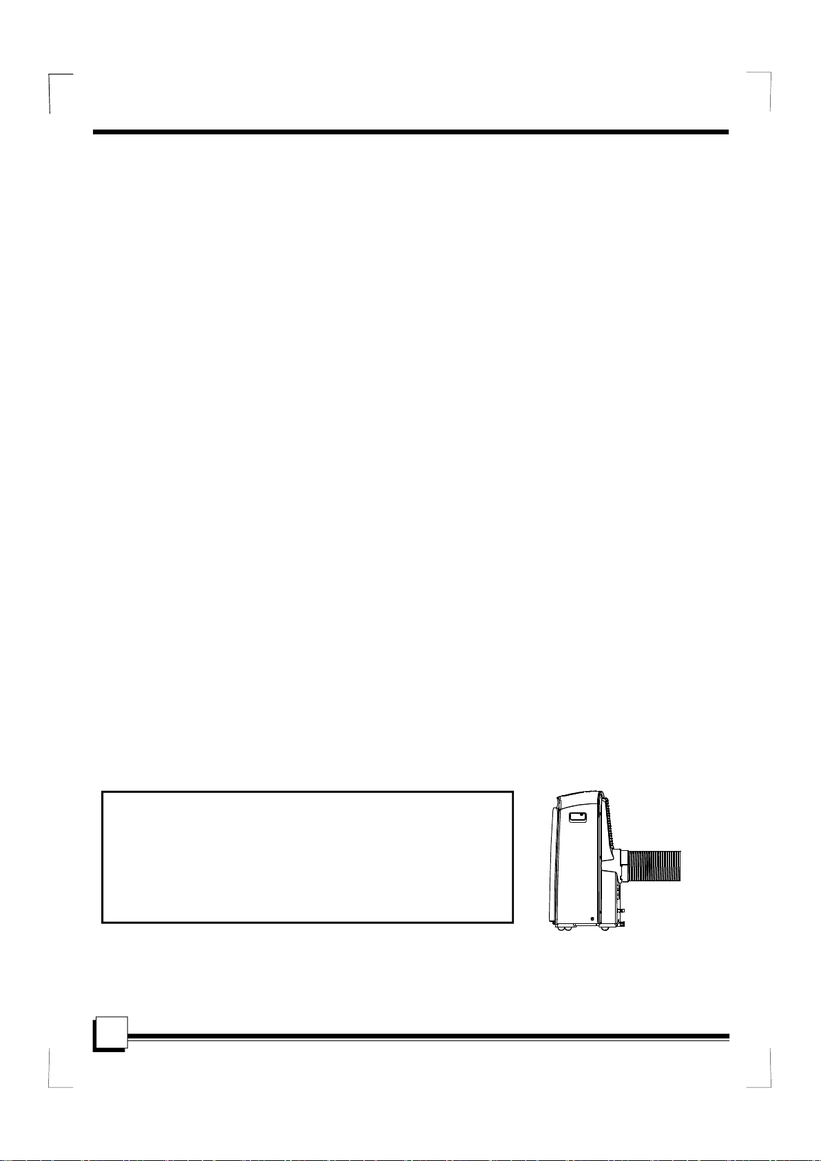
NOT E
The rating data indicated on the energy label is based
on the testing condition of installing the un-extended
air exhaust duct without adaptor A & B (The duct and
the adaptor A & B are listed in the accessories chart
of the Instruction Manual). See the right figure.
1
SOCIABLE REMARK
When using this air conditioner in the European countries, the following information must be followed:
DISPOSAL: Do not dispose this product as unsorted municipal waste. Collection of
such waste separately for special treatment is necessary.
It is prohibited to dispose of this appliance in domestic household waste.
For disposal, there are several possibilities:
A) The municipality has established collection systems, where electronic waste can be
disposed of at least free of charge to the user.
B) When buying a new product, the retailer will take back the old product at least free
of charge.
C) The manufacture will take back the old appliance for disposal at least free of charge
to the user.
D) As old products contain valuable resources, they can be sold to scrap metal dealers.
Wild disposal of waste in forests and landscapes endangers your health when
hazardous substances leak into the ground-water and find their way into the food chain.
CAUTION:
This appliance is not intended for use by persons (including children) with
reduced physical,sensory or mental capabilities, or lack of experience and
knowledge, unless they have been given supervision or instr uction concerning
use of the appliance by a pe rson responsible for their safety.
Children should be supervised to ensure that they do not play with the appliance.
2
SAFETY PRECAUTIONS
Safety r ules
To prevent injury to the user or other people and property damage, the following instructions must be
followed. Incorrect operation due to ignoring of instructions may cause harm or damage.
Always do this
!
Do not operate your air conditioner in a wet room
Your air conditioner should be used in such a way
that it is protected from moisture. e.g. condensation,
splashed water, etc. Do not place or store your air
conditioner where it can fall or be pulled into water
or any other liquid. Unplug immediately.
Always transport your air conditioner in a vertical
position and stand on a stable, level surface during
use.
Turn off the product when not in use.
Always contact a qualified person to carry out
repairs. If the supply cord is damaged it must be
repaired by a qualified repairer.
Keep an air path of at least 30cm all around the
unit from walls, furniture and curtains.
If the air conditioner is knocked over during use,
turn off the unit and unplug from the mains supply
immediately.
such as a bathroom or laundry room.
Do not touch the unit with wet or damp hands or
when barefoot.
Do not press the buttons on the control panel with
anything other than your fingers.
Do not remove any fixed covers. Never use this
appliance if it is not working properly, or if it has
been dropped or damaged.
Never use the plug to start and stop the unit.
Always use the switch on the control panel.
Do not cover or obsturct the inlet or outlet grilles.
Do not use hazardous chemicals to clean or come
into contact with the unit. Do not use the unit in the
presence of inflammable substances or vapour such
as alcohol, insecticides, petrol,etc.
Do not allow children to operate the unit
unsupervised.
Do not use this product for functions other than
those described in this instruction manual.
Energy Save
Use the unit in the recommended room size.
Locate the unit where furniture cannot obstruct the air flow.
Keep blinds/curtains closed during the sunniest part of the day.
Keep the filters clean.
Keep doors and windows closed to keep cool air in and warm air out.
Never do this
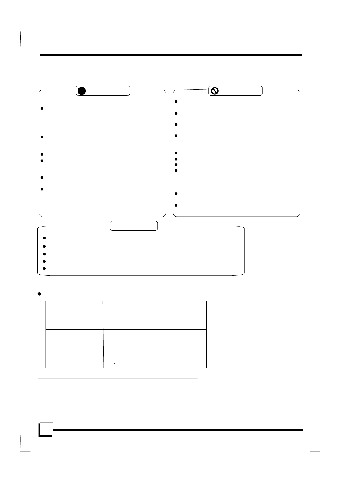
Operating con di tio n
The air conditioner must be operated within the temperature range indicated below:
MODE ROOM TEMPERATURE
COOL
DRY
HEAT(heat pump type)
HEAT(electrical heat type)
O O O O
17 C(62 F)~35
O O O O
13 C(55 F)~35
O O
5 C(41 F)~
O O
<30 C/88 F
O O
30 C(88 F)
C(95 F)
C(95 F)
Suggested tools for window kit installation
1. Screwdri ver( m edi u m s ize Phi llips )
2. Tap e measure or ruler
3. Knife or scissors
4. Saw(In the event that the w indow k it needs to be cu t down in si ze beca use
th e window is too narrow for di rect installati on)
3
IDENTIFICATION OF PARTS
WARNING
Do not store or use gasoline or other flammable vapors and liquids in the vicinity of this or any other
appliance.
Avoid fire hazard or electric shock. Do not use an extension cord or an adaptor plug. Do not remove
any prong from the power cord.
WARNING
Be sure the electrical service is adequate for the model you have chosen. This information can be found
on the serial plate, which is located on the side of the cabinet and behind the grille.
Be sure the air conditioner is properly grounded. To minimize shock and fire hazards, proper grounding is
important. The power cord is equipped with a three-prong grounding plug for protection against shock
hazards.
Your air conditioner must be used in a properly grounded wall receptacle. If the wall receptacle you intend
to use is not adequately grounded or protected by a time delay fuse or circuit breaker, have a qualified
electrician install the proper receptacle.
Ensure the receptacle is accessible after the unit installation.
For your s afety
Electrical Infor mation
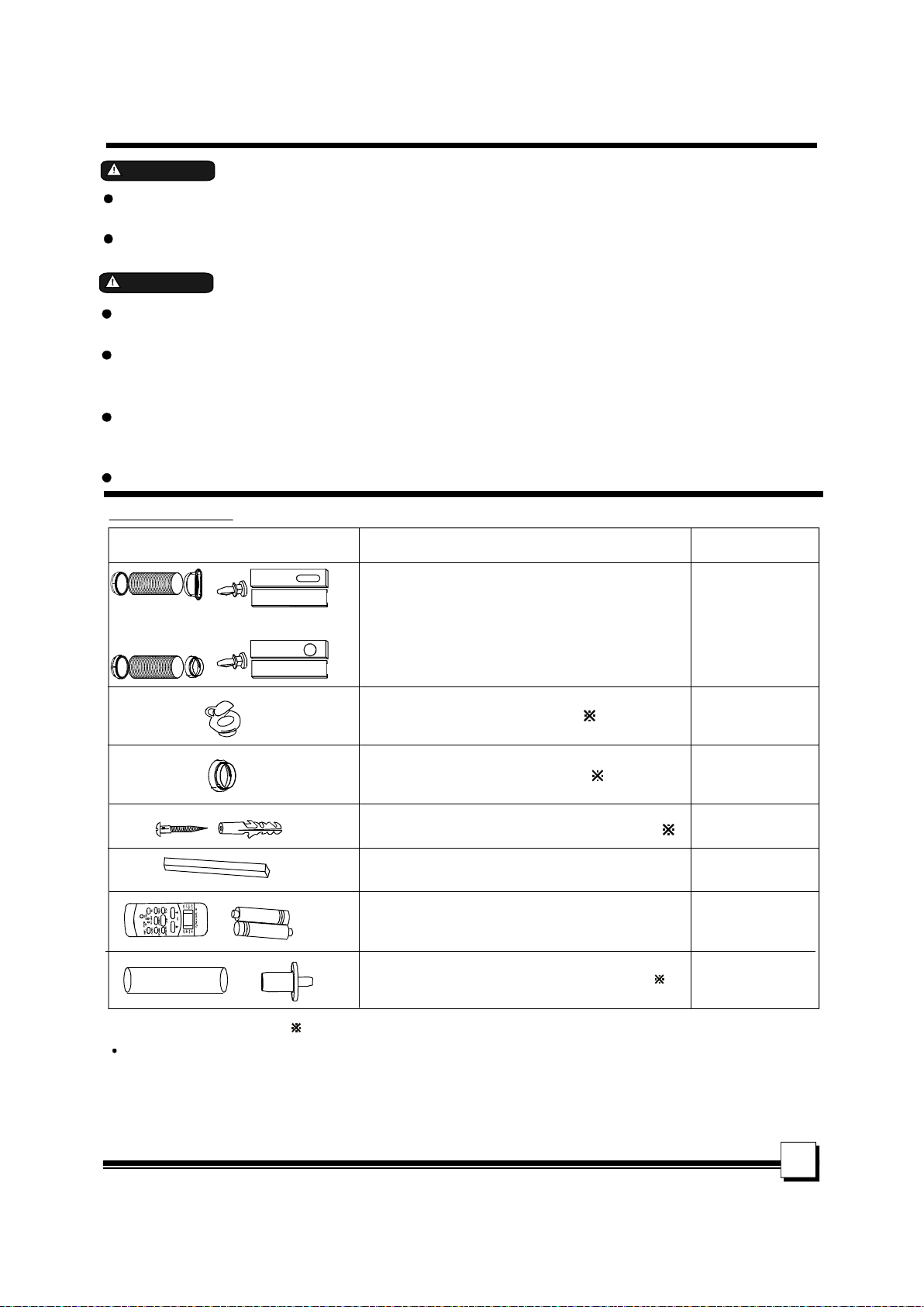
Accessories
PARTS :
or
PARTS NAME :
Exhaust hose and Apaptor and Adaptor B
(flat mouth or round mouth :depending on models)
Window Slider Kit and bolt
I
QUANTITY :
1 set
Wall Exhaust Adaptor A( )
Adaptor B(round mouth)( )
Expansion Plug and wooden screw( )
Foam seal
Remote Controller and Battery
(For remote control models only)
Drain hose and drain hose adaptor( )
NOTE: Op tional pa rt s( ), some mo dels without.
Check all the accessories are included in the package and please refer to the installation instructions for
their usage.
NO TE:
All the illustra t ions i n this manu al are f o r explanation purpose only. Your ai r condition er
may be s lightly different. The ac tual shape s hall prevail.
1 pc
1 pc
4/ pc
3/pc
1pc
1pc
4
IDENTIFICATION OF PARTS
2
1
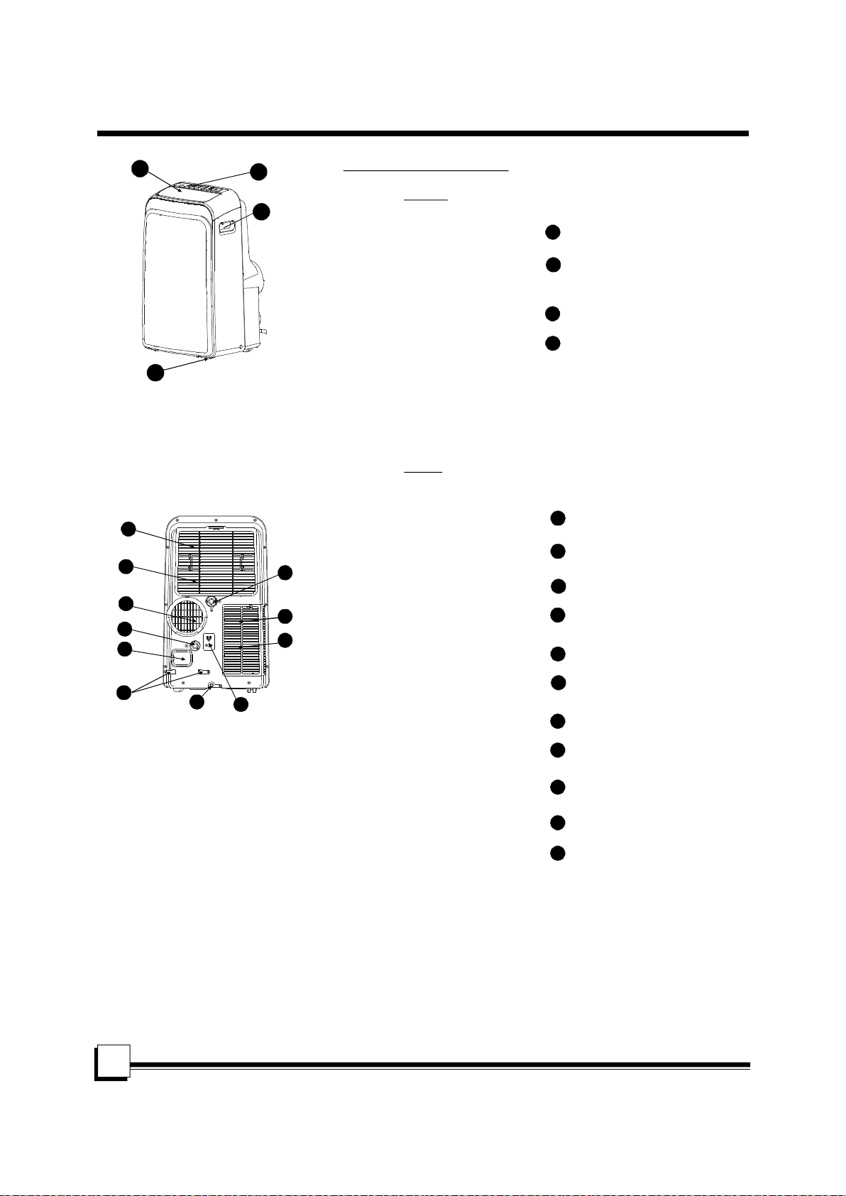
NAMES OF PARTS
Front
4
Operation panel
1
Horizontal louver blade
2
(swing automatically)
Caster
3
Carrying handle
4
(both sides)
3
Fig .1
Rear
Upper air filter
5
6
7
8
9
15
14
13
5
(Behind the grille)
Upper air intake
6
7
Air outlet
Drain outle t ( only fo r Pum p
8
heati n g model)
Po we r cord outlet
9
5
10
11
12
Fig.2
10
Po we r cord buck le (Used
only when st o ri ng the unit )
Bo tto m tra y d ra in ou tlet
11
Po we r plug sock et (Use
12
only when st o ri ng the unit )
Lower air filter
13
(Behind the grille)
Lower air intake
14
15
Drain outle t
AIR CONDITIONER FEATURES
ELEC TRO N IC CONTROL OPER ATIN G IN S T RU C TIO NS
Before you begin , t h oroughly familiariz e yo urself wit h t h e co ntrol panel and rem ote c o ntroller
and all its function s , then follow the s ymbo l f or th e f unc tions you desire.
The u n it ca n be co ntrolled b y the u n it control panel alone o r with the remote co ntroller .
NOTE: This manu al does no t include Re mote Contr oller Operations, see the <<Remote
Contro ll e r I n str ucti on>> pac ked with the unit for d etails.
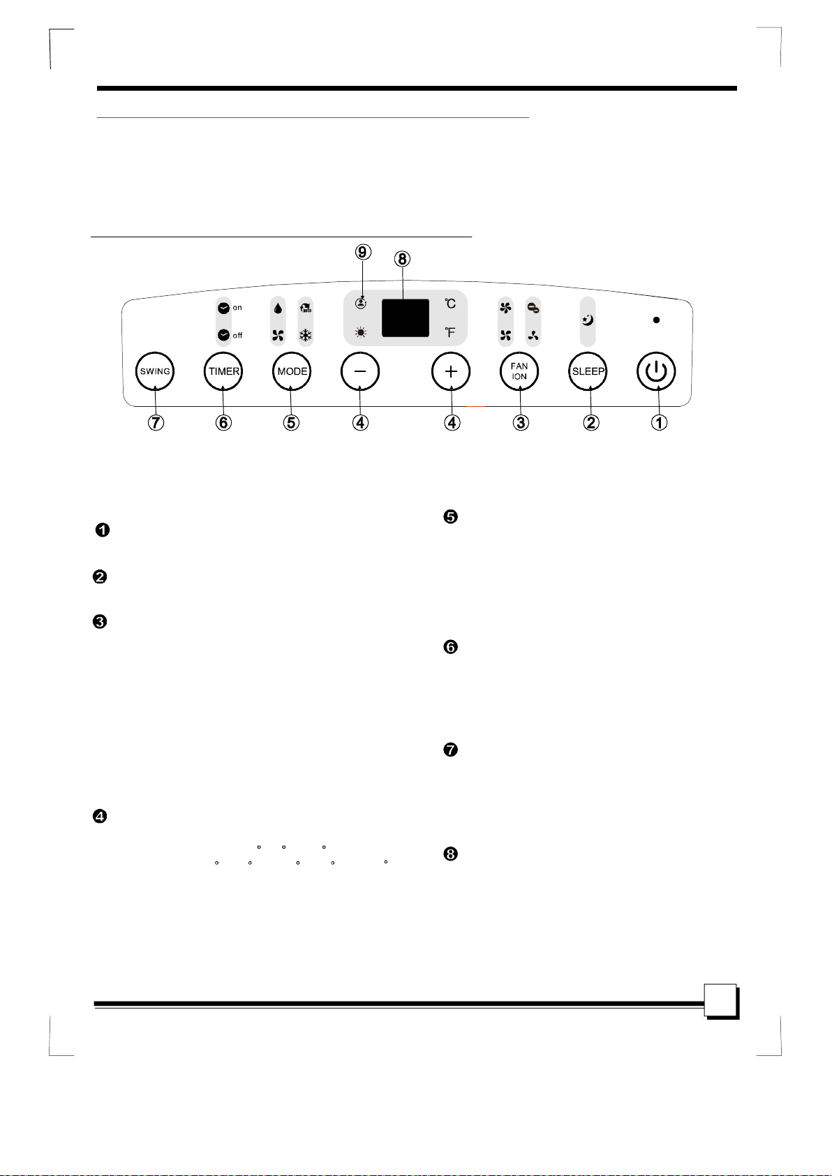
OPERATION PANEL OF THE AIR CONDITIONER
(Optional)
(Op t ional)
NOTE: On some models SLEEP button is instead of ECO button.
POWER button
Power switch on/off.
SLEEP/ECO button
Used to initiate the SLEEP/ECO operation.
FAN/ION button
Control the fan speed. Press to select the fan
speed in four steps-LOW, MED, HI and AUTO.
The fan speed indicator light illuminates under
different fan settings except AUTO speed. When
select AUTO fan speed, all the fan indicator lights
turn dark.
NOTE: Press this button for 3 seconds to initiate
ION feature.The ion generator is energized and will
help to remove pollen and impur ities from the air, and
trap them in the filter. Press it for 3 seconds again to
stop the ION feature.
UP( ) and DOWN( ) button
+
Used to adjust (increasing/decreasing)
temperaturesettingsin1 C/2 F(or 1 F) increments
in a range of 17 C/62 F to 30 C/88 F (or 86 F)
or the TIMER setting in a range of 0~24hrs.
NOTE: The control is capable of displaying
temperature in degrees Fahrenheit or degrees
Celsius. To convert from one to the other, press
and hold the Up and Down buttons at the same
time, for 3 seconds.
(ION is optional)
-
(ION is Optional)
MODE select button
Selects the appropriate operating mode.
Each time you press the button, a mode
is selected in a sequence that goes from
AUTO, COOL, DRY, FAN and HEAT(cooling
only models without). The mode indicator
light illuminates under the different mode
settings.
TIMER button
Used to initiate the AUTO ON start time and
AUTO OFF stop time program, in conjuction
with the & buttons. The timer on/off
indicator light illuminates under the timer
on/off settings.
SWING button
(Applicable to the models with auto swing feature only)
Used to initiate th e Au to swing feature.
When th e operation is ON , press the
SW ING button ca n stop the louv er at
the desired angle.
LED Display
Shows the se t te mperatur e in CO" "
O
" "orF and the Aut o-timer se ttings.
Whi le on DRY and FAN modes, it show s
the ro om tempe rat ure.
+
Fig.3
-
6

OPERATING INSTRUCTIONS
Error codes and p rotection c od e:
E1-
Room temperature sens o r errorUnplug the unit and plug i t back in.
If error r epeats, call for service.
E2-
Evapora t or te mpe ra ture s e ns or err orUnplug the unit and plug i t back in.
If error r epeats, call for service.
E3-
Condenser tempera ture s ensor errorUnplug the unit and plug i t back in. If error
repeats , call for service (on some mod els).
E4-
Displa y panel communicati on
errorUnplug the unit and plug i t back in.
If error r epeats, call for service.
P1-
Bottom tray is ful l - Conn e ct the
drain ho se an d drain the c o llected
water away. If protectio n r e peat s , ca l l
fo r service.
FOLLOW ME/TEMP SENSING feature(optional)
NOTE:This feature can be a ct i vat ed f r om the
rem ote con tro l ON LY. The remote con trol
ser v esas a rem ote the rmo stat allowing f o r th e
pre c is e tem peratu re c o ntr ol at it s location.
To activate the Follow Me/Temp Sensing
featu re, po int the remote control towards
the unit and press the F ollow Me /Temp
Sensing button. T
he remote display is
actu al temperature at its location. The
remo te co n trol will send this signa l to the
air conditioner every 3 minu tes interval
unt il press the Follow Me/Temp Sensing
but to n aga in.
If th e un i t does not r e c eive
the Follow Me/Temp Sensing sig n al during
any 7 minu t es interval , the u nit will beep to
ind i c a te t h e Fo l l ow Me/Temp Se ns ing m o de
has end e d .
Operating Instructions
COOL operation
- Press the "MODE" button until the "COOL"
indicator light comes on.
- Press the ADJUST buttons "+" or " - " to
select your desired room temperature. The
temperature can be set within a range of
O O O O O
17 C-30 C/62 F-88 F (or 86 F).
- Press the "FAN SPEED" button to choose the
fan speed.
HEAT operation(cooling only models without)
- Press the "MODE" button until the "HEAT"
indicator light comes on.
- Press the ADJUST buttons "+" or " - " to
select your desired room temperature. The
temperature can be set within a range of
O O O O O
17 C-30 C/62 F-88 F (or 86 F).
- Press the "FAN SPEED" button to choose the
fan speed. For some models, the fan speed
can not be adjusted under HEAT mode.
- Press the "MODE" button until the "DRY"
indicator light comes on.
- Under this mode, you cannot select a fan
speed or adjust the temperature. The fan
motor operates at LOW speed.
- Keep windows and doors closed for the
best dehumidifying effect.
- Do not put the duct to window.
AUTO operation
- When you set the air conditioner in AUTO
mode, it will automatically select cooling,
heating(cooling only models without), or
fan only operation depending on what
temperature you have selected and the
room temperature.
- The air conditioner will control room
temperature automatically round the
temperature point set by you.
- Under AUTO mode, you can not
select the fan speed.
FAN operation
- Press the "MODE" button until the
"FAN " indicator light comes on.
- Press the "FAN SPEED" button to
choose the fan speed. The temperature
cannot be adjusted.
- Do not put the duct to window.
TIMER operation
- Wh e n the unit is on, pre ss the
Tim er but ton will initiate the Auto-off
stop progra m, the TIMER OFF
indica tor lig h t ill u minates. Pre ss the
UP or down button to select the desir ed
ti me. Press the TIMER button ag ain
within 5 second s , the Aut o-on start
progr am is initiat ed. And the TIMER
ON indicator light i lluminates. Press
the up or down b utton to se l ect th e
desir ed Auto-on start tim e.
-
When the unit is off, pre ss the Timer
butto n to initiate the Au to-o n start
progr am,pr ess it a gain w ithi n five
seconds wil l initiate the Auto-off stop
progr am.
- Press or ho ld the UP or D OWN
butto n to change the Au to tim e by
0.5 hour increments, up to 10 hou rs,
then at 1 hour increm ents up t o 24
hours . The contro l will c ount down
the tim e rem ain i ng unt il sta rt.
- The system wi l l auto matically rever t
back to display the pr evious temperature setting if the re is no operation
in a five seconds per iod.
7
OPERATING INSTRUCTIONS
- Turn ing the un it ON or OFF a t any
time or ad justing the t imer setting
to 0 .0 will cancel the Auto Start/
Stop timer prog ram.
- Wh e n the malfu nction (E1,E2,E3
or E 4) oc c urs , th e Auto Start/St op
timed program will also be c ancelled.
Swing a ut omat ically
SLEE P/ECO operation
Press this button, the selected temperature will
increase(cooling) or decrease(heating) by
O O O
1 30 minutes.The temperature will
C/2 F(or 1 F)
then increase (cooling) or decrease (heating) by
another 1 after an additional 30
O O O
C/2 F(or 1 F)
minutes. This new temperature will be maintained
for 7 hours before it returns to the originally
selected temperature. This ends the Sleep/Eco
mode and the unit will continue to operate as
originally programmed.
NOTE:
This feature is unavailabe under FAN or
DRY mode.
Other features
Auto-Restart(on some models)
If the unit breaks off unexpectedly due to the
power cut,i t will rest art with the previ o us
function se t ting automat icall y when th e
power resumes.
Wait 3 minutes before resuming operation
After the unit h as stopped, it can not be res tarted
opera tion in the first 3 minutes. This is to protect
th e unit. Opera tio n will a utom atically star t afte r
3 minutes.
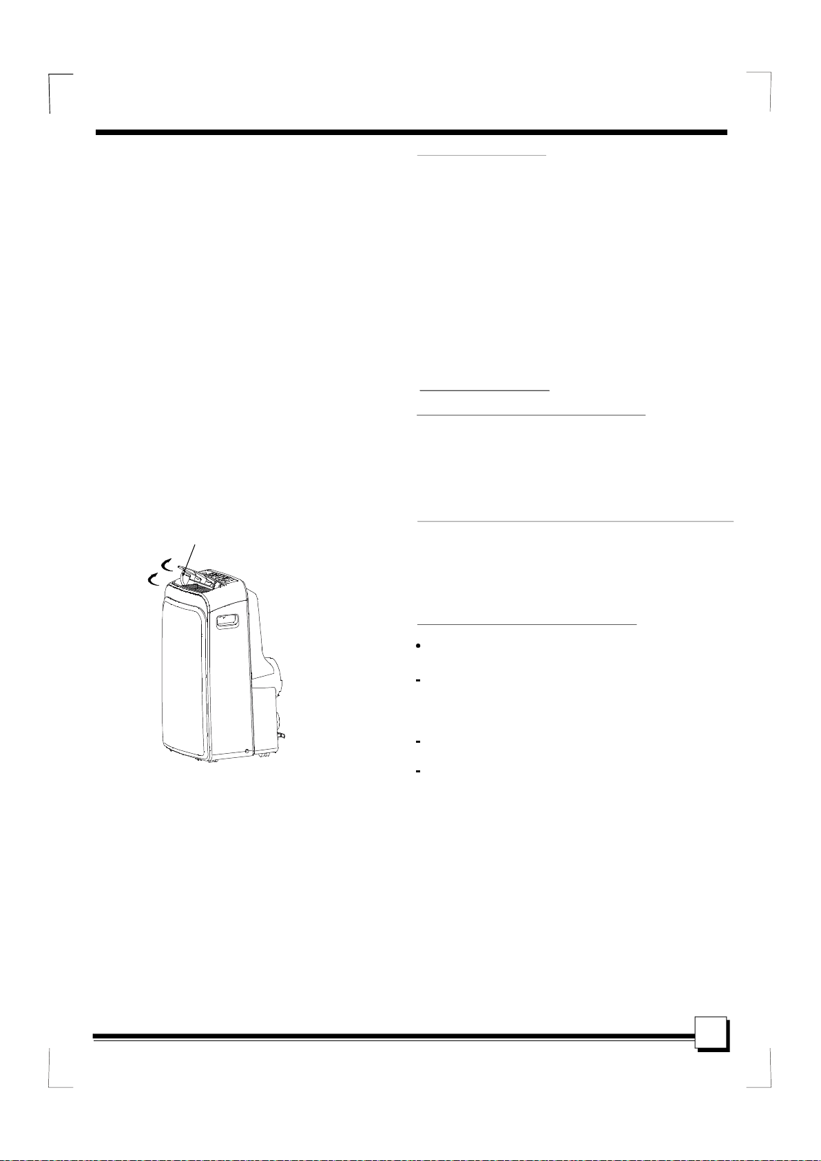
Fig .4
Air flow direction adjustment
Th e lou ver c an be ad just ed automatically .
Adjust th e ai r flow dir ecti on autom ati cally
(Fig.4):
When the Pow er is ON, the louver opens fully.
Press the SWING butto n on the panel or
remo te co ntro ller t o ini tiate the Auto swing
feature.
The louve r willl sw ing u p and do wn
automatic ally.
Pleas e do not adju st th e lou ver man ually.
8
INSTALLATION INSTRUCTIONS(optional)
INSTALLATION INSTRUCTIONS
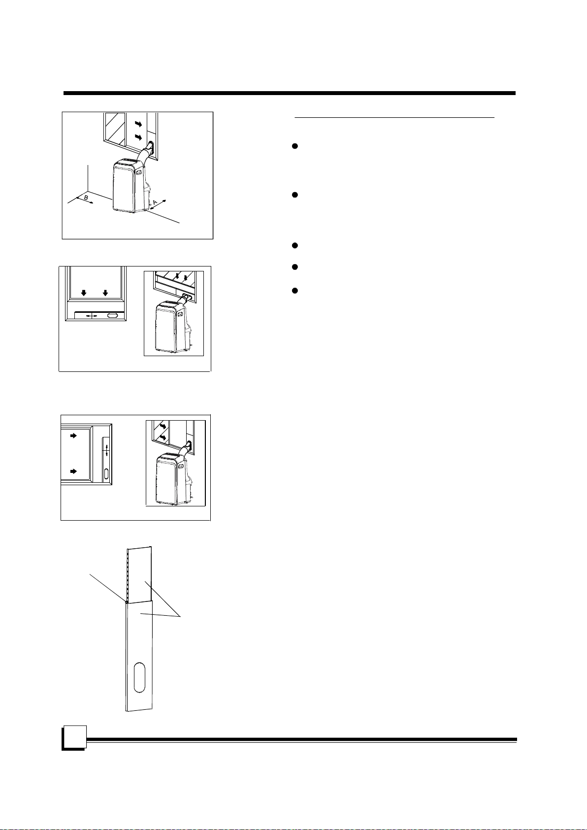
Location
The air conditioner should be placed on a firm
foundation to minimize noise and virbration. For
safe and secure positioning, place the unit on a
smooth, level floor strong enough to support the unit.
The unit has casters to aid placement, but it should
only be rolled on smooth, flat surfaces. Use caution
Fig.5
A: 30c m- 1 00cm B: 30cm≥
when rolling on carpet surfaces. Do not attempt to
roll the unit over objects.
The unit must be placed within reach of a properly
rated grounded socket.
Ho riz on tal
win dow
Never place any obstacles around the air inlet or
outlet of the unit.
Allow 30cm to 100cm of space from the wall with
for efficient air-conditioning.
Window slider kit Installation
Window Sl id er K it
Min im um:67 .5 cm (2 .22 ft ).
Ma xmum: 12 3cm (4 .0 4f t) .
Fig.6
Your window slider kit has been designed to fit most
standard Vertical and horizontal window
applications, However, it may be necessary for you to
improvise/modify some aspects of the installation
procedures for certain types of window. Please refer
to Fig. 6& Fig.7 for minimum and maximum window
openings.Window slider kit can be fixed with a bolt
(see Fig.7a).
" " " "
Hor izon ta l
win dow
Window Sl id er K it
Min im um:67 .5 cm (2 .22 ft ).
Ma xmum: 12 3cm (4 .0 4f t) .
bo lt
9
Fig.7
Window sl id er ki t
Fig.7a
If the window opening is less than the mentioned
Note:
minimum length of the window slider kit, cut that one
with a hole in it short to fit for the window opening.
Do never cut out the hole in window slider kit.
 Loading...