

Page 1

9VSAP-1010-A
SERVICE MANUAL
MIDEA AIRCONDITIONER
On-Off
SPLIT WALL-MOUNTED TYPE
9V SERIES
9220+9221
Page 2

CONTENTS
1. Precaution .................................................................................................................................................... 1
1.1 Safety Precaution .......................................................................................................................... 1
1.2 Warning ......................................................................................................................................... 1
2. Function ........................................................................................................................................................ 6
3. Dimension .................................................................................................................................................... 9
3.1 Indoor Unit ..................................................................................................................................... 9
3.2 Outdoor Unit ................................................................................................................................ 10
4. Refrigerant Cycle Diagram ........................................................................................................................ 11
5. Wiring Diagram .......................................................................................................................................... 12
5.1 Indoor Unit ................................................................................................................................... 12
5.2 Outdoor Unit ................................................................................................................................ 14
6. Installation details ...................................................................................................................................... 18
6.1 Wrench torque sheet for installation ........................................................................................... 18
6.2 Connecting the cables ................................................................................................................ 18
6.3 Pipe length and the elevat ion ..................................................................................................... 18
6.4 Air purging with vacuum pump .................................................................................................... 19
6.5 Pumping down (Re-installation) .................................................................................................. 20
6.6 Re-air purging (Re-installation) ................................................................................................... 22
6.7 Balance refrigerant of t he 2-way, 3-way valves .......................................................................... 23
6.8 Evacuation .................................................................................................................................. 24
6.9 Gas charging ............................................................................................................................... 25
7. Operation characteristics ......................................................................................................................... 26
8. Electronic function .................................................................................................................................... 27
8.1 Abbreviation ................................................................................................................................ 27
8.2 Display function ........................................................................................................................... 27
8.3 Main Protection ........................................................................................................................... 28
8.4 Operation Modes and Functions ................................................................................................. 28
9. Troubleshooting ......................................................................................................................................... 37
9.1 Indoor Unit Error Display ............................................................................................................. 37
9.2 Diagnosis and Solution ............................................................................................................... 38
Page 3

1
1. Precaution
1.1 Safety Precaution
To prevent injury to the user or other people and pro perty damage, the following
instructions m us t be followed.
Incorrect operation due to ignoring instruction will cause harm or da mage.
Before service unit, be sure to read this service manual at f i r st.
1.2 Warning
Installation
Do not use a defective or underr at ed circuit breaker. Use this appli ance on a dedicated
circuit.
There is risk of fire or electric shock.
For electrical work, contact the dealer, seller, a qualified el ect rician, or an Authorized
service center.
Do not disassemble or repair the product, there is risk of fire or electric shock.
Always ground t he product.
There is risk of fire or electric shock.
Install the panel and the cover of co ntr ol box securely.
There is risk of fire of electric shock.
Always instal l a dedicated circuit and breaker.
Improper wiring or installation may cause fore or electric shock.
Use the correctly rated breaker of fuse.
There is risk of fire or electric shock.
Do not modify or extend the power c able.
There is risk of fire or electric shock.
Do not install, remove, or reinstall the unit by yourself(customer).
There is risk of fire, electric shock, explosion, or injury.
Be caution when unpacking and installing the product.
Page 4

2
Sharp edges could cause injur y, be especially careful of the case edges and t he f ins on the
condenser and evaporator.
For installation, always contact th e dealer or an A ut hori zed service center.
There is risk of fire, electric shock, explosion, or injury.
Do not inst all the product on a defective installation stand.
It may cause injury, accident, or dam age to the product.
Be sure the install ation area does not deteriorate with age.
If the base collapses, the air conditioner could fall with it, causing property damage, product failure,
and personal injury.
Do not let the air conditioner run for a long time when the humidity is very high and a
door or a windo w is le ft open.
Moisture may condense and wet or damage furniture.
T ake care to ensure that power cable could not be pull e d out or damaged dur ing
operation.
There is risk of fire or electric shock.
Do not place any t hing on the power cable.
There is risk of fire or electric shock.
Do not plug or unplug t he power supply plug during operat i on.
There is risk of fire or electric shock.
Do not touch (operation) the product with wet hands.
There is risk of fire or electric shock.
Do not place a heater or other appliance near the power cable.
There is risk of fire and electr ic shock.
Do not allow water to run into electric parts.
It may cause fire, failure of the product, or electric shock.
Do not store or use flammable gas or combustible near the product.
There is risk of fire or failure of product.
Do not use the pro duc t in a tightly clos ed space for a long time.
Oxygen deficiency could occur.
When flammabl e gas leaks, turn off t he gas and open a window for ventilat ion before
turn the product on.
Page 5

3
Do not use the telephone or t ur n sw it ches on or off.
There is risk of explosion or fire.
If strange sounds, or small or smoke comes from product. Turn the breaker off or
disconnect the power supply cable.
There is risk of electric shock or fire.
Stop operation and close the window in storm o r hur ricane. If possible, r em ove the
product from the window before the hurricane arrives.
There is risk of property damage, failure of product, or electric shock.
Do not open the inle t gril l of the produ ct duri ng o peratio n. (Do not to uch the el ectr ost at ic
filter, if the unit is so equipped.)
There is risk of physical injury, electric shock, or product failure.
When the product is soaked (flooded or submerged) , contact a n Author i z ed s er vice
center.
There is risk of fire or electric shock.
Be caution that water could not enter the product.
There is risk of fire, electric shock, or product damage.
Ventilate the product from time to time when operating it together with a stove, etc.
There is risk of fire or electric shock.
Turn the main po wer off when cleaning or maintaining the product.
There is risk of electric shock.
When the product is not be used for a l ong time, disco nnect the power supply plug or
turn off the breaker.
There is risk of product damage or failure, or unintended op er at io n.
Take care to ensure that nob ody could step on or fall onto the outdoor unit .
This could result in person al in jury and product damage.
CAUTION
Always check for gas (refri ger ant) leakage after installation or re pair of product.
Low refrigerant levels may cause failure of product.
Install the drain hose to ensure that water is drained away properly.
Page 6

4
A bad connection may cause water leakage.
Keep level even when installing the product.
To avoided vibration of w ater leakage.
Do not install the product where the noise or hot air from the outdoor unit could damage
the neighborho ods.
It may cause a problem for your neighbors.
Use two or more people to lift and transport t he pr oduct.
Avoid personal injury.
Do not install the product where it will be exp osed to sea wind (salt spray ) di r ect ly.
It may cause corrosion on the pr oduct . Corrosion, particu larly on the condenser and evaporat or fins,
could cause product malfunction or inefficient operation.
Operational
Do not expose th e sk i n directly to cool air for long periods of t ime. (Do not sit in the
draft).
This could harm to your health.
Do not use the product for special purp oses, such as preser ving fo ods, works of art, etc.
It is a consumer air conditioner, not a precision refrigerant system.
There is risk of damage or loss of property.
Do not block the inlet or outlet of air flow.
It may cause product failur e.
Use a soft cloth to clean. Do not use harsh detergen ts, solvents, etc.
There is risk of fire, electric shock, or damage to the plastic par ts of the product.
Do not touch the metal parts of the product when removing the air filter . They are very
sharp.
There is risk of personal injury.
Do not step on or p ut anything on the pro duct. (out door units)
There is risk of personal injury and f ailure of product.
Always insert the filt er securely. Clean the filter every two weeks or mor e often if
necessary.
Page 7

5
A dirty filter r educes the efficiency of the air conditioner and could cause product malfunction or
damage.
Do not insert hands or other object t hrough air inlet or out let while the p r oduct is
operated.
There are sharp and moving parts that could caus e pers onal injury.
Do not drink the water drained from the product.
It is not sanitary could ca use serious health issues.
Use a firm stool or ladder when clea ning or maintaining the produc t .
Be careful and avoid personal injury.
Replace the all batteries i n t he rem ote control with new ones of the same type. Do not
mix old and mew batteries or different types of batteries.
There is risk of fire or explosion.
Do not recharge or disassemble the batteries. Do not di spose of batteri es in a fire.
They may burn of explode.
If the liquid from the batteries gets onto your s kin or clothes, was h it well with clean
water. Do not use the remote of the batt er i es have leaked.
The chemical in batteries could cause burns or other health hazards
Page 8
6
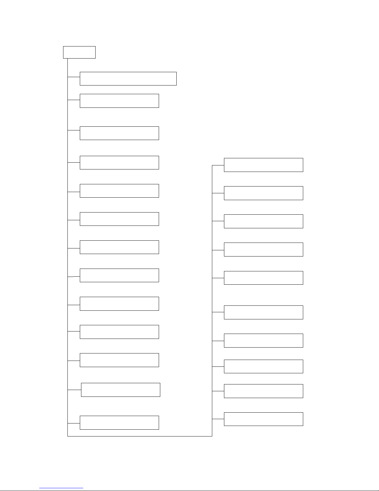
2. Function
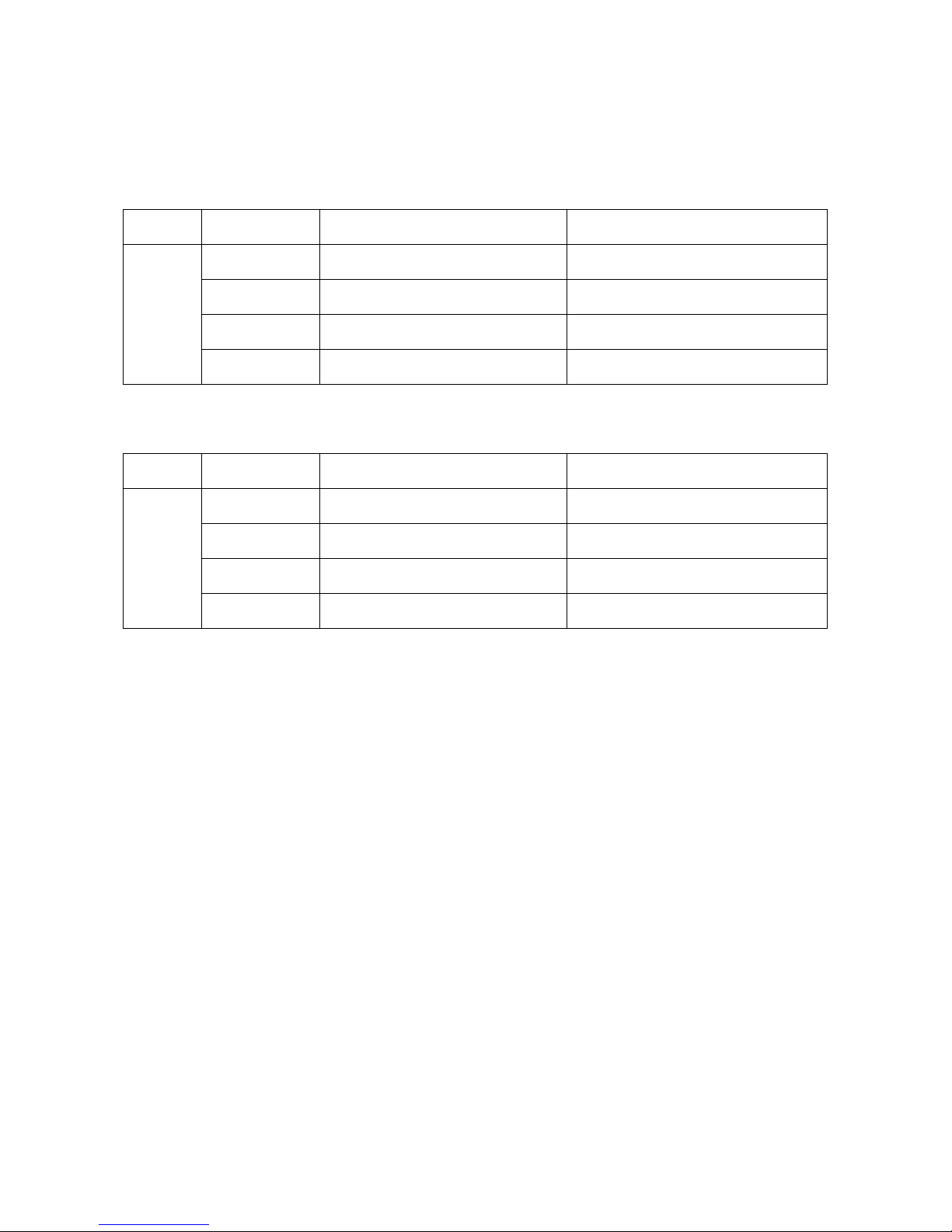
Model Names of Indoor/Outdoor Units
Cooling only:
Series Capacity Indoor units Outdoor units
On-Off
7k MS9V-07CR-QB6 MOK2-07C-QB6
9k MS9V-09CR-QB6 MOK6-09C-QB6
12k MS9V-12CR-QB6 MOA1-12C-QB6
18k MS9V-18CR-QB MOB-18C-QB6
Cooling & Heating
Series Capacity Indoor units Outdoor units
On-Off
7k MS9V-07HR-QB6 MOK-07H-QB6
9k MS9V-09HR-QB6 MOK3-09H-QB6
12k MS9V-12HR-QB6 MOB-12H-QB6
18k MS9V-18HR-QB6 MOB-18H-QB6
Page 9
7
Temp. Compensation
The mode can be change by the room
temperature.
Auto mode
Easy clean panel
Indoor unit
Operation ON/OF by remote controller
Sensing by room temperature
Room temperature contr ol
Starting temperature co ntrol
Time Delay Safety control
Indoor fan speed control
Two-direction air vane
Sleep mode auto control
Independent dehumidification
Air flow Direction control
Anti-cold functio n
Room temperature sensor.
Pipe temperature sensor.
Maintain the room temperature in accordance with
the setting temperature.
Indoor fan is delayed for 5 sec at the starting
Restarting is for approx. 3 minutes..
Auto Restart Function
High, med, low, auto.
The unit will decide the louver direction according
to operation mode.
The fan is turn to low speed (cooling/heating).
The function is usually used in rainy days in
springtime or damp areas.
The louver can be set at the des i re d pos ition
or swing up and down automatically
Self-diag. function
Timer function
Follow me
Self-cleaning
Prevent the cold wind at the beginning of unit
start.
Auto defrost
Flexible wiring connection
When the power supply is interr upted and then
restore, the air conditioners automatically
restore the previous function setting
Ionizer (optional)
Indoor golden fin (optional)
Page 10

8
It protects the valv es and pr events water from
dripping.
The unit has 3 min delay between co nt inuously ON/OFF
operations.
Outdoor unit
Power relay control
The hydrophilic fin can impr ove the heating efficiency at operation
mode.
Hydrophilic aluminum fin for heat pump models
It is only operated in the heatin g oper ation mode except defrosting
operation.
Anti-rust cabinet
Valv e pr otect i on cover
4 way valve control for heat pump models
Made from electrolytic zin c s t eel sheet and anti-rust coated
components.
Low noise air flow syst em
Bird tail propeller fan m akes the outdoor unit run more
quietly.
Page 11
9
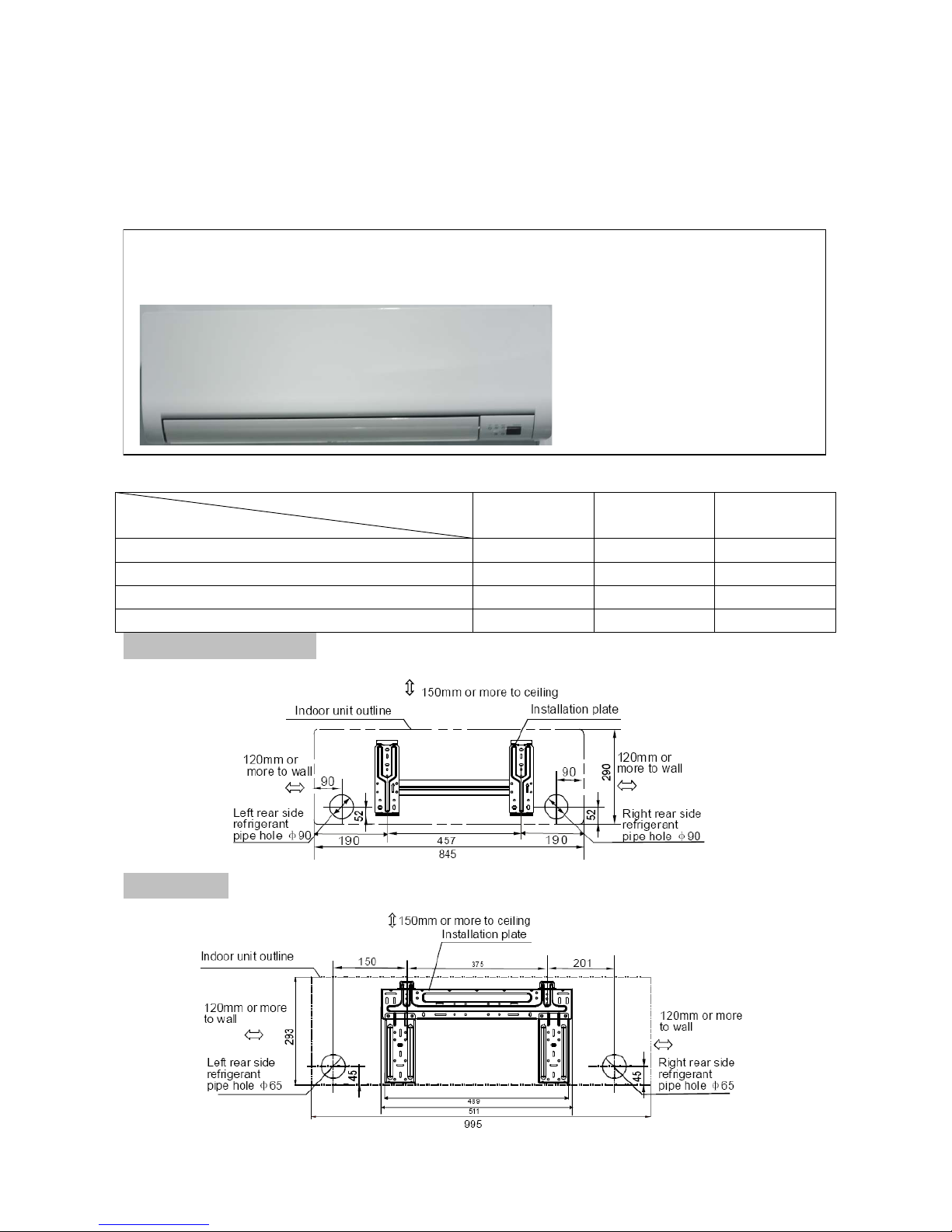
3. Dimension
3.1 Indoor Unit
Dimension
Mode
W H D
MS9V-07CR-QB6/MS9V-07HR-QB6 845 290 165
MS9V-09CR-QB6/MS9V-09HR-QB6 845 290 165
MS9V-12CR-QB6/MS9V-12HR-QB6 845 290 165
MS9V-18CR-QB+MS9V-18HR-QB6 995 292 200
For smaller than 18K model:
For 18K model:
Page 12
10
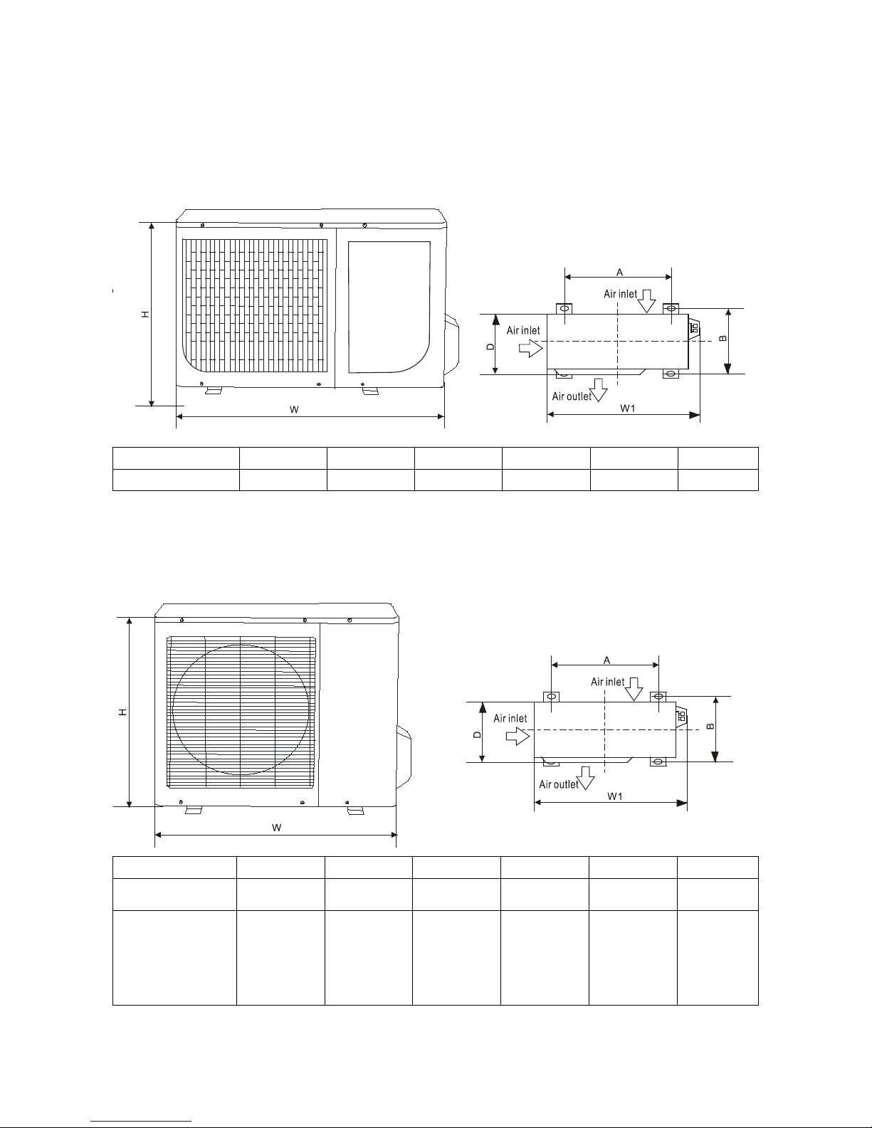
3.2 Outdoor Unit
MOK2-07C-QB6 MOK-07H-QB6 MOK6-09C-QB6 MOK3-09H-QB6
Dimension Mode
W D H
W1 A B
7K、9K
685 260 430 742 460 276
MOA1-12C-QB6 MOB-12H-QB6 MOB-18C-QB6 MOB-18H-QB6
Dimension Mode
W D H
W1 A B
MOA1-12C-QB6
700 235 535 760 458 250
MOB-12H-QB6
MOB-18C-QB6
MOB-18H-QB6
780 250 540 838 549 276
Page 13
11
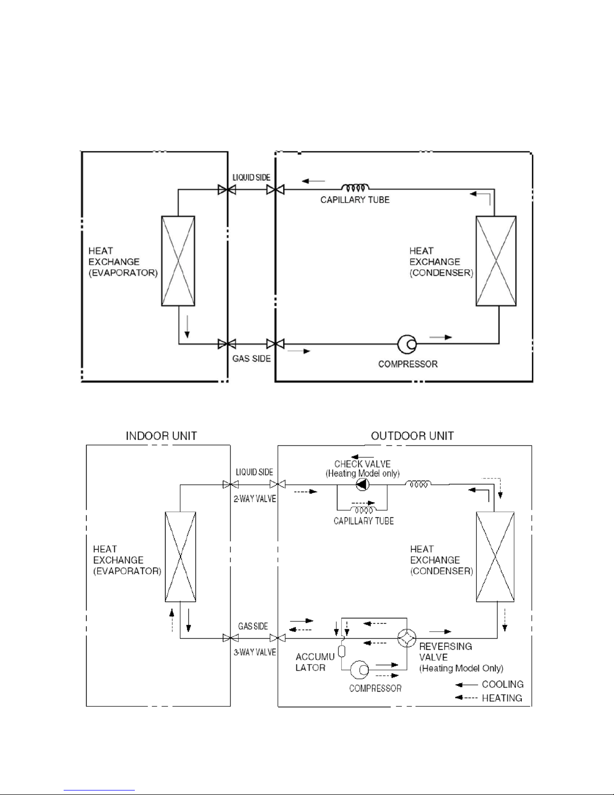
4. Refrigerant Cycle Diagram
Cooling only:
Heat pump mode:
Page 14

12
5. Wiring Diagram
5.1 Indoor Unit
Cooling only:
Page 15

13
Cooling & Heating:
Page 16

14
5.2 Outdoor Unit
Smaller than 18K model:
Cooling only:
Page 17

15
Cooling & Heating:
Page 18

16
For 18 K model:
Cooling only:
Page 19

17
Cooling & Heating:
Page 20

18
6. Installatio n details
6.1 Wrench torque sheet for installation
Outside diameter Torque Additional tightening torque
mm inch N·cm N·cm
Ф6.35 1/4
1500
(153kgf.cm)
1600
(163kgf.cm)
Ф9.53 3/8
2500
(255kgf.cm)
2600
(265kgf.cm)
Ф12.7 1/2
3500
(357kgf.cm)
3600
(367kgf.cm)
Ф16 5/8
4500
(459kgf.cm)
4700
(479kgf.cm)
6.2 Connecting the cables
The power cord of connect should be selected according to the following specifications sheet.
Grade
Unit
7K 9K 12K 18K
mm2
1.5 1.5 1.5 2.5
6.3 Pipe length and the elevation
Capacity
Btu/h
Pipe size Standard
length
(m)
Max.
Elevation
B (m)
Max.
Length
A (m)
Additional
refrigerant
(g/m)
Gas Liquid
7K 3/8’’ (Ф9.52) 1/4’’ (Ф6.35) 5 5 10 30
9K 3/8’’ (Ф9.52) 1/4’’ (Ф6.35) 5 5 10 30
12K 1/2’’ (Ф12.7) 1/4’’ (Ф6.35) 5 5 10 30
18K 1/2’’ (Ф12.7) 1/4’’ (Ф6.35) 5 8 15 30
Page 21

19
Caution:
Capacity test is based o n standard length and max i mu m al low ance length is based on relia bi lity.
Oil trap should be install ed per 5-7 meters.
6.4 Air purging with vacuum pump
Air and moisture in the refrigerant system have undesirable effects as below:
● Pressure in the system rises.
● Operating current rises.
● Cooling or heating efficienc y drops.
● Moisture in the refrigerant circuit m ay freeze and block capillary t ubing.
● Water may lead to corrosi on of parts in the refrigera nt s ystem.
Therefore, the indoor units and the pipes between indoor and outdoor units must be leak tested and
evacuated to remove gas and moisture from the system.
Air purging with vacuum pump
(Indoor unit)
(Liquid side)
(Gas side)
Vacuum
pump
Vacuum
pump
adaptor
Lo
Hi
Handle Hi
Two-way valve
Close
Manifold valve
Compound meter
Pressure
gauge
-76cmHg
Handle Lo
Charge hose
Charge hose
(Outdoor unit)
Close
Three-way valve
Page 22

20
1. Completely tighten the flare nuts of the indoor and outdoor units, connect the manifold valve
charge.
2. Connect the charge hose connection to the vacuum pump.
3. Fully open the handle Lo of the ma nifold valve.
4. Operate the vacuum pump to evacuate. Af t er starting evacuation, slight ly loose the flare nut of the
Lo valve on the gas pipe side and check the air is entering. (Operation noise of the vacuum pump
changes and a compound meter indicates 0 stead of minutes)
5. After the evacuation is complete, fully close the handle Lo valve of the ma ni fold valve and stop the
operation of the vacuum pump. M ake evac uation for 15 minut es or mor e and c heck the co mpoun d
meter indicates -76cmHg.
6. Turn the stem of the Hi valve about 45°counterclockwise for 6 or 7seconds after the gas coming
out, then tighten the flare nut again. Make sure the pressure display in the pressure indicator is a
little higher than the atmosphere pressure.
7. Remove the charge hose from the Lo pressure charge hose.
8. Fully open the Hi and Lo p acked valve.
9. Securely tighten the cap of the packed valve.
Gas leak check
Soap water method
Apply soap water or a liquid neutral detergent on the indoor unit connections or outdoor unit
connections by a soft brush to check for leakage of the connecting points of the piping. If bubbles
come out, the pipes have leakage.
6.5 Pumping down (Re-installation)
Page 23

21
Produce
1. Confirm that both the 2-way and 3-way valves are set to the opened p osition.
Remove the valve stem caps and confirm that the valve st ems are in the opened position.
Be sure to use a hexagonal wrench to operate the valve stems.
2. Operate the unit for 10 to 15 minut es.
3. Stop oper ation and wait for 3 minutes, then connect the charge set to the service port of the 3-way
valve.
Connect the charge hose w it h t he push pin to the gas service port.
5. Air purging of the charge hose.
Open the low-pressure val ve on the charge set slightly to purge air from the charge hose.
6. Set the 2-way valve to the clo se position.
7. Operate the air conditioner at t he cooling cycle and stop it when the gauge indicates 0.1MPa.
8. Immediately set the 3-w ay valve to the closed position.
Do this quickly so that the gaug e ends up indicating 0.3 to 0.5Mpa.
Disconnect the charge set, and amount the 2-way and 3-way valve’s stem nuts and ser vice port caps.
Use a torque wrench to tight en t he ser vice port cap.
Be sure to check for gas lea kage.
Page 24

22
6.6 Re-air purging (Re-installation)
Procedure:
1. Confirm that both the 2-way and 3-way valves are set to the closed position.
2. Connect the charge set and a char ging cylinder to the service port of the 3-way valve.
Leave the valve on the chargin g cylinder closed.
3. Air purging.
Open the valves on the charging cylinder and the charge set. Pur ge the air by loosening the flare nut on
the 2-way valve approxim at ely 45’ for 3 seconds then closing it for 1 minute; repeat 3 ti me s.
After purging the air, use a torque wrench to tighten the flare nut to on the 2-way valve.
4. Check the gas leakage.
Check the flare connections for gas leakage.
5. Discharge the refrigerant.
Close the valve on the charging cy linder an d dischar ge the re frigerant unt il the gaug e indicates 0. 3 to 0.5
Mpa.
6. Disconnect the charge set and the charging cylinder, and set t he 2-way and 3-way valves to the ope n
position.
Page 25

23
Be sure to use a hexagonal wrench to operate the valve stems.
7. Mount the valve stems nuts and the service port cap.
Be sure to use a torque wrench to t ighten the service port cap to a torque 18N.m.
Be sure to check the gas leakage.
6.7 Balance refrigerant of the 2-way, 3-way val ves
Procedure:
1. Confirm that both the 2-way and 3-way valves are set to the open pos it io n.
2. Connect the charge set t o t he 3-way valve’s service port .
Leave the valve on the charge s et cl os ed.
Connect the charge hose w it h t he push pin to the service port.
3. Open the valves (Low side) on the c har ge set and discharge the refriger ant until the gauge indicates
0.05 to 0.1Mpa.
If there is no air in the refrigerat io n c ycle the pressure when the air conditioner is not running is higher
than 0.1Mpa, discharg e the refrigerant until the gauge ind icat es 0.05 to 0.1 Mpa. In t his case, it will not
be necessary to apply an ev acuat ion.
Discharge the refrigerati on gradually; if it is discharged t oo s uddenly, the refrigeratio n oi l will be
discharged.
Page 26

24
6.8 Evacuation
Procedure:
1. Connect the vacuum pump to the charge set’s centre hos e.
2. Evacuation for approximately one hour.
Confirm that the gauge ne edl e has moved toward -0.1 Mpa (-76 cmHg) [vacuum of 4 mmHg or less].
3. Close the valve (Low side) on t he charge set, turn off the vacuum pump, and confirm that t he gauge
needle does not move (appr oximately 5 minutes after turning off the vacuum p um p) .
4. Disconnect the charge hose from the vacuum pump.
Vacuum pump oil, if the vacuu m p ump oil becomes dirty or depleted, r eplenish as needle.
Page 27

25
6.9 Gas charging
Procedure:
1. Connect the charge hose to t he char ging cylinder.
Connect the charge hose w hich you disconnected from the vacuum pump to the valve at t he bottom of
the cylinder. If the refrigerant is R 410A, make the cylinder bottom up to ensure liquid charge.
2. Purge the air from the charge hos e.
Open the valve at the bott om of th e cy linder a nd pr ess t he ch eck v alve on t he charge set to purg e t he air
(be careful of the liquid refrigerant).
3. Open the valves (Low side) on the c har ge set and charge the system wit h l i quid refrigerant.
If the system cannot be charge with the spec ified am ount of refriger ant, if can be charge d with a little at a
time (approximately 150g each time0 whi le o per at ing the air conditioner in the c ool ing cycle; however,
one time is not sufficient, wait approximately 1 minut e and t hen r epeat the procedure.(pu mp ing
down-pin).
4. Immediately disconnect the charge hose from the 3-w ay valve’s service port.
Stoppin g partway will allow the r efrigerant to be discharged.
If the system has been charged w ith liquid refrigerant while operat ing the air conditioner, turn off the air
conditioner before disconnecting the hose.
Page 28

26
5. Mounted the valve stem caps and the service port
Use torque wrench to tight en t he ser vice port cap to a torque of 18N.m.
Be sure to check for gas lea kage.
7. Operation characteristics
Mode
Temperature
Cooling operation
Heating
operation
Drying operation
Room temperature
17℃~32℃ 0℃~30℃
10℃~32℃
(<21000Btu/h models)
17℃~32℃
(≥21000Btu/h models)
Outdoor
temperature
18℃~43℃
(-5℃~43℃:For the models w ith
low temperature cooling s ystem)
(21℃~52℃:For special tropical
models)
-7℃~24℃
11℃~43℃
(<21000Btu/h models)
18℃~43℃
(≥21000Btu/h models)
21℃~52℃
(For special tropical
models)
CAUTION:
1. If air conditioner is used outside o f t he above conditions, certain safety protection features may
come into operation and cause t he unit to function abnormally.
2. Room relative humid ity less tha n 80%. I f the air c onditioner operat es in exce ss of this figure, t he
surface of the air conditioner may attract condensation. Please sets the vertical air flow louver to its
maximum angle (vertically to the floor), and set HIGH fan mode.
3. Optimum performance w ill be ac hieved within this operating temperature.
Page 29

27
8. Electronic function
8.1 Abbreviation
T1: Indoor ambient temperat ur e
T2: Pipe temperature of indoor heat exchanger
Ts: Set temperature
8.2 Display function
8.2.1 Icon explanation on indoor display board:
Run indicator
Flash at 0.5Hz when the unit is standby. Illuminate when the unit is turned on.
Auto indicat or
This indicator illuminates when the air conditioner is in AUTO operation.
Timer indicator
This indicator illuminates when TIMER is set ON/OFF.
Defrost Indicator
This indicator illuminates when the air conditioner starts defrosting automatically or when the
warm air control feature is activated in heating mode
TURBO operation display
Illuminated when select TURBO function in cooling operation or in heating operation.
TEMPERATURE indicator
Usually it displays the temperature settings. When change the setting temperature, this
indicator begins to flash, and stops 20 seconds later. It displays the room temperature when
the air conditioner is in FAN only operation, and the range of that is 0~50℃. It will also
display the error codes when malfunction or protection happen.
8.2.2 LED display control function.
Pressing “LED display” button on remote controller will turn off all displays on indoor unit, while pressing
once again, all displays will resume.
Page 30

28
8.3 Main Protection
8.3.1 Time Delay at restart for compressor.
8.3.2 Current protection
The following chart shows t he pr otection if the current was too high.
While
I
Restore
= 4.5A, I
Fan
= 5.5A , I
5Min
= 6.5A
,
I
3Sec
= 7.5A for 7K model;
I
Restore
= 5.0A, I
Fan
= 6.5A , I
5Min
= 7.5A
,
I
3Sec
= 10A for 9K model;
I
Restore
= 8A, I
Fan
= 9.5A , I
5Min
= 10.5A
,
I
3Sec
= 12A for 12K model;
I
Restore
= 12A, I
Fan
= 14A , I
5Min
= 15A
,
I
3Sec
= 17A for 18K model;
8.3.3 Fan Spee d i s out of control.
When indoor fan speed is too low (lower than 300RPM for 50 seconds), the unit stops and LED
displays failure
8.4 Operation Modes and Functions
8.4.1 Fan only mode.
(1) Outdoor fan and co mp r essor st op.
(2) Temperature setting function is disabled, and no setting temperature is display.
(3) Indoor fan can be set to high/med/low / auto.
(4) The louver operates the same as in cooling mode.
(5) Aut o fa n:
Page 31

29
8.4.2 Cooling Mode
8.4.2.1 Compressor and outdoor fan control
The action of the compressor and t he outdoor fan are submitted to the following rule:
8.4.2.2 Indoor fan running rules
In cooling mode, indoor fan runs all the time and the speed can be selected in high , m edi um , low and
auto speed.
Auto fan in cooling mode act s as f ollow:
8.4.2.3 Evaporator low t emper ature T2 prot ectio n.
When T2<TE5 continuous for 5 min, the compressor and outdoor fan will stop and restart until
T2>TE6.
Page 32

30
While TE5 = 4℃ ,TE6 = 10℃ for 7k 、9K、12K model
While TE5 = 3℃ ,TE6 = 12℃ for 18k model
8.4.3 Heating Mode
8.4.3.1 Compressor an d outdoor fan running rules
Each startup of the compressor, it will work for 7min unconditionally, then the compres sor and outdoor
fan will be controlled by the temperature difference between T1 and Ts. When T1-Ts>3℃, the
compressor and outdoor fan will stop and restart until T1-Ts ≤2℃. During the 7min operation, all the
protections are valid.
8.4.3.2 Indoor fan running rules:
Indoor fan speed can be selecte d in high, medium, low and aut o.
8.4.3.2.1 Indoor fan runni ng r ule in anti-cold wind function m ode
The anti-cold wind function is controlled by the evaporator temperature, refer the principle to the
following chart:
For smaller than 18K model:
26
30
28
32
For 18k model:
8.4.3.2.2 Auto fan action in heating mod e.
Page 33

31
When T1-Ts≤0℃, transfer t o med iu m sp eed,
When T1-Ts>2℃, transfer to low speed.
8.4.3.3 Defrosting mode:
Condition of defrosting:
If any one of following items is sat i sfied, defrosting will start.
Condition 1: Both the following conditions are satisfied:
A: If the working time of the compressor accumulates to 42 min and one continuous
working time is more than 390s.
B: Check the temperature difference between T2 and T1
℃
Fan speed
T2-T1 Note
High
<
TH
DEFROST
If indoor fan is in high speed and T2-T1< TH
DEFROST
, start defrosting
Medium
<TM
DEFROST
If indoor fan is in medium speed and T2-T1<1 TM
DEFROST
,
start defrosting
Low
<
TL
DEFROST
If indoor fan is in low speed and T2-T1<
TL
DEFROST
, start defrosting
Breeze or indoor
fan stop
/
If indoor fan is breezing or stopped, start defrosting
While TH
DEFROST
= 14℃ ,TM
DEFROST
= 15℃, TL
DEFROST
= 16℃ for 7K model ;
TH
DEFROST
= 15℃ ,TM
DEFROST
= 16℃, TL
DEFROST
= 17℃ for 9K and 12K model ;
TH
DEFROST
= 17℃ ,TM
DEFROST
= 18℃, TL
DEFROST
= 19℃ for 18K model ;
Condition 2: If the accumulated time of outdoor fan stopped but the compressor keep working due to
evaporator high temperat ur e protection mode reaches 90 min from the end of last defrosting mode.
Condition of defrosting stop:
If any one of following conditions occurs, the defrosting will finish and the machine will turn to normal
heating mode.
Condition 1: Reached the defrosting time.
(a) If the defrosting mode is based on condition1, and the B condition is reached before
A condition, the defrosting time is 10min, otherwise the de frost ing time is 7.5min.
(b) If the defrosting mode is based o n c ondition 2, the defrosting time is 10min.
(c) If the previous 3 times defrosting time is 7.5min, the forth defrosting time will be
Page 34

32
10min.
Condition 2: The current of compressor is more than I
defrost
continuously more than 7s. The value of
I
defrost
is depending on the exactly mach in e.
Model
I
defrost
(A)
MS9V-07CR-QB6+MS9V-07HR-QB6 3.0
MS9V-09CR-QB6+MS9V-09HR-QB6 3.5
MS9V-12CR-QB6+MS9V-12HR-QB6 5.0
MS9V-18CR-QB + MS9V-18HR-QB6
8.5
Defrosting actions:
Compressor
4 way valve
Outdoor fan
Indoor fan
On
Off
On
Off
On
Off
On
Off
45s
40s
10s
25S
23s
7.5min
Setting defrosting time
During the defrosting mod e, if the machine stopped or transferred to other mode, the defrostin g mode
will stop, and all the defrosting conditions will be cleared.
8.4.3.5 High evaporator coil temp.T2 protection:
Refer the outdoor fan and compressor control rules during high evaporator protection to the following
chart.
While TE7=60℃,TE 8=53℃,TE9=50℃ for 7k model.
Page 35

33
TE7=60℃,TE 8=53℃,TE9=50℃ for 9k model.
TE7=60℃,TE 8=53℃,TE9=52℃ for 12k model.
TE7=63℃,TE8=53℃,TE9=52℃ for 18k model.
8.4.4 Auto-mode
This mode can be chosen by remote controller and the setting temperature can be changed between
17~30 ℃.
In auto mode, the machine will choose cooling, heating or fan-only mode according to the difference
between T1 and Ts.
T1-Ts Running mode
T1-Ts>2℃
Cooling
-1< T1-Ts≤2℃
Fan-only
T1-Ts≤-1℃
Heating
AC will run in auto mode in the below cases:
(1) Press the forced auto button.
(2) If AC is off. It will run in auto mode w hen t imer on function is active.
(3) After setting the mode, AC will run in auto mode if the compressor keeps not running for 15
minutes.
8.4.5 Dehumidify mode
8.4.5.1 Indoor fan speed is depended on compressor, compressor starts, indoor fan in low speed,
compressor stops, indoor fan in breeze speed.
8.4.5.2 The action of outdoor fan and compressor are the same is according to the room temperature
and set temperature.
NO Temperature Compressor and outdoor fan actions Indoor fan actions
1 T1 ≥ TS+2
ON 6min
Alternated action
Low speed
OFF 4min Breeze speed
2 TS ≤T1<TS+2
ON 5min
Alternated action
Low speed
OFF 5min Breeze speed
3 T1<TS
ON 4min
Alternated action
Low speed
OFF 6min Breeze speed
8.4.5.3 If the room temperature decreased to lower than 10℃, the compressor and outdoor fan will
Page 36

34
stop, indoor fan in breeze speed. If the room temperature raised to higher than 13℃, recover the
dehumidify mode.
8.4.6 Forced operation function
8.4.6.1 Enter forced operat ion f unct ion:
Pressing the touch button once, the machine w il l transfer into forced auto mode, if pressing the button
once again, the machine will tur n into forc ed cool ing m ode, the th ird pre ssing w ill stop the unit, and the
forth pressing is the start of the cycle of forced auto mode, forced cooling mode and stop. Refer the
following chart:
8.4.6.2 In forced operation mod e, al l general protections and re mote control are valid.
8.4.6.3 Operation rules:
Forced cooling mode:
The indoor fan will work in low speed, compressor and outdoor fan open unconditionally, after 30min,
the unit will transfer into dehumidify mode. All th e protections are valid during forced cool ing mode.
Forced auto mode:
The action of forced auto mode is the same as normal auto mo de w ith 24 ℃ se tti ng te m p e ra tu
8.4.7 Timer function
8.4.7.1 Timing range is 24 hours, and the m ini m um resolution is 15 minutes.
8.4.7.2 Timer on. After turning off, the machine will turn on automatically when reaching the setting
time.
8.4.7.3 Timer off. After turning on, the machine will turn off automatically when reaching the setting
time.
8.4.7.4 Timer on/off. After turning off, the machine will turn on automatically when reaching the
setting “on” time, and then tur n off automatically when r eaching the setting “off” t ime.
8.4.7.5 Timer off/on. After turning on, the machine will turn off automatically when reaching the
setting “off” time, and then turn on automatically w hen reac hing the setting “on” time.
8.4.7.6 The setting time is relative time.
Page 37

35
8.4.7.7 The toleranc e of ti mer is 1 minute per hour.
8.4.8 Sleep funct ion mode
8.4.8.1 Operation time in sleep mode is 7 hours. After 7 hours the AC quits t hi s mo de and turns off.
8.4.8.2. Operation process in sleep mode is as follow:
After pressing ECONOM IC or SLEEP button o n controller, the machine will turn into s leep mode.
When cooling, the setting temperature rises 1 ℃
(be lower th
setting temperature stops rising and indoor fan is fi xed as low speed.
When heating, the setting temperature decreases 1 ℃
(be higher than 17℃) e
ur, 2 hours
later the setting temperature stops decreasing and indoor fan is fixed as low speed.(Anti-cold wind
function has the priority)
8.4.8.3 Timer setting is available
8.4.8.4 When user uses timer off function in sleep mode (or sleep function in timer off mode), if t he
timing is less than 7 hours, sleep function wil l be cancelled wh en reachi ng the sett ing time. I f the timing
is more than 7 hours, the mach ine w i ll n ot s t op unt i l reaches the setting time in s leep m ode.
8.4.9 Auto-Restart function
The indoor unit is equipped with auto-restart function, which is carried out through an auto-restart
module. In case of a sudden power failure, the module memorizes the setting conditions before the
power failure. The unit will resume the previous operation setting (not including Swing function)
automatically after 3 m inutes when power returns.
If the memorization condition is forced cooling mode, the unit will run in cooling mode for 30 minutes
and turn to auto mode as 24 ℃ s e ttin g tem p .
If A/C is off before power off and A/C is required to start up now, the compressor will have 1 minutes
delay when power on. Other conditions, the compressor w ill have 3 minutes delay when rest ar ts.
8.4.10 Vertical louver control function
Total four type operations for vertical louver control function: original orientation, orientation, vane
adjustment and horizontal swing.
8.4.10.1 Original orientation means when power on, the louver will turn to t he datu m mark. This action
has the highest priority. The other action of vertical louver can’t act until the original orientation action
Page 38

36
stopped.
8.4.10.2 Orientation means after the original orientation action, the louver turn the middle position of
upper limit position and lower limit position.
8.4.10.3 Vane adjustment, pressing the control button on the remote controller to make the vertical
louver turn left and right. Each pressing, the louver will turn 6℃. If pressing the button during the
original orientation, the louver will only turn 6℃after the original orientation action stopped regardless
the pressing time. No action when the unit is stopped.
8.4.10.4 Horizontal swing means the louver can auto swing horizontally in the allowable range if
pressing the button on the remote controller. Pressing once, the louver starts movement, the second
pressing is to stop the mov ing.
If indoor fan stopped, the horizontal swing is invalid.
8.4.11 8℃ Heating (Control by remote control)
In heating operation, the preset temp erature o f the air conditioner can be as low er as 8℃, which keeps
the room temperature steady at 8 ℃ and prevents household things freezing when the house is
unoccupied for a long time in sever e c old weather.
8.4.12 Ionizer/Plasma dust collect or f unction (optional)
The indoor unit is equipped with Ionizer, which is controlled by the CLEAN AIR button on the remote
controller. When the unit is turned on, press the CLEAN AIR button to activate the function. Press it
again to stop the function. During the time when Ionizer being controlled by remote controller, Ionizer
will be turned of f a ut omatically, if indoor fan stops running due t o malfunctions or anti-cold-wind. When
indoor fan restarts after malfunctions being eliminated and anti-cold-wind being released, Ionizer will
be available again.
Page 39

37
9. Troubleshooting
Safety
Because of capacitors in PCB and relative circuit in outdoor unit, even shut down the power supply.
Electricity power still are kept in cap acitors, do not fo rget to dischar ge the ele ctricity pow er in cap acitor.
Electrolytic Capacitors
(HIGH VOLTAGE! CAUTION!)
Bulb (25-40W)
9.1 Indoor Unit Error Display
Display LED STATUS
E1 EEPROM error
Page 40

38
E2 Zero-Crossing Error
E3 Indoor fan speed out of co nt r ol
E4 Over current protect ion occurs 4 times
E5 Open or short circuit of Room temperature sensor
E6 Evaporator temperat ur e sensor open or short circuit
9.2 Diagnosis and Solution
9.2.1 E1 (EEPROM parameter error) error diagnosis and solution
Replace indoor PCB
Shut off the power supply and turn on it 5s later
The problem comes out again
Is the EEPROM chip plugged in indoor PCB well?
NO
Correct the connection
Replace the main PCB of indoor unit
Page 41

39
9.2.2 E2 (Zero-Crossing Error)
Zero-crossing error
Unplug the power cord and plug it after 2 seconds
Replace the main PCB
The problem remains
YES
Page 42

40
9.2.3 E3(indoor fan s peed out of control) diagnosis
Is the indoor fan motor connector and
connection good?
The unit does not work normally
Turn off the unit, rotate the cross fan.
Does it rotate freely?
NO
Disassemble the connection between fan
and motor, check if the bearing is normal.
If not, change the bearing. If yes, follow
the below step.
Replace the fan motor
YES
Replace the indoor PCB
NO
YES
Check the voltage between the red and
black wires of motor power input .Is it in
range of AC90-160V?
YES
Shut off the power supply and turn on it 5s later
Page 43

41
9.2.4 E4 (Over current protection occurs 4 times)
No
yes
↓
↓
↓
No
yes
yes
→
→
→
→
No
→
→
yes
→
correct the operation
condition
Replace the
capillary
Evacuate the refrigerant
system and r e c harge gas
Replace the
comprssor
There is som e mixed inside
the refrigerant system
Check if th e capillary
is blocked
Check if the compressor
is normal ?
Turn on the units and check if the
problem remains
Repair the power
supply
The power supply is
problematic
Disconnect with the power and
replace the main PCB
Check if th e operation condition
is normal, especially the outdoor
unit?
Check if th e v oltage of power
supply is too low
Current
protection
9.2.5 E5/E6 (Open or short circuit of temperature sensor ) di agnosis and solution.
YES
Replace outdoor PCB
YES
Check the connections between the
sensors and the PCB. Are the
connections good?
Replace the sensor and check if the
errors happen again?
 Loading...