

Midea 11MSFI-A2-1301 Service Manual
OASIS 3D INVERTER SERIES
Service Manual 2013
11MSFI-A2-1301

CONTENTS
1. Precaution .................................................................................................................................................... 3
1.1 Safety Precaution .......................................................................................................................... 3
1.2 Warning ......................................................................................................................................... 3
2. Function ........................................................................................................................................................ 7
3. Dimension .................................................................................................................................................... 8
3.1 Indoor Unit ..................................................................................................................................... 8
3.2 Outdoor Unit ................................................................................................................................ 10
4. Refrigerant Cycle Diagram ........................................................................................................................ 11
5. Wiring Diagram .......................................................................................................................................... 13
5.1 Indoor Unit ................................................................................................................................... 13
5.2 Outdoor Unit ................................................................................................................................ 14
6 Installation Details ...................................................................................................................................... 15
6.1 Wrench torque sheet for installation ........................................................................................... 15
6.2 Connecting the cables ................................................................................................................ 15
6.3 Pipe length and the elevation ..................................................................................................... 16
6.4 Installation for the first time ......................................................................................................... 17
6.5 Adding the refrigerant after running the system for many years ................................................ 20
6.6 Re-installation while the indoor unit need to be repaired ........................................................... 21
6.7 Re-installation while the outdoor unit need to be repaired ......................................................... 23
7. Operation Characteristics ......................................................................................................................... 26
8. Electronic function .................................................................................................................................... 27
8.1 Abbreviation ................................................................................................................................ 27
8.2 Display function ........................................................................................................................... 27
8.3 Main Protection ........................................................................................................................... 28
8.4 Operation Modes and Functions ................................................................................................. 30
9. Troubleshooting ......................................................................................................................................... 46
9.1 Indoor Unit Error Display ............................................................................................................. 46
9.2 Diagnosis and Solution ............................................................................................................... 47

3
1. Precaution
1.1 Safety Precaution
To prevent injury to the user or other people and property damage, the following
instructions must be followed.
Incorrect operation due to ignoring instruction will cause harm or damage.
Before service the unit, be sure to read this service manual at first.
1.2 Warning
Installation
Do not use a defective or underrated circuit breaker. Use this appliance on a dedicated
circuit.
There is risk of fire or electric shock.
For electrical work, contact the dealer, seller, a qualified electrician, or an authorized
service center.
Do not disassemble or repair the product, there is risk of fire or electric shock.
Always ground the product.
There is risk of fire or electric shock.
Install the panel and the cover of control box securely.
There is risk of fire of electric shock.
Always install a dedicated circuit and breaker.
Improper wiring or installation may cause fore or electric shock.
Use the correctly rated breaker of fuse.
There is risk of fire or electric shock.
Do not modify or extend the power cable.
There is risk of fire or electric shock.
Do not install, remove, or reinstall the unit by yourself (customer).
There is risk of fire, electric shock, explosion, or injury.
Be caution when unpacking and installing the product.
Sharp edges could cause injury, be especially careful of the case edges and the fins on the

4
condenser and evaporator.
For installation, always contact the dealer or an authorized service center.
Do not install the product on a defective installation stand.
Be sure the installation area does not deteriorate with age.
If the base collapses, the air conditioner could fall with it, causing property damage, product failure,
and personal injury.
Do not let the air conditioner run for a long time when the humidity is very high and a
door or a window is left open.
Take care to ensure that power cable could not be pulled out or damaged during
operation.
There is risk of fire or electric shock.
Do not place anything on the power cable.
There is risk of fire or electric shock.
Do not plug or unplug the power supply plug during operation.
There is risk of fire or electric shock.
Do not touch (operation) the product with wet hands.
Do not place a heater or other appliance near the power cable.
There is risk of fire and electric shock.
Do not allow water to run into electrical parts.
It may cause fire, failure of the product, or electric shock.
Do not store or use flammable gas or combustible near the product.
There is risk of fire or failure of product.
Do not use the product in a tightly closed space for a long time.
Oxygen deficiency could occur.
When flammable gas leaks, turn off the gas and open a window for ventilation before
turn the product on.
If strange sounds or smoke comes from product, turn the breaker off or disconnect the
power supply cable.
There is risk of electric shock or fire.
Stop operation and close the window in storm or hurricane. If possible, remove the
product from the window before the hurricane arrives.

5
There is risk of property damage, failure of product, or electric shock.
Do not open the inlet grill of the product during operation. (Do not touch the electrostatic
filter, if the unit is so equipped.)
There is risk of physical injury, electric shock, or product failure.
When the product is soaked, contact an authorized service center.
There is risk of fire or electric shock.
Be caution that water could not enter the product.
There is risk of fire, electric shock, or product damage.
Ventilate the product from time to time when operating it together with a stove etc.
There is risk of fire or electric shock.
Turn the main power off when cleaning or maintaining the product.
There is risk of electric shock.
When the product is not be used for a long time, disconnect the power supply plug or
turn off the breaker.
There is risk of product damage or failure, or unintended operation.
Take care to ensure that nobody could step on or fall onto the outdoor unit.
This could result in personal injury and product damage.
CAUTION
Always check for gas (refrigerant) leakage after installation or repair of product.
Low refrigerant levels may cause failure of product.
Install the drain hose to ensure that water is drained away properly.
A bad connection may cause water leakage.
Keep level even when installing the product.
It can avoid vibration of water leakage.
Do not install the product where the noise or hot air from the outdoor unit could damage
the neighborhoods.
It may cause a problem for your neighbors.
Use two or more people to lift and transport the product.
Do not install the product where it will be exposed to sea wind (salt spray) directly.
It may cause corrosion on the product. Corrosion, particularly on the condenser and evaporator fins,

6
could cause product malfunction or inefficient operation.
Operational
Do not expose the skin directly to cool air for long time. (Do not sit in the draft).
Do not use the product for special purposes, such as preserving foods, works of art etc.
It is a consumer air conditioner, not a precision refrigerant system.
There is risk of damage or loss of property.
Do not block the inlet or outlet of air flow.
Use a soft cloth to clean. Do not use harsh detergents, solvents, etc.
There is risk of fire, electric shock, or damage to the plastic parts of the product.
Do not touch the metal parts of the product when removing the air filter. They are very
sharp.
Do not step on or put anything on the product. (outdoor units)
Always insert the filter securely. Clean the filter every two weeks or more often if
necessary.
A dirty filter reduces the efficiency of the air conditioner and could cause product malfunction or
damage.
Do not insert hands or other objects through air inlet or outlet while the product is
operated.
Do not drink the water drained from the product.
Use a firm stool or ladder when cleaning or maintaining the product.
Be careful and avoid personal injury.
Replace the all batteries in the remote control with new ones of the same type. Do not
mix old and new batteries or different types of batteries.
There is risk of fire or explosion.
Do not recharge or disassemble the batteries. Do not dispose of batteries in a fire.
They may burn of explode.
If the liquid from the batteries gets onto your skin or clothes, wash it well with clean
water. Do not use the remote of the batteries have leaked.
7
2. Function
Model Names of Indoor/Outdoor Units
3D
Inverter
Capacity
Indoor units
Outdoor units
9k
MS11MU-09HRFN1-QRD0W
MOC-09HFN1-QRD0W
MS11M-09HRFN1-QRD1W(A)
MOC-09HFN1-QRD1W
12k
MS11MU-12HRFN1-QRD0W
MOC-12HFN1-QRD0W
MS11M-12HRFN1-QRD1W(A)
MOC-12HFN1-QRD1W
MS11MU-12HRFN1-QRD0W(B)
MOC1-12HFN1-QRD0W
18k
MS11MU-18HRFN1-QRC8GW
MOC-18HFN1-QRC8W
DC
Inverter
24k
MS11M1-24HRDN1-QRC8W
MOF-24HFN1-QRC8W
Killer Of Formaldehyde
Plasma(O)
Silver Ico Filter(O)
Vitamin C Filter(O)
3M HAM Filter(O)
Bio Filter(O)
Golden Fin(O)
Ionizer(O)
Compressor Crankcase Heater(O)
Self Clean(O)
1W Standby
Louver Position Memory Function
Refrigerant Leakage Detect
Self-diag. Function
Hydrophilic Aluminum Fin
Anti-rust Cabinet
Valve Protection Cover
PTC Heating Belt(O)
Horizontal &Vertical Swing Function(O)
Filter
Follow Me(O)
Silent mode(O)
O: optional function
8
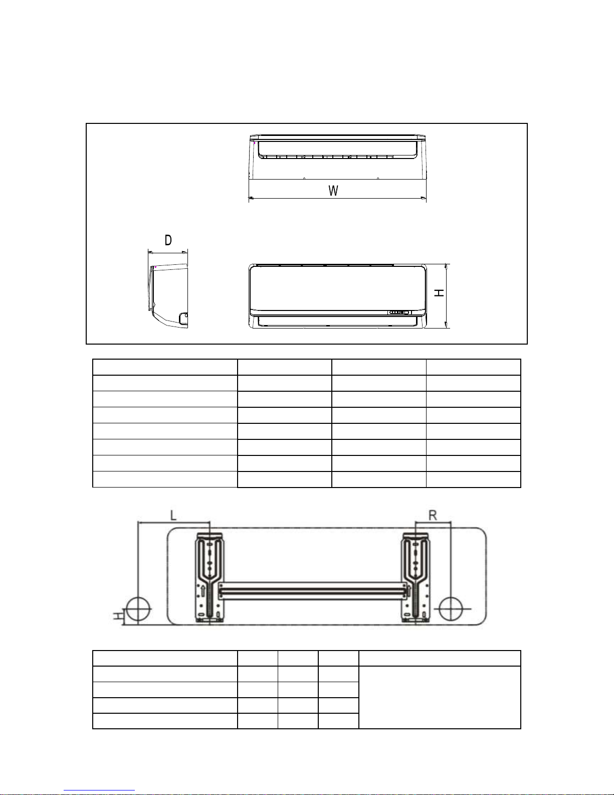
3. Dimension
3.1 Indoor Unit
Model
L(mm)
R(mm)
H(mm)
Dimension of installation hole(mm)
MS11MU-09HRFN1-QRD0W
180
110
45
¢65
MS11M-09HRFN1-QRD1W(A)
140
110
45
MS11MU-12HRFN1-QRD0W
140
110
45
MS11MU-12HRFN1-QRD0W(B)
140
110
45
Model
W D H
MS11MU-09HRFN1-QRD0W
750
198
280
MS11M-09HRFN1-QRD1W(A)
835
198
280
MS11MU-12HRFN1-QRD0W
835
198
280
MS11MU-12HRFN1-QRD0W(B)
835
198
280
MS11M-12HRFN1-QRD1W(A)
990
218
315
MS11MU-18HRFN1-QRC8GW
990
218
315
MS11M1-24HRDN1-QRC8W
1186
258
340
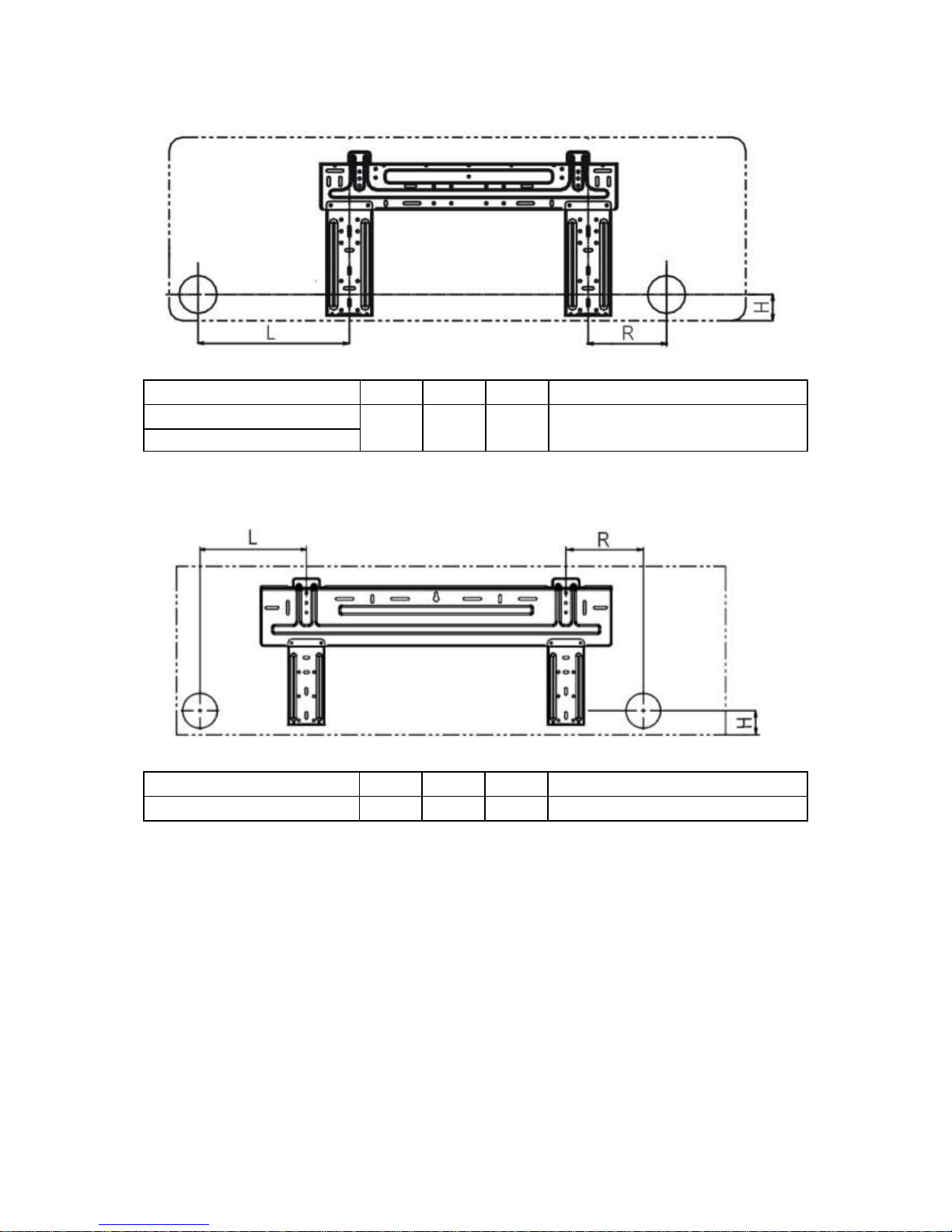
9
Model
L(mm)
R(mm)
H(mm)
Dimension of installation hole(mm)
MS11M-12HRFN1-QRD1W(A)
260
135
45
¢65
MS11MU-18HRFN1-QRC8GW
Model
L(mm)
R(mm)
H(mm)
Dimension of installation hole(mm)
MS11M1-24HRDN1-QRC8W
275
275
45
¢65
10
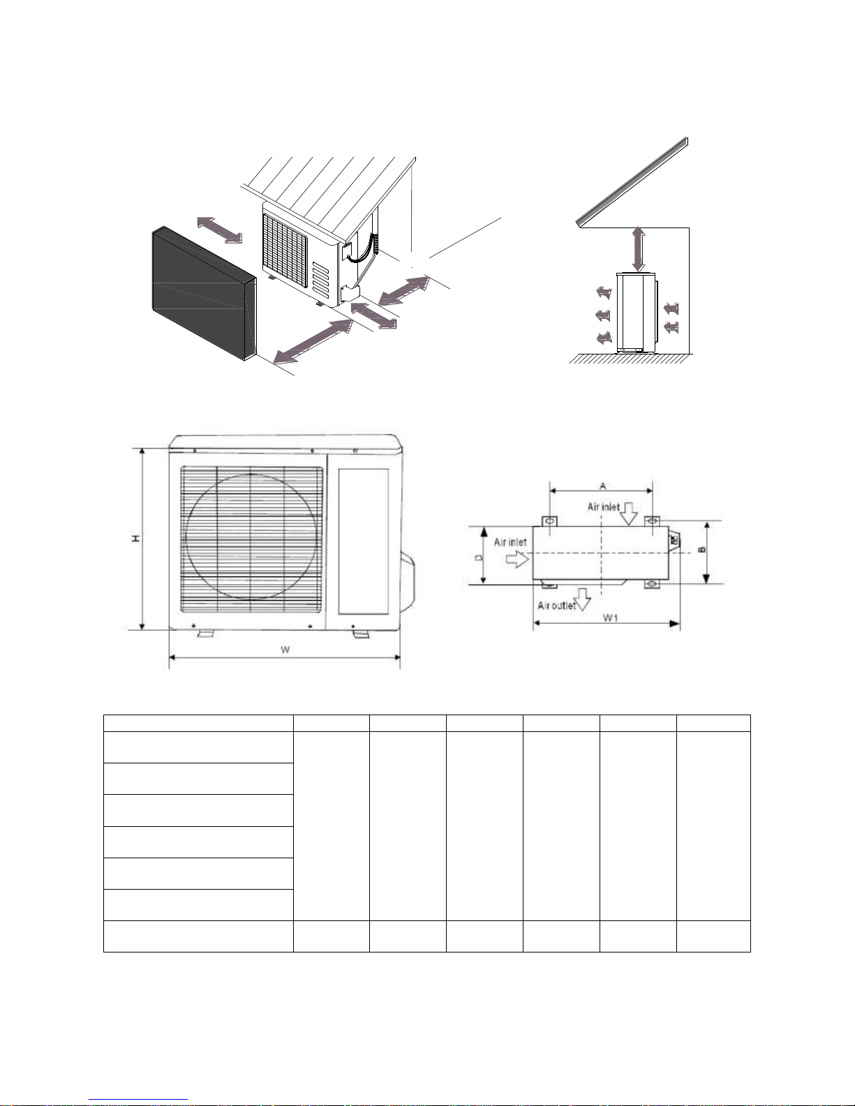
3.2 Outdoor Unit
More than 30cm
More than 60cm
More than 70cm
More than 30cm
More than 60cm
(Service space)
Fence or
obstacles
Model
W D H
W1 A B
MOC-09HFN1-QRD0W
760
285
590
823
530
290
MOC-09HFN1-QRD1W
MOC-12HFN1-QRD0W
MOC-12HFN1-QRD1W
MOC1-12HFN1-QRD0W
MOC-18HFN1-QRC8W
MOF-24HFN1-QRC8W
845
320
700
908
560
335
11
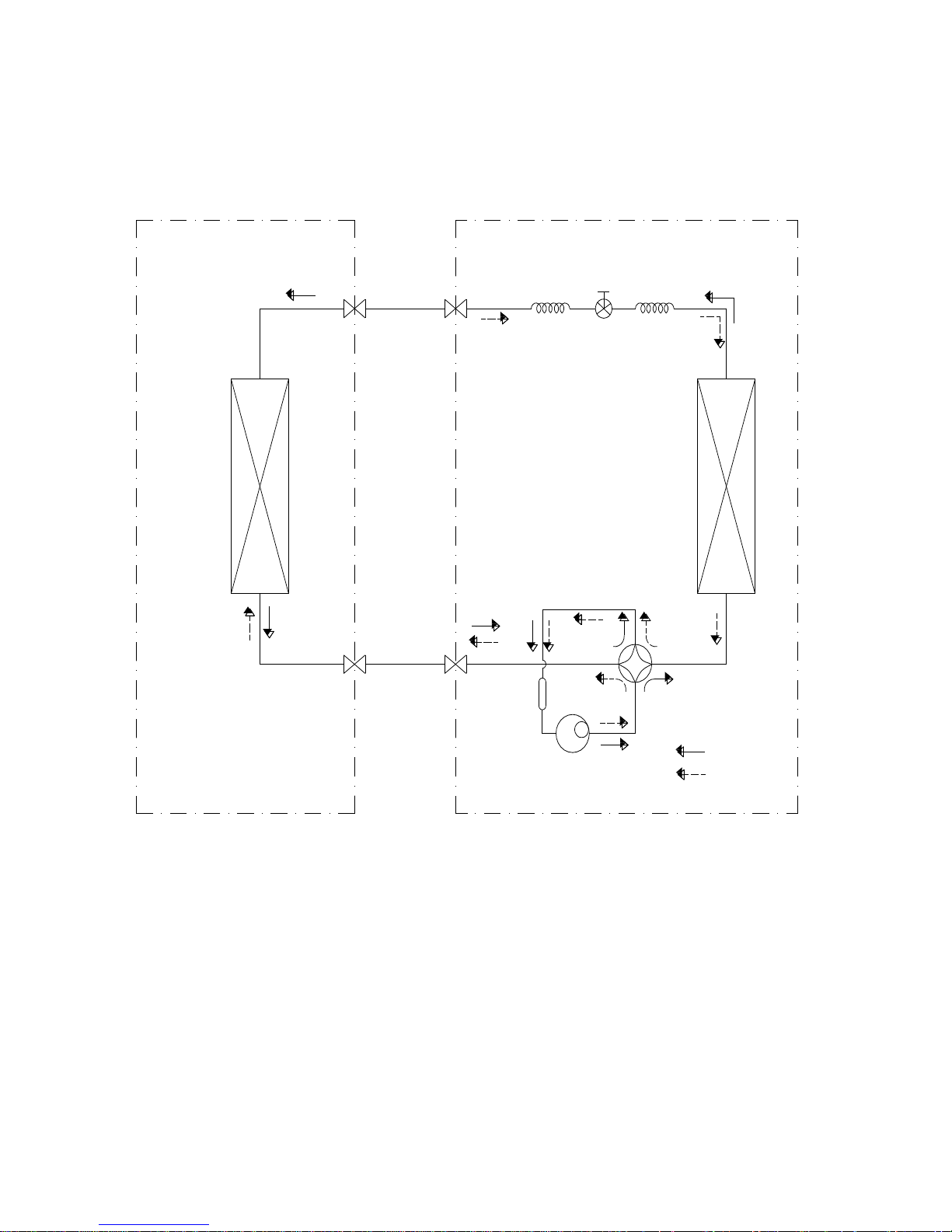
4. Refrigerant Cycle Diagram
For 9k,12k,18k models:
INDOOR OUTDOOR
LIQUID SIDE
GAS SIDE
HEAT
EXCHANGE
(EVAPORATOR)
HEAT
EXCHANGE
(CONDENSER)
COMPRESSOR
2-WAY VALVE
3-WAY VALVE
Electronic Expansion Valve
CAPILIARY TUBE
REVERSING VALVE
COOLING
HEATING
ACCUMULATOR
12
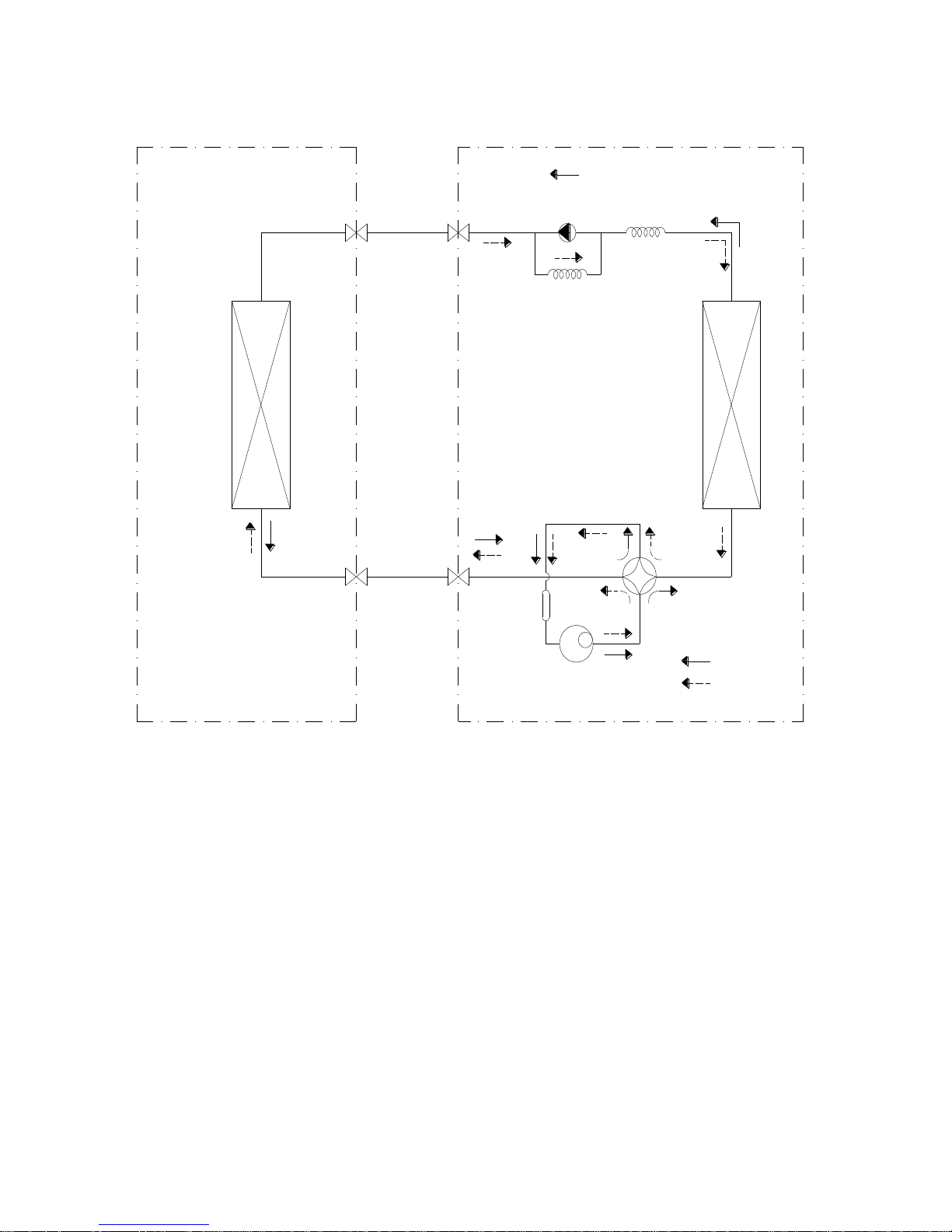
For 24k model:
INDOOR OUTDOOR
LIQUID SIDE
GAS SIDE
HEAT
EXCHANGE
(EVAPORATOR)
HEAT
EXCHANGE
(CONDENSER)
COMPRESSOR
2-WAY VALVE
3-WAY VALVE
CHECK VALVE
(Heating Model only)
CAPILIARY TUBE
REVERSING VALVE
(Heating Model only)
COOLING
HEATING
ACCUMULATOR
13
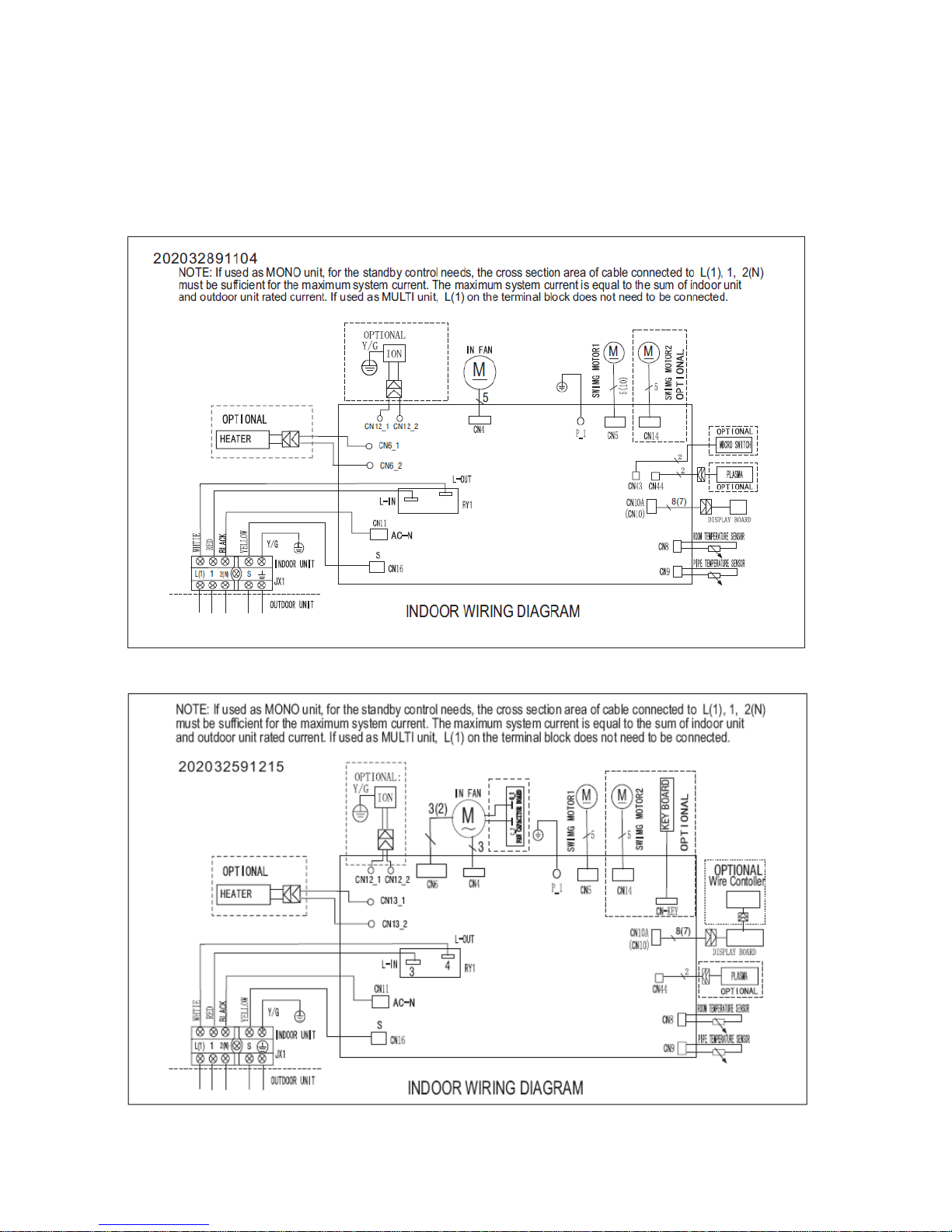
5. Wiring Diagram
5.1 Indoor Unit
MS11MU-09HRFN1-QRD0W,MS11M-09HRFN1-QRD1W(A),MS11MU-12HRFN1-QRD0W,
MS11M-12HRFN1-QRD1W(A), MS11MU-12HRFN1-QRD0W(B), MS11MU-18HRFN1-QRC8GW
MS11M1-24HRDN1-QRC8W
14
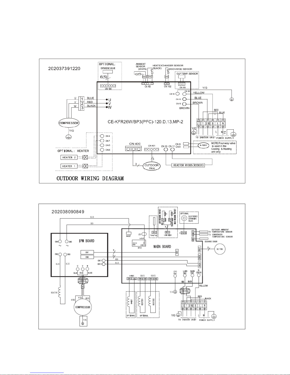
5.2 Outdoor Unit
MOC-09HFN1-QRD0W, MOC-09HFN1-QRD1W, MOC-12HFN1-QRD0W, MOC-12HFN1-QRD1W,
MOC1-12HFN1-QRD0W, MOC-18HFN1-QRC8W
MOF-24HFN1-QRC8W
15
6 Installation Details
6.1 Wrench torque sheet for installation
Outside diameter
Torque
Additional tightening torque
mm
inch
N.cm
N.cm
Ф6.35
1/4
1500(153kgf.cm)
1600(163kgf.cm)
Ф9.52
3/8
2500(255kgf.cm)
2600(265kgf.cm)
Ф12.7
1/2
3500(357kgf.cm)
3600(367kgf.cm)
Ф15.9
5/8
4500(459kgf.cm)
4700(479kgf.cm)
Ф19
3/4
6500(663kgf.cm)
6700(683kgf.cm)
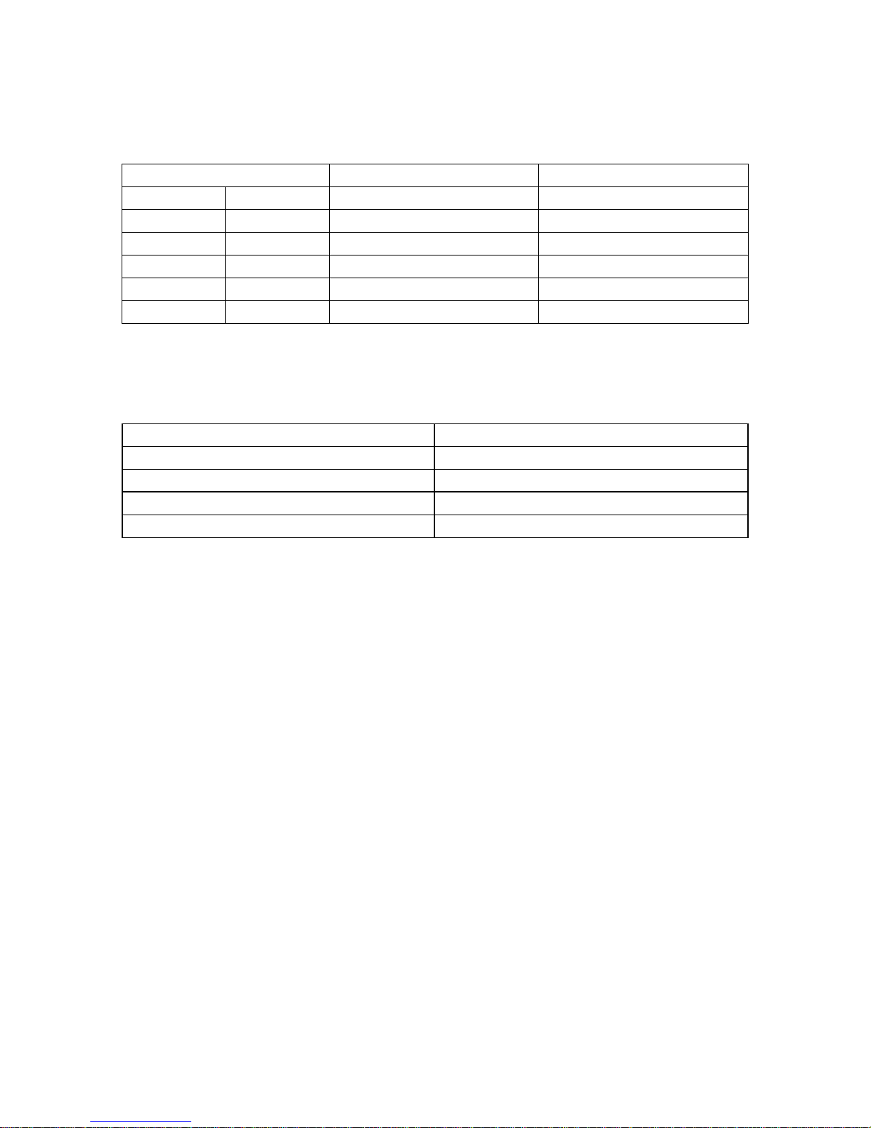
6.2 Connecting the cables
The power cord of connect should be selected according to the following specifications sheet.
Rated current of appliance
Nominal cross-sectional area (mm²)
>3 and ≤6
0.75
>6 and ≤10
1
>10 and ≤16
1.5
>16 and ≤25
2.5
The cable size and the current of the fuse or switch are determined by the maximum current indicated
on the nameplate which located on the side panel of the unit. Please refer to the nameplate before
selecting the cable, fuse and switch.
16
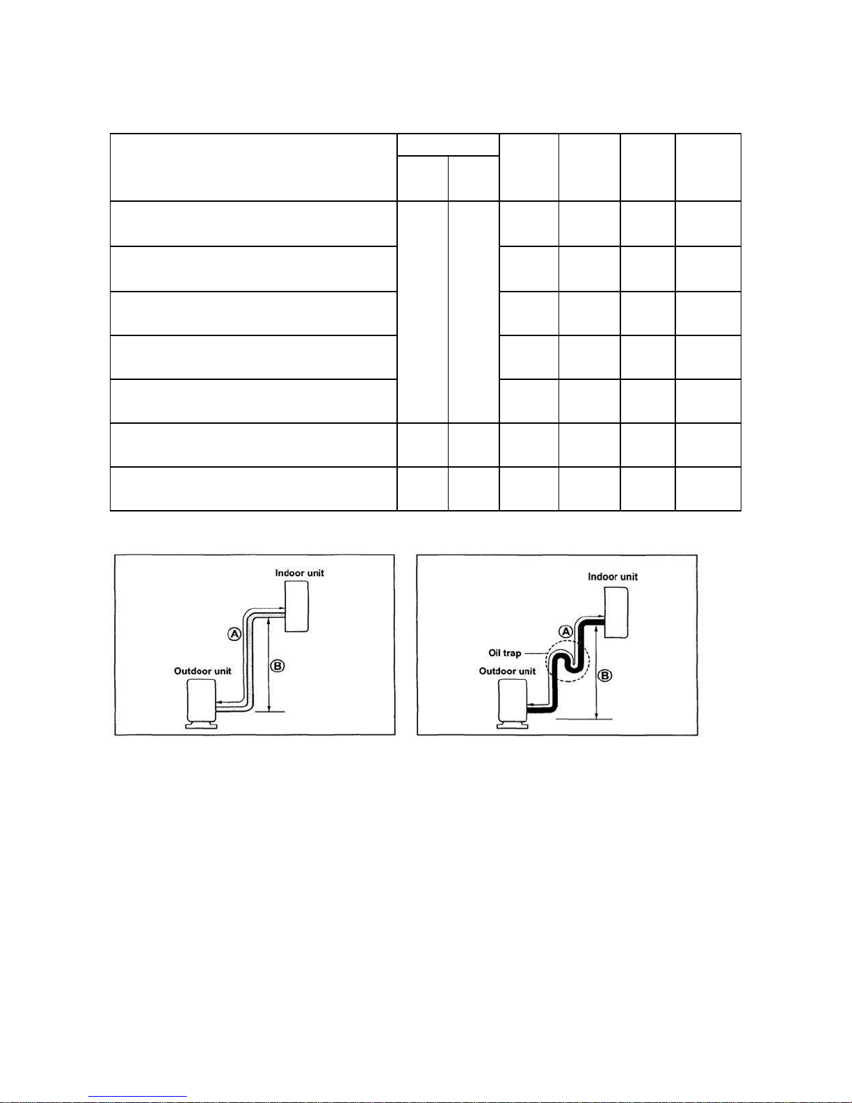
6.3 Pipe length and the elevation
The pipe length and refrigerant amount:
Model
Pipe size
Standard
length
(m)
Max.
Elevation
B (m)
Max.
Length
A (m)
Additional
refrigerant
(g/m)
Gas
Liquid
MS11MU-09HRFN1-QRD0W+ MOC-09HFN1-QRD0W
3/8’’
(Ф9.52)
1/4’’
(Ф6.35)
5 8 20
20
MS11M-09HRFN1-QRD1W(A)+ MOC-09HFN1-QRD1W
5 8 20
20
MS11MU-12HRFN1-QRD0W+ MOC-12HFN1-QRD0W
5 8 20
20
MS11M-12HRFN1-QRD1W(A)+ MOC-12HFN1-QRD1W
5 8 20
20
MS11MU-12HRFN1-QRD0W(B)+ MOC1-12HFN1-QRD0W
5 8 20
20
MS11MU-18HRFN1-QRC8GW+MOC-18HFN1-QRC8W
1/2’’
(Ф12.7)
1/4’’
(Ф6.35)
5
10
25
20
MS11M1-24HRDN1-QRC8W+MOF-24HFN1-QRC8W
5/8’’
(Ф15.9)
3/8’’
(Ф9.52)
5
10
25
40
Caution:
The capacity test is based on the standard length and the maximum permissive length is based on the
system reliability.
The oil trap should be installed per 5-7 meters.
17
6.4 Installation for the first time
Air and moisture in the refrigerant system have undesirable effects as below:
● Pressure in the system rises.
● Operating current rises.
● Cooling or heating efficiency drops.
● Moisture in the refrigerant circuit may freeze and block capillary tubing.
● Water may lead to corrosion of parts in the refrigerant system.
Therefore, the indoor units and the pipes between indoor and outdoor units must be leak tested
and evacuated to remove gas and moisture from the system.
Gas leak check (Soap water method):
Apply soap water or a liquid neutral detergent on the indoor unit connections or outdoor unit
connections by a soft brush to check for leakage of the connecting points of the piping. If bubbles
come out, the pipes have leakage.
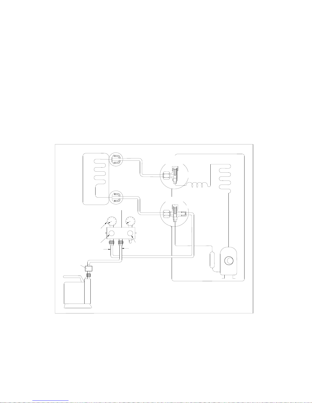
1. Air purging with vacuum pump
1) Completely tighten the flare nuts of the indoor and outdoor units, confirm that both the 2-way and
3-way valves are set to the closed position.
2) Connect the charge hose with the push pin of handle lo to the 3-way valves gas service port..
3) Connect the charge hose of handle hi connection to the vacuum pump.
4) Fully open the handle Lo of the manifold valve.
5) Operate the vacuum pump to evacuate.
6) Make evacuation for 30 minutes and check whether the compound meter indicates -0.1Mpa. If
(Indoor unit)
(Liquid side)
(Gas side)
Vacuum
pump
Vacuum
pump
Lo
Hi
Handle Hi
Two-way valve
Close
Manifold valve
Compound meter
Pressure
gauge
-0.1MPa
Handle Lo
Charge hose
Charge hose
(Outdoor unit)
Close
Three-way valve
18
the meter does not indicate -0.1Mpa after pumping 30 minutes, it should be pumped 20 minutes more. If
the pressure can’t achieve -0.1Mpa after pumping 50 minutes, please check if there are some leakage
points.
Fully close the handle Lo valve of the manifold valve and stop the operation of the vacuum pump.
Confirm that the gauge needle does not move (approximately 5 minutes after turning off the vacuum
pump).
7) Turn the flare nut of the 3-way valves about 45° counterclockwise for 6 or 7seconds after the gas
coming out, then tighten the flare nut again. Make sure the pressure display in the pressure indicator is
a little higher than the atmosphere pressure. Then remove the charge hose from the 3 way valve.
8) Fully open the 2 way valve and 3 way valve and securely tighten the cap of the 3 way valve.
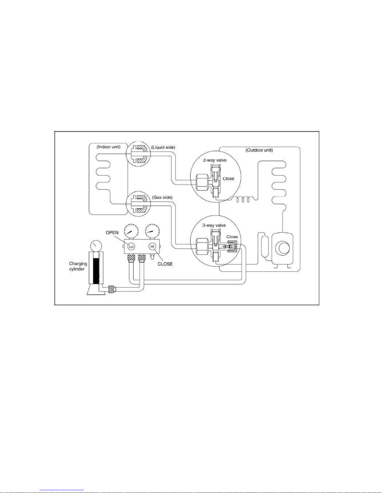
2. Air purging by refrigerant
Procedure:
1). Confirm that both the 2-way and 3-way valves are set to the closed position.
2). Connect the charge set and a charging cylinder to the service port of the 3-way valve.
3). Air purging.
Open the valves on the charging cylinder and the charge set. Purge the air by loosening the flare nut on
the 2-way valve approximately 45’ for 3 seconds then closing it for 1 minute; repeat 3 times.
After purging the air, use a torque wrench to tighten the flare nut on the 2-way valve.
4). Check the gas leakage.
Check the flare connections for gas leakage.
5). Discharge the refrigerant.
 Loading...