

Page 1
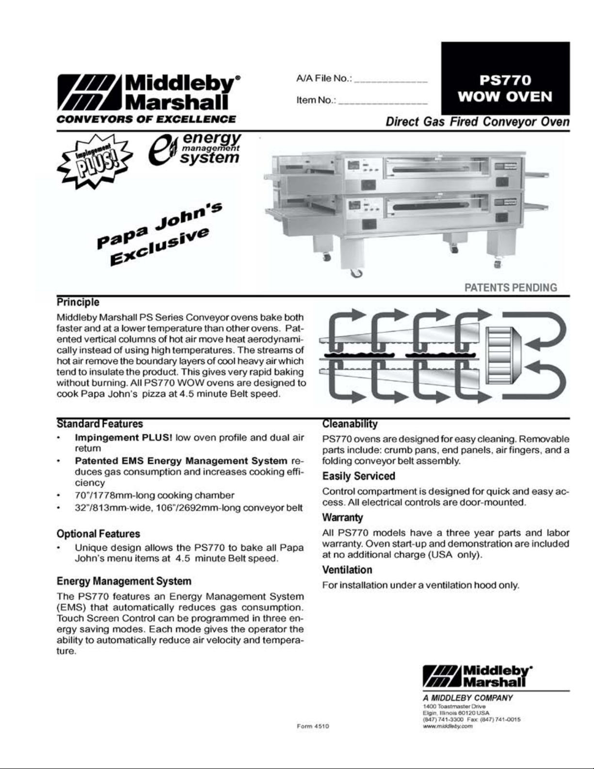
PS770 “WOW” SERIES GAS FIRED:
SPL030907-PF-BD
March 9, 2007
A MIDDLEBY COMPANY
Parts Manual
with Wiring Diagrams
for domestic ovens
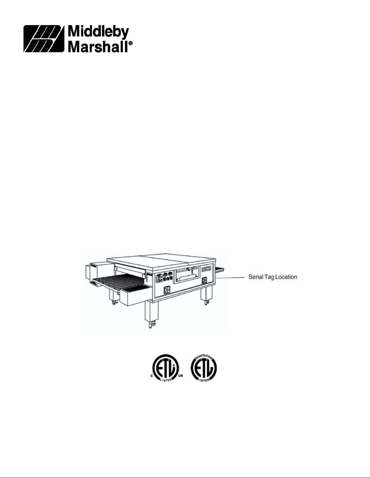
Serial # Code (Nine Digit Code)
(for units produced prior to mid-July, 2006)
First 4 digits - order of production
Fifth digit - model specific
Sixth and Seventh digit - month of production
Eighth and Ninth digit - year of production
Serial # Code (Ten Digit Code)
(for units produced after to mid-July, 2006)
First 5 digits - order of production
Sixth digit - model specific
Seventh and Eighth digit- month of production
Ninth and Tenth digit - year of production
Replaces SPL053106-PF-BD
May 31, 2006
SPL120205-PF-BD
December 2, 2005
Starting Serial # 943650206
Table of Contents: Page 2
email: techsupport@middleby.com
1-847-741-3300 fax 1-847-741- 4406
© 2006 Middleby Marshall Inc.
www.middleby.com
1400 Toastmaster Drive
Elgin, IL 60120
Page 2

Table of Contents
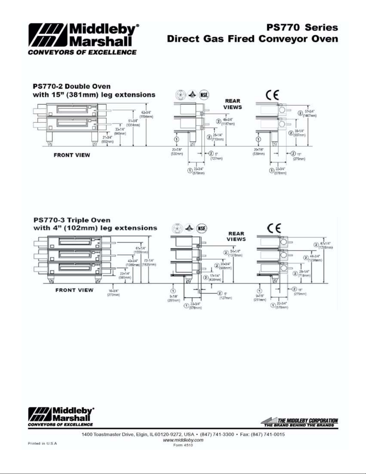
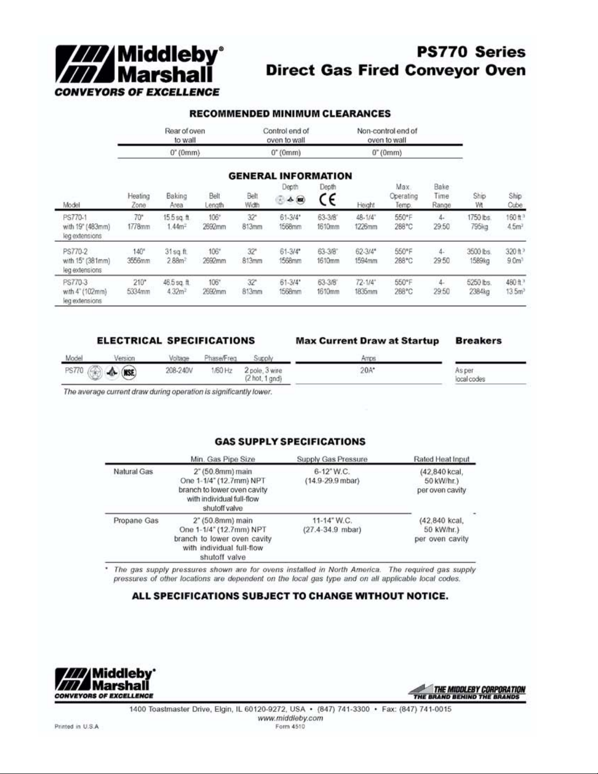
Spec Sheet ...................................................................................................................... 3
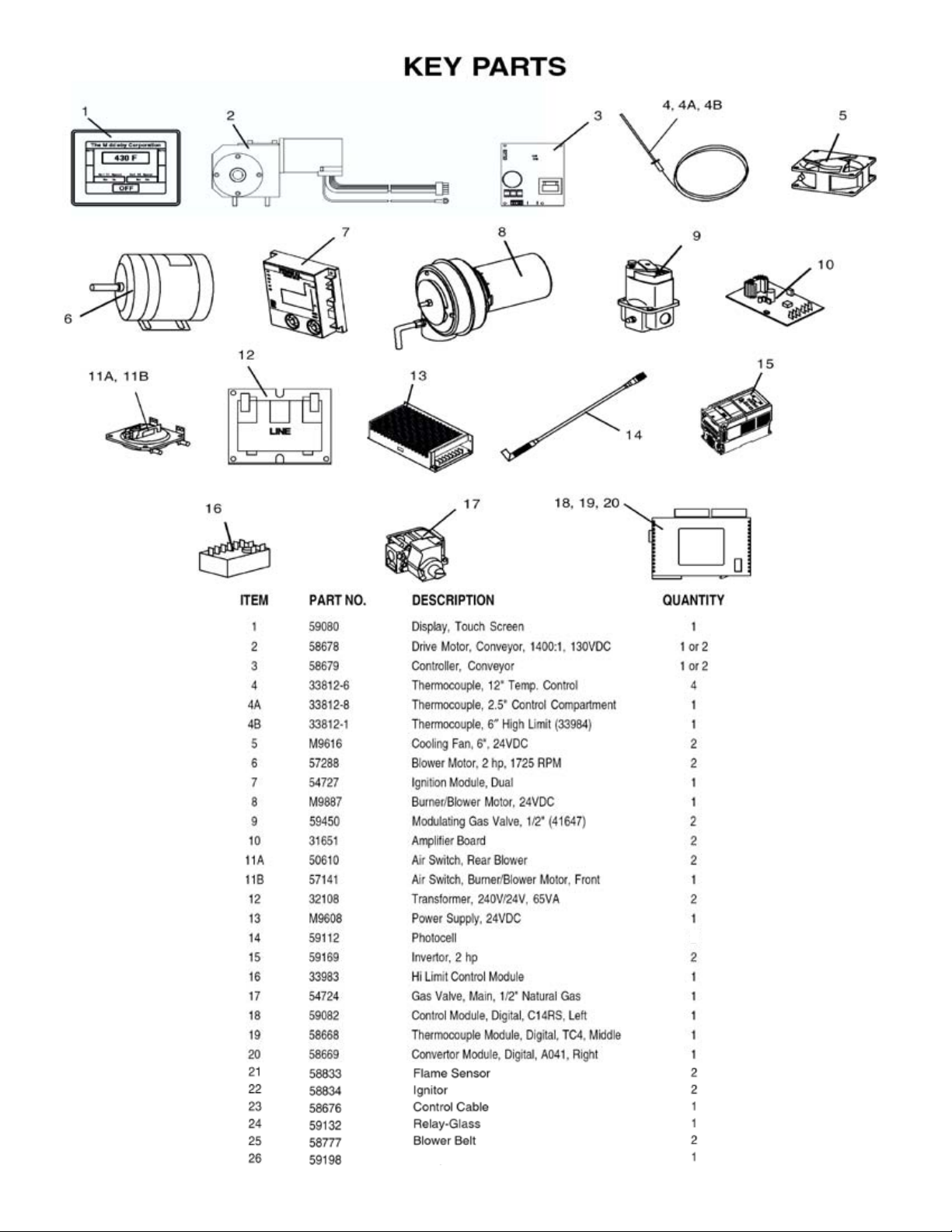
Key Parts ........................................................................................................................ 6
Cross Reference of Wiring Diagram Symbols and Part Number(s) .............................. 7
View of Installation Kit(s) and Base Kit(s) ....................................................................8
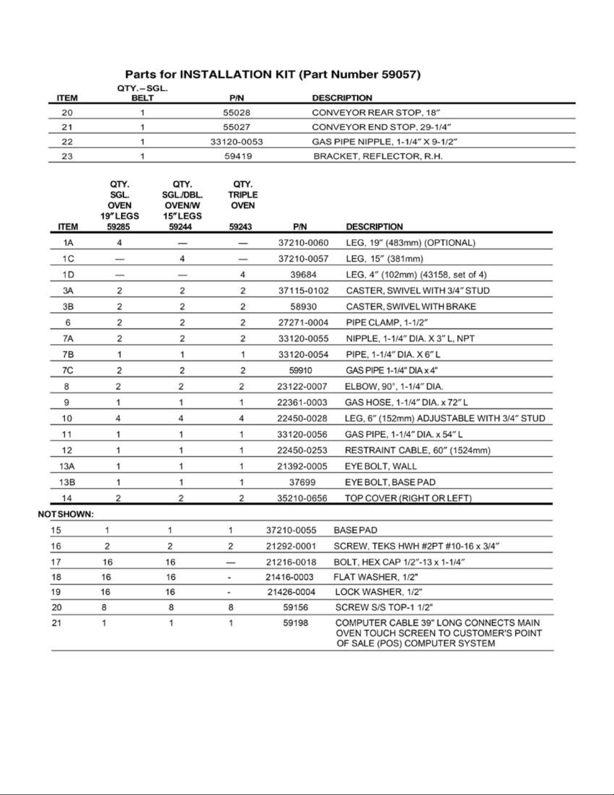
Parts for Installation Kit(s) and Base Kit(s) ................................................................... 9
View of Oven Panels, End Plugs and Window ............................................................. 10
Parts for Oven Panels, End Plugs and Window ............................................................ 11
View of Gas Piping ....................................................................................................... 12
Parts for Gas Piping ...................................................................................................... 13
View(s) of Burner/Blower Motor Assembly ................................................................. 14
Parts for Burner/Blower Motor Assembly .................................................................... 15
View(s) of Front Control Area(s) .................................................................................. 16
Parts for Front Control Area(s) ..................................................................................... 17
View of Rear Compartment and Blowers (Conveyor Drive End Shown) .................... 18
Parts for Rear Compartment and Blowers (Conveyor Drive End Shown) ................... 19
View of “Single” Belt Conveyor ................................................................................... 20
Parts for “Single” Belt Conveyor .................................................................................. 21
View of “Split” Belt Conveyor .....................................................................................22
Parts for “Split” Belt Conveyor .................................................................................... 23
Standard Finger Conguration 58762E and Part Numbers .......................................... 24
3-D View Finger Arrangement w/Part Numbers 58762-1 Rev. E .................................. 25
Thermocouple Placements 59077 Rev. G ...................................................................... 26
Wiring Diagram, G208-240, 50/60Hz, 1 Phase 54745 Rev. I ....................................... 27
Start Up Form PS770 Initial Start-Up/Check Out Procedures - Form # P/N 59279 Rev. “B” Dated 7/20/06 .. 28
234
Page 3
Page 4
Page 5
5
Page 6
-Touch Screen Display to PLC
Computer Cable Connects Main Oven Touch Screen
to Customers Point of Sale (POS) Computer System
6
1
Page 7

CROSS REFERENCE of WIRING DIAGRAM SYMBOLS and PART NUMBERS
• Air Switch 1 -Rear Right ................................................ 50610
• Air Switch 2 - Rear Left ..................................................50610
• Air Switch 3 - Front Right ...............................................57141
• Blower Motor–Left ..........................................................57288
• Blower Motor–Right ......................................................57288
• Burner Blower Motor ................................................... M9887
• Circuit Breakers
• CB1 - 15A ........................................................................45037
• CB2 - 15A ........................................................................45037
• CB3 - 15A ........................................................................45037
• CB4 - 15A ........................................................................45037
• CB5 - 3A ..........................................................................45036
• CB6 - 3A ..........................................................................45036
• CB7 - 1A ..........................................................................45644
• CB8 - 1A ..........................................................................45644
• Cooling Fan LH ............................................................. M9616
• Cooling Fan RH ............................................................. M9616
• Controller 1 DC ...............................................................58679
• Controller 1 DC (split belt) ..............................................58679
• Conveyor Motor ..............................................................58678
• Conveyor Motor (split Belt) ............................................58678
• Dual Burner .....................................................................54719
• Converter Module - Digital A041, Right .........................58669
• Control Module - Digital C14RS-A, Left ........................59082
• Thermocouple Module - Digital TC4, Middle ................58668
• Gas Valve .........................................................................54724
• Green Light (Reset Button) .............................................35145
• GT30 Display ..................................................................59080
• Ignition Module, Dual .....................................................54727
• Inverter - 1 Left, 2HP.......................................................59169
• Inverter - 2 right, 2 HP .....................................................59169
• Switch(es)
• LS1 (LH RR), Momentary .....................................28021-0061
• LS2 (RH RR), Momentary .....................................28021-0061
• LS3 (RH Front), Inter Lock ....................................28021-0047
• LS4 (LH Front), Inter Lock ....................................28021-0047
• Reset Button ....................................................................35145
• Mod Valve 1 (41647) .......................................................59450
• Mod Valve 2 (41647) .......................................................59450
• Photocell 1 Entrance ........................................................ 59112
• Photocell 2 Exit ...............................................................59112
• Power Supply ................................................................. M9608
• Relay ................................................................................59132
• Signal Amplier 1 ............................................................31651
• Signal Amplier 2 ............................................................31651
• TB1 RR LT (3 Pole) .........................................................44390
• TB2 RR LT (3 Pole) .........................................................44390
• TB3 RR RT (3 Pole) ........................................................44390
• TB4 RR LT (8 Pole) .........................................................31047
• TB5 Comp Brkt (4 Pole) ...............................................M0593
• TB6 Comp Brkt (4 Pole) ...............................................M0593
• TC1 - 6” High Limit (33984) .......................................33812-1
• TC2 - 12”, Oven Temp. ................................................33812-6
• TC3 - 12”, Oven Temp. ................................................33812-6
• TC4 - 2.5”, Control Compartment ................................33812-8
• XFMR1 - 240V/24V 65 VA .............................................32108
• XFMR2 - 240V/24V 65 VA .............................................32108
• High Limit .......................................................................33983
Wiring Diagram Drawing # 54745 Rev. I Shown on Page 27.
SET THE ENERGY MODES TO THE FOLLOWING SETTINGS AS OF 3/08/2007
OVEN
WITH POS COMPUTER CABLE OVEN WITHOUT POS CABLE
MODE 2--7:00 MINUTES MODE 2--7:00 MINUTES
MODE 3--14:00 MINUTES MODE 3--20:00 MINUTES
MODE 4--1 HOUR MODE 4--1 HOUR
(This is a “CONTROLLED” Screen-Password Required)
7
Page 8
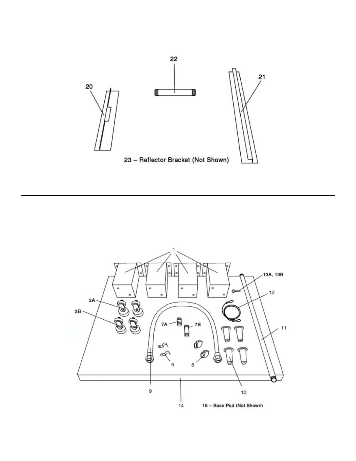
VIEW OF INSTALLATION KIT (PART NUMBER 59057)
VIEW OF BASE PAD KIT
8910
Page 9
Page 10

47
48 FILTER-ONLY
46
EARLIER MODELS REQUIRED A RIGHT TO LEFT KIT TO CONVERT TO RIGHT TO LEFT OPERATION PART #59340
NOT SHOWN ITEM 45
Page 11

111213
Page 12

Page 13

Page 14

(1/8” GAP)
14
Page 15

15
Page 16

26
1, 1A, 9
1, 1A, 9
View of FRONT CONTROL AREA(S)
162717
Page 17

Page 18

18
NOTE: IDENTIFY THE DEFECTIVE INNER FROM THE DEFECTIVE OUTER BEARING ITEM 14 PER ENGINEERING’S REQUEST
(THESE PARTS ARE TO BE RETURNED FOR OUR INSPECTION)
Page 19

19
Page 20

View of Single-Belt Conveyor
20
Page 21

212223
Page 22

Page 23

Page 24

B
C
D
E
1/9/2006
2/15/2006
9/19/2006
2/23/2007
CHG’D DESC FROM 770M TO 770G ECN006363A
CHANGED DESC FROM PS670M TO PS770M ECN006034
RELEASE TO PROD RPM WAS 2000, Hz WAS 60 ECN 004386
AJ
AJ
AJ
AJ
CHANGED BAKE TEMP WAS 480-490 F ECN 006285
E
E
SYMMETRICAL FINGER CONFIG.
AVG CONTROL T/CS: 4 USED
ENT: TOP INNER & OUTER LOCATIONS: 12” PROBES
EXIT: TOP INNER & OUTER LOCATIONS: 12” PROBES
RPM=2100RPM, INVERTERS SET @ 63Hz AND ENERGY SAVING LOW SPEED 40
BAKE TIME & TEMP: 4’30” @ 480-490°F
BOTH SIDES END PLUGS HAVE DIVERTERS
OVEN DERATED TO 175,000 BTU/HR
24
°
Page 25

Right to Left or Left to Right - No Change to Finger Configuration
RPM: 2100 (Inverters Set @ 63Hz)
25
Page 26

THERMOCOUPLE PLACEMENTS 59077 REV G
G_ T/C Positions Shown for Either Conveyor Direction
G
26
Page 27

27
Page 28

OVEN WITH POS CABLE
MODE 2--7:00 MINUTES
MODE 3--14:00 MINUTES
MODE 4--1 HOUR
OVEN WITHOUT POS CABLE
MODE 2--7:00 MINUTES
MODE 3--20:00 MINUTES
MODE 4--1 HOUR
NOTE: ATTACH This PS770 Initial Start-Up/Check Out Procedures Completely Filled Out Along With
The Completely Filled Out Startup Checklist Pages 1 And 2 (Form #P/N 37201 • Rev. F • V1• 7/05)
28
P/N 59279
REV. “B”
7/20/06
Page 29

 Loading...