

Page 1
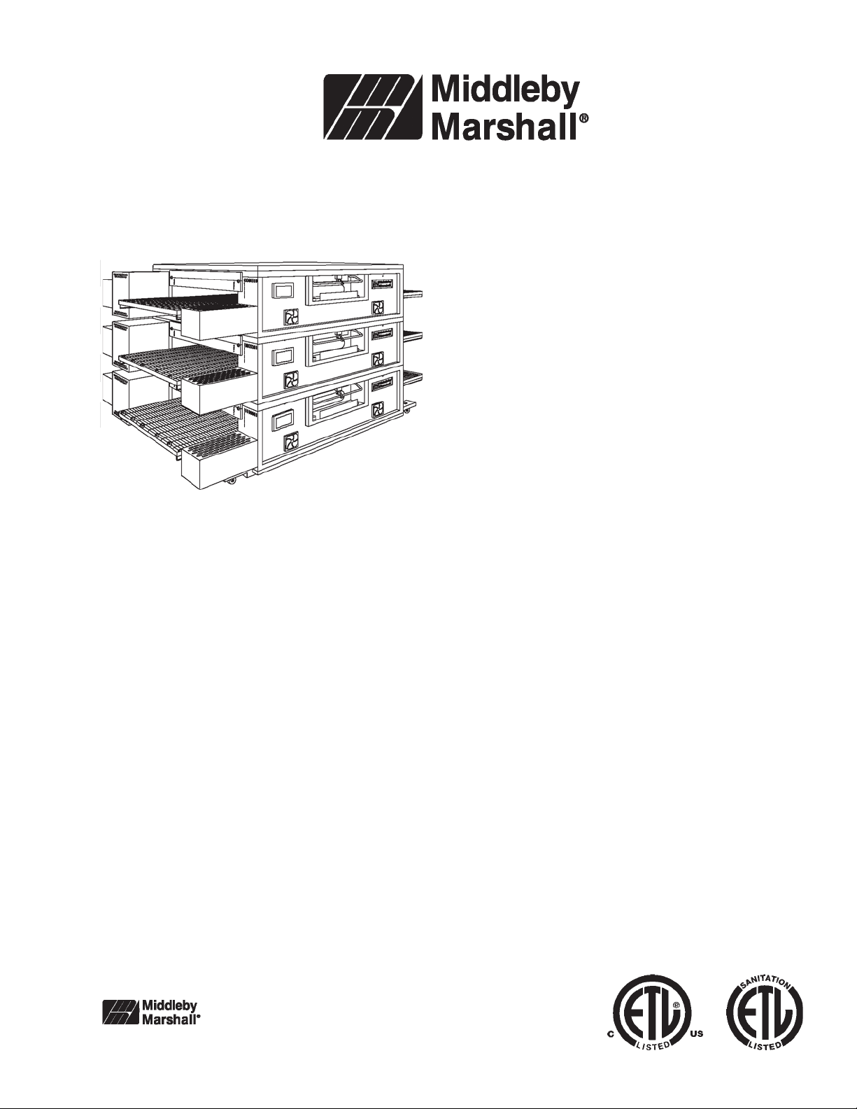
PS670 Series
Gas
Domestic & Std. Export
ENGLISH
P/N 58814
January 18, 2006
PS670 Series Gas Ovens
Model:
• PS670G Gas
Combinations:
• Single Oven
• Double Oven (Two-Stack)
• Triple Oven (Three-Stack)
OWNER'S OPERATING AND
INST ALLATION MANUAL
for domestic and standard export ovens
©2006 Middleby Marshall Inc.
is a registered trademark of Middleby Marshall, Inc. All rights reserved.
Middleby Cooking Systems Group • 1400 Toastmaster Drive • Elgin, IL 60120 • (847)741-3300 • FAX (847)741-4406
Page 2
2
Page 3

Table of Contents
Page
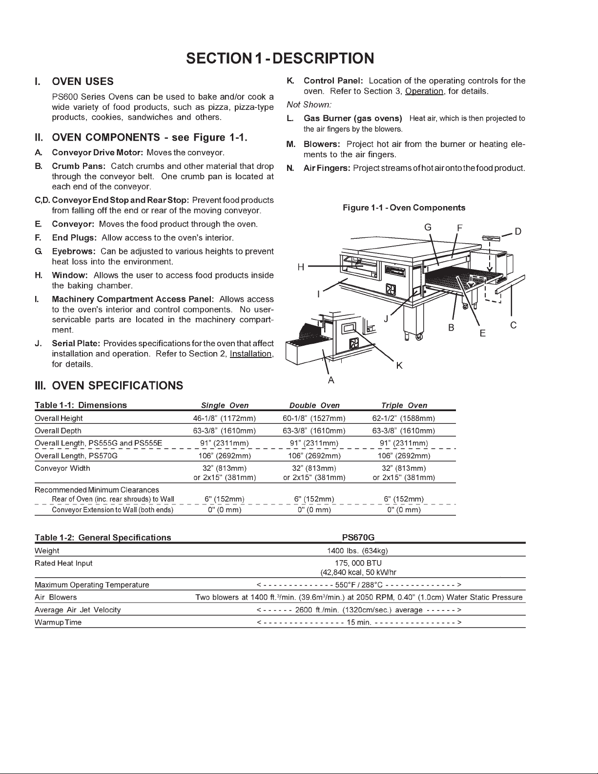
SECTION 1
DESCRIPTION .................................................................... 4
I. OVEN USES .................................................................... 4
II. OVEN COMPONENTS .................................................... 4
A. Conveyor Motor Drive .............................................. 4
B. Crumb Pans ............................................................... 4
C. Conveyor End Stop ................................................... 4
D. Conveyor Rear Stop ................................................. 4
E. Conveyor .................................................................... 4
F. End Plugs .................................................................... 4
G. yebrows ...................................................................... 4
H. Window ....................................................................... 4
I. Machinery Compartment Access Panel ................... 4
J. Serial Plate ................................................................. 4
K. Control Panel ............................................................. 4
L. Gas Burner ................................................................. 4
M. Blowers ...................................................................... 4
N. Air Fingers ................................................................. 4
III. OVEN SPECIFICATIONS ................................................. 4
A. Dimensions ................................................................ 4
B. General Specifications ............................................. 4
C. Electrical Specifications for PS670G Gas Ovens ... 5
D. Gas Orifice and Pressure Specifications
for PS670G Gas Ovens ........................................... 5
SECTION 2
INSTALLATION .................................................................. 5
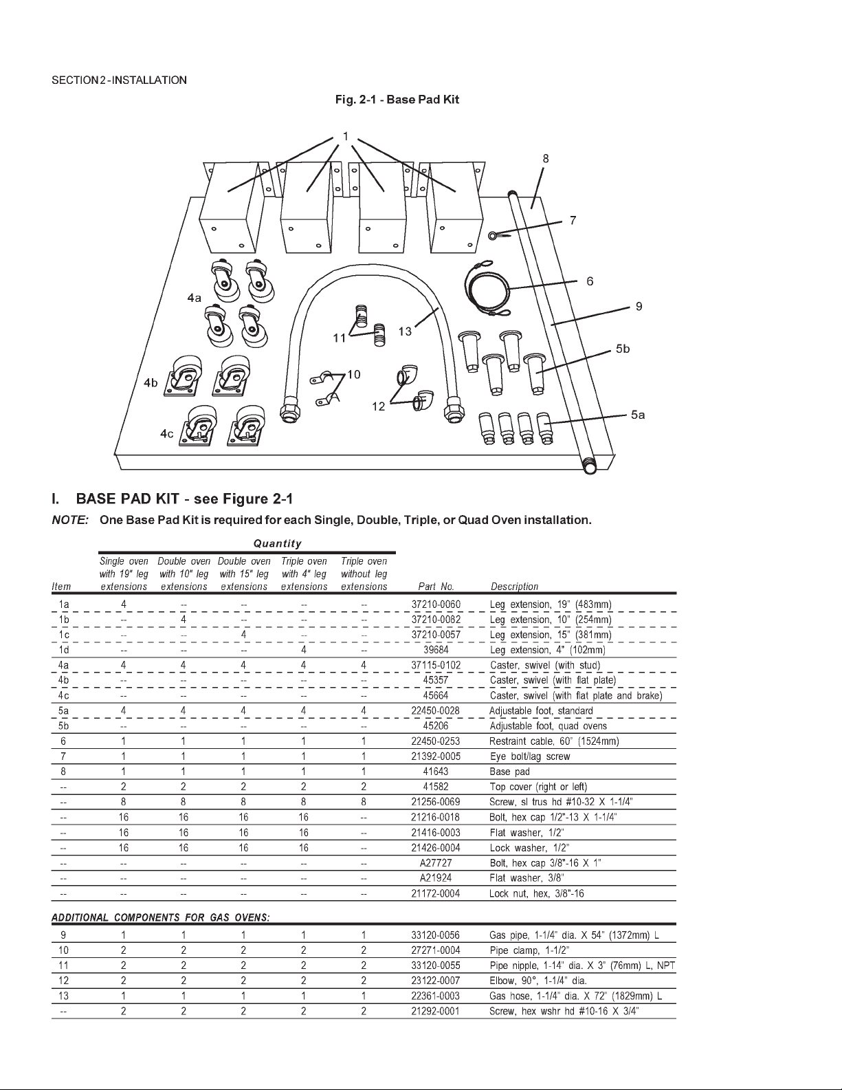
I. BASE PAD KIT ............................................................... 6
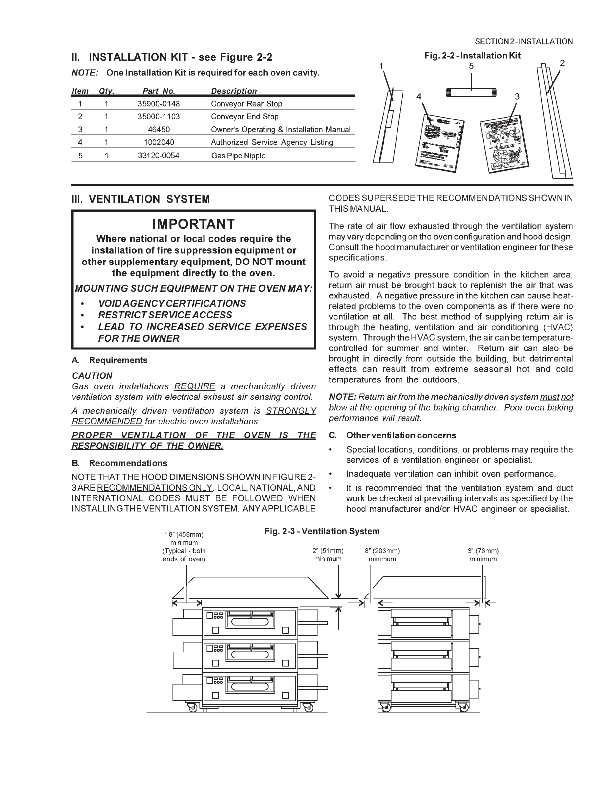
II. INSTALLATION KIT ........................................................ 7
III.VENTILATION SYSTEM ................................................. 7
A. Requirements ............................................................ 7
B. Recommendations .................................................... 7
C. Other Ventilation Concerns ...................................... 7
Page
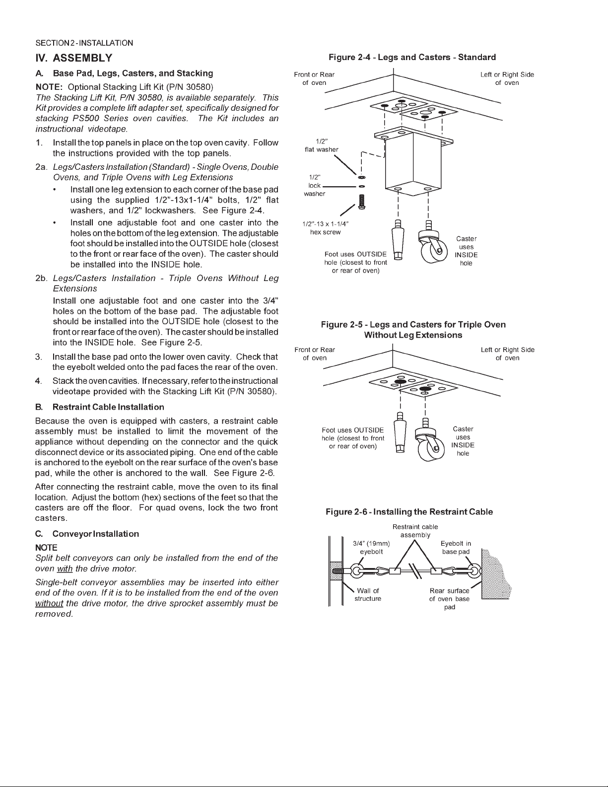
IV. ASSEMBLY ...................................................................... 8
A. Base Pad, Legs, Casters, and Stacking .................. 8
B. Restraint Cable Installation ...................................... 8
C. Conveyor Installation ................................................ 8
D. Conveyor Installation ................................................ 8
V. FINAL ASSEMBLY ....................................................... 10
VI. ELECTRICAL SUPPLY ............................................... 10
A. Additional Information - Gas Ovens ....................... 10
B. Connection ............................................................... 1 0
VII. GAS SUPPLY ............................................................. 11
A. Gas Utility Rough-In Recommendations ............... 11
B. Connection ............................................................... 1 2
C. Gas Conversion ....................................................... 12
SECTION 3
OPERATION ........................................................................ 13
I. LOCATION AND DESCRIPTION OF CONTROLS ....... 13
II. NORMAL OPERATION, STEP-BY-STEP ..................... 14
A. Daily Startup Procedure ......................................... 14
B. Daily Shutdown Procedure ..................................... 14
III. QUICK REFERENCE: DIGITAL TEMPERATURE
CONTROLLER ........................................................... 14
IV. QUICK REFERENCE: TROUBLESHOOTING ............ 1 5
SECTION 4
MAINTENANCE .................................................................. 16
I. MAINTENANCE - DAILY .............................................. 16
II. MAINTENANCE - MONTHLY ....................................... 17
III. MAINTENANCE - EVERY 3 MONTHS ........................ 18
IV. MAINTENANCE - EVERY 6 MONTHS ....................... 1 9
V. KEY SPARE PARTS KIT ............................................. 20
SECTION 5
ELECTRICAL WIRING DIAGRAMS ................................... 2 1
I. WIRING DIAGRAM, 670 GAS OVEN, 208/240V,
50/60 Hz, 1 Ph ............................................................... 39
3
Page 4
456789101112
Page 5
Page 6
Page 7
Page 8
Page 9

Page 10

Page 11

Page 12

Page 13

Increase Decrease
A. Main On/Off Button
SECTION 3 - OPERATION
C. Temperature Control Display
E. Message Bar
D. TEMP Set
Left
LOCATION AND DESCRIPTION OF CONTROLS
A. Main On/Off Button
Turns all oven functions on or off. If the oven is below the set
point, it will rise to the set point and turn the conveyor on.
If it is turned off and the oven is above 200° F, the blowers
will remain on until the oven drops below 200° F.
B. Conveyor Time Setting
Adjusts and displays the conveyor bake time. Dual belt
ovens have two displays, single units have one.
B. Conveyor Time Setting
Right
C. Temperature Control/Display
Displays the set point of both right and left sides of the
oven.
D. TEMP Set
Pressing on the “TEMP” button shows individual displays
and combined adjustments.
E. Message Bar
Indicates various messages pertaining to current oven
conditions.
13
Page 14

NORMAL OPERATION - STEP-BY-STEP-
A. Main Screen
1. When the unit has been “OFF” for more than 1 minute
the controller will display the screen saver, as shown
in Figure 3-1. To start operation, push the “Enter/
Reset” button. The controller will display the “OFF”
screen, as shown in Figure 3-2.
Figure 3-1 Screen Saver
2. Push the “ON/OFF” button to start the oven. The
controller will display the screen, as shown in
Figure 3-3.
ON/OFF button
Figure 3-3 Main Screen ON
3. To change the temperature, push the “TEMP” button.
The controller will display the screen, shown in
Figure 3-4. To change the left temperature, push the
←←
“
←” arrow button. Then push either the “↑” arrow or “↓”
←←
arrow buttons to increase or decrease temperatures
respectively. To change the right temperature, push
the “→” arrow button. Then push either the “↑” arrow or
“↓” arrow buttons to increase or decrease temperatures accordingly. When the proper temperatures are
entered, push the “Enter/Reset” button. The controller
will now show the display shown in Figure 3-3.
Figure 3-2 Main Screen OFF
TEMP Set button
Figure 3-4 Temperature Screen
14
Page 15

4. To change the conveyor belt speed, push the “TIME”
button. The controller will display the screen, shown in
Figure 3-5. To change the minute setting, push the “
←←
←”
←←
arrow button. Then push either the “↑” arrow or “↓” arrow
buttons to increase or decrease the time accordingly.
To change the second setting, push the “→” arrow
button. Then push either the “↑” arrow or “↓” arrow
buttons to increase or decrease the time accordingly.
When the proper times are entered, push the “ENTER/
RESET” button. The controller will now show the
display shown in Figure 3-3.
Message Bar
ON/OFF button
Energy Level Indicators
TEMP button
TIME button
Figure 3-5 Belt Speed Screen
B. Daily Startup Procedure
1. Check that the circuit breaker/fused disconnect is in
the On position. Check that the window is closed. The
touch panel display should be lit.
2. Adjust the conveyor to the desired bake time.
3. Press the temperature button to display right and left
hand oven settings. Set temperatures as desired.
4. Press the “ON” button to activate the oven. The
conveyor will not run, until the oven temperature has
reached the set points.
C. Daily Shutdown Procedure
1. Make certain there are no products left on the conveyor
in the oven.
2. Press the “ON/OFF” button to turn the oven off.
3. Open the window to allow the oven to cool faster.
4. After the oven has cooled and the blowers have turned off,
the circuit breaker/fused disconnect may be turned off.
Quick Reference – Touch Screen Controller
A. Main Screen
1. ON/OFF button - Used to turn oven On and Off.
2. TIME - See Separate Instructions.
3. TEMP - See Separate Instructions.
4. Energy level indicators - Indicators to either side of the
screen indicate the energy input to that side of the
oven.
5. Message bar - Indicates various messages pertaining
to current oven conditions.
B. Oven Temperature/Set Point/Indicator Screen
1. Right actual temperature - Indicates current average
temperature of the right side of the oven.
2. Left actual temperature - Indicates current average
temperature of the left side of the oven.
3. Set point temperature - Pressing on this value allows
the user to adjust the set point of the oven.
4. Exit - Returns to the main screen.
C. Energy Modes
Energy Mode One - This mode is automatic, and starts
(bake time +1 minute) after the last product has entered
the oven. In this mode, the main oven blowers will lower to
1500 RPM, while the oven maintains temperature and belt
speed.
15
Page 16

III. QUICK REFERENCE: TROUBLESHOOTING
SYMPTOM PROBLEM SOLUTION
Oven will not
turn On.
Oven will not
heat.
Oven is operating, but
little or no air is coming
from the fingers.
Conveyor will not move.
No electrical power • Check that the circuit breaker/fused disconnect is on. Make
sure the emergenct stop button is on.
No gas pressure
Burner did not light
Air fingers may be assembled incorrectly after
cleaning.
Oven is not up to operating
temperature.
Conveyor may be jammed.
• Make sure main gas is on.
• Turn oven off, and restart. If it still does not light, call for
service.
• Turn oven off, and allow to cool. Reassemble fingers
correctly.
• Allow oven to preheat.
• Turn oven off, and allow to cool. Check conveyor for blockage.
IV. SCREEN ALERTS
SYMPTOM PROBLEM SOLUTION
lower right hand corner
The internal battery needs
to be replaced to retain
energy mode timings.
• A qualified service technician should accomplish this.Battery Symbol in the
High Control Compart-
ment Temperature
Combustion Blower
problem.
Control Over Temp Front filters are clogged • Clean or replace filters.
Front belt jammed Front belt has stopped • Remove obstruction, and restart oven.
Rear Belt jammed Rear belt has stopped • Remove obstruction, and restart oven.
High Temp Error Thermocouple or • Call service
Belt off-Oven not Normal operation until
in temperature Oven reaches operating
Energy Saving Mode 1 Normal operation
Energy saving mode 2 Normal Operation
Clean and replace the
front fan filters.
The computer has
detected a problem with
either the main, or burner
blowers.
PLC malfunction
temperature
• Failure to do this will eventually shut down the oven due to
excessive temperature.
• This should be corrected by a qualified service technician.Main Blower problem or
• If no obstruction, call service.
• If no obstruction, call service.
Energy saving Mode 3 Normal operation
16
Page 17

1718192021
Page 18

Page 19

Page 20

Page 21

ITEM QTY. P/N DESCRIPTION
1 1 59083 DIGITAL DISPLAY
2 1 58678 MOTOR, CONVEYOR DRIVE
3 2 58679 CONVEYOR CONTROL BOARD
4 1 58276 INVERTER
5 1 M9608 POWER SUPPLY
6 1 33984 KIT, THERMOCOUPLE
7 1 M9616 FAN, COOLING
8 1 57288 MOTOR, BLOWER
9 1 57141 AIR SWITCH
10 1 54727 KIT, IGNITION MODULE
11 1 M9887 ASSEMBLY, BURNER BLOWER/MOTOR
12 1 41647 VALVE, MODULATING GAS, 1/2"
13 1 31651 AMPLIFIER, MODULATING VALVE
14 1 33983 HIGH LIMIT CONTROL MODULE, 240V
15 1 32108 TRANSFORMER, 240Vp:24Vs
16 1 60088 PLC MODULE
17 1 58668 THERMOCOUPLE MODULE
18 1 58669 CURRENT MODULE
19 1 58363 PHOTOCELL
12 345
10
15
16, 17, 18
19
Page 22

Wiring Diagrams (electrical schematics)
54745B
22
G208-240 volt 50/60 Hz, 1 Phase
Page 23

NOTES
23
Page 24

 Loading...