

Page 1

Electric
PN
April 2013
Series Electric Oven
E
Page 2

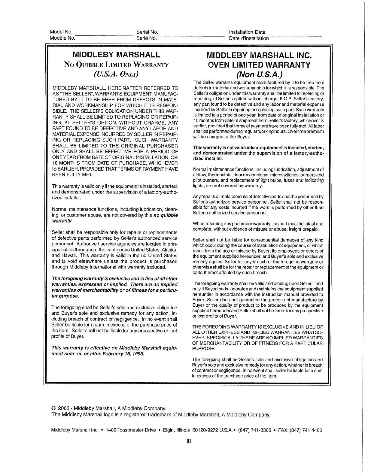
NOTICE:
This Owner’s Operating and Installation Manual should be given to the user. The operator of the oven
should be familiar with the operation of the oven.
This manual must be kept in a prominent, easily reachable location near the oven.
It is suggested to obtain a service contract with a Middleby Marshall Authorized Service Agent.
WARNING
FOR YOUR SAFETY, DO NOT STORE OR USE GASOLINE OR OTHER FLAMMABLE VAPORS AND LIQUIDS IN THE
VICINITY OF THIS OR ANY OTHER APPLIANCE.
WARNING
Improper installation, adjustment, alteration service or maintenance can cause property damage, injury or
death. Read the installation, operation and maintenance instructions thoroughly before installing or
servicing this equipment.
IMPORTANT
An electrical wiring diagram for the oven is located inside the machinery compartment of the oven.
IMPORTANT
It is the customer’s responsibility to report any concealed or non-concealed damage to the freight company.
Retain all shipping materials until it is certain that the equipment has not suffered concealed shipping damage.
NOTICE
CONTACT YOUR MIDDLEBY MARSHALL AUTHORIZED SERVICE AGENT TO INSTALL AND PERFORM
MAINTENANCE AND REPAIRS. AN AUTHORIZED SERVICE AGENT DIRECTORY IS SUPPLIED WITH YOUR OVEN.
NOTICE
Using any parts other than genuine Middleby Marshall factory manufactured parts relieves the manufacturer
of all warranty and liability.
NOTICE
Middleby Marshall (Manufacturer) reserves the right to change specifications at any time.
NOTICE
The equipment warranty is NOT VALID unless the oven is installed, started and demonstrated under the
supervision of a factory certified installer.
NOTICE
THIS EQUIPMENT IS FOR PROFESSIONAL USE AND SHALL BE USED BY QUALIFIED PERSONNEL.
RETAIN THIS MANUAL FOR FUTURE REFERENCE.
ii
Page 3
Page 4
Page 5
Page 6

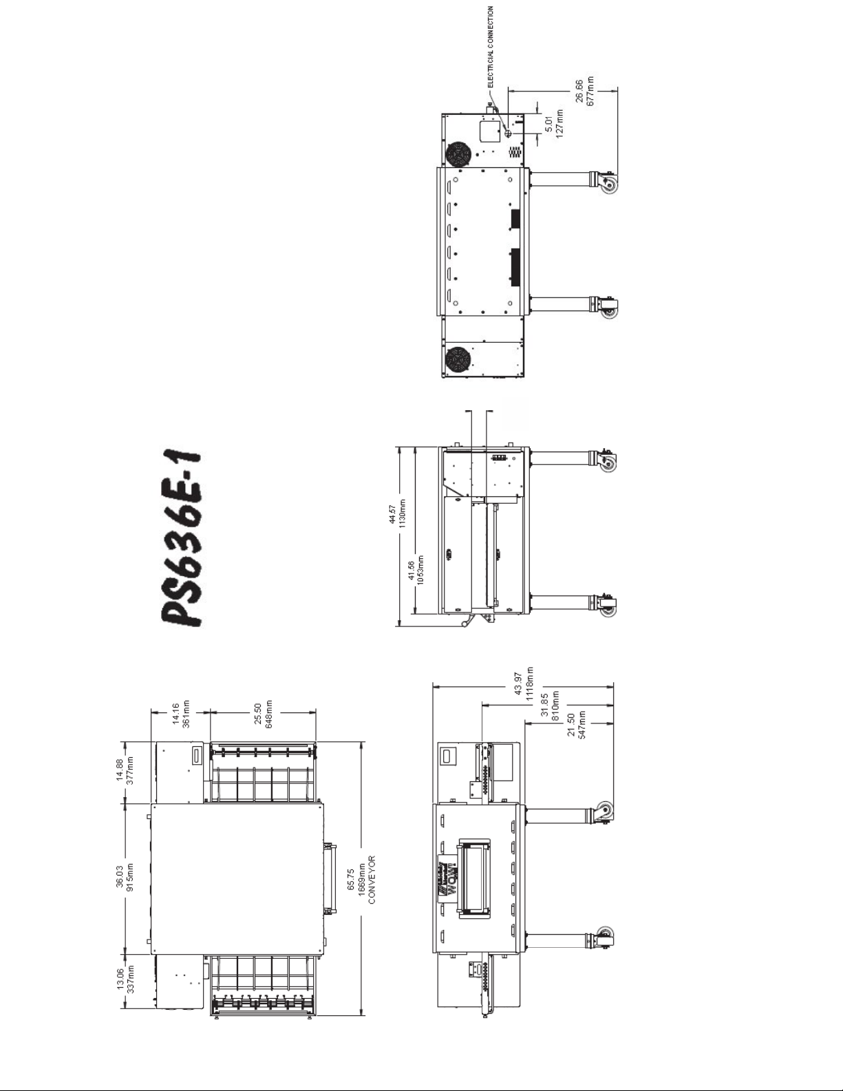
I. PS636E OVEN SPECIFICATIONS
Table 1 -1 Dimensions Single Oven Double Oven Triple Oven
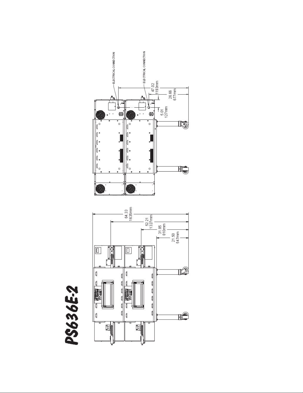
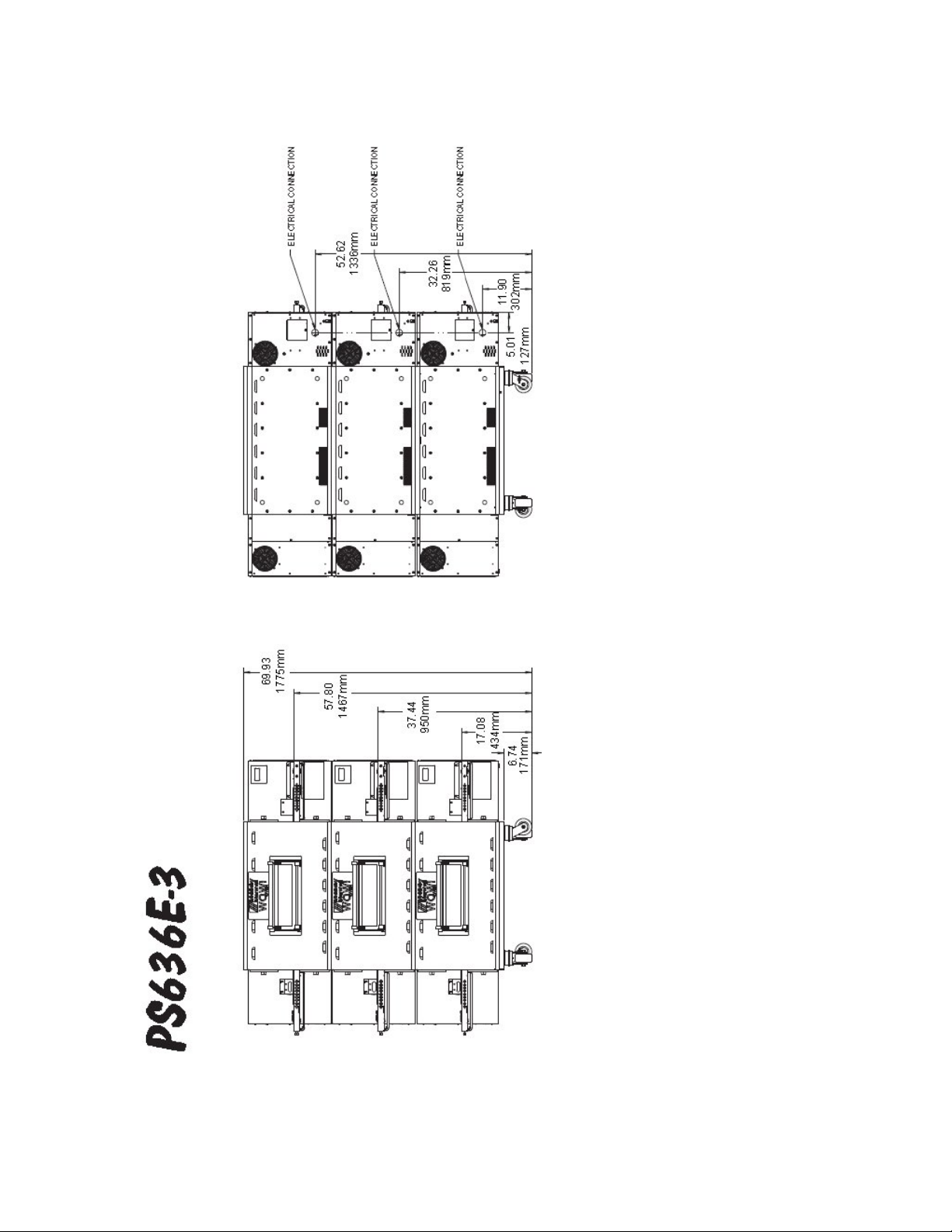
Overall Height 44” (1118 mm) 64-3/8” (1635 mm) 69-3/4” (1772 mm)
Overall Depth 44-1/2” (1130 mm) 44-1/2” (1130 mm) 44-1/2” (1130 mm)
Overall Length (w/o exit trays) 65-3/4” (1670 mm) 65-3/4” (1670 mm) 65-3/4” (1670 mm)
Conveyor Width (belt is 24”)
25-1/2” (648 mm) or,
2 x 11” (279 mm)
25-1/2” (648 mm) or,
2 x 11” (279 mm)
25-1/2” (648 mm) or,
2 x 11” (279 mm)
Baking Area 6.0 sq. ft. (.557m2)
Recommended Minimum Clearances
Rear of Oven to Wall 0” (0 mm) 0” (0 mm) 0” (0 mm)
Control end of conveyor to wall 2” (50.8 mm) 2” (50.8 mm) 2” (50.8 mm)
Non-control end of conveyor to wall 2” (50.8 mm) 2” (50.8 mm) 2” (50.8 mm)
Table 1-2 General Specifications PS636E Electric Oven
Weight of Single Oven 734 lbs. (333 kg)
Max Operating Power 19.8 kW
Operating Temperature Range 350-600ºF (177 - 316ºC)
Warm-up Time 25 minutes
Belt Speed (Time)
0:30 – 20:00 (STD)
0:30 – 15:00 (SPECIAL)
Table 1-3 Electrical Specifications for PS636E electric ovens
DOMESTIC OVENS
VOLTAGE PHASE HZ kW BREAKER WIRING
208 3 50-60 19.8 70 4-WIRE / L1,L2,L3 & GROUND
240 3 50-60 19.8 60 4-WIRE / L1,L2,L3 & GROUND
INTERNATIONAL OVENS
VOLTAGE PHASE HZ kW BREAKER WIRING
208 3 50-60 19.8 70 4-WIRE / L1,L2,L3 & GROUND
240 3 50-60 19.8 60 4-WIRE / L1,L2,L3 & GROUND
380 3 50-60 19.8 40 5-WIRE / L1,L2,L3,N & GROUND
400-416 3 50-60 18.3 - 19.8 5-WIRE / L1,L2,L3,N & GROUND
230 3 50-60 18.2 5-WIRE / L1,L2,L3,N & GROUND
(400 WYE)
30
30
NOTE
Wiring Diagrams are contained in Section 5 of this manual
and are also located inside the right hand oven control box.
Additional electrical information is provided on the oven’s serial plate.
This manual must be kept for future reference.
2
Page 7
3.57
91mm
OPENING
PS636E SINGLE OVEN
3
Page 8
PS636E DOUBLE OVEN
4
Page 9
PS636E TRIPLE OVEN
5
Page 10

SECTION 2
SECTION 2
INSTALLATION
INSTALLATION
WARNING
The oven must be installed on an even (level) non-flammable flooring and any adjacent walls must
be non-flammable. Recommended minimum clearances are specified in the Description section of
this Manual.
WARNING
Do not obstruct the flow of combustion and ventilation air to and from your oven. There must be no
obstructions around or underneath the oven. Constructional changes to the area where the oven is
installed shall not affect the air supply to the oven.
CAUTION
For additional installation information, contact your local Authorized Service Agent.
NOTE
There must be adequate clearance between the oven and combustible construction. Clearance
must also be provided for servicing and for proper operation.
NOTE
An electrical wiring diagram for the oven is located inside the machinery compartment.
NOTE
All aspects of the oven installation, including placement, utility connections, and ventilation requirements,
must conform with any applicable local, national, or international codes. These codes supersede the
requirements and guidelines provided in this manual.
NOTE
In the USA, the oven installation must conform with local codes. Installed ovens must be electrically
grounded in accordance with local codes, or in the absence of local codes,
with the National Electrical Code (NEC), or ANSI/NFPA70.
NOTE - CANADA INSTALLATION
In Canada, the oven installation must conform with local codes. Installed ovens must be electrically
grounded in accordance with local codes, or in the absence of local codes, with the Canadian Electrical Code
CSA C22.2.
NOTE - AUSTRALIA INSTALLATION
In Australia, the oven installation must conform with any requirements of the appropriate statutory authority.
NOTE - CE OVEN INSTALLATION
Four casters are provided to allow the oven to be more easily moved to the installation location. These casters
are intended to simplify pre-installation movement only, and are NOT suitable for use as part of a CE oven
installation. During the installation procedure, the casters MUST be removed, so that the oven can be
supported by the supplied 152mm adjustable legs.
NOTE - GROUNDING INSTRUCTIONS
The oven must be grounded. In the event of an electrical short circuit, grounding reduces the risk of electric
shock by providing an escape wirdor electric current. This product is equiped with a cord having a grounding wire
and an appropriate grounding plug. This plug must be plugged into a properly installed outlet in accordance with all
local codes and ordinances.
WARNING: Improper installation of the grounding plug can result in the risk of electric shock. The grounding wire
has insulation with an outer surface that is green with or without yellow stripes.
Implementation of the grounding requirements should be carried out by a qualified electrician or service techni-
cian. Do not modify the appliance plug provided. If the appliance plug does not fit the outlet, the outlet should be
replaced by a qualified electrician.
6
Page 11

SECTION 2
INSTALLATION
NOTE: The oven, when installed, must be electrically
grounded in accordance with local codes, or in the absence of local codes, with the National Electrical Code
(NEC), or ANSI/NFPA70.
NOTE
There must be adequate clearance between
the oven and any adjacent combustible construction. Clearance must also be provided
for servicing and for operation.
CAUTION
It is recommended that the oven be placed under
a ventilation hood for adequate air supply and
ventilation.
CAUTION
Do not obstruct the flow of ventilation air to and
from your oven. Do not obstruct the fan holes in
the rear of the unit.
I. UNLOADING
Your Middleby Marshall PS636-Series Oven is shipped
partially assembled. It will arrive in a carton on a crate.
The crate and carton
Bill of Lading. Report any visible damage to the transport
company, and check for the proper number of crates. If
apparent damage is found, make arrangements to file a
claim against the carrier. Surface Interstate Commerce
Regulations (U.S.A.) require that the claim must be
initiated by the consignee within 10 days from the date that
the shipment is received.
Installer should be qualified to install commercial
conveyor ovens, having suitable lifting equipment to
prevent personal injury.
must be examined before signing the
7
Page 12
66955
OPTION
66956
67280
ELECTRIC OVEN
2
3
2
3
8
Page 13
Page 14

Page 15

Page 16

Page 17

Page 18

Electric Oven
Page 19

UTILITY ROUGH-IN DIMENSIONS AND POSITIONING
FOR PS636-SERIES OVENS
SECTION 2
INSTALLATION
WARNING
DO NOT USE CONDUIT FOR
GROUND CONNECTION.
CAUTION
IT IS RECOMMENDED THAT THE OVEN
BE PLACED UNDER A VENTILATION
HOOD FOR ADEQUATE AIR SUPPLY
AND VENTILATION.
ELECTRIC SUPPLY TO BE
PROVIDED BY CUSTOMER
CIRCUIT BREAKER
A seperate circuit breaker with lockout/tagout electrical
shutoff is required for each, seperately wired oven.
See breaker sizing requirements below:
ELECTRICAL SPECIFICATIONS
NOTE: Please refer to page 2, Electrical Specifications
chart and your units data plate information, for more
detailed information.
DOMESTIC:
4-WIRE SYSTEM (L1,L2, L3 & GROUND)
208V, 60 Hz, 19.8 kW, 70A Service
240V, 60 Hz, 19.8 kW, 60A Service
Do
NOT
use conduit for ground.
.
/
&
&
/
4O/VEN
MM
/
.
/
&
&
4O/VEN
MM
Suggested dimensions are shown; utility code
3UGGESTEDDIMENSIONSARESHOWNUTILITYCODE
requirements supersede any factors shown.
REQUIREMENTSSUPERSEDEANYFACTORSSHOWN
Figure 2-9. Typical Oven Installation
SUPPLY WIRE
Supply wire size must be in accordance with the
National Electrical Code (current edition) and must be in
compliance with local codes.
SUGGESTED
If space permits, service should be located near the
control console end of the oven(s) to allow convenient
access to safety switches.
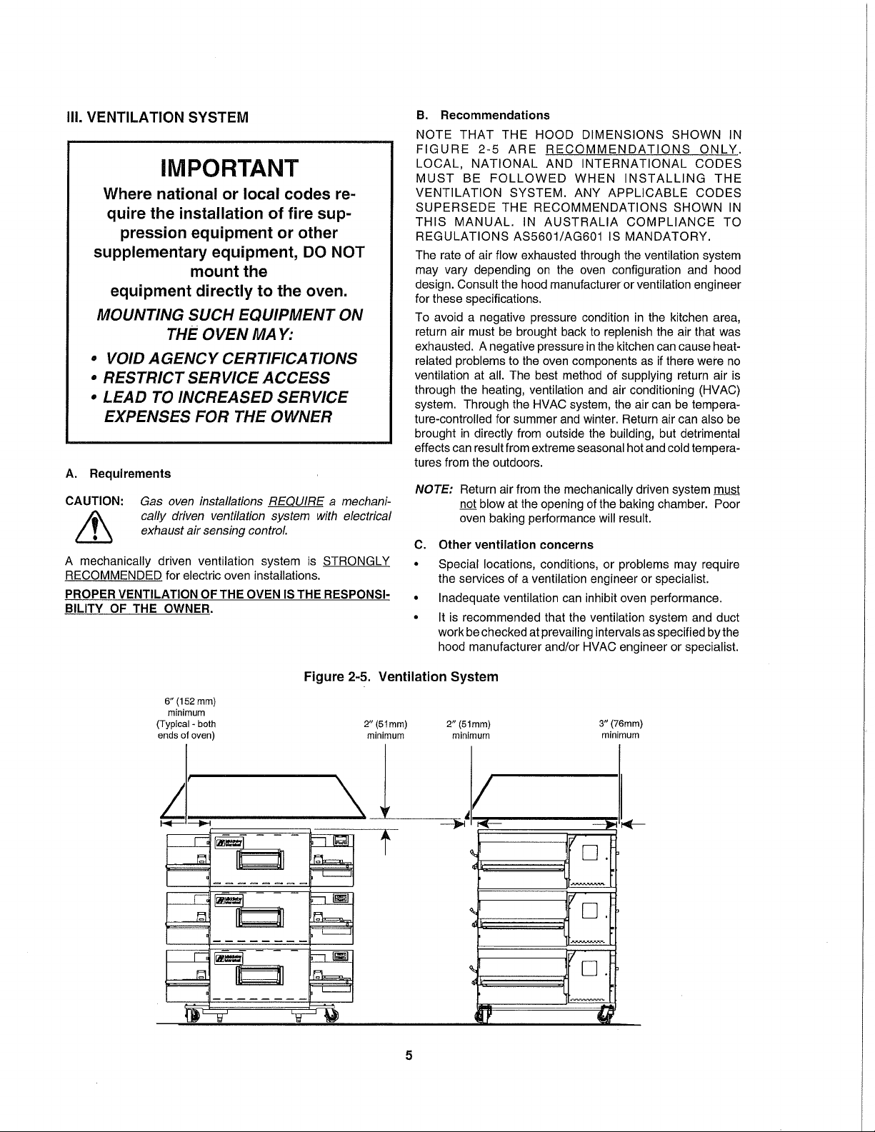
II. VENTILATION GUIDELINES
Use of a ventilation hood is not required for proper
operation, but installation must conform with all local
codes and regulations.
or
EXPORT: CE MODEL
4-WIRE SYSTEM (L1,L2, L3 & GROUND)
208V, 50/60 Hz, 19.8 kW, 30A Service
230-240V, 50/60Hz, 18.2/19.8 kW, 30A Service
5-WIRE SYSTEM (L1, L2, L3, N & GROUND)
380V, 50/60 Hz, 19.8 kW, 40A Service
400-416V, 50/60 Hz, 18.3-19.8 kW, 30A Service
230V (400Y), 50/60 Hz, 18.2 kW, 30A Service
Do NOT
use conduit for ground.
POWER RATING
19.8 kW Standard
Local codes and conditions vary greatly from one area to
another and must be complied with. Following are the
suggested requirements for good ventilation. Please remember these are recommendations or guidelines, you
may have a special condition or problem that will require
the services of a ventilation engineer or specialist. Proper
ventilation is the oven owner’s responsibility. Improper
ventilation can inhibit oven performance.
11
Page 20

SECTION 2
INSTALLATION
III. ELECTRICAL CONNECTION INFORMATION
FOR PS624-SERIES OVENS.
WARNING
Authorized supplier personnel normally accomplish the connections for the ventilation
system, electric and gas supplies, as arranged by the customer. Following these
connections, the factory-authorized installer
can perform the initial startup of the oven.
Check the oven data plate (Figure 2-10) before making any
electric supply connections. Electric supply connections
must agree with data on the oven data plate.
NOTE: The electric supply installation must satisfy the
requirements of the appropriate statutory authority, such
as the National Electrical Code (NEC), ANSI/NFPA70,
(U.S.A.); the Canadian Electrical Code, CSA C22.2; the
Australian Code AG601; or other applicable regulations.
A fused disconnect switch or a main circuit breaker
(customer furnished)
supply line for each oven; it is recommended that this
switch/ circuit breaker have lockout/tagout capability. The
electric supply connection must meet all national and local
electrical code requirements. Copper is the recommended
material for the electrical supply conductors.
MUST be installed in the electric
IV. ELECTRIC SUPPLY
Electrical connection is a fixed conduit connection.
See Electrical Specifications chart on page 2.
The supply conductors must be of the size and
material (copper) recommended to provide the current required; (refer to the data plate for the ampere
specifications).
ELECTRICAL
INLET
International CE Plate
Figure 2-10. Typical Electric Oven Data Plate
Figure 2-11. Junction Connection Box
Domestic Plate
12
Page 21

Page 22

Page 23

Page 24

Page 25

Page 26

Page 27

Page 28

Page 29

Page 30

1 2 3 4 5 6a, b
ITEM
QTY
P/N
DESCRIPTION
7 8 9 10 11a, b, c 12
13 14
19a, b 20
1 1 65564 Digital Display, Programmed
2 1 65756 Motor, Conveyor Drive
3 1 65566 Conveyor Control Board
4 1 66065 Inverter, ½ HP (230V Input)
5 1 61186 Power Supply
6a
6b
7 1 36451 Fan,Cooling
8 2 62044 Air Switch
9 1 65701 Blower Motor, 3/8 HP
10 1 44549 Contactor
11a
11b
11c
12 1 50794 Relay, 30A (240V coil)
13 1 33983 Hi Limit Thermostat
14 1 45036 Circuit Breaker, 3A (Control Circuit)
15 1 65565 Board,Main – I/O
16 2 60520-2 Thermocouple, 2” Grounded
17 1 60185 Photo Sensor
18 1 59132 Relay, DPDT 24VDC Coil
19a 2 66381 Belt, Blower-to-Blower
19b 2 66382 Belt, Blower-to-motor
20 1 45644 Circuit Breaker, 1A (Conveyor Motors)
21 1 59206 Circuit Breaker, 10A (Blower Motors)
22 1 67043 Blower Bearing Assembly
23 1 45019 Circuit Breaker, 3-pole 63A
24 1 58131 RFI Filter, 50A (380V CE Only)
15 16 17 18
21
22 23 24
KEY SPARE PARTS PS636 ELECTRIC
1
1
1
1
44914
44568
68063
68064
68065
Power Relay, 208-240V
Power Relay, 380-415V
Heating Element, 208V, 19.8kW (400-415V)
Heating Element, 240V, 19.8kW
Heating Element, 380V, 19.8kW
22
Page 31

Page 32

Page 33

Page 34

Page 35

Page 36

Page 37

Page 38

Page 39

Page 40

Page 41

 Loading...