

Page 1
PS520E-Series Electric Ovens:English
Parts Manual
for domestic, CE and standard export ovens
Serial Number Code:
SPL102606-PF-BD
October 26, 2006
replaces SPL082505-PF-BD
dated August 25,2005
Models w/adjustable conveyor
belt feature are serial
051471006 and higher
Serial Tag
Location
First Four Digits - Order Of Production
Fifth Digit - Model Specific
Sixth & Seventh Digit - Month of Production
Eight & Ninth Digit - Year of Production
017070405 - Starting Serial Number and Higher
©2006 Middleby Marshall Inc.
Table Of Contents: Page III
www.middleby.com
email: techsupport@middleby.com
1400 Toastmaster Drive • Elgin, IL 60120
phone: 847-741-3300 • fax: 847-741-4406
Page 2

WARNING
FOR YOUR SAFETY, DO NOT STORE OR
USE GASOLINE OR OTHER FLAMMABLE
VAPORS AND LIQUIDS IN THE VICINITY OF
THIS OR ANY OTHER APPLIANCE.
WARNING
Improper installation, adjustment, alteration,
service, or maintenance can cause property
damage, injury, or death. Read the
installation, operating, and maintenance
instructions thoroughly before installing or
servicing this equipment.
NOTICE
The warranty is NOT VALID unless the oven is installed, started, and
demonstrated under the supervision of a factory-authorized installer
NOTICE
Contact your authorized Service Agency to perform maintenance and
repairs. A Service Agency Directory is supplied with your oven.
NOTICE
Using any parts other than genuine Middleby Marshall factory-manufactured
parts relieves the manufacturer of all warranty and liability.
NOTICE
Middleby Marshall (Manufacturer) reserves the right to change specifications
at any time.
KEEP THIS MANUAL IN A VISIBLE LOCATION NEAR THE
OVEN FOR FUTURE REFERENCE.
II
Page 3

TABLE OF CONTENTS
Oven Specifications ........................................................................... 1
Oven Dimensions............................................................................... 2
Installation Kit .................................................................................... 3
Key Spare Parts ................................................................................. 4
Front view of oven ............................................................................. 5
Parts for front view of oven ................................................................ 6
View of right hand of electrical compartment ..................................... 7
Parts for right hand electrical compartment ....................................... 8
Rear-view blower compartment ......................................................... 9
Parts for rear-view blower compartment .......................................... 10
View of left hand electrical compartment ......................................... 11
Parts for left hand electrical compartment ....................................... 12
View of conveyor parts .................................................................... 13
Parts for conveyor ............................................................................ 14
View of mobile cart .......................................................................... 15
Parts for mobile cart......................................................................... 16
Standard Finger placement and part number .................................. 17
WIRING DIAGRAMS
208/240V Domestic USA/Canada - 48713J .................................... 18
380/480V Domestic USA/Canada - 52445J .................................... 19
230/240V CE, 1 Phase - UK,FR,GM,IT,SP - 52446K ...................... 20
380/400V CE, 1 Phase - UK, FR, GM, IT, SP - 54661J .................. 21
380/400V CE, 3 Phase - High Leg - 58158F ................................... 22
III
Page 4

PS520 SERIES OVEN SPECIFICATIONS
Conveyor Belt Width 18.00” (457mm)
Heating Zone Length 20.00” (5098mm)
Baking Area Square Feet 2.5 sq ft (.023 sq. m.)
Overall Dimensions
Standard Single Oven w/Legs 42.00” (1067mm) L x
35.21” (894mm) W x
21.72” (786mm) H x
Overall Dimensions
Double Oven 42.00” (1067mm) L x
35.21” (894mm) W x
37.27” (947mm) H x
Overall dimensions
Triple Oven 42.00” (1067mm) L x
35.21” (894mm) W x
52.82” (1342mm) H x
Weight of Single Oven 250 lbs (93.3kg)
Shipping Weight 325 lbs (121.3kg)
Operating Range 8.3 kW/hr
Maximum Operating temperature 5500F (2870C)
Warm-up Time 20 min.
Belt Speed Limits 1-10 minutes
SERIES PS520 ELECTRICAL SPECIFICATIONS
Main Blower & Control Circuit Phase Frequency Amperage Poles Wires
Elements Voltage Voltage Draw
All Models 208-240V 208-240V 1 Ph 50/60 Hz See Below 2 Pole 3 Wire
Heater Amperage
Voltage kW Amp
208 8.3 39.9
230 7.6 33.0
240 8.3 34.6
Non-CE 380V 230-240V 1 Ph 50/60 Hz See Below 3 Pole 4 Wire
Heater Amperage (2 hot, 1 neut, 1 grd)
Voltage kW Amp
380 8.3 21.8
Domestic/Non-CE 480V 208-240V 1 Ph 50/60 Hz See Below 3 Pole 4 Wire
Heater Amperage (2 hot, 1 neut, 1 grd)
Voltage kW Amp
480 8.3 17.3
CE Only 380-400V 230-240V 1 Ph 50/60 Hz See Below 2 Pole 3 Wire
Heater Amperage (2 hot, 1 grd)
Voltage kW Amp
380 8.3 21.8
400 8.3 23.0
3 Ph 50/60 Hz See Below 4 Pole 5 Wire
Heater Amperage (3 hot, 1 neut, 1 grd)
Voltage kW L1 L2 L3 N
380 8.3 21.8 21.8 1.2 1.2
400 9.2 23.0 23.0 1.2 1.2
(2 hot, 1 grd)
1
PS520E Parts Manual - 10/26/06
Page 5
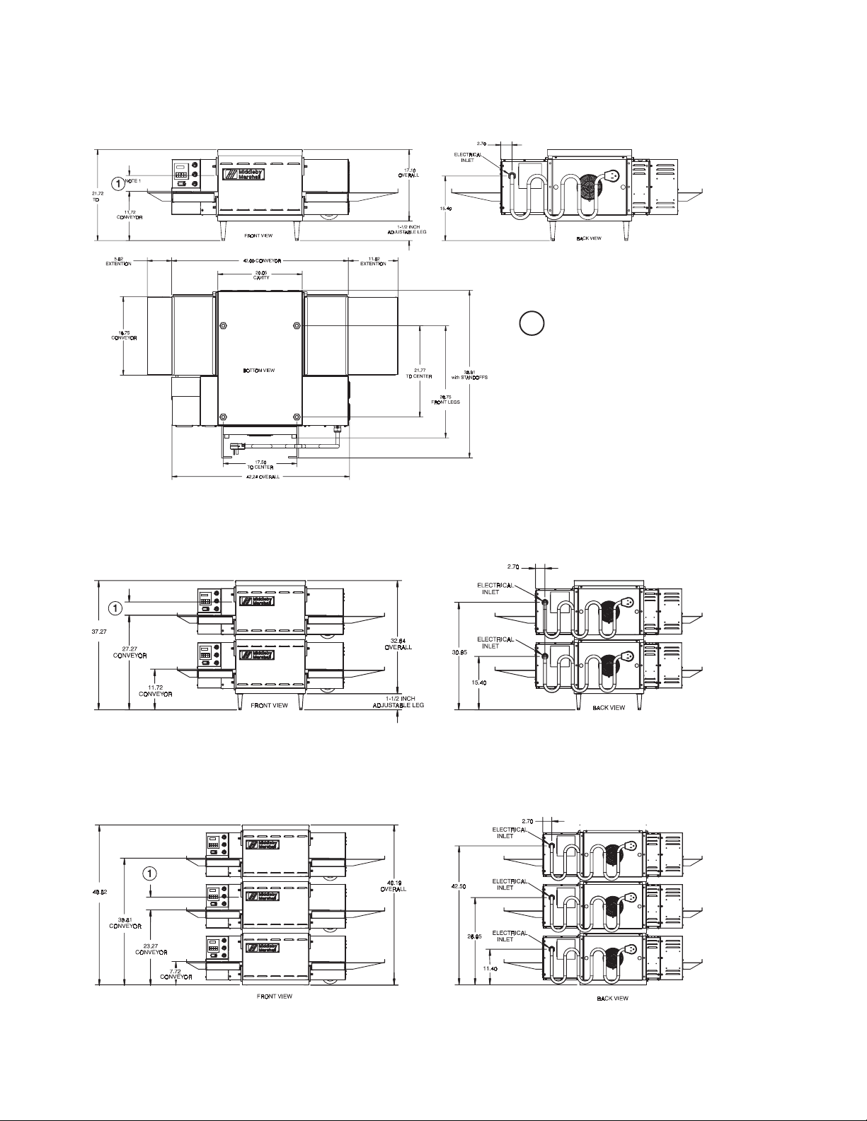
Figure 2-5. MODEL PS520 SINGLE OVEN DIMENSIONS
1
The Opening Height is Adjustable
from 2-1/4 inch minimum to 3-3/4
inch maximum in 1/2 inch
increments.
Figure 2-6. MODEL PS520 DOUBLE OVEN DIMENSIONS
Figure 2-7. MODEL PS520 TRIPLE OVEN DIMENSIONS
PS520E Parts Manual - 10/26/06
2
Page 6
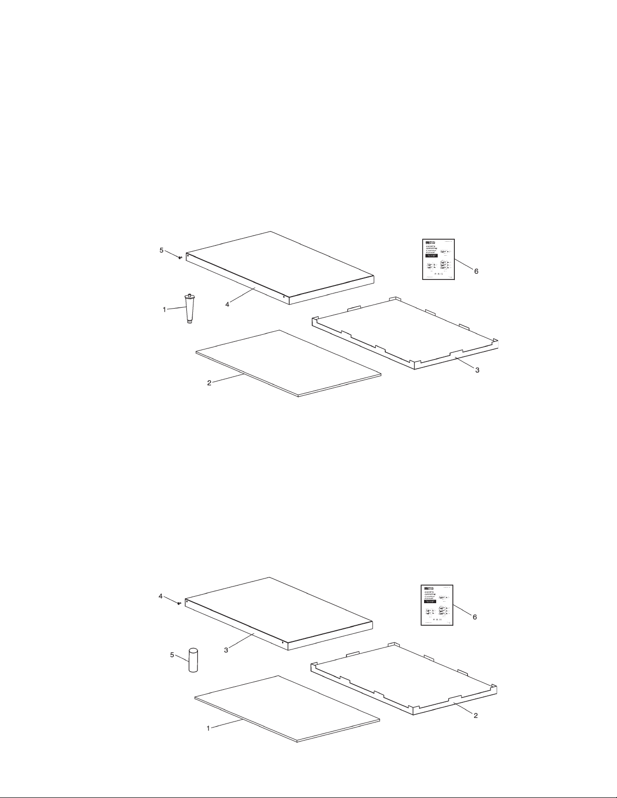
PARTS LIST FOR SERIES PS520 ELECTRIC OVEN
INSTALLATION KIT
Single and Double Stack Ovens
P/N 48397
Item
NO. QTY PART NO. DESCRIPTION
1 4 3101908 Leg 4” AD FT
2 2 48392 Insulation Bottom Tray
3 1 48394 Bottom Tray Weldment
4 1 48396 Top cover
5 4 51387 Screw MSSLT Thread 8-32 x 1/2, 18-8
6 1 52358 Installation & Operation Manual - English
6 1 59476 Installation & Operation Manual - French
PARTS LIST FOR SERIES PS520 ELECTRIC OVEN
INSTALLATION KIT
Triple Stack Ovens
P/N 54593
Item
NO. QTY PART NO. DESCRIPTION
1 2 48392 Insulation Bottom Tray
2 1 48394 Bottom Tray Weldment
3 1 48396 Top cover
4 4 51387 Screw MSSLT Thread 8-32 x 1/2, 18-8
5 4 M3828 Pin, Alignment
6 1 52358 Installation & Operation Manual - English
6 1 59476 Installation & Operation Manual - French
3
PS520E Parts Manual - 10/26/06
Page 7
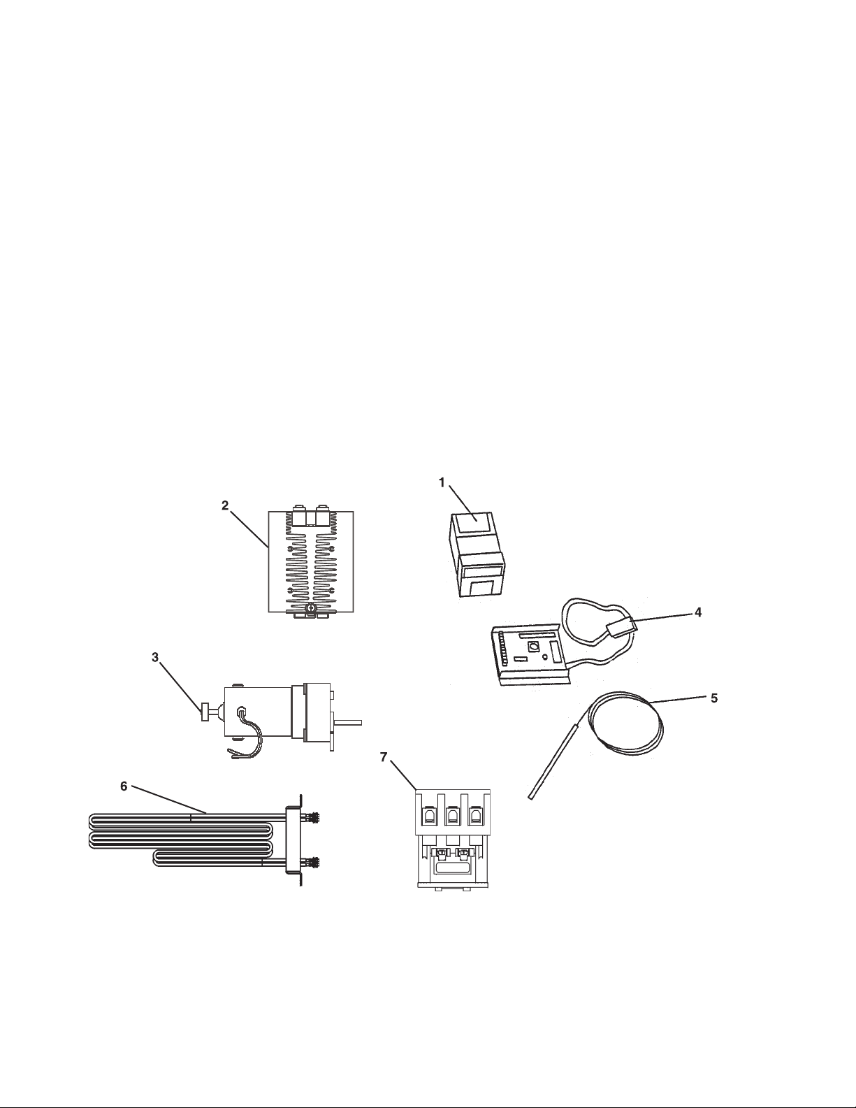
PS520-SERIES ELECTRIC OVEN KEY SPARE PARTS KIT
ITEM PART NO. DESCRIPTION QUANTITY
1 47321 Kit, Temperature Control On/Off PID (58504) 1
2 51402 Relay, 100A 1
3 58390 Conveyor Drive Motor with 2 pole magnet 1
4 58323 Conveyor Speed control 1
5 33812-5 Thermocouple 3
6 50715 Heater Element, 208V 1
6 51017 Heater Element, 240V 1
6 51958 Heater Element, 380V 1
6 51961 Heater Element, 480V 1
7 57408 Contactor 65 amp 3-pole 1
PS520E Parts Manual - 10/26/06
4
Page 8
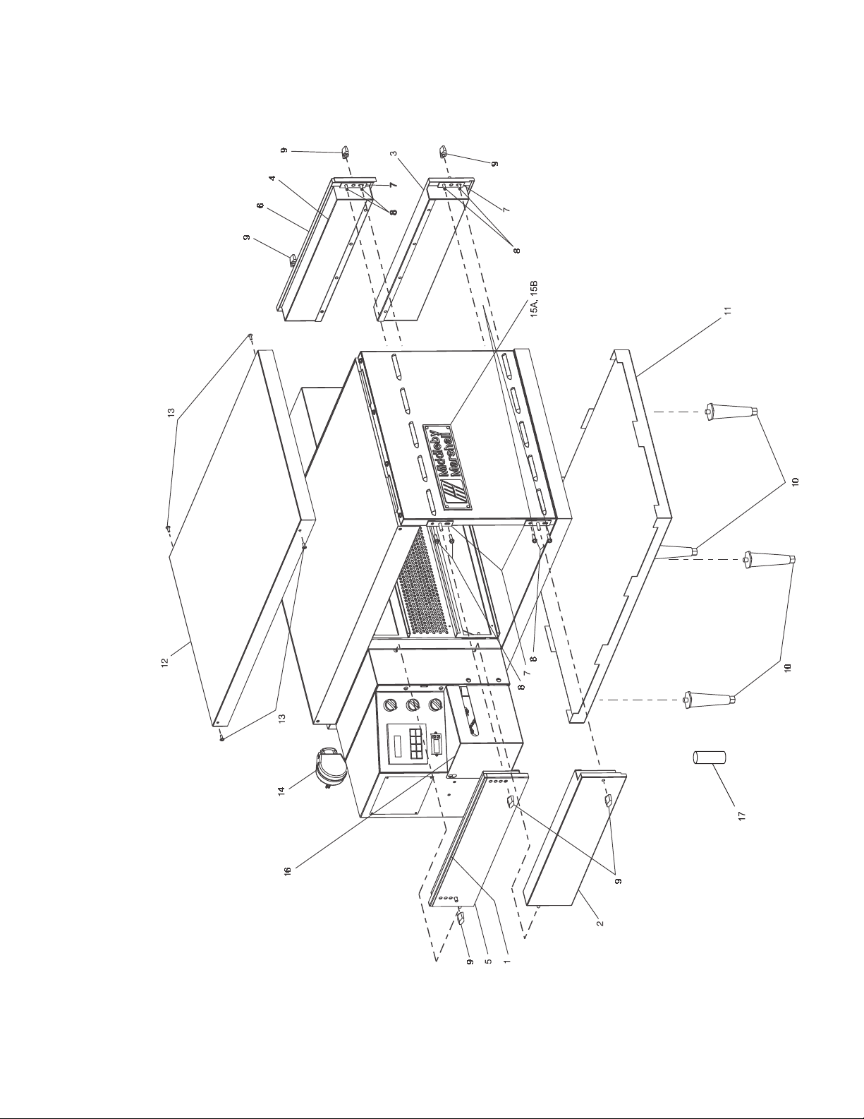
PS520E-SERIES PARTS MANUAL
Front View Of Oven
5
PS520E Parts Manual - 10/26/06
Page 9

PS520E-SERIES PARTS MANUAL
includes item 5 eyebrow
includes item 6 eyebrow
Parts For Front View Of Oven
1 1 48382 Upper LH End Plug Assembly,
2 1 48387 Lower LH End Plug Assembly
ITEM QTY PART NO. DESCRIPTION
PS520E Parts Manual - 10/26/06
3 1 48408 Lower RH End Plug Assembly
4 1 48412 Upper RH End Plug Assembly,
5 1 48378 Eyebrow, Upper LH End Plug Assembly
6 1 48410 Eyebrow, Upper RH End Plug Assembly
7 4 51398 End Plug Mounting Bracket Assembly .875”
8 8 21296-0005 Screw, Hex Head, WSHHD 12-14x3/4 SS BSD
9 6 36452 Nut, Wing-Plastic 1/4-20
10 4 3101908 Leg, 4” ADJ FT (NPS)
11 1 48395 Bottom Tray Assembly (includes insulation part #48392)
6
12 1 48396 Cover, Top
13 4 51387 Scr, MS, SLT THRD 8-32x1/2” 18-8
14 1 M10434 Cordset, 50 Amp 250V, 2P 3W 208/240V Models Only
15A 1 45739 Nameplate, Middleby Marshall
16 1 47861 Cover, Motor
15B 1 59104 Nameplate, Noble Roman’s
17 4 M3828 Alignment Pin (Triple Stack)
Page 10

PS520E-SERIES PARTS MANUAL
View Of Right Hand Of Electrical Compartment
NOT SHOWN - Item 8 RFI Filter
NOTE: Air switch was removed starting with serial #035870306 and after.
7
PS520E Parts Manual - 10/26/06
Page 11

PS520E-SERIES PARTS MANUAL
Parts For Right Hand Electrical Compartment
1 1 or 2 33812-5 Thermocouple, Type “J” Shielded 2.5” x 120”
2 1 28021-0047 Switch, Interlock, 10A NO 2 Pole
3 1 51402 Relay, Heat Sink 100A
4 1 50715 Element, Heating, 208V
4 1 51017 Element, Heating, 240V
4 1 51958 Element, Heating, 380V
4 1 51961 Element, Heating, 480V
5 1 57408 Contactor, 208/240V, 65A, 50/60 Hz
6 1 300-3946 Block-Power Dist 3-Pole
ITEM QTY PART NO. DESCRIPTION
PS520E Parts Manual - 10/26/06
7 1 M10434 Cordset, 50 Amp, 250V, 2P 3W 208/240V Models Only
8 1 45244 RFI Filter - CE Only
8
Page 12

PS520E-SERIES PARTS MANUAL
As viewed from the rear
blower motor spins CCW
Rear View Of Blower Compartment
9
PS520E Parts Manual - 10/26/06
Page 13

PS520E-SERIES PARTS MANUAL
Parts For Rear View Blower Compartment
1 1 28021-0061 Switch, Momentary-10A, NO 2 Pole
2 2 30927 Bumper, Window
3 1 51399 Fan, Cooling, 230V AC, 295 CFM
4 2 52244 Motor, Blower, CW, 208/230V 50/60 Hz With Blower Wheel
5 2 57258 Plate, Air Vent
6 4 7007413 SCR, Shoulder 10-32x3/4 18-8
ITEM QTY PART NO. DESCRIPTION
PS520E Parts Manual - 10/26/06
7 1 31497 Guard-Cooling Fan
10
Page 14

PS520E-SERIES PARTS MANUAL
View of Left Hand Electrical Compartment
11
PS520E Parts Manual - 10/26/06
Page 15

PS520E-SERIES PARTS MANUAL
Parts For Left Hand Electrical Compartment
1 3 46521 Kit Blower Switch (Contains (1) 44697, (1) 44696)
2 3 44697 Contact Block
3 3 44696 Selector Switch
4 1 58323 Conveyor Speed control w/Digital Speed Display
5 1 37503 Digital Speed Control (Display Only)
6 1 47321 Control, Combo 4-20MA (58504)
7 1 28041-0011 Contactor, 208/240V-25A
8 1 31504 Transformer, 230V(P)/120(S), 200VA - Conveyor
9 1 28021-0047 Switch, Interlock, 10A
ITEM QTY PART NO. DESCRIPTION
PS520E Parts Manual - 10/26/06
10 1 33983 Control, Electric, Hi-Limit, 240V
11a 1 39002 Magnet 2-Pole
11 1 58390 Motor, Conveyor Drive With 2-Pole Magnet
12
11b 1 310-0017 Adhesive
12 1 38185 Sensor-Conveyor Pick-up
13 1 35145 Switch, Push-button, Molveno, 250V
14 2 45036 Breaker, Circuit 240V, 3A
11c 1 58484 Kit, 2 Brushes & 2 Caps
15 1 48635 Breaker, Cirucit 240V, 0.3A
16 1 or 2 33812-5 Thermocouple, Type “j”, Shielded, 2.5”x 120”
Page 16

PS520E-SERIES PARTS MANUAL
serial #051471006 and higher.
NOTE: Adjustable conveyor belt feature was added to
NOTE: Adjustable conveyor belt shown
View of Conveyor Parts
13
NOT SHOWN: Complete Conveyor Item #1a, part #59277
PS520E Parts Manual - 10/26/06
Page 17

PS520E-SERIES PARTS MANUAL
Parts For Conveyor
2 2 M4817 Bearing, Rulon
1a 1 59277 Complete Conveyor Assembly - w/Adjustment Feature *
ITEM QTY PART NO. DESCRIPTION
1c 1 48471 Frame Conveyor (no adjustment)
1b 1 59275 Frame Only - Conveyor - Weldment
3 1 M4815 Shaft, Drive
4a 1 59271 Shaft, Idler 18-1/4” *
5 10 M4818 Sprocket, Wire Belt
4b 1 51408 Shaft, Idler 18-3/4”
6a 1 59307 Belt, Wire, Stainless Steel, 18”x87-1/2” *
7 1 58391 Kit, Master Link Front, Middle, Rear
6b 1 M7471 Belt, Wire Stainless Steel
10a 1 310-1212 Master Link Only
10 1 55567 Assy, Chain High Speed w/Master Link
11 1 55217 Sprocket, chain #25-20T-1/2” Conveyor Shaft 25T
12 1 45349 Sprocket, 25B25 w/5/16” Bore - Drive Shaft
13a 1 39002 Magnet 2-Pole
13 1 58390 Motor, Conveyor Drive w/2 Pole Magnet
13c 1 300-2757 Conveyor Drive Motor Only
13b 1 310-0017 Adhesive
13d 1 58484 Kit, 2 Brushes & 2 Caps
14 1 38185 Sensor-Conveyor Pick-up
15A 1 59280 Extension, Conveyor - 6” *
15B 1 51297 Extension, Conveyor - 6”
16A 1 59272 Extension, Conveyor - 12” *
NOTE: ITEMS 1A, 4A, 6A, 15A, 16A, 18A-21A used on models with serial #051471006 and higher
18 2 59276 Screw Adjustment *
19 2 59264 Bushing, Rulon - Idler *
20 1 59267 Idler Guide - Back *
16B 1 51296 Extension, Conveyor - 12”
17A 2 51409 Pan, Crumb Vented - Shipped As Standard
17B 2 48469 Pan, Solid - Optional
21 1 59270 Idler Guide - Front *
PS520E Parts Manual - 10/26/06
14
Page 18

PS520E-SERIES PARTS MANUAL
View of Cart Parts
15
PS520E Parts Manual - 10/26/06
Page 19

PS520E-SERIES PARTS MANUAL
Parts For Oven Cart
#52241 #54596
Single/Double Triple
1 1 1 52237 Wldmt,Base Cart Panel PS520
ITEM QTY QTY PART NO. DESCRIPTION
2 1 1 52238 Panel, Cover Cart PS520
3 2 0 52240 Wldmt, Lower Shelf Cart Panel PS520
4 16 16 A3682 Washer, Lock 5/16”
5 16 16 B10012 Nut, Hex 5/16”-18 ZP
6 4 0 F706A8805 Washer, FLat Rivet Burr 1/4” NP
7 16 16 M0226 Washer, Flat 5/16”
8 4 0 M10435 Scr, MS PH PANHD 1/4”-20 x 2-14”
9a 4 0 M2585 Leg 18” Single and Double
9b 0 4 54657 Leg 5” - Triple Only
10a 2 2 15688 Caster w/o Brake
11 4 4 M3828 Pin - Alignment
10b 2 2 15687 Caster w/Brake
12 4 0 M7958 Nut, Nylon Insert 1/4-20
PS520E Parts Manual - 10/26/06
16
Page 20

17
PS520E Parts Manual - 10/26/06
Page 21

PS520E-SERIES
SCHEMATICS
PS520E Parts Manual - 10/26/06
Drawing 48713 Rev J: Wiring Diagram, E208-240V 50/60/1
18
Page 22

PS520E-SERIES
SCHEMATICS
19
Drawing 52445 Rev J: Wiring Diagram, E380-480V 50/60/1
PS520E Parts Manual - 10/26/06
Page 23

PS520E-SERIES
SCHEMATICS
PS520E Parts Manual - 10/26/06
Drawing 52446 Rev K: Wiring Diagram, E230-240V CE, 1Ph
20
Page 24

PS520E-SERIES
SCHEMATICS
21
Drawing 54661 Rev J: Wiring Diagram, E380-400V CE, 1Ph
PS520E Parts Manual - 10/26/06
Page 25

PS520E-SERIES
SCHEMATICS
PS520E Parts Manual - 10/26/06
Drawing 58158 Rev F: Wiring Diagram, E380-400V CE, 3Ph
22
Page 26

23
PS520E Parts Manual - 10/26/06
Page 27

Page 28

WARNING
Improper installation, adjustment, alteration, service or
maintenance can cause property damage, injury or death. Read
the installation, operating and maintenance instructions
thoroughly before installing or servicing this equipment.
NOTICE
During the warranty period. ALL parts replacement and servicing should be
performed by your Middleby Marshall Authorized Service Agent. Service that is
performed by parties other than your Middleby Marshall Authorized Service Agent
may void your warranty.
NOTICE
Using any parts other than genuine Middleby Marshall factory manufactured parts
relieves the manufacturer of all warranty and liabilities.
NOTICE
Middleby Marshall reserves the right to change specifications at any time.
Middleby is proud to support the Commercial Food
Equipment Service Association (CFESA). We
recognize and applaud CFESA’s ongoing efforts to
improve the quality of technical service in the industry.
Middleby Cooking Systems Group • 1400 Toastmaster Drive • Elgin, IL 60120 • USA • (847) 741-3300 • FAX (847) 741-4406
www.middleby.com
 Loading...