

Page 1
PS670 “WOW” SERIES GAS FIRED:
SPL031707-PF-BD
A MIDDLEBY COMPANY
Parts Manual
with Wiring Diagrams
for domestic ovens
Serial # Code (Ten Digit Code)
First 5 digits - order of production
Sixth digit - model specific
Seventh and Eighth digit- month of production
Ninth and Tenth digit - year of production
March 17, 2007
For Production After April, 2007
XXXXXX0407
Table of Contents: Page 2
email: techsupport@middleby.com
1400 Toastmaster Drive
1-847-741-3300 fax 1-847-741- 4406
© 2006 Middleby Marshall Inc.
www.middleby.com
Elgin, IL 60120
Page 2

Table of Contents
Spec Sheet ...................................................................................................................... 3
Key Parts ........................................................................................................................ 7
Cross Reference of Wiring Diagram Symbols and Part Number(s) .............................. 8
View of Installation Kit(s) and Base Kit(s) ....................................................................9
Parts for Installation Kit(s) and Base Kit(s) .................................................................. 10
Standard Finger Conguration and Part Numbers 60188B ........................................... 11
View of Oven Panels, End Plugs and Window ............................................................. 12
Parts for Oven Panels, End Plugs and Window ............................................................ 13
View of Gas Piping ....................................................................................................... 14
Parts for Gas Piping ...................................................................................................... 15
View(s) of Burner/Blower Motor Assembly ................................................................. 16
Parts for Burner/Blower Motor Assembly .................................................................... 17
View(s) of Front Control Area(s) .................................................................................. 18
Parts for Front Control Area(s) ..................................................................................... 19
View of Rear Compartment and Blowers (Conveyor Drive End Shown) .................... 20
Parts for Rear Compartment and Blowers (Conveyor Drive End Shown) ................... 21
View of “Single” Belt Conveyor ................................................................................... 22
Parts for “Single” Belt Conveyor .................................................................................. 23
View of “Split” Belt Conveyor .....................................................................................24
Parts for “Split” Belt Conveyor .................................................................................... 25
Wiring Diagram, G208-240, 50/60Hz, 1 Phase 54745 Rev. I ....................................... 26
2
Page 3
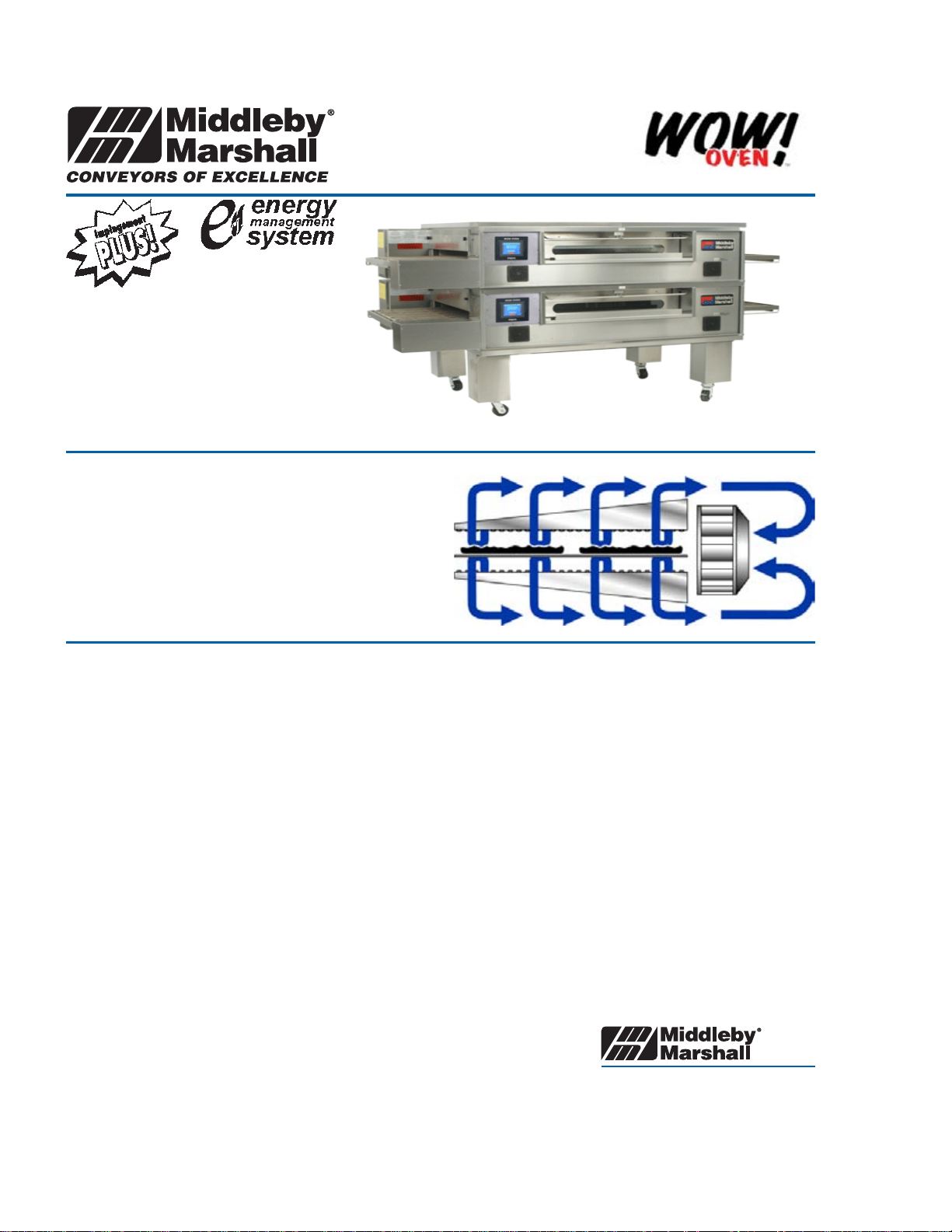
Principle
Middleby Marshall PS Series Conveyor ovens bake both
faster and at a lower temperature than other ovens. Patented vertical columns of hot air move heat aerodynamically instead of using high temperatures. The streams of
hot air remove the boundary layers of cool heavy air which
tend to insulate the product. This gives very rapid baking
without burning. All PS670WOW ovens are designed to
cook pizza 30% faster than other conveyor ovens.
Cleanability
PS670 ovens are designed for easy cleaning. Removable
parts include: crumb pans, end panels, air fingers, and a
folding conveyor belt assembly.
Easily Serviced
Control compartment is designed for quick and easy access. All electrical controls are door-mounted.
Warranty
All PS670 models have a one year parts and labor warranty. Oven start-up and demonstration are included at
no additional charge (USA only).
Ventilation
For installation under a ventilation hood only.
WOW OVEN
A MIDDLEBY COMPANY
1400 Toastmaster Drive
Elgin, Illinois 60120 USA
(847) 741-3300 Fax: (847) 741-0015
www.middleby.com
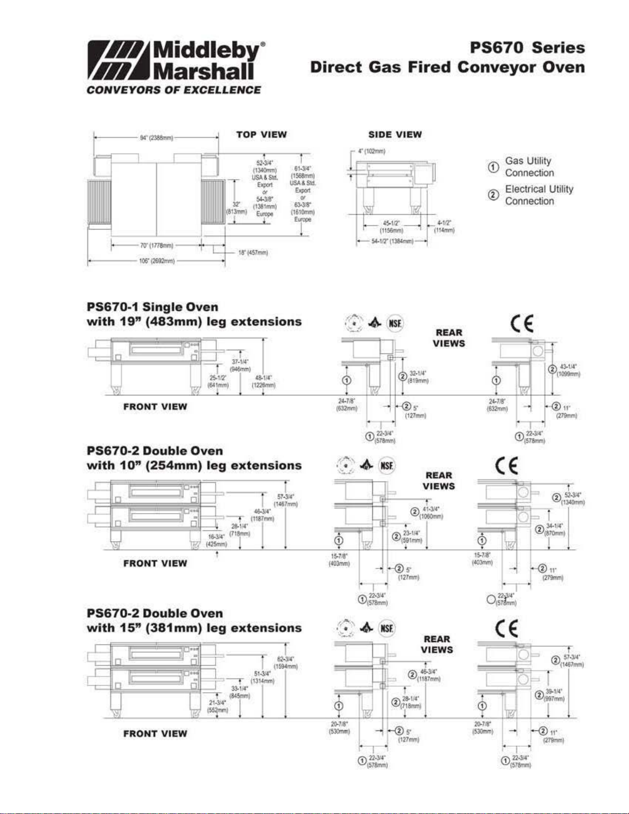
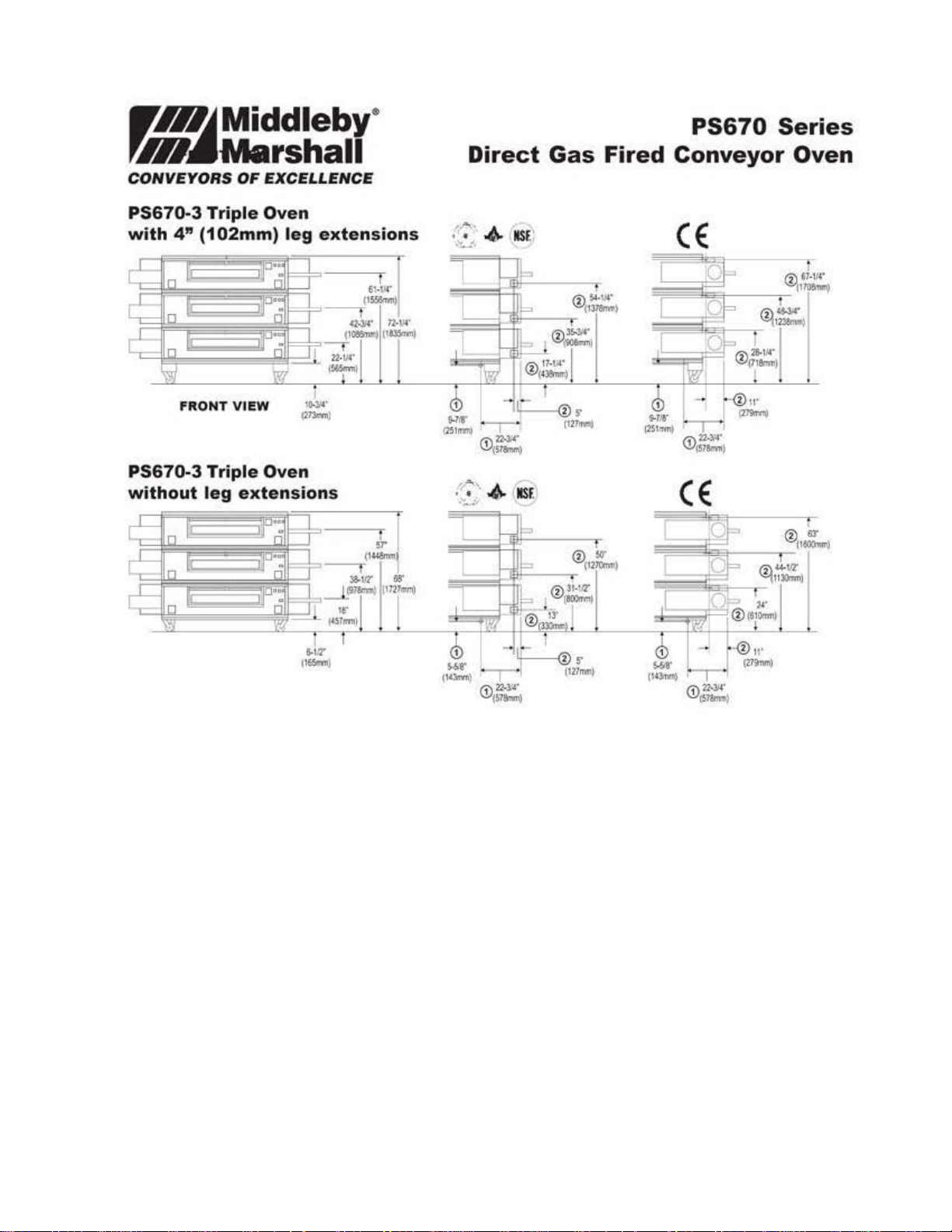
Direct Gas Fired Conveyor Oven
A/A File No.: _____________
Item No.: ________________
Standard Features
• Impingement PLUS! low oven profile and dual air
return
• Patented EMS Energy Management System re-
duces gas consumption and increases cooking efficiency
• 70”/1778mm-long cooking chamber
• 32”/813mm-wide, 106”/2692mm-long conveyor belt
Speed
• Advanced technology air delivering system bakes up
to 30% faster than standard conveyor ovens.
Energy Management System
* The PS670 features an Energy Management System
(EMS) that automatically reduces gas consumption.
Touch Screen Control can be programmed in one energy
saving mode.
* Automatic “energy eye” saves gas when no pizza’s are
in the oven.
PATENTS PENDING
PS670
3
Page 4
WIHJMiddleby•
~~Marshall
CONVEYORS
OF
EXCELLENCE
TOP
VIEW
Direct
Gas
SIDE
VIEW
Fired
PS670
Conveyor
Series
Oven
PS670-1
with
PS670-2
with
19"
FRONT
10"
Single
(483mm)
Double
(254mm)
Oven
VIEW
leg
Oven
leg
extensions
extensions
1C'(1~~
I h
1)
i=
II
1,.,
I~ t'
·
,-
r.. 22·ll4'
~
IS7Bmtrll
"""'~
..,
--Q)_ ..
(1
27tl'nl)
REAR
VIEWS
..
REAR
VIEWS
Gas Utility
1
CD
Connection
<D
El
ectrical UUiity
Connection
CE
CE
FRONT
PS670-2
with
15"
FRONT
VIEW
Double
(381
mm)
VIEW
Oven
leg
extensions
;
,-;
\ 4-
·::-:....:.
4
--..
NS£•
=
REAR
VI
®~··
(11
$7(ml)
EWS
·
CE
[
Page 5
WHI~
Middleby•
PS670
Series
r.III•Marshall
CONVEYORS
PS670-3
with
4"
FRONT
PS670-3
without
OF
EXCEI.I.ENCE
Triple
(102mm)
Triple
leg
Oven
VIEW
Oven
extensions
leg
extensions
I
,,.....
(213m>)
Direct
..
...
.
•
~
.
..
·-·
$.111'
--
!l'lml
"'
w
::;,'
·--
#=~
Gas
...
.._,.. tiiS
F.
·
i,.,;,
.
<sr~
4 INS['
@ liT
~---;~
Fired
Conveyor
CE
CE
(12~1
Oven
5
Page 6
WIHJMiddleby
'711
CONVEYORS
..
Marshall
OF
EXCEI.I.ENCE
$
Direct
Gas
Fired
PS670
Conveyor
Series
Oven
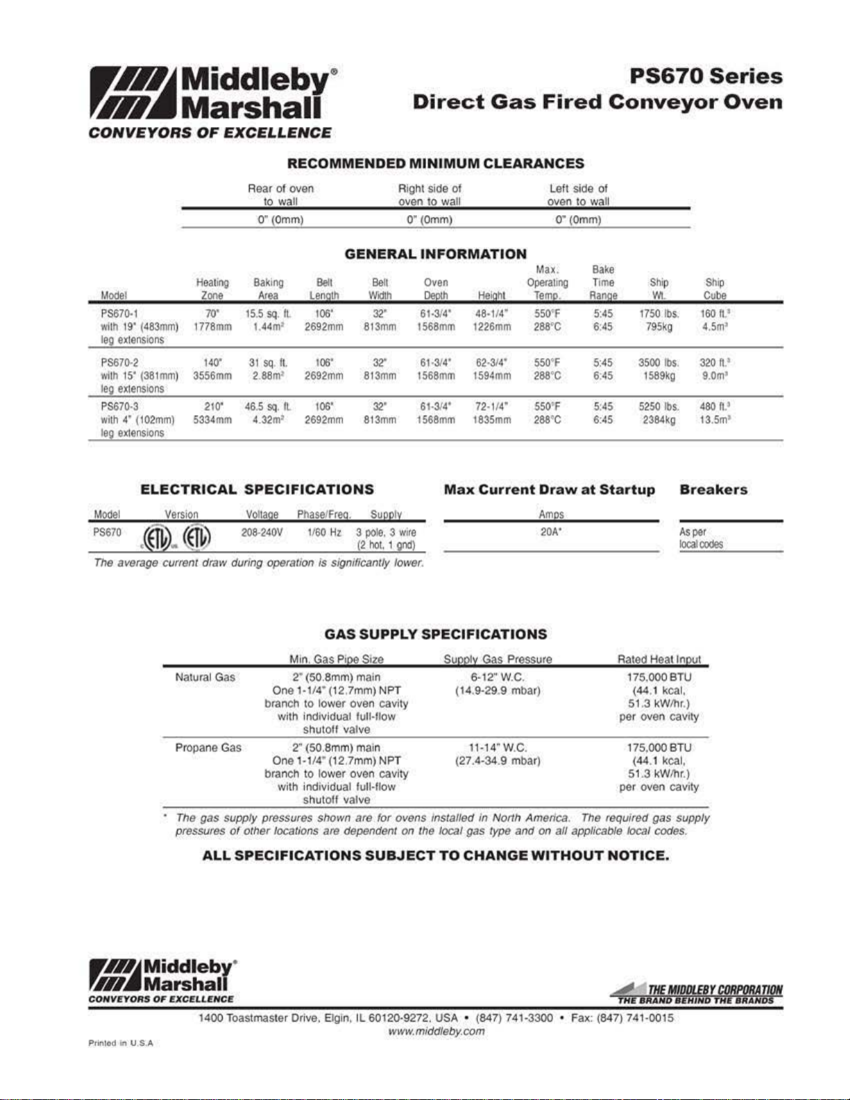
RECOMMENDED
Rear
of
oven Right side ol Loll side
to wall oven
O"(Omm
mm
Baking
Area
15.5
L44m
81
2.
46
.5 sq.
4.32m
VO!la
208-240V
Mode
l
PS670.1
wllh
t9'
(483mm)
leg
extensions
PS670.2
wt
lh 15'
(381mm)
leo
extensions
PS670·3
with
4'
(102mm)
leg
eXIenslons
EL
Model
P$670
The average current draw during operation
HeaiJI"'Q
Zone
70'
177B
140'
3556mm
210'
5334mm
ECTRICAL SPECIFICATIONS
version
sq.
sq
86m
pe
1
ft.
1
2
IL
IL
)
2692mm
2692mm
2692mm
P
haseJF
GENERAL
Belt Belt
Le
nolh
106'
813mm
106'
813mm
106'
1160
is
813mm
reo
.
Ht
3
pole.
(2
significantly lower.
Vild1h
32'
32"
32'
su
pply
hot
, 1
MINIMUM
10
wall
Omm)
0" (
INFORMATION
Oven
!lep!h
61·314'
1568mm 1226mm
61·314'
1568mm 1594mm
61·314'
1588mm 1835mm
Max
3
wire
gnd)
CLEARANCES
oven
O"(Omm)
Max
.
Helehl
48·114"
62·314'
72·114'
Current
Ope<aung
Tem
p.
550'F
286\)C
550
'F
286()C
550
'F
288
'C
Draw
Am
20A'
s
to
at
waJI
Bake
Time
Ranoe
6:
5:45
6:
6:45
ol
5:45
45
45
5:
45
Startup
Ship
v~
1750
795kg
3500
1589kg
5250
2384kg
.
lbs
.
lbs
.
lbs.
Breaker
Asper
localoodes
Shi
p
Cube
160
n.~
4.5m'
320 ft.'
9.0m
480 ft.'
t3.5m,
1
s
NaMal
Gas
Propane Gas 2" (50.8mm) main
The
gas
pressures
supply pressures shown
or
ALL
rmjMiddleby
rHI~Marshal
C
OHV~Y
Oif$
Prinlod
OF EXC!
tn U S.A
U.LHCI!
1400 Toastmaster
One 1-114' (12.7mm) NPT
branch to
wi
One
branch
wi
other
locations are dependent
SPECIFICATIONS
·
GAS
SUPPLY
Min.
Gas
Pioo Srz
2'
(50.8mm) main
lower
lower
oven cavity
oven cavity
al
full-flow
valve
are
th
individual fun-now
shutolf valve
Hl4"(12.7mm) NPT
to
th
individu
shutoff
SUBJECT
Dr
ive.
8gin.
IL 60120·9272. USA • (847) 741·3300 • Fax: (847) 741·0015
SPECIFICATIONS
e
for
ovens installed
on
Supoty
(1
(27.4·34.9 mbar)
lhe
local
TO
www.middlsby.com
6
Gas
Ptessute
6-12"W.C.
4.9-29.9 mnar)
w.c.
11-14"
in
Nol1h America. The required
gas
type
and
on
all
applicabl.s
CHANGE
WITHOUT
Rated Heat
175.000BTU
(44
.1 kcal.
51.3 kW/Ilr.)
pe
r
over\
175.000BTU
(44.1 kcal.
51.3
kWfllr.)
pe
r oven cavity
gas
/oc81
codes.
NOTICE.
Input
cavcty
supply
Page 7
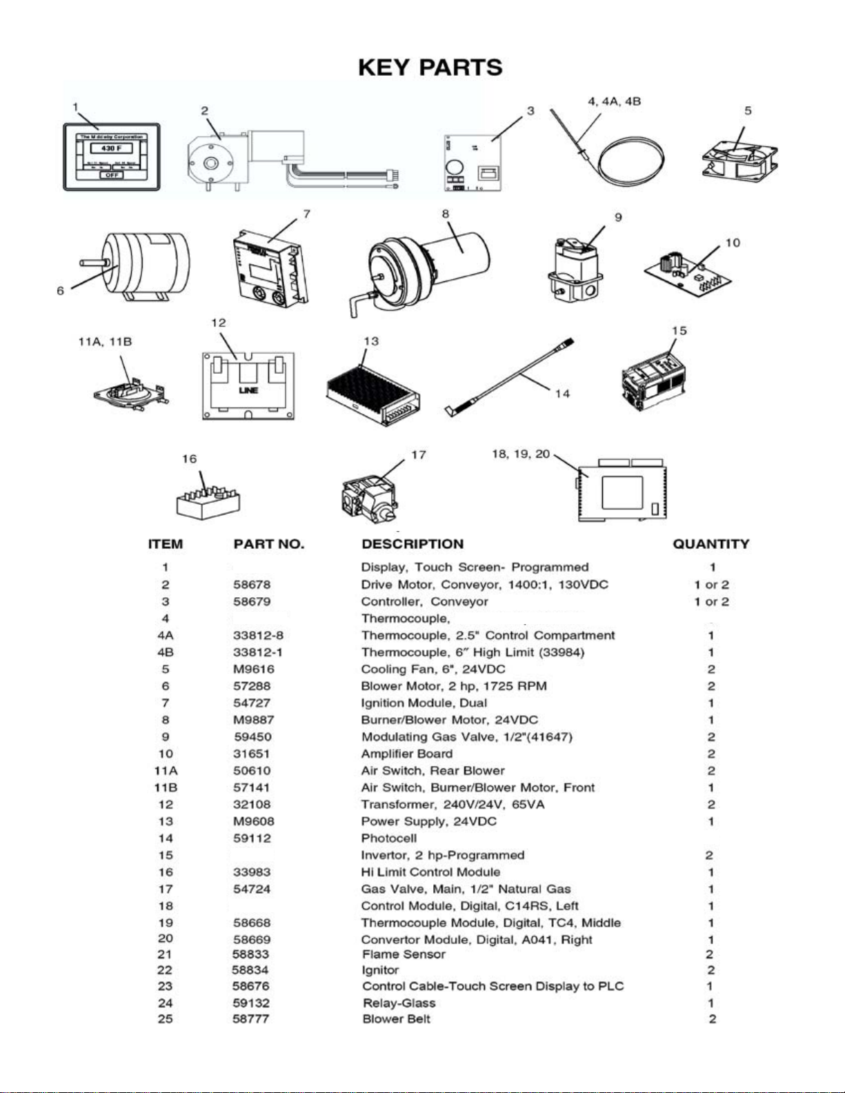
60088
33812-6
60126
60128
12" Temp. Control
4
1
7
Page 8

CROSS REFERENCE of WIRING DIAGRAM SYMBOLS and PART NUMBERS
• Air Switch 1 -Rear Right .........................................50610
• Air Switch 2 - Rear Left ..........................................50610
• Air Switch 3 - Front Right .......................................57141
• Blower Motor–Left ..................................................57288
• Blower Motor–Right ................................................57288
• Burner Blower Motor ............................................ M9887
• Circuit Breakers
• CB1 - 15A ...............................................................45037
• CB2 - 15A ...............................................................45037
• CB3 - 15A ...............................................................45037
• CB4 - 15A ...............................................................45037
• CB5 - 3A .................................................................45036
• CB6 - 3A .................................................................45036
• CB7 - 1A .................................................................45644
• CB8 - 1A .................................................................45644
• Cooling Fan LH .....................................................M9616
• Cooling Fan RH .....................................................M9616
• Controller 1 DC ......................................................58679
• Controller 1 DC (split belt) ......................................58679
• Conveyor Motor ......................................................58678
• Conveyor Motor (split Belt) .....................................58678
• Dual Burner ............................................................54719
• Converter Module - Digital A041, Right ..................58669
• Control Module - Digital C14RS-A, Left .................60088
• Thermocouple Module - Digital TC4, Middle ..........58668
• Gas Valve ...............................................................54724
• Green Light (Reset Button) ....................................35145
• GT30 Display .........................................................60128
• Ignition Module, Dual .............................................54727
• Inverter - 1 Left, 2HP ..............................................60126
• Inverter - 2 right, 2 HP ............................................60126
• Switch(es)
• LS1 (LH RR), Momentary ............................. 28021-0061
• LS2 (RH RR), Momentary ............................ 28021-0061
• LS3 (RH Front), Inter Lock ........................... 28021-0047
• LS4 (LH Front), Inter Lock ............................ 28021-0047
• Reset Button ..........................................................35145
• Mod Valve 1 (41647) ..............................................59450
• Mod Valve 2 (41647) ..............................................59450
• Photocell 1 Entrance ..............................................59112
• Photocell 2 Exit ......................................................59112
• Power Supply ........................................................M9608
• Relay ......................................................................59132
• Signal Amplier 1 ...................................................31651
• Signal Amplier 2 ...................................................31651
• TB1 RR LT (3 Pole) ................................................44390
• TB2 RR LT (3 Pole) ................................................44390
• TB3 RR RT (3 Pole) ...............................................44390
• TB4 RR LT (8 Pole) ................................................31047
• TB5 Comp Brkt (4 Pole) ........................................M0593
• TB6 Comp Brkt (4 Pole) ........................................M0593
• TC1 - 6” High Limit (33984) ................................ 33812-1
• TC2 - 12”, Oven Temp. ....................................... 33812-6
• TC3 - 12”, Oven Temp. ....................................... 33812-6
• TC4 - 2.5”, Control Compartment ....................... 33812-8
• XFMR1 - 240V/24V 65 VA ......................................32108
• XFMR2 - 240V/24V 65 VA ......................................32108
• High Limit ...............................................................33983
Wiring Diagram on Page 26
8
Page 9
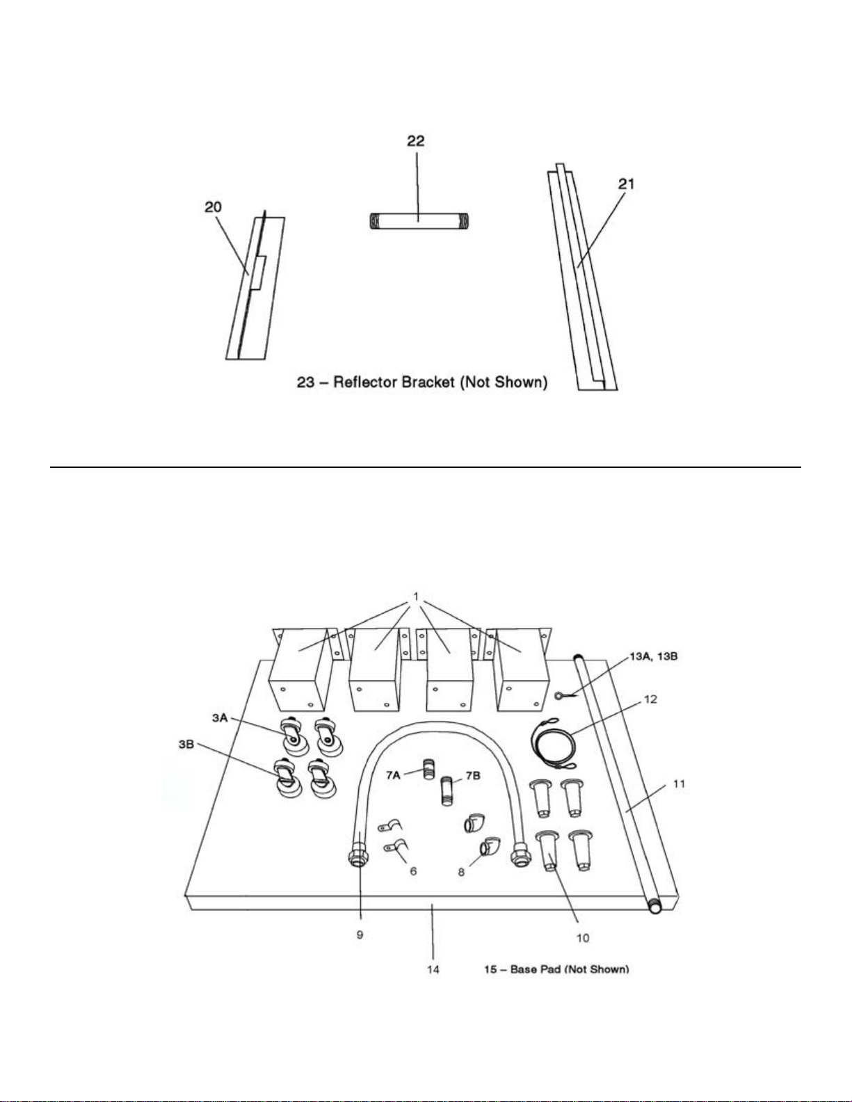
VIEW OF INSTALLATION KIT (PART NUMBER 59057)
VIEW OF BASE PAD KIT
9
Page 10

Parts for INSTALLATION KIT (Part Number 59057)
59419
10
Page 11

IAIAIBIEIXIEIBIAIAI
I I I
45084
A=
WLDMT,OTR
35000-1366
45083 WLDMT,RAISED MANF W/PERF
PLA
PL T W/EXT
TE,INNER PERF L6
TAB
Sll4
ALUZ
BAF
11
11
< '>
I I
.
11!1
'
SYMMETRICAL FINGER CONFIG.
AVG CONTROL TICS: 4 USED
ENT: TOP INNER
EXIT:
RPM= 2100RPM, INVERTERS
BOTH SIDES END PLUGS
PARTITION K
lclolxlolcl
TOP
& OUTER LOCATIONS: 12" PROBES
INNER & OUTER LOCATIONS: 12" PROBES
IT
RAISED PIN 59834
HAVE
SET@
63HZ
.DIVERTERS
I I I I I
39225
B=
C=
D=
. . 3521 0-0520 PLA
Ea
WLOMT
35000-1366 PLATE,INNER PERF L6
45083 WLDMT,RAISED MANF
37900-0051 PLATE,OUTER S/L6
35000-1366 PLATE,INNER PERF L6
36449 WLDMT,MANF
44476 WLOMT,OTR PLATE L 18
43034 WLDMT,MANF W/PERF BAF
35210-0535 PLATE,BLANK PRTL 2.75
,PLT
OTR
W/PERF
TE
,INNER PERF L
S/L6
W/EXT
ALUZ
W/PERF
BAFFLE
W/14
18
ALUZ
TAB
BAF
ALUZ
ALUZ
ROWS
ALUZ
l18
UPR
l===i=
=}="
----==
=
=~
~==
=========-
-,
+
~~
~~~~~~~~~~
-~"~
--~~--
---
ICONFIG,FNG.RPS670G
'
~
·
.
188
·· · B I
_·_,~~·
,___,,
~~'------=-
· ·:
rs
·~·
·
'--'.
.. · . _
·
lr-~Middleby-
U.~Marshall
_j
CONVI!YOIIB
S!D
OF
Bt:ai.EIICa
.
_j
Page 12

47
48 FILTER-ONLY
46
12
Page 13

49 1 59834 Partition Kit
50 1 59456 Partition Raised
51 2 59464 Bottom Partition
59838
59049
13
Page 14

View
of G.AS
CONTROLS RIGHT HAND BURNER
PIPING
14
6
2
CONTROLS LEFT H
I
4
DUAL BURNER ASSE
FITS HERE
4
AND
BURNER
MBLY
Page 15

QlY
ITEM
1 4 23051-0003
2
. P/N
1 23051-0012
Parts for
DESCRIPTION
UNION, 1
UNION,
GAS
1-1W
PIPI
/2"
NG
15
3
4
5
5A 1 28092-0018 SPRING FOR LPCONVERSION
----
6 1
1 23115-0009
2
1 54724
59450
----------------
42410-0016 BRACKET/CLAMP
MANUALONIOFFGASVALVE,1/2", BALL
MODULATINGGASVALVE.
VALVE, COMBINATION,
------------
112" (4164
112"
-NATURAL GAS
---------
7)
Page 16

(1/8” GAP)
16
Page 17

.118
17
Page 18

26
1, 1A, 9
1, 1A, 9
View(s) of FRONT CONTROL AREA(S)
27
18
Page 19

Parts for FRONT CONTROL AREA(s)
ITEM QTY. P/N DESCRIPTION
1 2 310-2458 FILTER/GUARD, FAN
2 2 31651 AMPLIFIER BOARD
3 2 32108 TRANSFORMER, 240/24V, 65VA
4 1 60128 TOUCH SCREEN DISPLAY
5 1 54727 DUAL IGNITION MODULE
6 1or 2 58679 CONTROLLER, CONVEYOR
8 2 M0593 TERMINAL BLOCK, 2-POLE
9 2 M9616 COOLING FAN, 24VDC
10 1 33983 HI-LIMIT CONTROL
11 1 57141 AIR SWITCH, FRONT, BURNER/BLOWER
12 1 60088 CONTROL, (LEFT-HAND), DIGITAL, C14RS -PROGRAMMED
13 1 58668 THERMOCOUPLE (MIDDLE), CONTROL, TC4
14 1 58669 CONVERTER, (RIGHT-HAND), A041
15 1 M9608 POWER SUPPLY, 24VDC
16 1 35145 RESET SWITCH W/GREEN LIGHT, HI-LIMIT
17 2 60126 INVERTOR -PROGRAMMED
18 2 45644 CIRCUIT BREAKER, 1 AMP
19 2 28021-0047 SWITCH, INTERLOCK
20 4 45037 CIRCUIT BREAKER, 15 AMP
21 2 45036 CIRCUIT BREAKER, 3 AMP
22 1 33812-8 THERMOCOUPLE, 2.5″ x 60″, CONTROL COMPARTMENT
23 4 33812-6 THERMOCOUPLE, 12″x120″ REAR OF OVEN
24 1 33812-1 THERMOCOUPLE 6″ (HIGH LIMIT) REAR OF OVEN (33984)
25 1 59132 RELAY, DPDT, 24VDC COIL
1A 2 310-2468 FILTER ONLY
26 1 58764 MIDDLEBY LOGO
27 1 59085 LABLE - MIDDLEBY MARSHALL WOW OVEN
19
Page 20

20
View(s)
of
REAR
COMPARTMENT
AND
BLOWER
(CONVEYOR
DRIVE
END
SHOWN)
2
ITEM 39
ITE
ITEM
ITEM
ITEM 43
ITEM 44
ITEM 47 PHOTO
ITEM
MOME
NTAR
M 40
AIR
SWI
TCH. NOT SHOW
41
ALUMINUM
42
TUBING. SILICONE. N
THERMOCOUPLE. NOT
THER
MOCOUPLE. N
CELL
48
MOUNTING
Y SWI
TCH
. N
TUBING. NOT
OT
OT
BRACKET.
PHOTO
OT
SHO
WN
N
SHOWN
SHOWN
SHOWN·12'"
SHOWN·6"
CELL
NOTE: IDENTIFY THE DEFECTIVE INNER FROM THE DEFECTIVE OUTER BEARING ITEM 14 PER ENGINEERING’S REQUEST
(THESE PARTS ARE TO BE RETURNED FOR OUR INSPECTION)
Page 21

28 4 A3682 LOCKWASHER, SPLIT 5/16″
ITEM QTY. P/N DESCRIPTION
Parts for EACH REAR COMPARTMENT AND BLOWER
31 1 57296 PULLEY, 5.6″
32 1 57297 INSERT, 5/8″
33 1 43024 EXTENDER, FAN
34A 1 27399-0008 FAN BLADE, CW, 8″, CONVEYOR DRIVE END
34B 1 27399-0009 FAN BLADE, CCW, 8″, IDLER END
35 1 57316 BRACKET, MOTOR SUPPORT
SHAFT SEAL, PTFE
36 1 57298 INSERT, 1-7/16″
37 1 Contact Factory KEY, 5/8 x 1
38 2 57325 RING
39 1 28021-0061 SWITCH, MOMENTARY
40 1 50610 AIR SWITCH
41 A/R 15125-0002 ALUMINUM TUBING
42 A/R 22450-0297 TUBING, SILICONE
43 4 33812-6 THERMOCOUPLE, 12″ x 1 2 0 ″, REAR OF OVEN
44 1 33812-1 THERMOCOUPLE 6″ (HIGH LIMIT) (33984)
45 1 41575 MOUNTING BRACKET
46 1 44550 SUPPORT BRACKET
47 1 59112 PHOTO CELL, 24V DC
48 1 59108 MOUNTING BRACKET, PHOTO CELL
2 1 37210-0124 PLATE, INLET RING
1A 1 22521-0005 BLOWER WHEEL, IDLER END
1B 1 22521-0006 BLOWER WHEEL, CONVEYOR DRIVE END
ITEM QTY. P/N DESCRIPTION
3 4 21211-0001 SCREW, CAP HEX HD 3/8″-16 x 3″
5 10 21422-0001 LOCKWASHER, SPLIT 3/8″
6 4 35210-0576 SPACER
7 1 35210-0541
8 1 37210-0101 PLATE, SHAFT SEAL INNER
12 1 57323 SHAFT BLOWER
13 1 35210-0286 KEY, BLOWER WHEEL
14 2 57321 BEARING
15 4 57320 SPACER, BEARING
16 4 2000535 SCREW, CAP HEX HD
17 4 A6235 FLATWASHER, 7/17″
18 4 21121-0013 HEX NUT, 1/2″-13
19 1 57295 PULLEY, 5″
17A 4 21422-0016 LOCKWASHER
21 1 58777 BELT
25 1 57288 MOTOR, BLOWER 2HP
26 1 59133 BRACKET, MOTOR MOUNTING
27 4 6673 SCREW, CAP HEX HD 5/16″-18 x 1″
21
Page 22

\\
II
View of Single-Belt Conveyor
..
. . .
~~·
·\
· .
. . . :
••
V' •••
...
....
·.
..
.:·
. t ·'
·.
. . .
..
.. ··"
•• c ......
(<4
I . . . \
·. = .··
. 2
·.·
. · r, •
.·
··
{
N
-:··
•'
..
. .
. · "· .
t ...
-:·
....
••
.
·
22
Page 23

Parts
for
Single-Belt Conveyor
ITEM
OTY
2 1
3 1
4
s
6 8
7
8
8 8
9A 1
------------------------------------------
9B
10
11
12
4
13
23
14
15
6
17
2
18
2
19
2
20
2
21
PART NO.
37210-0117
37210-0046
37210-0116
35210-0429
35210-0491
F716A8805
21176-0001
22450-0265
33900-0032
51380
350()0..10
22229--0003
22034-{)003
37000-0413
35000-1008
35000-10
11
54947
12
WEL.OMENT.CONVEYORORIVE
WELDMENT.CONVEYORCENTERFRAME
WELOMENT.CONVEYORQ.ERFRAME
PIVOT
PlATE
BUSHING.CONVEYORAIWSTMENT
WASHER.
LOCKNUT, HEX
CONVEYOR
CONVEYOR
MASTERLINKS
SHAFT
SPROCKET,
BUSHING, BRONZE
BRACKET, IDLER SHAFT ADJUST
SC
BRACKET.
SHAFT. DRIVE
EXTERNAL
MASTERUNK.LEFT
MASTERUNK.CENTER
MASTERLINK, RIGHT
, IOlER
REW, CONVEYOR
SHAFT
DESCRIPTION
FRAME
TOOTH
1/4•
114"·20
BELT, COMPLETE.32"Wx206'1.
BEL
T.
32'"W
x 12"l
(0.8
1x
0.30m)
KIT
. 32"
(0.81m)
BELT
(INC.ITEMS
CONVEYOR BEL
SUPPORT
T
3/4" 0.0. x
TENSION
518"
1 .D.
MENT
ADJUSTMENT
11-13)
ITEM OTY
22
27 2
42
24
25
26
28
29
30
31
32
33
35
40
41
43
44
6
1
2
2
1
1
1
1
2
1
PART NO.
22229.0003
22011·0013
22034·0003
3500().1080
54947
35000-10
22152
4240
2227
22152.0018
35210.()640
.()()
0-0164
3.()01)1
58678
55027
55028
13
17
30004
M1
0098
4
5035
DESCRIPTION
SPROCKET, CONVEYOR
COLLAR. SHAFT. WITH
BUSHING,
SPACER.
BRACKET.SHAFTSUPPORT
ADAPTER.
SPROCKET. DRIVE
~
ASSEMBl Y.ROUERCHAIN(62UNKS)WITHMASTERUNK
SPROCKET,ORIVE MOTOR,st8•80Re,
~
AOAPTER.ORIVEMOTORWITHSETSCREW
ORIVEMOTOR.BRUSHL.ESS,1400
ENDSTOP.CONVEYOR,29-1/4"LONG
REARSTOP.CONVEYOR,
CRUMB
HARNE
MOUNTINGBRACKET,DRNEMOTOR
BRONZE
NYLON
DRIVE
MASTERUNK.
PAN
SS, WIRE
BELT
SET
314"
0.0
1-1/4"
0.0. x
SHAFT
SHAFT
ROLLER
SCREW
. x
518"
1 0.
3/4"1.0.
.
518"
BORE. 9T, WITH
CHAIN
:11
18"LONG
1ST,
WITH
30VOC
SET
SET
Page 24

...
0
>-
<1>
>
s:
0
0
r
"""'>70
I
I
I
I
I
I
I
I
I
I
I
/
/
I
I
I
/
I
I
I
/
/
/
./
~
·' .
______
I
_/
24
.
--
/
I
I
/
/
I
/
I
/
/
I
I
I
I
I
/
/
/
I
I
.
.
. .
..
.
..
•
··.
.
·~
Page 25

Qll
ll~Da
1
2 1
1 37210-0
3
4
5
6 8
eaBltUl
3721Q-Q117
37210-0046
11
3§210-Q429 PIVQTPLATE
35210-0491 BUSHING, CONVEYOR ADJUSTMENT
WE
LDMENT,CONVEYORCRIVEFRAME
WEUJMENT,CONVEYORCENTERFRAME
6 WEUJMENT CQNVEYORIOLERFRAME
7 8 F716A8805 WASHER EXTERNAL TOOTH
8 8
9A
----------------J
2
98
10
15 1
16
11
25
20
21 2
22
23
24 21415-0001 FLAT WASHER.
25
2
14 1
1
8
19
2 22034-0003 BUSHING BRONZE 314" O.D. x 518"1.0 .
2
2 54947 BRACKET SHAFTSUPPDRT
1 42400-0355 SHAFT. DRIVE,
.21176-0001 LOCKNUT, HEX 1
22450-0271
33900-Q037 CONVE
51382
4240
0·035
21415·0001 FLAT
3~00Q·1535
22229·0003 SPROCKET CONVEYOR BELT
37000-0413
35000-100~
35000-1536 SH
OONVEYO
~~~~=~~~~~ml
MASTERLIN
SHA
4
SHAEI,IOLER, FRONT, 1
BRACKET, IDLERS HAFT ADJUSTMENT
SCREW,CONVEYORTENSIONAOJUSTMENT
RBE
LT,COMPLETE.
YOR
BELT, 1
KS
FT
IDLER REAR 32·314"
WAS
HER, BRQNZE,
REAR
AFT
.DRIVE ,FRONT, 17-
Parts for "SPLIT" Belt Conveyor
c'~~B,E:liCtll
1/4'
14'-20
_____________
5"Wx
12'1. (0.38 x 0.3Qml
KIT, 1
5'
BR
{0.81m} B
, 35-1/
ONZE,
ELT
1"
0.0
. X 1/2" 1.0.
§-~/8
"
3"
1"
0 .0 . X 1/2" 1.0.
3/4"
(INC.ITEMS 11-13!
QD:
II~rd
2§
27
2~
2~
30
31 2 54947 BRACKET SHAFT SUPPORT
32
33
~
2
2 35000-1
1 35900-0023 BUSHING SPLIT BEL TORI
2
eaBitUl
2222~-QllQ~
35000-1531
22Q11
-Qll14
22~·QllQ~
080
22
152-
0017
§PRQI;
SPACER NYLON FfTSBETWEENSPROCKET
I;QLLA!3,
B!,!§HIN!Z, BRQNZ
SPACER NYLON 1-1/
SPROCKET.ORIVESHAFT,5/8" BORE,9T, WITH SET
aE~Bieiic~
KET, I;QNVEY
!2E
LIT LQI;KIN!Z
!:i
QR
~£4"Q,Q
4"
SCREW
RO
34 42400·0164 ASSEMBLY,
35
36
37
2 22273
2
42410-0128 ASSEMBLY, ROLLER CHAIN COMPLETE {48 LINKS)
MASTERLINK
SPROCKET.ORIVE MOTOR,
22
152·
-00
0018
01
LLER CHAIN
RO
LLER CHAIN
SCREW
38
40
45
46
47
48
49
2
2 30004 CRUMB PAN
2
35210-0640 ADAPTER DRIVE MOTOR WITH SET SCR
OR
58678
55027
55028 REARSTOP.CONVEYOR
M10098 HARNESS. WIRE
45035 MOUNTINGBRACKET,ORIVEMOTOR
IVEMOTOR,BRUSHLESS.1/8HP11400
END
STOP CONVEY
OR
BELT
. x ~/~'
0 .
0. x 314"1.0.
VE
SPROCKET
COMPLETE
518
"BORE. 1ST, WlT
29-1/
4"
18'
"
1.0
.
I62LINKS}
HSET
EW
;1
Page 26

•••
~----------------~w
•
Hlii
LKT
COM'! I ,jCDM2
LS1
LHRR
t«ll
"
u
I I
'I
• •
llll2
G_
H_
1
__
lint
.,
DATE
I-
..
_
,_
•••
-CIILGIIIIINTCII
0111111
lmE1BI
111M' I CIU1M
-I'IIIITUMILINI!Ij
0111~
_...._,
CIII'D-
OIIUC
-
REVISION
11-.
DESCRIPTION
Nft.l~llll
I'IIIITIIIN
BY
CHK
IIIII
-
FC
_,
AI-
DATE
~
11'111,..
Dlltv..
26
.
LOAD
kd
=
r"""'""
L1
UIE
L2
!It
27
XFI'R1
LEFTI
PRIMARY
:mY
SDJ60Hz
SE!]JNJARY
6SVA
2'V
FPO-A0'1
["
CDI
[
~
CDI
[c:.~~
[:~~
~
~I
117
CONTRW.ER
IB.-2302
ILIC
1tll
~
f;l
a
~
1
:
111
,
IQ
IL_
IL~~~~----~~---_-_-_-_-_-_-_-_-_-_-_-_-_-_-_-_-_-_-_-_-_-_-_-_~~--~--~
DC
~.n
f-Orr
0~
r-o~
n-
01'
L2
0'12
L...!!..!!._
00000
ooooo
1
Ll
WD
LABEL
PIN
56613
TOIBWj[E
IIATBUIL
l--
---------\
FINI..
- IIEIICED
M
®©
ALL
LILLESS
111"121111
lBI
Ml/21111
WD,G208-240t50!60!1
DI-LONS
w.
IN I NOES
OTIBWII!E SPEtiFIEIJ. 5 4 7 4 5
DO
_!IC!!_
StALf
DIIIIWINii
!PB:IFIIII
MliLES
lEt
.........,
11!1
I
PART
.I
.XI
.1001:
llltl,_
NO
IJUSS
THIS IJIAWIIE IS toiFIDEIITIAL
• 1.0"'
•.IBD
•.01!5
••
oos
THE
UOO
Elgin.
PIICI'EIITY
Toaat•catl!r
llllnalo
147-7~
1-3300
Of
CORPORATION
Dr I we
toll120
MIDDI.EBY
PS870!770
SHT
[
1
OF
AND
IRE¥
1
I_
Page 27

 Loading...