

Page 1
PS536GS
Gas
Domestic, Std. Export & CE
ENGLISH/French/Spanish
P/N 50236
Rev. B • V1 • 10/04
Price $30.00
PS536GS Gas Ovens
Models:
• PS536GS Gas
OWNER'S OPERATING, INSTALLATION,
AND PARTS MANUAL
for domestic, standard export and CE export ovens
© 2003 Middleby Marshall, Inc.
Combinations:
• Single Oven
• Double Oven (Two-Stack)
• Triple Oven (Three-Stack)
is a registered trademark of Middleby Marshall, Inc. All rights reserved.
Middleby Cooking Systems Group • 1400 Toastmaster Drive • Elgin, IL 60120 • (847)741-3300 • FAX (847)741-4406
Page 2
NOTICE:
Owner's Operating and Installation Manual should be given to the user. The operator of the oven should
This
be familiar with the functions and operation of the oven.
This manual must be kept in a prominent, easily reachable location near the oven.
ENGLISH
Ovens are shipped from the factory configured for use with natural gas. If permitted by local, national and
international codes, at the time of installation the oven may be converted to propane gas operation. This
conversion requires the use of at Gas Conversion Kit that is supplied with the oven. For CE-approved ovens, the
conversion is described in the
instructions are included in the Gas Conversion Kit.
It is suggested to obtain a service contract with a Middleby Marshall Authorized Service Agent.
Installation
section of this Manual. For domestic and standard export ovens,
WARNING
POST, IN A PROMINENT LOCATION, THE EMERGENCY TELEPHONE NUMBER OF YOUR LOCAL GAS
SUPPLIER AND INSTRUCTIONS TO BE FOLLOWED IN THE EVENT YOU SMELL GAS.
Instructions to be followed in the event the user smells gas shall be obtained by consulting the local gas
supplier. If the smell of gas is detected, immediately call the emergency phone number of your local Gas
Company. They will have personnel and provisions available to correct the problem.
FOR YOUR SAFETY
Do not store or use gasoline or other flammable vapors or liquids in the vicinity of
this or any other appliance.
WARNING:
Improper installation, adjustment, alteration, service or maintenance
can cause property damage, injury or death. Read the installation,
operating and maintenance instructions thoroughly before installing
or servicing this equipment.
IMPORTANT
An electrical wiring diagram for the oven is located inside the machinery
compartment.
IMPORTANT
It is the customer's responsibility to report any concealed or non-concealed damage
to the freight company. Retain all shipping materials until it is certain that the
equipment has not suffered concealed shipping damage.
NOTICE: CONTACT YOUR MIDDLEBY MARSHALL AUTHORIZED SERVICE AGENT TO PERFORM MAINTENANCE
AND REPAIRS. AN AUTHORIZED SERVICE AGENCY DIRECTORY IS SUPPLIED WITH YOUR OVEN.
NOTICE: Using any parts other than genuine Middleby Marshall factory manufactured parts relieves the manufacturer of
all warranty and liability.
NOTICE: Middleby Marshall (Manufacturer) reserves the right to change specifications at any time.
NOTICE: The equipment warranty is not valid unless the oven is installed, started and demonstrated under the supervision
of a factory certified installer.
Retain This Manual For Future Reference
Middleby Cooking Systems Group • 1400 Toastmaster Drive • Elgin, IL 60120 • USA • (847)741-3300 • FAX (847)741-4406
24-Hour Service Hotline: 1-(800)-238-8444 • Middleby Customer Care Center: 1-(800)-630-6559
www.middleby.com
2
Page 3

TABLE OF CONTENTS
page page
SECTION 1 - DESCRIPTION ................................................... 4
B. Connection ...................................................... 13
I. OVEN USES ............................................................. 4
II. OVEN COMPONENTS ............................................. 4
A. Window ............................................................. 4
B. Conveyor End Stop ........................................... 4
C. Eyebrows .......................................................... 4
D. End Plugs ......................................................... 4
E. Control Panel .................................................... 4
F. Machinery Compartment and Control
Compartment Doors ........................................ 4
G. Serial Plate ....................................................... 4
H. Conveyor Drive Motor ....................................... 4
I. Crumb Pans ..................................................... 4
J. Conveyor ........................................................... 4
K. Gas Burner ....................................................... 4
L. Blowers ............................................................. 4
M. Air Fingers ........................................................ 4
III. OVEN SPECIFICATIONS ......................................... 4
A. Dimensions ...................................................... 4
B. General Specifications ..................................... 4
C. Electrical Specifications for Gas Ovens .......... 5
D. Gas Orifice and Pressure Specifications -
Domestic and Standard Export Ovens ............ 5
V. GAS SUPPLY .......................................................... 1 4
A. Gas Utility Rough-In Recommendations ....... 14
B. Gas Conversion .............................................. 14
C. Connection ...................................................... 1 4
SECTION 3 - OPERATION ..................................................... 1 6
I. LOCATION AND DESCRIPTION OF CONTROLS . 16
A. BLOWER (
B. HEAT (
C. CONVEYOR (
D. Conveyor Speed Controller ............................. 16
E. Digital Temperature Controller ....................... 16
F. Machinery and Control Compartment
Safety Switches ............................................... 16
II. NORMAL OPERATION, STEP-BY-STEP ................ 1 7
A. Daily Startup Procedure .................................. 17
B. Daily Shutdown Procedure .............................17
III. QUICK REFERENCE: DIGITAL TEMPERATURE
CONTROLLER ....................................................... 18
SECTION 4 - MAINTENANCE ................................................. 19
I. MAINTENANCE - DAILY .......................................... 1 9
II. MAINTENANCE - MONTHLY .................................. 2 0
III. MAINTENANCE - EVERY 3 MONTHS .................... 2 0
) Switch ..................................... 16
) Switch ............................................ 16
) Switch ............................... 16
ENGLISH
E. Gas Orifice and Pressure Specifications -
CE Ovens .......................................................... 5
SECTION 2 - INSTALLATION .................................................. 6
I. INSTALLATION KIT .................................................. 7
II. VENTILATION SYSTEM ........................................... 8
A. Requirements .................................................. 8
B. Recommendations .......................................... 8
C. Other Ventilation Concerns .............................. 8
III. ASSEMBLY ............................................................... 9
A. Top Panel and Base Pad Assembly ............... 9
B. Stacking ........................................................... 10
C. Restraint Cable Installation ............................ 10
D. Conveyor Installation ....................................... 11
E. Final Assembly ................................................ 12
IV. ELECTRICAL SUPPLY ........................................... 13
A. Additional Information - Gas Ovens ................ 13
IV. MAINTENANCE - EVERY 6 MONTHS .................... 22
SECTION 5 - PARTS LIST ..................................................... 23
I. KEY SPARE PARTS KIT .......................................... 2 3
II. INSTALLATION KIT .................................................. 2 5
III. PANELS, END PLUGS AND WINDOW ................... 27
IIIa. PANELS, END PLUGS WITHOUT WINDOW .......... 27
IV. CONTROL COMPARTMENT ................................... 2 9
V. MACHINERY COMPARTMENT AND GAS TRAIN .... 3 1
VI. REAR COMPARTMENT AND BLOWERS ................ 33
VII. SINGLE-BELT CONVEYORS .................................. 3 5
VIII. SPLIT-BELT CONVEYORS ..................................... 3 7
SECTION 6 - ELECTRICAL WIRING DIAGRAMS ................... 39
I. WIRING DIAGRAM, PS536GS GAS OVEN
(DOMESTIC & STD. EXPORT VERSION),
208/240V, 50/60 Hz, 1 Ph ................................ 39
3
Page 4
SECTION 1 - DESCRIPTION
I. OVEN USES
PS536GS ovens can be used to bake and/or cook a wide
variety of food products, such as pizza, pizza-type products,
ENGLISH
cookies, sandwiches and others.
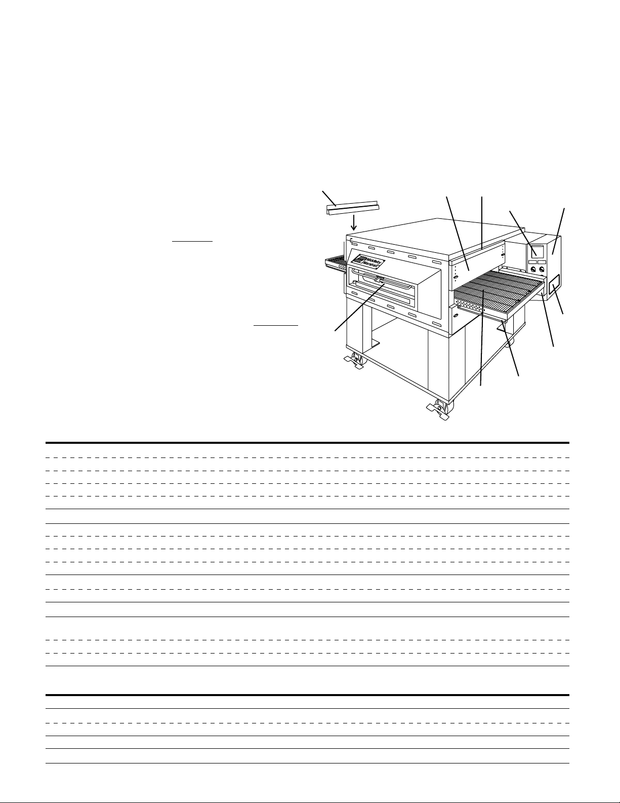
II. OVEN COMPONENTS - see Figure 1-1.
A. Window: Allows the user to see and access food products
inside the baking chamber.
B. Conveyor End Stop : Prevents food products from falling
off the end of the moving conveyor.
C. Eyebrows: Can be adjusted to various heights to prevent
heat loss into the environment.
D. End Plugs: Allow access to the oven's interior.
E. Control Panel: Location of the operating controls for the
oven. Refer to Section 3,
F. Machinery Compartment and Control Compartment
Doors: Allow access to the oven's interior components.
One door is located at each end of the oven. No userservicable parts are located inside the machinery compartment or control compartment.
G. Serial Plate: Provides specifications for the oven that affect
installation and operation. Refer to Section 2, Installation,
for details.
H. Conveyor Drive Motor: Moves the conveyor.
I. Crumb Pans: Catch crumbs and other material that drop
through the conveyor belt. One crumb pan is located
underneath each end of the conveyor.
Operation, for details.
J. Conveyor: Moves the food product through the oven.
Not Shown:
K. Gas Burner: Heats air, which is then projected to the air
fingers by the blowers.
L. Blowers: Fans that project hot air from the gas burner to
the air fingers.
M. Air Fingers: Project streams of hot air onto the food
product.
Fig. 1-1 - Oven Components
B
C
D
E
A
H
I
J
F
G
III. OVEN SPECIFICATIONS
Table 1-1: Dimensions
Overall Height:
Overall Depth:
Overall Length:
Baking Chamber Length
Conveyor Width:
Conveyor Length
Recommended Minimum Clearances:
Rear of oven to wall 3" (76mm)
Control end of conveyor to wall 1" (25.4mm)
Non-control end of oven to wall 1" (25.4mm)
Table 1-2: General specifications (per oven cavity)
Weight
Rated Heat Input:
Maximum Operating Temperature
Warmup Time
single oven with 17-1/2" (446mm) legs 43-1/2" (1105mm)
double oven with standard 17-1/2" (446mm) legs 63" (1600mm)
double oven with optional 20-1/2" (521mm) legs 66" (1676mm)
double oven with optional 25-1/2" (648mm) legs 71" (1803mm)
triple oven with 6" (152mm) legs 71" (1803mm)
46" (1168mm)
with standard 60"/1524mm conveyor 61" (1549mm)
with optional 56"/1422mm conveyor 57" (1447mm)
with optional 76"/1930mm conveyor 77" (1956mm)
36" (914mm)
Single Belt 20" (508mm)
Split Belt 2 x 9-1/2" (241mm)
56" (1422mm) or 60" (1524mm) or 76" (1930mm)
400 lbs. (182kg)
Natural gas ovens 70,000 BTU (17,638 kcal, 20.51 kW/hr.)
Propane ovens 70,000 BTU (17,638 kcal, 20.51 kW/hr.)
550°F (288°C)
4
25 minutes
Page 5

SECTION 1 - DESCRIPTION
Table 1-3: Electrical specifications for gas ovens (per oven cavity)
Main Blower Control Current
Voltage Circuit Voltage Phase Freq. Draw Poles Wires
208/240V
* The current draw shown above is an average value for normal operation. The initial amperage draw on oven startup may exceed the listed
value.
120V conv. speed control
& drive motor; all others
as per line (208/240V)
1 Ph 50/60 Hz 6A * 2 Pole 3 Wire (2 hot, 1 gnd)
Table 1-4: Gas orifice and pressure specifications (per oven cavity) - Domestic and standard export ovens
Gas Type Main Orifice I.D. Bypass Orifice I.D. Supply (Inlet) Pressure Pressure
Natural 0.0935” (2.3749mm, #42 drill) 0.0810” (2.0574mm, #46 drill) 6-12” W.C. (14.9-29.9mbar) * 4.0” W.C. (9.93mbar)
Propane 0.081” (2.0574mm, #46 drill) 0.052” (1.3208mm, #55 drill) 11-14” W.C. (27.4-34.9mbar) * 10.5” W.C. (26.15mbar)
*
The gas supply pressures and orifice sizes shown are for ovens installed in North America. The required gas supply pressures and orifice
sizes of ovens installed in other locations are dependent on the local gas type and on all applicable local codes.
Orifice (Manifold)
Table 1-5: Gas orifice and pressure specifications (per oven cavity) - CE ovens
Supply (Inlet) Pressure
Gas Orifice DK,FI NL DE BE,FR FI,DE,NL ES,UK (Manifold) Heat
Main UK,CH,IT,AT, SE,CH,AT,DK, BE,IE,IT,PT, Orifice Rated
Type dia.
G20 2.3749 20 -- 20 20 -- -- 11.21 22.36
mm mbar mbar mbar mbar kW-hr.
G25 2.3749 -- 25 - - -- -- -- 16.19 22.36
mm mbar mbar kW-hr.
G30 1.3970 -- -- -- -- 29 or 50 28-30, 37 26.2 22.59
mm mbar or 50 mbar mbar kW-hr.
IT,PT,ES,SE,
I
2H
I
2L
I
2E
I
2E+
I
3B/P
I
3+
Pressure Input
ENGLISH
IMPORTANT
Additional electrical information is provided on the oven's serial plate, and on the wiring diagram inside the machinery
compartment.
5
Page 6
WARNING - For gas ovens, after any conversions, readjustments, or service work on the oven:
ENGLISH
The oven must be installed on an even (level) non-flammable flooring and any adjacent walls must
be non-flammable. Recommended minimum clearances are specified in the
Do not obstruct the flow of combustion and ventilation air to and from your oven. There must be no
obstructions around or underneath the oven. Constructional changes to the area where the oven is
SECTION 2 - INSTALLATION
• Perform a gas leak test.
• Test for correct air supply.
• Test for proper combustion and gas supply.
• Check that the ventilation system is in operation.
WARNING
Keep the appliance area free and clear of combustibles.
WARNING
Description
this Manual.
WARNING
installed shall not affect the air supply to the oven.
CAUTION
For additional installation information, contact your local Authorized Service Agent.
section of
NOTE
There must be adequate clearance between the oven and combustible construction. Clearance
must also be provided for servicing and for proper operation.
NOTE
An electrical wiring diagram for the oven is located inside the machinery compartment.
NOTE
All aspects of the oven installation, including placement, utility connections, and ventilation requirements,
must conform with any applicable local, national, or international codes. These codes supersede the
requirements and guidelines provided in this manual.
NOTE
In the USA, the oven installation must conform with local codes. In the absence of local codes, gas oven
installations must conform with the National Fuel Gas Code, ANSI Z223.1. Installed ovens must be
electrically grounded in accordance with local codes, or in the absence of local codes, with the National
Electrical Code (NEC), or ANSI/NFPA70.
NOTE
In Canada, the oven installation must conform with local codes. In the absence of local codes, gas oven
installations must conform with the Natural Gas Installation Code, CAN/CGA-B149.1, or the Propane Gas
Installation Code, CAN/CGA-B149.2, as applicable. Installed ovens must be electrically grounded in
accordance with local codes, or in the absence of local codes, with the Canadian Electrical Code CSA C22.2.
NOTE
In Australia, the oven installation must conform with any requirements of the appropriate statutory authority.
Gas oven installtions must conform with AGA Codes AG311 and AG601.
NOTE
In CE countries, all aspects of the gas supply connection must comply with current IEC/CEE requirements and
with all applicable local, national, and international codes. In addition, four casters are provided to allow the oven
to be more easily moved to the installation location. These casters are intended to simplify pre-installation
movement only, and are NOT suitable for use as part of a CE oven installation. During the installation procedure,
the casters MUST be removed, so that the oven can be supported by the supplied 152mm adjustable legs.
6
Page 7
SECTION 2 - INSTALLATION
2
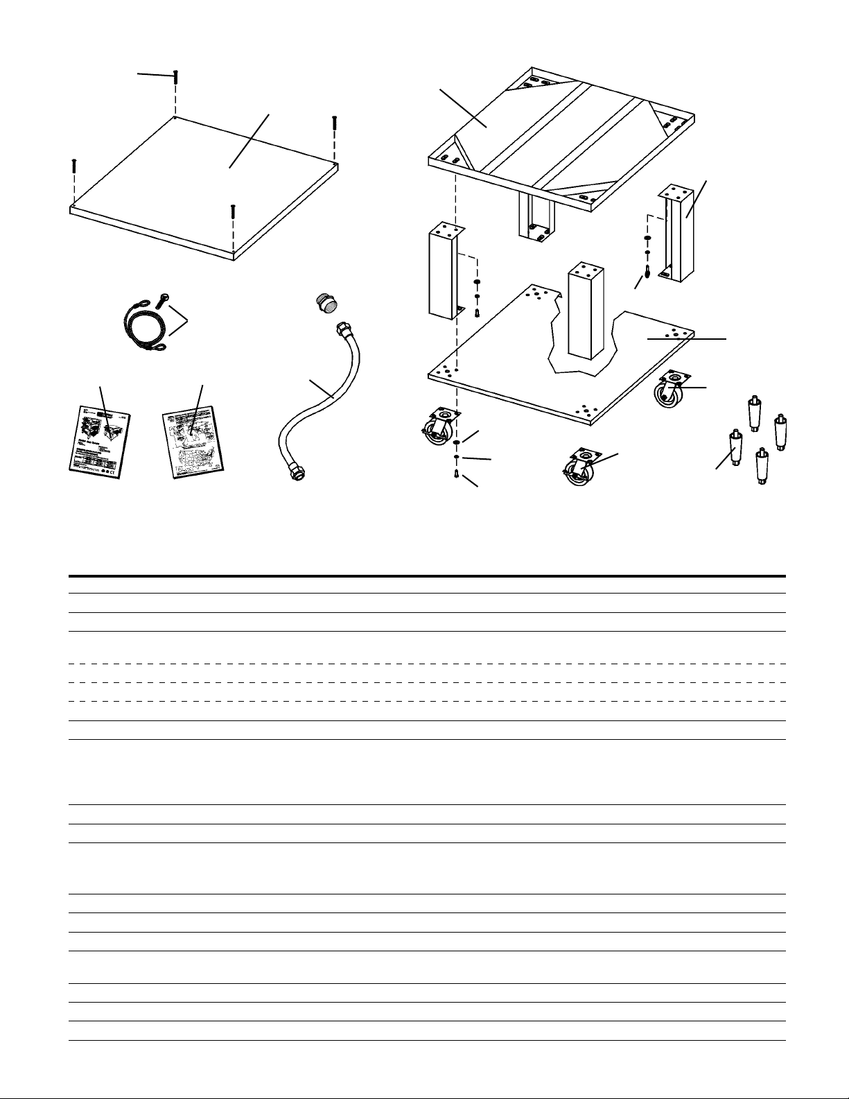
Figure 2-1 - Installation Kit
3
1
4a, 4b, 4c, 4d
ENGLISH
8
12
16
14
15
13
6
11
10
5
7
9
I. INSTALLATION KIT - see Figure 2-1
Qty. Qty. Qty. Inc. with Inc. with
Single Double Triple domestic CE
Item Oven Oven Oven Part No. ovens? ovens? Description
1 1 1 1 48605 Yes Yes Top panel
2 4 4 4 3A80A8801 Yes Yes Screw, pan head #10 x 2″
3 1 1 1 42893 Yes Yes Base pad
4a 4 4 -- 42890 Yes Yes 17-1/2″ (445mm) leg extension, for single and
4b -- 4 -- 45360 Yes Yes 20-1/2″ (521mm) leg extension, optional
4c -- 4 -- 45329 Yes Yes 25-1/2″ (648mm) leg extension, optional
4d -- -- 4 44799 Yes Yes 6″ (152mm) leg extension, for triple ovens
5 2 2 2 22290-0009 Yes No Caster, with flat plate and brake
6 A/R A/R A/R 22290-0010 Yes Yes Caster, with flat plate (no brake)
NOTE:
ovens include 4 non-braking casters (Item 6) SOLELY for the purpose of moving the oven to the installation location. Casters are
NOT suitable for use as part of CE oven installations. Refer to the notice on the preceding page.
NOTE:
that acts as an anchor for the restraint cable (Item 12). CE ovens are mounted on legs (Item 7) and do not use a restraint cable.
Domestic and standard export ovens include 2 braking casters (item 5) and 2 non-braking casters (Item 6). CE-approved
7 4 4 4 22450-0028 No Yes Leg, adjustable, 6″ (152mm)
8 1 1 1 21392-0004 Yes No Eyebolt, 3/4″
9 A/R A/R A/R 220373 Yes Yes Hex bolt, 3/8″-16 x 1″
CE-approved ovens include 32 hex bolts. Domestic and standard export ovens include 31 hex bolts and one eyebolt (item 8)
10 32 32 32 21416-0001 Yes Yes Flat washer, 3/8″
11 32 32 32 21422-0001 Yes Yes Lockwasher, 3/8″
12 1 1 1 22450-0228 Yes No Restraint cable assembly
13 1 2 3 22361-0001 Yes No Gas hose,
14 1 1 1 50236 Yes Yes
15 1 1 1 1002040 Yes Yes
16 1 1 -- 46393 Yes Yes Lower shelf
7
double ovens
3/4″ to 1/2″ Gas hose reducer
included with gas hose.
Owner's Operating and Installation Manual
Authorized Service Agency Listing
Page 8
SECTION 2 - INSTALLATION
II. VENTILATION SYSTEM
IMPORTANT
ENGLISH
Where national or local codes require the
installation of fire suppression equip-
ment or other supplementary equipment,
DO NOT mount the equipment directly to
the oven.
MOUNTING SUCH EQUIPMENT ON
THE OVEN MAY:
• VOID AGENCY CERTIFICATIONS
• RESTRICT SERVICE ACCESS
• LEAD TO INCREASED SERVICE EXPENSES FOR THE OWNER
A. Requirements
CAUTION
Gas oven installations REQUIRE a mechanically driven
ventilation system with electrical exhaust air sensing control.
A mechanically driven ventilation system is STRONGLY
RECOMMENDED for electric oven installations.
PROPER VENTILATION OF THE OVEN IS THE
RESPONSIBILITY OF THE OWNER.
B. Recommendations
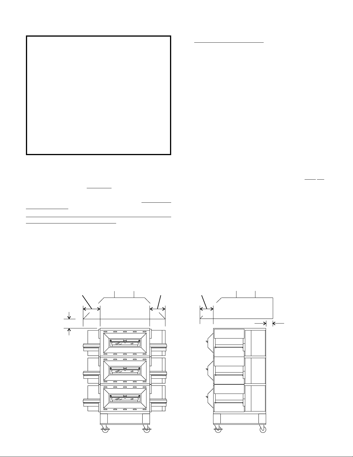
NOTE THAT THE HOOD DIMENSIONS SHOWN IN FIGURE 22 ARE RECOMMENDATIONS ONLY. LOCAL, NATIONAL AND
INTERNATIONAL CODES MUST BE FOLLOWED WHEN
INSTALLING THE VENTILATION SYSTEM. ANY APPLICABLE
CODES SUPERSEDE THE RECOMMENDATIONS SHOWN IN
THIS MANUAL.
The rate of air flow exhausted through the ventilation system
may vary depending on the oven configuration and hood design.
Consult the hood manufacturer or ventilation engineer for these
specifications.
To avoid a negative pressure condition in the kitchen area,
return air must be brought back to replenish the air that was
exhausted. A negative pressure in the kitchen can cause heatrelated problems to the oven components as if there were no
ventilation at all. The best method of supplying return air is
through the heating, ventilation and air conditioning (HVAC)
system. Through the HVAC system, the air can be temperaturecontrolled for summer and winter. Return air can also be
brought in directly from outside the building, but detrimental
effects can result from extreme seasonal hot and cold
temperatures from the outdoors.
NOTE: Return air from the mechanically driven system must not
blow at the opening of the baking chamber. Poor oven baking
performance will result.
C. Other ventilation concerns
• Special locations, conditions, or problems may require the
services of a ventilation engineer or specialist.
• Inadequate ventilation can inhibit oven performance.
• It is recommended that the ventilation system and duct
work be checked at prevailing intervals as specified by the
hood manufacturer and/or HVAC engineer or specialist.
12" (305mm)
minimum
2" (51mm)
minimum
Fig. 2-2 - Ventilation System
12" (305mm)
minimum
8" (203mm)
minimum
8
1" (25mm)
minimum
Page 9
III. ASSEMBLY
A. Top Panel and Base Pad Assembly
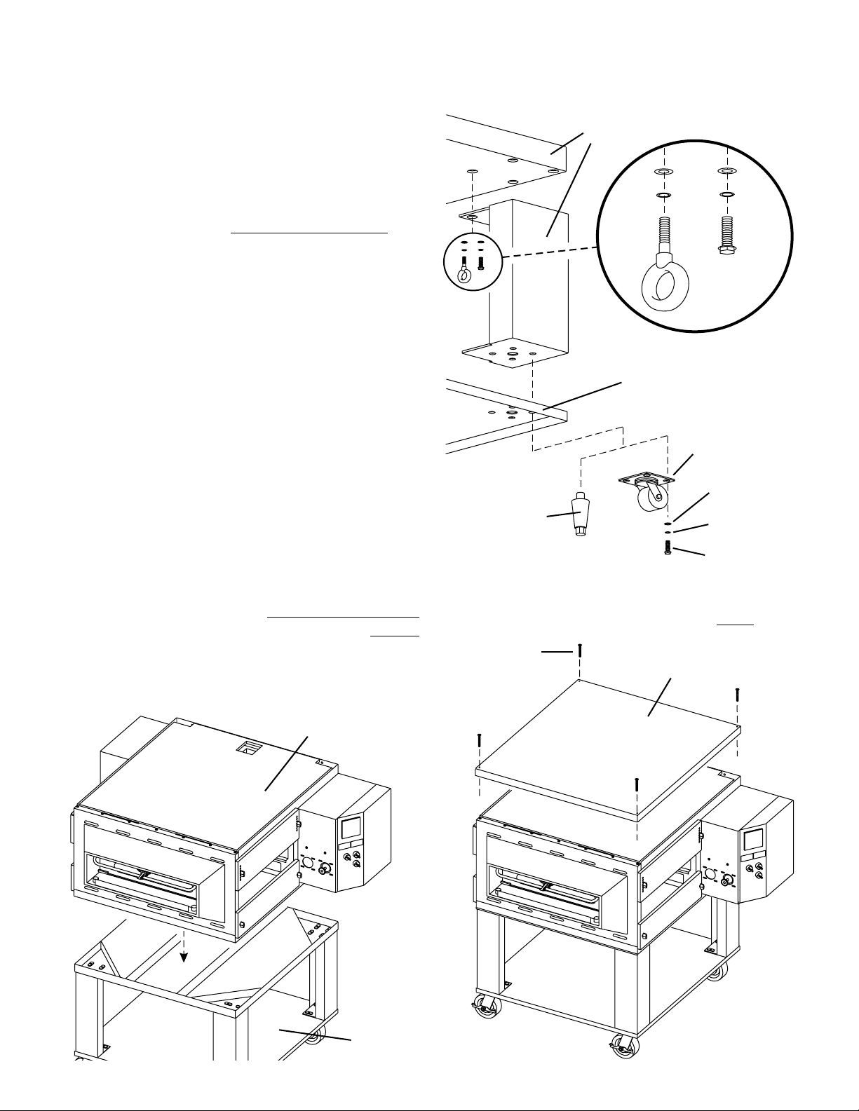
1. Install the four leg extensions onto the base pad using the
3/8"-16x1" screws, 3/8" flat washers, and 3/8" lockwashers
supplied in the Base Pad Kit. See Figure 2-3. Check that
the finished sides of each leg extension face OUTWARDS.
For domestic and standard export ovens:
One rear leg should be attached using three 3/8"-16 x 1"
screws and the 3/4" eyebolt, as shown in Figure 2-3. This
eyebolt acts as the anchor point for the restraint cable
assembly (see Part C,
2. If your oven is equipped with the lower shelf, position it in
place as shown in Figure 2-3. Check that the lip on the shelf
faces DOWN. Seal joint between leg and shelf with NSF
listed silicone.
3.
For domestic and standard export ovens:
Install one caster onto each leg extension, as shown in
Figure 2-4. Use the 3/8"-16x1" screws, 3/8" flat washers,
and 3/8" lockwashers supplied in the Installation Kit. The
locking casters should be installed at the FRONT of the
oven. The non-locking casters should be installed at the
REAR of the oven.
For CE export ovens:
The Installation Kit includes four casters AND four 152mm
adjustable legs. The casters are provided to allow the oven
to be more easily moved to the installation location, and are
NOT suitable for use as part of the oven installation. Refer
to the notice at the beginning of this Section.
After the oven is at the installation location, install one
152mm adjustable leg into the center hole on the bottom
of each leg extension, as shown in Figure 2-4.
4. Install the lower oven cavity onto the base pad. See Fig. 2-4.
5. For single ovens ONLY, install the top panel using the
screws included in the base pad kit, as shown in Figure 2-
5. Then, skip ahead to Part C,
For double or triple ovens, continue on to Part B,
Note that the top panel should NOT be installed for double
and triple ovens until after stacking the oven cavities.
Restraint Cable Installation).
Restraint Cable Installation.
Stacking.
SECTION 2 - INSTALLATION
Figure 2-3 - Leg extension and casters installation
Finished sides of
leg extension
face corner of
base pad
3/8" flat
washer
3/8" lock
washer
CE ovens
do not use
the
eyebolt.
Lower
shelf
Non-locking casters -
CE-approved
ovens:
152mm adjustable
leg MUST be used
for installation
3/8"-16 x 1"
hex screw
3/4" eyebolt
(inside corner
of one rear leg
extension
only)
Domestic and
standard export
ovens:
Locking casters -
FRONT of oven
REAR of oven
3/8" flat
washer
3/8" lock
washer
3/8"-16 x 1"
hex screw
Figure 2-5 - Top panel installation
NOTE:
DO NOT install top panel onto double or triple ovens
until AFTER stacking the oven cavities. See Part B, Stacking.
#10 x 2"
screws
Top
panel
ENGLISH
Figure 2-4 - Base pad installation
Bottom oven
cavity
Assembled
base pad
9
Page 10
SECTION 2 - INSTALLATION
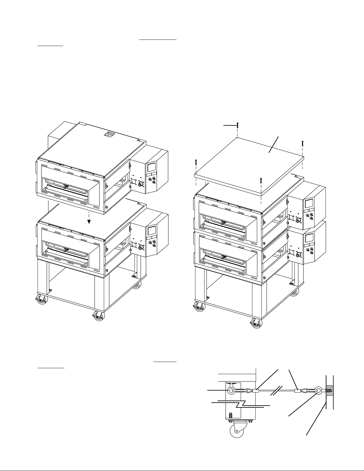
B. Stacking
For single ovens, skip ahead to Part C, Restraint Cable
Installation.
IMPORTANT
Middleby Marshall STRONGLY RECOMMENDS that PS536GS
ENGLISH
oven cavities be stacked using the following:
• PS500 Series Stacking Lift Kit, P/N 30580
• PS536 Stacking Hardware Kit, P/N 46494
Contact your Middleby Marshall Authorized Service Agent for
complete stacking instructions.
1. Stack an oven cavity on top of the lower oven. Check the
following:
• All four sides of the lower lip (on the bottom edge of the
oven cavity) overlap the top of the lower oven.
• The oven is level.
• The oven is firmly seated.
See Figure 2-6.
2. For triple ovens, repeat Step 1 to install the top oven cavity.
3. Install the top panel using the screws included in the base pad
kit, as shown in Figure 2-7.
Figure 2-6 - Stacking
Figure 2-7 - Top panel installation
#10 x 2"
screws
Top
panel
C. Restraint Cable Installation
For CE-approved ovens,
skip ahead to Part D, Conveyor
Installation.
For domestic and standard export ovens,
continue with this
Section to install the restraint cable.
Because domestic and standard export ovens are
equipped with casters, a restraint cable assembly must be
installed to limit the movement of the appliance without
depending on the connector and the quick disconnect
device or its associated piping. One end of the cable is
anchored to the eyebolt on one of the rear leg extensions,
while the other is anchored to the wall. See Figure 2-8.
After connecting the restraint cable, move the oven to its
final location. Then, lock the two front casters.
Figure 2-8 - Installing the Restraint Cable
Restraint cable
assembly
3/8"-16 x 1"
eyebolt on
rear leg
extension
3/4” (19mm)
eyebolt
Wall of
structure
10
Page 11
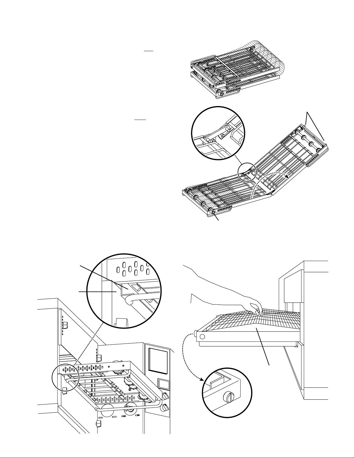
D. Conveyor Installation
1. Unfold the conveyor as shown in Figure 2-9. Then, begin
to slide the conveyor into the end of the oven. The conveyor
can only be installed from the end of the oven
with the drive
motor.
2. Continue moving the conveyor into the oven until the frame
protrudes equally from each end of the oven. Check that the
crumb tray supports located on the underside of the conveyor frame rest firmly against the lower end plugs, as
shown in Figure 2-10.
3. When the conveyor is positioned properly, check for freedom of movement of the conveyor belt by pulling it for about
2-3 feet (0.6-1.0m) with your fingers. The drive and idler
shafts must rotate smoothly, and the belt
must move freely
without rubbing on the inside of the oven.
4. Check the tension of the conveyor belt as shown in Figure
2-11. The belt should lift about 1" (25mm). DO NOT
OVERTIGHTEN THE CONVEYOR BELT.
NOTE:
If necessary, the belt tension can be adjusted by turning the
conveyor adjustment screws, located at the idler (noncontrol) end of the conveyor. See Figure 2-11.
SECTION 2 - INSTALLATION
Figure 2-9 - Conveyor installation
Folded
frame
Idler end (with
belt tension
adjustment
screws)
ENGLISH
Conveyor
placed in
oven
Drive end (with
drive sprocket)
Figure 2-10 - Conveyor placement
Figure 2-11 - Conveyor belt tension
Crumb tray
support
bracket
End plug
1" (25mm)
vertical
deflection
11
Adjustment
screws (2) on
idler end of
conveyor
Page 12
SECTION 2 - INSTALLATION
5. If it is necessary to add or remove conveyor links to achieve
the correct tension, OR if it is necessary to reverse the
conveyor belt for correct orientation, the belt will need to be
removed from the conveyor frame. If this is necessary,
perform the following procedure:
ENGLISH
• Remove the conveyor assembly from the oven and
place it flat on the floor.
• Remove the master links using long-nose pliers.
Then, roll up the belt along the length of the conveyor
frame.
• Add or remove belt links as necessary to achieve the
correct belt tension.
• Replace the belt on the conveyor frame. Check that the
conveyor belt links are oriented as shown in Figure 212, and that the smooth side of the conveyor belt faces
UP.
• Connect the inside master links. Check that the links
are oriented as shown in Figure 2-12.
• Connect the outside master links. Note that the
outside master links each have an open hook on one
side. This hook aligns with the hooks along the sides
of the other conveyor links. See Figure 2-12.
• Replace the conveyor into the oven.
E. Final Assembly
6. Install the drive chain between the conveyor drive sprocket
and the motor sprocket. To install the chain, it will be
necessary to lift the drive end of the conveyor slightly.
7. Install the conveyor chain cover as shown in Figure 2-13.
Check that the chain cover does not bind on the conveyor
sprocket or drive shaft.
8. Install the crumb trays as shown in Figure 2-13.
9. Press the end stop down over the edge of the conveyor
frame at the exit end of the oven, as shown in Figure 2-13.
Figure 2-12 - Conveyor and master link orientation
Direction
of travel
Incorrect
master link
position
CORRECT
master link
position
Press conveyor end stop
down over edge of
conveyor frame
Figure 2-13 - Final assembly
Hang chain cover on
screws in control
compartment wall
12
Place inside edge
of tray on retainer
bracket
Swing outside
edge of tray up
and into place
Page 13
IV. ELECTRICAL SUPPLY
WARNING
Authorized supplier personnel normally accomplish
the connections for the ventilation system, electric supply,
and gas supply, as arranged by the customer. Following
these connections, the factory-authorized installer can
perform the initial startup of the oven.
NOTE: The electric supply installation must satisfy the
requirements of the appropriate statutory authority, such as the
National Electrical Code (NEC), ANSI/NFPA70, (U.S.A.); the
Canadian Electrical Code, CSA C22.2; the Australian Code,
AG601; current IEC/CEE requirements (CE countries); or other
applicable regulations.
NOTE: All aspects of the electrical supply connection must
comply with all applicable local, national, and international
code requirements.
Check the oven serial plate before making any electric supply
connections. Electric supply connections must agree with data
on the oven serial plate. The location of the serial plate is shown
in Figure 1-1 (in Section 1, Description).
A fused disconnect switch or a main circuit breaker (customer
furnished) MUST be installed in the electric supply line for each
oven cavity. It is recommended that this circuit breaker/disconnect
have lockout/tagout capability. For CE installations, the circuit
breaker/disconnect must have a minimum of 3mm contact
separation breaking all poles of the supply.
The supply conductors must comply with all applicable local,
national and international codes. Supply conductors must be
insulated copper wiring, #18 AWG (American Wire Gauge) or
equivalent. Additional wiring information is shown on the wiring
diagrams in Section 5, Electrical Wiring Diagrams and inside
the machinery compartment of the oven.
SECTION 2 - INSTALLATION
The oven requires a ground connection to the oven ground
screw located in the electrical junction box. (The box is shown
in Figure 2-14.) The ground connection must comply with all
applicable local, national, and international codes. If necessary,
have the electrician supply the ground wire.
Do NOT use the
wiring conduit or other piping for ground connections!
A. Additional Information - Gas Ovens
All electric supply connections are made via the electrical
junction box on the rear of the oven, shown in Figure 2-14. The
power lines then connect to the oven circuits through safety
switches that interrupt electric power to the oven:
• When the Control Compartment Access Panel is opened;
• When the Machinery Compartment Access Panel is opened,
OR
• When the rear panel is removed.
B. Connection
Refer to the wiring diagram inside the machinery compartment,
or in Section 5 of this Manual, to determine the correct
connections for the electrical supply lines. Connect the supply
as indicated on the wiring diagram.
If required by local, national or international codes, connect an
equipotential ground wire to the lug next to the symbol
(shown in Figure 2-14). The equipotential ground connection
must meet all applicable national and local code requirements.
ENGLISH
33mm cutout for
electric utility
connection
Equipotential
ground lug
Figure 2-14 - Utility connection locations
1/2" NPT pipe for gas
utility connection
(fitted with 3/4" adapter
for use with supplied
3/4" dia. gas hose)
Electrical
Junction Box
13
Page 14
SECTION 2 - INSTALLATION
V. GAS SUPPLY
CAUTION
DURING PRESSURE TESTING NOTE THE FOLLOWING:
1. The oven and its individual shutoff valve must be discon-
ENGLISH
nected from the gas supply piping system during any
pressure testing of that system at test pressure in excess
of 1/2 psi (3.45 kPa).
2. The oven must be isolated from the gas supply piping
system by closing its individual manual shutoff valve
during any pressure testing of the gas supply piping
system at test pressure equal to or less than 1/2 psi (3.45
kPa).
3. If incoming pressure is over 14" W.C. (35mbar), a
separate regulator MUST be installed in the line BEFORE
the individual shutoff valve for the oven.
WARNING:
lator during initial turn- on of gas, it is
To prevent damage to the control valve regu-
very important to
open the manual shutoff valve very slowly.
After the initial gas turn-on, the manual shutoff valve must
remain open except during pressure testing as outlined
in the above steps or when necessary during service
maintenance.
A. Gas Utility Rough-In Recommendations
The following gas system specifications are STRONGLY
RECOMMENDED. Deviating from these recommendations
may affect the baking performance of the oven.
Gas Meter -
650 cfh (307l/min) meter
Gas Line
• DEDICATED LINE from the gas meter to the oven
• 2" (50.8mm) pipe for natural gas
• 1-1/2" (38.1mm) pipe for propane
• Maximum length: 200' (61m). Each 90° elbow equals 7'
(2.13m) of pipe.
B. Gas Conversion
Ovens are shipped from the factory configured for use with
natural gas. If permitted by local, national and international
codes, the oven may be converted to propane gas operation
using a Gas Conversion Kit that is supplied with the oven. Gas
orifice sizes supplied with the Kit match those shown in Tables
1-4 and 1-5 in the Description section of this Manual.
Where permitted by local and national codes, it is possible to
convert ovens from natural to propane gas, or from propane to
natural gas, after the oven has been installed. Gas Conversion
Kits are available from Middleby Marshall for this purpose.
C. Connection
WARNING
Some procedures in this section may require conver-
sions, readjustments, or service on the oven's gas
system. Before performing these procedures, check that the
main gas supply valve and the circuit breaker/fused disconnect are in the OFF ("O") position. After completing these
procedures, perform a gas leak test before operating the
oven.
CAUTION
The terms of the oven's warranty require all start-ups, conversions and service work to be performed by a Middleby Marshall
Authorized Service Agent. The installation, start-up and changes
required when changing from one gas type to another can be
performed ONLY by a certified professional.
NOTE:
Certain safety code requirements exist for the installation
of gas ovens; refer to the beginning of Section 2 for a list of the
installation standards. In addition:
• In the USA,
the installation must conform with local codes,
or in the absence of local codes, with the National Fuel Gas
Code, ANSI Z223.1.
• In Canada,
the installation must conform with local codes,
or in the absence of local codes, with the Natural Gas
Installation Code, CAN/CGA-B 149.1, or the Propane
Installation Code, CAN/CGA-B 149.2, as applicable.
• In Australia,
the installation must conform with AGA Codes
AG311 and AG601, and with any requirements of the
appropriate statutory authority.
• In CE countries,
the gas supply connection should be
according to EN-203 (gas appliance directive) and to
applicable ISO 228-1 or ISO 7-1 recommendations. All
aspects of the gas supply connection must comply with
current IEC/CEE requirements and with all applicable
local, national, and international codes.
• For all ovens equipped with casters,
the gas line connection
shall be made with:
- A connector that complies with the Standard for
Connectors for Movable Gas Appliances, ANSI Z21.69
(in USA), or Connectors for Movable Gas Appliances,
CAN/CGA-6.16 (in Canada).
Check the oven’s gas supply requirements to determine the
type of gas to be used with the oven. If the gas type required does
NOT match the local supply:
• For North American installations,
a conversion kit is
supplied with the oven to allow operation using propane
gas. Refer to Part B,
Gas Conversion, in this section.
• For CE ovens, directions for converting the oven for use with
other gases are described in Part D.1, Preparation for Use
with Various Gases, in this section.
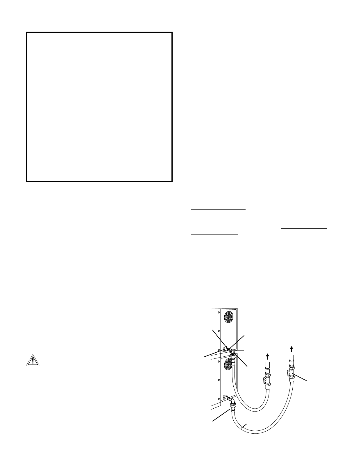
If the installation will use the supplied gas hose, be sure that
the 1/2" to 3/4" gas line fitting is attached. Refer to the instructions
in the gas hose package. One gas line connection method is
shown in Figure 2-15; however, compliance with the applicable
standards and regulations is mandatory.
Inlet and regulated gas pressures can be measured using a
“U” tube manometer at the tap locations shown in Figures 2-15
and 2-16.
Figure 2-15 - Flexible Gas Hose Installation
1/2" gas
pipe nipple
1/2" gas line
tee with
pressure tap
Quick-
disconnect
device
14
3/4"-1/2"
gas pipe
reducer
3/4" gas
pipe nipple
90°
Elbow
Flexible
Gas Hose
To Gas
Supply
Pipe
Full-Flow
Individual gas
connection for
each oven
cavity
Gas
Shutoff
Valve
Page 15

1. Checking the Gas Supply (Inlet) Pressure
a. With the main gas supply valve closed and the circuit
breaker/fused disconnect in the OFF ("O") position, open
the inlet pressure tap shown in Figure 2-16 and attach a
manometer to the tap.
b. Depress the safety switches to allow the oven to operate.
c. Open the main gas supply valve. Switch the circuit breaker/
fused disconnect to the ON ("I") position.
d. Start the oven according the directions in the
Operation
section of this Manual. Adjust the temperature controller to
the maximum setting (316°C).
e. Measure the supply (inlet) pressure.
f. Switch the oven off. Close the main gas supply valve, and
switch the circuit breaker/fused disconnect to the OFF ("O")
position. Remove the manometer, and close the inlet tap.
g. Compare the measured supply (inlet) pressure to the
nominal pressures shown in Table 1-5 (in the
Description
section of this Manual).
If the supply pressure is lower or higher than the nominal
pressure, the reason should be investigated and the gas
supplier contacted.
For natural gas ovens, if the measured supply pressure is lower
than 0.247psi, or higher than 0.363psi, contact the gas supplier.
DO NOT OPERATE THE OVEN or adjust the oven controls.
2. Adjusting the Orifice (Manifold) Pressure and Heat Input
To use the orifice pressure method, you must know the specific
gas type and quality used. If using the orifice pressure method,
you should double-check the input using the volumetric method.
To use the volumetric method, you must know the heat value
(HuB) of the gas used. This information is available from your
gas supplier.
During these measurements, do not operate any other
appliances that use the same gas meter as the oven.
a. Orifice (Manifold) Pressure Method
1. With the main gas supply valve closed and the circuit
breaker/fused disconnect in the OFF ("O") position,
open the manifold pressure tap shown in Figure 2-16
and attach a manometer to the tap.
2. Remove the cap screw from the pressure adjustment
screw (governor) on the gas control valve.
3. Depress the safety switches to allow the oven to
operate.
4. Open the main gas supply valve. Switch the circuit
breaker/fused disconnect to the ON ("I") position.
5. Start the oven according the directions in the Operation
section of this Manual. Adjust the temperature controller
to the maximum setting (316°C).
6. Adjust the pressure adjustment screw as necessary
to match the correct pressure for the oven's specific
gas type. Refer to Table 1-5 in the Description section
of this Manual. Turning the adjustment screw clockwise
increases the flow, while turning it counterclockwise
reduces the flow.
7. Switch the oven off. Close the main gas supply valve,
and switch the circuit breaker/fused disconnect to the
OFF ("O") position. Remove the manometer, and
close the manifold pressure tap.
SECTION 2 - INSTALLATION
b. Volumetric Method
1. Determine the time of 0.1m
3
(100 liters) of gas usage
as follows.
Consumption (m
3
/hr.) =
NB (Rated input in kW)
HuB (Heat [Calorific] value
of gas in kW/m3)
Time (in minutes) of
0.1m3 of gas usage
=
6
Consumption
2. Check that the main gas supply valve and the circuit
breaker/fused disconnect are in the OFF ("O") position.
3. Remove the cap screw from the pressure adjustment
screw (governor) on the gas control valve.
4. Depress the safety switches to allow the oven to
operate.
5. Open the main gas supply valve. Switch the circuit
breaker/fused disconnect to the ON ("I") position.
6. Start the oven according the directions in the
section of this Manual. Adjust the temperature controller
to the maximum setting (316°C).
7. Adjust the pressure adjustment screw as necessary
to match the calculated volume using the time (in
minutes) of 0.1m3 of gas usage. Turning the
adjustment screw clockwise increases the flow, while
turning it counterclockwise reduces the flow.
8. Record the reading obtained from the gas meter and
calculate the obtained gas flow. Compare this value
to the information in Tables 1-4 and 1-5 in the
Description section of this Manual.
9. Switch the oven off. Close the main gas supply valve,
and switch the circuit breaker/fused disconnect to the
OFF ("O") position. Replace the cap screw onto the
gas control valve.
Figure 2-16 - Gas Control Valve
Manifold
pressure tap
(where regulated
gas pressure is
measured)
Pressure adjustment
screw (under cap)
15
ENGLISH
Operation
Page 16

ENGLISH
SECTION 3 - OPERATION
E
D
A
I. LOCATION AND DESCRIPTION OF CONTROLS
A.
B.
C.
D.
"BLOWER" Switch: Turns the blowers and
cooling fans on and off. The HEAT Switch has
no effect unless the BLOWER Switch is in the
“ON” position.
"HEAT" Switch: Allows the burner to activate.
Activation is determined by the settings on the
Digital Temperature Controller.
"CONVEYOR" Switch: Turns the conveyor drive
motor on and off.
Conveyor Speed Controller: Adjusts and displays the bake time. Single-belt ovens have one
controller. Split belt ovens have one controller
for each conveyor belt, labeled "FRONT" and
"BACK."
B
C
E.
Digital Temperature Controller: Continuously
monitors the oven temperature. Settings on the
Digital Temperture Controller control the activation of the burner. Keypad controls allow the
operator to select the cooking temperature and
monitor oven operation.
NOT SHOWN:
F. Machinery and Control Compartment Safety Switches:
Disconnect electrical power to the controls and blowers
when EITHER the machinery compartment door OR the
control compartment door is opened. The doors should
only be opened by authorized service personnel.
16
Page 17

II. NORMAL OPERATION - STEP-BY-STEP
A. DAILY STARTUP PROCEDURE
1. Check that the circuit breaker/fused disconnect is in the on
position. Check that the window is closed.
2. Turn the "BLOWER" ( )
switch to the “ON” ("I")
position.
3. Turn the "CONVEYOR"
(
) switch to the “ON”
("I") position.
SECTION 3 - OPERATION
7. Wait for the oven to heat to the setpoint temperature. Higher
setpoint temperatures will require a longer wait. The oven
can reach a temperature of 500°F (232°C) in approximately
5 minutes.
(Optional)
8.
perature (
the Actual Temperature
in the display, and wait
for the "ACTUAL TEMP"
light to turn on. This allows you to monitor the
oven temperature as it
rises to the setpoint.
9. Allow the oven to preheat for 10 minutes after it has reached
the set point temperature.
B. DAILY SHUTDOWN PROCEDURE
Press the Tem-
) key to show
wait
for
ENGLISH
4. If necessary, adjust the
conveyor speed setting
by pressing the
pushbuttons on the conveyor speed controller to
change the displayed
bake time.
5. Adjust the temperature
controller to a desired set
temperature, if necessary.
• Press the Set Point
and Unlock keys at
the same time. Wait
for the "SET PT" light
to turn on.
• Press the Up Arrow
and Down Arrow
Keys as necessary
to adjust the setpoint.
6. Turn the "HEAT" ( )
switch to the "ON" ("I")
position, and wait for the
"HEAT ON" light to turn
on.
or
+
or
or
wait
for
wait
for
1. Turn the "HEAT" (
"BLOWER" (
ches to the "OFF" ("O")
position. Note that the
blowers will remain in operation until the oven has
cooled to below 200°F
(93°C).
2. Make certain that there
are no products left on
the conveyor inside the
oven. Turn the "CONVEYOR" ( ) switch to
the "OFF" ("O") position.
3. Open the window to allow the oven to cool faster.
4. After the oven has cooled and the blowers have turned off,
switch the circuit breaker/fused disconnect to the off position.
) and
) swit-
+
IMPORTANT
On gas ovens, if the "HEAT ON" light will not illuminate, OR
if the oven does not heat, the gas burner may not have lit.
Turn the "HEAT" (
(
) switches to the "OFF" ("O") position. Wait for AT
LEAST FIVE MINUTES before restarting the oven. Then,
repeat the Daily Startup procedure.
), "BLOWER" ( ), and "CONVEYOR"
CAUTION
In case of power failure, turn all switches to the “OFF” ("O")
position, open the oven window, and remove the product.
After the power has been restored, perform the normal
startup procedure. IF THE OVEN WAS SWITCHED OFF
FOR LESS THAN 5 MINUTES, WAIT FOR AT LEAST FIVE
MINUTES BEFORE RESTARTING THE OVEN.
The burner will not operate and gas will not flow through
the burner without electric power. No attempt should be
made to operate the oven during a power failure.
17
Page 18

SECTION 3 - OPERATION
III. QUICK REFERENCE: DIGITAL TEMPERATURE CONTROLLER
ENGLISH
"SP LOCK"
Light
Lights when the
set point is locked
out from changes.
This setting can
only be changed by
service personnel.
OVERTEMP
Light
Lights when the oven
temperature is
greater than 650°F
(343°C). Refer to
Quick Reference:
Troubleshooting in
this section.
Display
Shows the Set Point
or the Actual Tem-
perature in degrees
Fahrenheit (F) or
Celsius (C).
"HEAT ON"
Light
Lights when the
burner is in
operation.
"SET PT"
(setpoint)
Light
Lights when the
set point is shown
in the display.
"ACTUAL
TEMP" Light
Lights when the
Actual Tempera-
ture is shown in
the display.
Temperature
Key
Press this key once
to view the Actual
Temperature in the
Display.
together with the Set
Point Key to allow the
changed. Changes
can only be made for
Unlock Key
Press this key
Set Point to be
60 seconds.
Up Arrow and Down
Arrow Keys
Press these keys to
adjust the Set Point up or
down. If the Set Point will
not change, refer to Set
Point Key and Unlock Key
in this section.
18
Service Key
Service use
only.
Set Point Key
Press this key
together with the
Unlock Key to allow
the Set Point to be
changed.
Changes can only be
made for 60 sec-
onds.
Page 19

SECTION 4 - MAINTENANCE
WARNING
Before ANY cleaning or servicing of the oven, perform the following procedure:
1. Switch off the oven and allow it to cool. Do NOT service the oven while it is warm.
2. Turn the full-flow gas safety valve to the off position.
3. Turn off the electric supply circuit breaker(s) and disconnect the electric supply to the oven.
4. If it is necessary to move a gas oven for cleaning or servicing, disconnect the gas supply before moving the oven.
When all cleaning and servicing is complete:
1. If the oven was moved for servicing, return the oven to its
original location.
2. Reconnect the gas supply.
3. Reconnect the electrical supply.
4. Turn on the full-flow gas safety valve. Test the gas line
connections for leaks using approved leak test substances or thick soap suds.
5. Turn on the electric supply circuit breaker(s).
6. Perform the normal startup procedure.
WARNING
Possibility of injury from moving parts and electrical shock exists in this oven. Switch off and lockout/tagout the electric
supply BEFORE beginning to disassemble, clean, or service any oven. Never disassemble or clean an oven with the
BLOWER ( ) switch or any other circuit of the oven switched on.
CAUTION
NEVER use a water hose or pressurized steam-cleaning equipment when cleaning this oven. To avoid saturating the oven
insulation, DO NOT use excessive amounts of water. DO NOT use a caustic oven cleaner, which can damage the bake
chamber surfaces.
NOTE
ANY replacement parts that require access to the interior of the oven may ONLY be replaced by a Middleby Marshall Authorized
Service Agent. It is also strongly recommended that the 3-Month Maintenance and 6-Month Maintenance procedures in this
section be performed ONLY by a Middleby Marshall Authorized Service Agent.
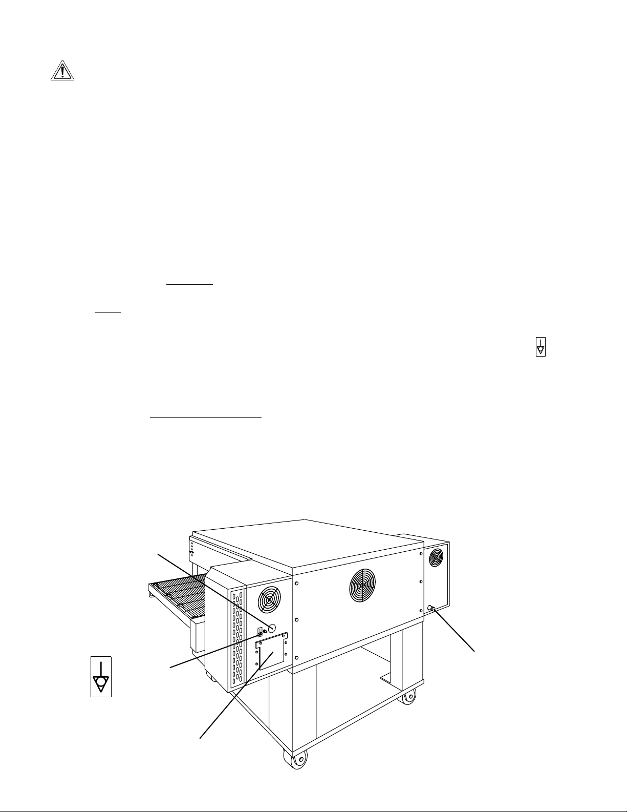
I. MAINTENANCE - DAILY
A. Check that the oven is cool and the power is disconnected,
as described in the warning at the beginning of this Section.
B. Clean ALL of the cooling fan grills and vent openings with a
stiff nylon brush. Refer to Figure 4-1 for the locations of the
grills and vents.
C. Clean the outside of the oven with a soft cloth and mild
detergent.
D. Check that ALL cooling fans are operating properly.
CAUTION
If a cooling fan is not operating correctly, it must be replaced
IMMEDIATELY. Operating the oven without adequate
cooling can seriously damage the oven's internal components.
E. Clean the conveyor belts with a stiff nylon brush. This is
more easily accomplished by allowing the conveyor to run
while you stand at the exit end of the conveyor. Then, brush
the crumbs off the conveyor as it moves.
F. Remove and clean the crumb trays. If necessary, refer to
Figure 2-13 (in Section 2, Installation) when replacing the
crumb trays into the oven.
G. Clean the window in place.
Vents on
front panel
of oven
Figure 4-1 -Cooling Vents and Grills
ENGLISH
Vents on rear
of control
compartment
19
door
Fan grills (2) on rear
of oven and control
compartment
Vent (1) on rear
of machinery
compartment
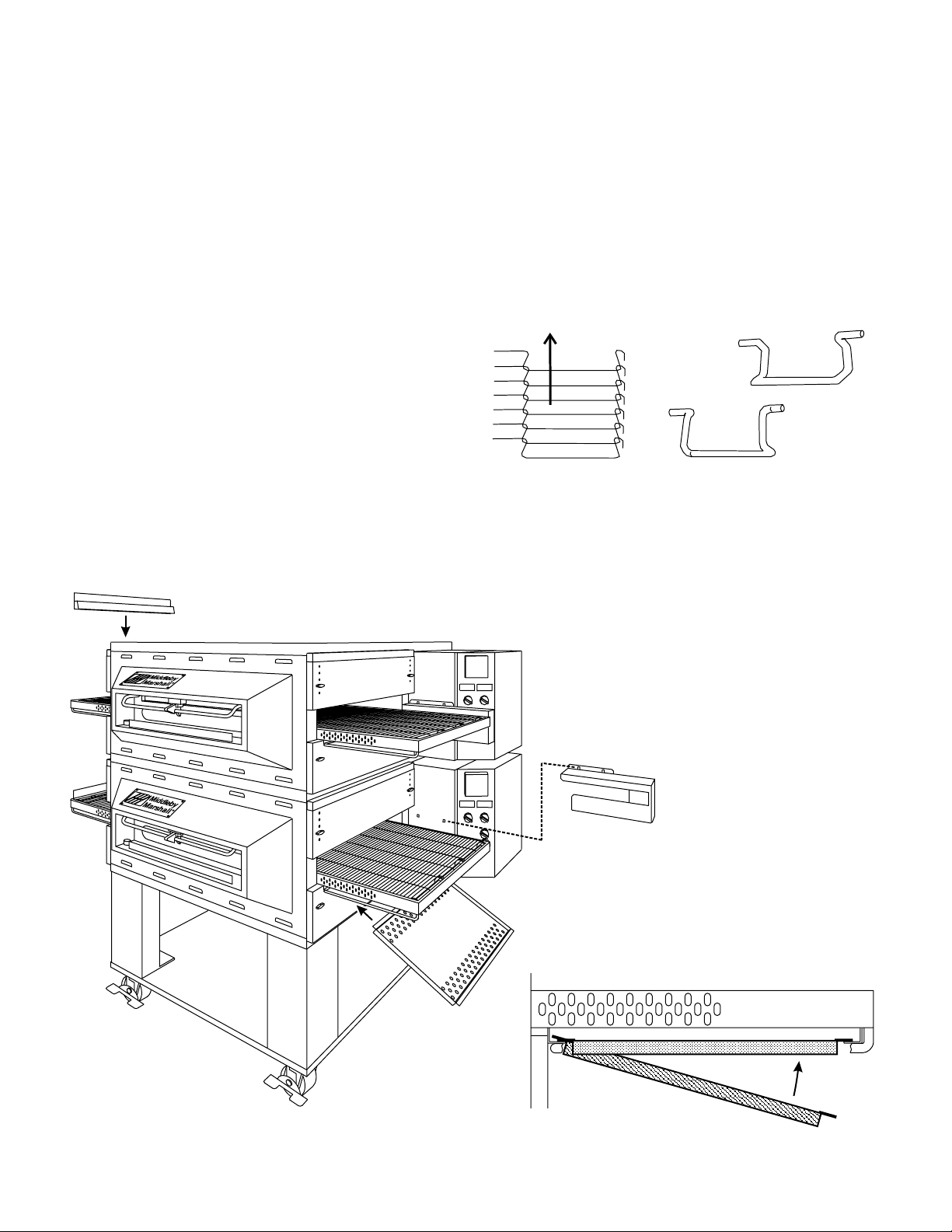
Page 20

II. MAINTENANCE - MONTHLY
A. Check that the oven is cool and the power is disconnected,
as described in the warning at the beginning of this Section.
B. Refer to Part D, Conveyor Installation, in the Installation
ENGLISH
section of this Manual. Then, remove the following components from the oven:
• Conveyor end stop
• Crumb trays
• Chain cover
• Drive chain
• End plugs
• Conveyor assembly
C. Slide the air fingers and blank plates out of the oven, as
shown in Figure 4-2. AS EACH FINGER OR PLATE IS
REMOVED, WRITE A "LOCATION CODE" ON IT WITH A
MARKER to make sure that it can be reinstalled correctly.
Example of markings:
(Top Row) T1 T2 T3 T4
(Bottom Row) B1 B2 B3 B4
D. Disassemble the air fingers. See Figure 4-3. AS EACH
FINGER IS DISASSEMBLED, WRITE THE "LOCATION
CODE" FOR THE FINGER ON ALL THREE OF ITS PIECES.
This will help you in correctly reassembling the air fingers.
CAUTION
Incorrect reassembly of the air fingers will change the
baking properties of the oven.
E. Clean the air finger components and the interior of the
baking chamber using a vacuum cleaner and a damp cloth.
Refer to the boxed warnings at the beginning of this Section
for cleaning precautions.
F. Reassemble the air fingers. Then, replace them in the
oven, using the "location code" as a guide.
G. Install the end plugs on the oven. Then, reinstall the
conveyor.
I. Reattach the drive chain. Replace the chain cover.
J. Check the tension of the conveyor belt as shown in Figure
2-11 (in Section 2, Installation). The belt should lift about
1" (25mm). If necessary, adjust the belt tension using the
procedure in Part D (Conveyor Installation) in the Installation section of this Manual.
K. Replace all components onto the oven.
SECTION 4 - MAINTENANCE
Figure 4-2 - Removing Air Fingers and Plates
Figure 4-3 - Disassembling the Air Fingers
Outer Plate
Inner plate
Manifold
III. MAINTENANCE - EVERY 3 MONTHS
A. Check that the oven is cool and the power is disconnected,
as described in the warning at the beginning of this Section.
B. Open the machinery compartment access panel. Vacuum
the inside of the compartment using a shop vacuum.
C. Tighten all electrical control terminal screws.
D. Split Belt Disassembly and Cleaning
1. Refer to Part D, Conveyor Installation, in the Installation section of this Manual. Then, remove the following
components from the oven:
• Conveyor end stop
• Crumb trays
• Chain cover
• Drive chains
• End plugs
• Conveyor assembly
20
Page 21

SECTION 4 - MAINTENANCE
2. Remove the master links from each conveyor belt.
Then, roll the belts up along the length of the conveyor
to remove them from the frame.
3. Remove the two conveyor adjustment screws from the
idler end of the conveyor frame, as shown in Figure 4-
4.
4. Remove the idler shaft assembly from the conveyor.
5. Pull apart the two sections of the idler shaft.
6. Clean the shafts thoroughly using a rag. Then, lubricate both the extended shaft and the interior of the
hollow shaft using a light food-grade lubricant. DO
NOT lubricate the shafts using WD40 or a similar
product. This can cause the shafts to wear rapidly.
7. Before reassembling the shafts into the conveyor
frame, check that they are oriented properly.
8. Reassemble the idler shaft into the conveyor.
sure that the bronze washer is in place between the
two sections of the shaft. See Figure 4-4.
9. Replace the conveyor adjustment screws as shown in
Figure 4-4. To allow the conveyor belt to be reinstalled
later, do not tighten the screws at this time.
10. Loosen the set screw on both of the conveyor drive
sprockets. Then, remove the sprockets from the shaft.
11. Check the conveyor configuration as follows:
• High-speed conveyors are equipped with large
flange bearings at both ends of the shaft, as
shown in Figure 4-5. For these conveyors, remove the two screws that hold each bearing to the
conveyor frame. With the screws removed, lift the
end of the shaft at the front of the oven, and pull the
entire assembly free of the conveyor frame.
• Standard conveyors are equipped with bronze
bushings mounted on spacers at both ends of the
shaft, as shown in Figure 4-5. For these conveyors, remove the two screws that hold the bracket
to the conveyor frame. With the screws removed,
lift the end of the shaft at the front of the oven, and
pull the entire assembly free of the conveyor
frame. The brackets will be removed along with
the drive shaft assembly.
12. Disassemble and lubricate the two sections of the
drive shaft as described for the idler shaft, above.
13. Before reassembling the shafts into the conveyor
frame, check that they are oriented properly.
14. Reassemble the drive shaft into the conveyor. Make
sure that the bronze washer is in place between the
two sections of the shaft. See Figure 4-6.
15. Replace the drive sprockets. Reassemble the belts
and master links onto the conveyor.
16. Reinstall the end plugs and conveyor onto the oven.
17. Reattach the drive chains. Replace the chain cover.
18 Check the tension of the conveyor belt as shown in
Figure 2-11 (in Section 2, Installation). The belt should
lift about 1" (25mm). If necessary, adjust the belt
tension by turning the conveyor adjustment screws.
19. Replace all components onto the oven.
Make
Flange bearing
(used with high-
speed conveyors)
21
Figure 4-4 - Disassembling the idler shaft
Disassemble,
lubricate shafts
Bronze
washer
Remove
adjustment
screws
Figure 4-5 - Drive shaft configurations
Bronze bushing with
spacer (used with
standard conveyors)
Figure 4-6 - Disassembling the drive shaft
Disassemble,
clean, and
lubricate shafts
Flange bearing
shown (used with
high-speed
conveyors)
remove drive
Remove 2 screws and nuts per
side to free bearings/brackets
clean, and
ENGLISH
Remove
idler
shaft
assembly
Loosen set
screws and
sprockets
Page 22

E. Blower Belt
1. Remove the six screws shown in Figure 4-7. Then,
remove the rear panel from the oven.
2. Check the blower belt for the proper 1/4" (6mm) deflection at the center, and for cracking or excessive wear.
ENGLISH
See Figure 4-7. Overtightening the belt will cause
premature bearing failure and possible vibrations. A
loose belt may also cause vibrations.
3. If necessary, adjust the tension of the belt by loosening
the four motor mounting bolts. Reposition the motor
as neccessary until the correct 1/4" (6mm) deflection
is reached, then tighten the bolts.
F. Lubricating the Blower Fan Bearings
1. Use a grease gun to lubricate the main blower fan
shaft bearings, as shown in Figure 4-7.
When lubricating the bearings:
• Use a high-quality NLGI #2, lithium soap grease with
petroleum oil, such as Middleby P/N 17110-0015.
• Add the grease slowly until a small bead of grease
is present at the seals.
AVOID OVERGREASING.
Excessive greasing may cause harm to the bearing.
2. Manually turn the blower shaft by pulling on the belt to
purge the grease. Wipe off any excess grease.
3. Replace the rear panel onto the oven.
IV. MAINTENANCE - EVERY 6 MONTHS
A. Check that the oven is cool and the power is disconnected, as
described in the warning at the beginning of this Section.
B. Check for excessive wear on the conveyor drive motor
brushes. The brushes should be replaced if they have
worn to less than 1/4" (6mm) in length. Be sure to replace
the brushes in exactly the same position.
C. For gas ovens, inspect and clean the burner nozzle and the
spark electrode assembly.
D. Check the conveyor drive shaft bushings and spacers.
Replace the components if they are worn.
Figure 4-7 - Rear panel access
Remove six (6)
screws to remove
rear panel
Bearings
(2 total)
Grease fitting
(1 per
bearing)
Blower belt
Blower motor
Loosen four (4) screws to adjust
motor position and belt tension
22
Page 23

SECTION 5 - PARTS LIST
SECTION 5 - PARTS LIST
12
6
9
14
10
15
3
7
11
16
4
8
12
5
ENGLISH
13
17
I. KEY SPARE PARTS KIT
ITEM QTY. P/N DESCRIPTION
1 1 47321 DIGITAL TEMPERATURE CONTROLLER
2 1 51067 CONVEYOR DRIVE MOTOR W/PICKUP ASSY.
3 2 30153 DRIVE MOTOR BRUSHES
4 1 37337 KIT, CONVEYOR SPEED CONTROLER
5 1 33984 KIT, THERMOCOUPLE 6″
6 1 50517 BELT, BLOWER
7 1 44687 MOTOR, BLOWER, 208/230V, 1/2HP
8 1 33983 HIGH LIMIT CONTROL MODULE, 240V
9 1 36451 COOLING FAN (BACKWALL)
10 1 97525 COOLING FAN (CONTROL COMPARTMENT)
11 1 37498 AIR SWITCH
12 1 48455 IGNITOR
13 1 50249 COMBINATION GAS CONTROL VALVE (SAFETY REGULATOR)
14 1 41647 MODULATING GAS VALVE, M420, 1/2″
15 1 31651 AMPLIFIER BOARD
16 1 50239 IGNITION MODULE
17 1 50240 IGNITION CABLE, 25″
23
Page 24

ENGLISH
24
Page 25

OPTIONAL
OPTIONAL
SECTION 5 - PARTS LIST
ENGLISH
II. INSTALLATION KIT
Gas hose reducer included with gas hose.
″
to 1/2
″
3/4
AUTHORIZED SERVICE AGENCY LISTING
OWNER'S OPERATING MANUAL, PS536 GAS OVENS
QTY. QTY. QTY.
ITEM SINGLE OVEN DOUBLE OVEN TRIPLEOVEN P/N DESCRIPTION
1 1 1 1 48605 TOP PANEL
2 2 4 4 3A80A8801 SCREW, PAN HEAD #10 x 2"
3 1 1 1 42893 BASE PAD
4a 4 4 -- 42890 17-1/2" (445mm) LEG EXTENSION, FOR SINGLE AND DOUBLE OVENS
4c -- 4 -- 45329 25-1/2" (648mm) LEG EXTENSION,
4b -- 4 -- 45360 20-1/2" (521mm) LEG EXTENSION,
5 2 2 2 22290-0009 CASTER, WITH FLAT PLATE AND BRAKE
4d -- -- 4 44799 6" (152mm) LEG EXTENSION, FOR TRIPLE OVENS
6 2 2 2 22290-0010 CASTER, WITH FLAT PLATE (NO BRAKE)
7 1 1 1 21392-0004 EYEBOLT, 3/4"
8 31 31 31 220373 HEX BOLT, 3/8"-16 x 1"
9 32 32 32 21416-0001 FLAT WASHER, 3/8"
10 32 32 32 21422-0001 LOCKWASHER, 3/8"
11 1 1 1 22450-0228 RESTRAINT CABLE ASSEMBLY
12 1 2 3 22361-0001 GAS HOSE,
13 1 1 1 50236
14 1 1 1 1002040 MIDDLEBY MARSHALL
15 1 1 -- 46393 LOWER SHELF
16 1 2 3 50276 KIT, LP
25
Page 26

ENGLISH
page 1
DEUTSCH
seite 29
FRANÇAIS
page 57
ESPAÑOL
página 85
26
Page 27

CHAIN COVER, UPPER
OVENS WITH RIGHT-SIDE CONTROLS
LEFT-SIDE
SECTION 5 - PARTS LIST
DOOR, CONTROL COMPARTMENT-FOR
OVENS WITH LEFT-SIDE CONTROLS
OVENS WITH RIGHT-SIDE CONTROLS
DOOR, MACHINERY COMPARTMENT-FOR
OVENS WITH LEFT-SIDE CONTROLS
page 1
ENGLISH
seite 29
DEUTSCH
See pp. 36-39
13 1 47633 BACK WALL
14 1 36451 COOLING FAN
15 1 31497 FINGER GUARD, COOLING FAN
ITEM QTY. P/N DESCRIPTION
16 1
17 1 49938 DOOR, CONTROL COMPARTMENT-FOR
18 1 48687 DOOR, MACHINERY COMPARTMENT-FOR
19a 2 43252 END PLUG, TOP
20 2 42771 SLIDE, OUTER SIDE
19b 2 43252 END PLUG, BOTTOM
III. PANELS, END PLUGS AND WINDOW
Not available
21 8 36452 WING NUT, PLASTIC
22 8 45449 BRACKET, END PLUG MOUNTING
ITEM QTY. P/N DESCRIPTION
17b 1
IIIa. PANELS, END PLUGS WITHOUT WINDOW
Not available
20 2 42771 SLIDE, OUTER SIDE
21 8 36452 WING NUT, PLASTIC
18a 1 48687 DOOR, MACHINERY COMPARTMENT-FOR
19a 2 43252 END PLUG, TOP
18b 1
19b 2 43252 END PLUG, BOTTOM
22 8 45449 BRACKET, END PLUG MOUNTING
page 57
FRANÇAIS
página 85
ESPAÑOL
CHAIN COVER, UPPER
OVENS WITH RIGHT-SIDE CONTROLS
1 1 50172 WINDOW SHROUD
2 1 22500-0021 NAMEPLATE, "MIDDLEBY MARSHALL"
ITEM QTY. P/N DESCRIPTION
3 1 48437 HEAT GUARD PLATE
4 2 30927 BUMPER
5 1 48512 ASSEMBLY, WINDOW (INC. ITEMS 6-7)
6 1 47611 WINDOW FRAME WITH HANDLE
7 1 47837 WINDOW GLASS, PRE-CUT
8 2 34121-0003 PIVOT SCREW
9 1 49920 WINDOW LATCH ASSEMBLY
10 1 49921 SPACER BLOCK
11 2 18A1S19 SCREW, HEX HD 1/4"-20 X 1"
12 1 48605 TOP PANEL
27
See pp. 36-39
2 1 22500-0021 NAMEPLATE, "MIDDLEBY MARSHALL"
11 2 18A1S19 SCREW, HEX HD 1/4"-20 X 1"
12 1 48605 TOP PANEL
13 1 47633 BACK WALL
14 1 36451 COOLING FAN
15 1 31497 FINGER GUARD, COOLING FAN
ITEM QTY. P/N DESCRIPTION
16 1
17a 1 49938 DOOR, CONTROL COMPARTMENT-FOR
Page 28

ENGLISH
page 1
DEUTSCH
seite 29
FRANÇAIS
page 57
ESPAÑOL
página 85
28
Page 29

SECTION 5 - PARTS LIST
page 1
ENGLISH
SEC, 200VA
QTY. QTY.
12 1 1 35145 RESET SWITCH, HIGH LIMIT
13 1 1 31504 TRANSFORMER, 230V PRI : 120V
14 1 1 37498 AIR SWITCH
15 2 2 31047 TERMINAL BLOCK, 8-POLE
ITEM SINGLE BELT SPLIT BELT P/N DESCRIPTION
16 1 1 97525 COOLING FAN, 230V
IV. CONTROL COMPARTMENT
ACCESS
17 1 1 27470-0004 FINGER GUARD, COOLING FAN
18 1 1 F716A8701 GROUND LUG
19 1 1 44390 TERMINAL BLOCK, 3-POLE
20 1 1 49977 COVER PLATE, TERMINAL BLOCK
21 1 2 51067 MOTOR, CONVEYOR DRIVE
22 1 1 33812-1 KIT, THERMOCOUPLE
21a 1 2 50163 PICKUP
FOR RIGHT-SIDE
23 1 1 49938 DOOR, CONTROL COMPARTMENT,
24 1 1 33813 RFI FILTER
seite 29
DEUTSCH
page 57
FRANÇAIS
CONTROLLER
QTY. QTY.
1 1 1 47321 DIGITAL TEMPERATURE
2 1 1 48511 DECAL, CONTROL PANEL
ITEM SINGLE BELT SPLIT BELT P/N DESCRIPTION
3 1 2 37337 KIT, CONVEYOR SPEED CON-
TROLLER WITH DIGITAL DISPLAY
(INC. ITEM 3a)
KNOB AND CONTACT BLOCK
MOTORS)
MOTORS)
4 3 3 46521 KIT, SELECTOR SWITCH WITH
5 1 2 48635 CIRCUIT BREAKER, 0.3A (DRIVE
6 2 2 46831 CIRCUIT BREAKER, 8A (BLOWER
3a 1 2 37503 DIGITAL DISPLAY ONLY
7 2 2 45036 CIRCUIT BREAKER, 3A (CONTROL
29
CIRCUIT)
8 1 1 28021-0047 SAFETY SWITCH
9 1 1 28041-0011 CONTACTOR
240V
10 2 2 33363 END STOP, CONTACTOR
11 1 1 33983 HIGH LIMIT CONTROL MODULE,
página 85
ESPAÑOL
Page 30

ENGLISH
page 1
DEUTSCH
seite 29
FRANÇAIS
page 57
ESPAÑOL
página 85
30
Page 31

(2.3749mm, #42 DRILL)
#53 DRILL)
LEFT-SIDE
SECTION 5 - PARTS LIST
(2.0574mm, #46 DRILL)
(1.3208mm, #55 DRILL)
page 1
ENGLISH
seite 29
DEUTSCH
17 1 33812-1 KIT, THERMOCOUPLE
18 1 48687 DOOR, MACHINERY COMPARTMENT-FOR
19 1 48489 ASSEMBLY, BURNER TUBES
20 1 49955 HOUSING, INSHOT BURNERS
21 1 47654 COVER PLATE, INSHOT BURNER HOUSING
22 3 44983 BURNER, INSHOT
23 1 48455 IGNITOR
16a 3 44984 ORIFICE, MAIN, NATURAL GAS 0.0935"
ITEM QTY. P/N DESCRIPTION
16b 3 47320 ORIFICE, MAIN, PROPANE 0.0595" (1.5113mm,
24 1 50240 IGNITION CABLE, 25" (635mm)
V. MACHINERY COMPARTMENT AND GAS TRAIN
in this location. The opening provides passive
NOTE: The oven does NOT have a cooling fan
cooling only.
(SAFETY REGULATOR)
25 1 50276 KIT, LP
-- 1 49951 ORIFICE, BYPASS, NATURAL GAS 0.0810"
NOT SHOWN:
-- 1 49948 ORIFICE, BYPASS, PROPANE 0.0520"
page 57
FRANÇAIS
página 85
ESPAÑOL
1 1 27470-0004 FINGER GUARD
ITEM QTY. P/N DESCRIPTION
2 1 31047 TERMINAL BLOCK, 8-POLE
3 1 32108 TRANSFORMER, 240V PRI : 24V SEC, 65VA
4 1 28021-0047 SAFETY SWITCH
5 1 45644 CIRCUIT BREAKER, 1A
6 1 41872 TRANSFORMER, 240V PRI : 24V SEC, 25VA
7 1 31651 AMPLIFIER BOARD
8 1 50239 IGNITION MODULE
9 2 23051-0003 UNION, 1/2" PIPE
10 1 52291 COMBINATION GAS CONTROL VALVE
31
11 1 41647 MODULATING GAS VALVE, M420, 1/2"
12 A/R 48740 TUBE, ALUMINUM, 1/4" (6.35mm) O.D. (BULK)
13 2 44888 COMPRESSION FITTING, 1/4" TUBE
14 1 49940 MANIFOLD
15 2 30002 TAP PLUG
Page 32

ENGLISH
page 1
DEUTSCH
seite 29
FRANÇAIS
page 57
ESPAÑOL
página 85
32
Page 33

(50260) WITH BUSHING (50259)
SECTION 5 - PARTS LIST
page 1
ENGLISH
seite 29
DEUTSCH
11 4 A11687 SCREW, HEX CAP HEAD 5/16"-18 X 7/8"
12 4 B301A8847 FLAT WASHER, 5/16"
13 4 A3682 LOCK WASHER, 5/16"
14 1 50256 KIT, RPM, (50/60Hz) CONTAINS SHEAVE
15 1 50224 PULLEY, BLOWER SHAFT
16 1 50517 BELT, (50/60Hz)
17 1 28021-0061 SAFETY SWITCH
18 1 47633 BACK WALL
19 1 36451 COOLING FAN
ITEM QTY. P/N DESCRIPTION
20 1 31497 FINGER GUARD, COOLING FAN
VI. REAR COMPARTMENT AND BLOWERS
REAR OF OVEN)
OF OVEN)
GREASE
page 57
FRANÇAIS
página 85
ESPAÑOL
1 2 42951 INLET RING
ITEM QTY. P/N DESCRIPTION
2a 1 42752 BLOWER WHEEL, RIGHT (VIEWED FROM
3 2 42999 RETAINER, TEFLON SEAL
4 2 35121-0045 TEFLON SEAL
2b 1 42753 BLOWER WHEEL, LEFT (VIEWED FROM REAR
5 2 22072-0025 BEARING, 5/8" BORE WITH STANDARD
6 2 50160 GASKET, BEARING
7 2 50151 BLOWER SHAFT
8 1 44748 COUPLING, BLOWER SHAFT
-- -- 17110-0015 GREASE, MM STANDARD CARTRIDGE
9 1 44687 MOTOR, BLOWER, 208/230V, 1/2HP
10 1 44688 PLATE, MOTOR MOUNTING
33
Page 34

ENGLISH
page 1
DEUTSCH
seite 29
FRANÇAIS
page 57
ESPAÑOL
página 85
34
Page 35

SECTION 5 - PARTS LIST
OPT.
(OPT.
OPT. ON 60" & 56")
PICKUP
ASSEMBLY, CONVEYOR MO-
TOR AND PICKUP (INC. ITEM 23a)
- - - - >
51067
< - - - -
P/N - 60" P/N - 56" P/N - 76"
23 1
ITEM QTY. CONVEYOR CONVEYOR CONVEYOR DESCRIPTION
SPROCKET, CONVEYOR DRIVE
MOTOR, 20T (STANDARD)
- - - - >
- - - - >
50163
34128
< - - - -
< - - - -
23a 1
24a 1
MASTER LINK, DRIVE CHAIN
SPROCKET, CONVEYOR DRIVE
SHAFT, 20T
ITEM 26a)
- - - - >
22159-0003
< - - - -
25 1
- - - - >
3101212
< - - - -
26 1 50050 50050 50052 ASSEMBLY, DRIVE CHAIN (INC.
26a 1
CONTROLS
OVENS WITH RIGHT-SIDE
27a 1 48851 48851 50029 ASSEMBLY, CHAIN COVER-FOR
27b 1 <--- Not available ---> ASSEMBLY, CHAIN COVER-FOR
OVENS WITH LEFT-SIDE
CONTROLS
STANDARD
HIGH SPEED
29a 1 48707 48706 48708 CRUMB PAN, DRIVE SIDE
28a 1 50057 50055 50059 BELT, CONVEYOR, 18"/457mm,
28b 1 50057 50055 50059 BELT, CONVEYOR, 18"/457mm,
29b 1 48707 48707 48708 CRUMB PAN, IDLER SIDE
60" & 56" CONVEYORS,
VEYOR,
30 1 50044 50044 50044 END STOP (STD. ON 76" CON-
ON 76")
ON ALL CONVEYORS)
31a 1 50040 50040 50040 EXIT TRAY, 8"/203mm (STD. ON
31b 1 50023 50023 50023 EXIT TRAY, 20"/508mm
32 1 50235 50235 50235 PLATE MOTOR COVER ASSY
page 1
ENGLISH
seite 29
DEUTSCH
page 57
FRANÇAIS
VII. SINGLE-BELT CONVEYORS
DRIVE SHAFT
SPROCKET, CONV. BELT
SPACER
BUSHING, BRONZE 5/8" I.D.
ASSEMBLY, STANDARD DRIVE
SHAFT (INC. ITEMS 3-8)
- - - - >
- - - - >
- - - - >
- - - - >
- - - - >
48797
< - - - -
P/N - 60" P/N - 56" P/N - 76"
1 1 48847 48847 48790 FRAME, DRIVE SIDE
21
ITEM QTY. CONVEYOR CONVEYOR CONVEYOR DESCRIPTION
48781
< - - - -
31
43275
22229-0003
< - - - -
44
22034-0003
< - - - -
< - - - -
52
62
SPACER, NYLON
BRACKET, DRIVE SUPPORT
- - - - >
- - - - >
49972
35000-1080
< - - - -
< - - - -
82
72
DRIVE SHAFT
SPROCKET, CONV. BELT
ASSEMBLY, HIGH SPEED DRIVE
SHAFT (INC. ITEMS 10-11)
- - - - >
- - - - >
- - - - >
48782
48781
22229-0003
< - - - -
< - - - -
< - - - -
91
10 1
11 4
35
IDLER SHAFT
SPROCKET, CONV. BELT
BUSHING, BRONZE 5/8" I.D.
FLANGE BEARING (HIGH SPEED
ONLY)
- - - - >
45377
< - - - -
12 2
ITEMS 15-19)
- - - - >
- - - - >
- - - - >
48779
22229-0003
22034-0003
< - - - -
< - - - -
< - - - -
13 1 48746 48784 48795 FRAME, IDLER SIDE
14 1 48780 50032 48780 ASSEMBLY, IDLER SHAFT (INC.
15 1
16 4
17 2
BRACKET, IDLER SUPPORT
PIVOT PLATE
LOCKNUT, HEX 3/8"-16 SS
- - - - >
35900-0020
< - - - -
19 2
18 2 37000-0413 50033 37000-0413 BRACKET, IDLER ADJUSTMT.
- - - - >
- - - - >
35900-0398
21176-0002
< - - - -
< - - - -
20 2 35000-1008 50028 35000-1008 SCREW, IDLER ADJUSTMENT
21 2
22 4
página 85
ESPAÑOL
Page 36

ENGLISH
page 1
DEUTSCH
seite 29
FRANÇAIS
page 57
ESPAÑOL
página 85
36
Page 37

SECTION 5 - PARTS LIST
OPT.
(OPT.
OPT. ON 60" & 56")
PICKUP
ASSEMBLY, CONVEYOR MO-
TOR AND PICKUP (INC. ITEM 23a)
- - - - >
51067
< - - - -
P/N - 60" P/N - 56" P/N - 76"
23 2
ITEM QTY. CONVEYOR CONVEYOR CONVEYOR DESCRIPTION
SPROCKET, CONVEYOR DRIVE
MOTOR, 20T (STANDARD)
- - - - >
- - - - >
50163
34128
< - - - -
< - - - -
24 2
23a 1
SPROCKET, CONVEYOR DRIVE
SHAFT, 20T (STANDARD AND
HIGH SPEED)
- - - - >
22159-0003
< - - - -
25 2
BELT (LONG - INC. ITEM 27c)
FRONT BELT (SHORT - INC. ITEM
27c)
26 1 < - - - - 35900-0023 - - - - > BUSHING, DRIVE SPROCKET
27a 1 50050 50050 50053 ASSEMBLY, DRIVE CHAIN, REAR
27b 1 50051 50051 50052 ASSEMBLY, DRIVE CHAIN,
MASTER LINK, DRIVE CHAIN
STANDARD
HIGH SPEED
- - - - >
3101212
< - - - -
28 1 48851 48851 50029 ASSEMBLY, CHAIN COVER
27c 1
29a 2 50056 50054 50058 BELT, CONVEYOR, 9"/229mm,
30a 1 48707 48707 48708 CRUMB PAN, DRIVE SIDE
29b 2 50056 50054 50058 BELT, CONVEYOR, 9"/229mm,
60" & 56" CONVEYORS,
VEYOR,
31 50044 50044 50044 END STOP (STD. ON 76" CON-
30b 1 48707 48706 48708 CRUMB PAN, IDLER SIDE
ON 76")
ON ALL CONVEYORS)
32a 1 50040 50040 50040 EXIT TRAY, 8"/203mm (STD. ON
32b 1 50023 50023 50023 EXIT TRAY, 20"/508mm
page 1
ENGLISH
seite 29
DEUTSCH
page 57
FRANÇAIS
VIII. SPLIT-BELT CONVEYORS
SPLIT DRIVE SHAFT - MAIN
SPLIT DRIVE SHAFT - SLEEVE
FLAT WASHER, BRONZE
ASSEMBLY, SPLIT DRIVE
SHAFT, STANDARD AND HIGH
SPEED (INC. ITEMS 3-6)
- - - - >
48759
< - - - -
P/N - 60" P/N - 56" P/N - 76"
1 1 48847 48847 48790 FRAME, DRIVE SIDE
21
ITEM QTY. CONVEYOR CONVEYOR CONVEYOR DESCRIPTION
- - - - >
- - - - >
- - - - >
49969
21415-0001
< - - - -
31
< - - - -
4 1 < - - - - 48837
51
SPROCKET, CONV. BELT
SPACER (STANDARD ONLY)
BUSHING, BRONZE 5/8" I.D.
(STANDARD ONLY)
BRACKET, DRIVE SUPPORT
(STANDARD ONLY)
- - - - >
- - - - >
- - - - >
- - - - >
43275
22229-0003
< - - - -
< - - - -
64
72
49972
22034-0003
< - - - -
< - - - -
82
92
37
SPLIT IDLER SHAFT - MAIN
SPLIT IDLER SHAFT - SLEEVE
FLAT WASHER, BRONZE
FLANGE BEARING (HIGH SPEED
ONLY)
- - - - >
45377
< - - - -
10 2
(INC. ITEMS 13-19)
- - - - >
- - - - >
- - - - >
49968
21415-0001
< - - - -
11 1 48746 48784 48795 FRAME, IDLER SIDE
12 1 48769 50035 48769 ASSEMBLY, SPLIT IDLER SHAFT
13 1
14 1 < - - - - 48778
< - - - -
15 1
SPROCKET, CONV. BELT
BUSHING, BRONZE 5/8" I.D.
- - - - >
- - - - >
22229-0003
22034-0003
< - - - -
< - - - -
16 4
17 2
BRACKET, IDLER SUPPORT
- - - - >
35900-0020
< - - - -
19 2
18 2 37000-0413 50033 37000-0413 BRACKET, IDLER ADJUSTMT.
20 2 35000-1008 50028 35000-1008 SCREW, IDLER ADJUSTMENT
PIVOT PLATE
LOCKNUT, HEX 3/8"-16 SS
- - - - >
- - - - >
48755
21176-0002
< - - - -
< - - - -
21 2
22 4
ESPAÑOL
página 85
Page 38

ENGLISH
page 1
DEUTSCH
seite 29
FRANÇAIS
page 57
NOTES
ESPAÑOL
página 85
38
Page 39

SECTION 6 - ELECTRICAL WIRING DIAGRAMS
SECTION 6 - ELECTRICAL WIRING DIAGRAMS
Fig. 6-1 - Wiring diagram, PS536GS Gas Oven
208/240V, 50/60 Hz, 1 Ph
page 1
ENGLISH
seite 29
DEUTSCH
page 57
FRANÇAIS
página 85
ESPAÑOL
IMPORTANT
An electrical wiring diagram for the oven is also located inside the machinery compartment.
39
Page 40

ENGLISH
page 1
DEUTSCH
seite 29
FRANÇAIS
page 57
Fig. 6-2 - Wiring diagram, PS536GS Gas Oven
208/240V, 50/60 Hz, 1 Ph
ESPAÑOL
página 85
40
Page 41

Fig. 6-3 - Wiring diagram, PS536GS Gas Oven
208/240V, 50/60 Hz, 1 Ph
SECTION 6 - ELECTRICAL WIRING DIAGRAMS
page 1
ENGLISH
seite 29
DEUTSCH
page 57
FRANÇAIS
página 85
ESPAÑOL
41
Page 42

ENGLISH
page 1
DEUTSCH
seite 29
FRANÇAIS
page 57
NOTES
ESPAÑOL
página 85
42
Page 43

NOTES
page 1
ENGLISH
seite 29
DEUTSCH
page 57
FRANÇAIS
página 85
ESPAÑOL
43
Page 44

WARNING
Improper installation, adjustment, alteration, service or maintenance
can cause property damage, injury or death. Read the installation,
operating and maintenance instructions thoroughly before
installing or servicing this equipment.
NOTICE
During the warranty period, ALL parts replacement and servicing should be performed by
your Middleby Marshall Authorized Service Agent. Service that is performed by parties
other than your Middleby Marshall Authorized Service Agent may void your warranty.
NOTICE
Using any parts other than genuine Middleby Marshall factory manufactured parts relieves
the manufacturer of all warranty and liability.
NOTICE
Middleby Marshall reserves the right to change specifications at any time.
Middleby is proud to support the Commercial Food Equipment
Service Association (CFESA). We recognize and applaud
CFESA's ongoing efforts to improve the quality of technical
service in the industry.
Middleby Cooking Systems Group • 1400 Toastmaster Drive • Elgin, IL 60120 • USA • (847)741-3300 • FAX (847)741-4406
24-Hour Service Hotline: 1-(800)-238-8444
www.middleby.com
 Loading...