

Page 1
Middleby Cooking Systems Group • 1400 Toastmaster Drive • Elgin, IL 60120 • (847)741-3300 • FAX (847)741-4406
Oven Gas Conversion Kit p/n 36856
PS360EWB and PS360WB70
Natural Gas to Propane Installation Instructions
WARNING
This conversion kit is to be installed by a Middleby Marshall Authorized Service Organization in accordance with
the manufacturer’s instructions and all codes and requirements of the authority having jurisdiction. Failure to
follow instructions could result in serious injury or property damage. The authorized service organization
performing this work assumes responsibility for this conversion.
This kit consists of the following parts:
Qty. Units p/n Description
MiddlebyMiddleby
Middleby
MiddlebyMiddleby
MarshallMarshall
Marshall
MarshallMarshall
®®
®
®®
1 ea. 36857
1 ea. 31819
1 ea. 31822
1 ea. 22174-0009
1 ea. 22500-0065
1 ea. 22500-0123
Instructions for Conversion of Natural Gas Operation to Propane Operation, PS360EWB and
PS360WB70
Orifice, Pilot Assembly - Propane, 0.025” (0.64mm)
Orifice, Main - Propane, 0.185” (4.70mm)
Orifice, Low Flame - Propane, 0.034” (0.86mm, #62 drill)
Label, LPG, Red
Label, Conversion - Gas
- used for converting PS360WB70 only
IMPORTANT
When converting any oven that is installed at an altitude above 5000 ft. (1524m), consult Middleby before installing
this Kit.
1. PREPARATION
1.1 Turn off the electric power supply to the oven.
1.2 Turn off the gas supply at the service valve behind the oven.
WARNING
Before performing any service or conversion work, the electrical power supply AND the gas supply MUST be
turned off.
1.3 Open the machinery compartment access door.
2. PILOT ORIFICE REPLACEMENT
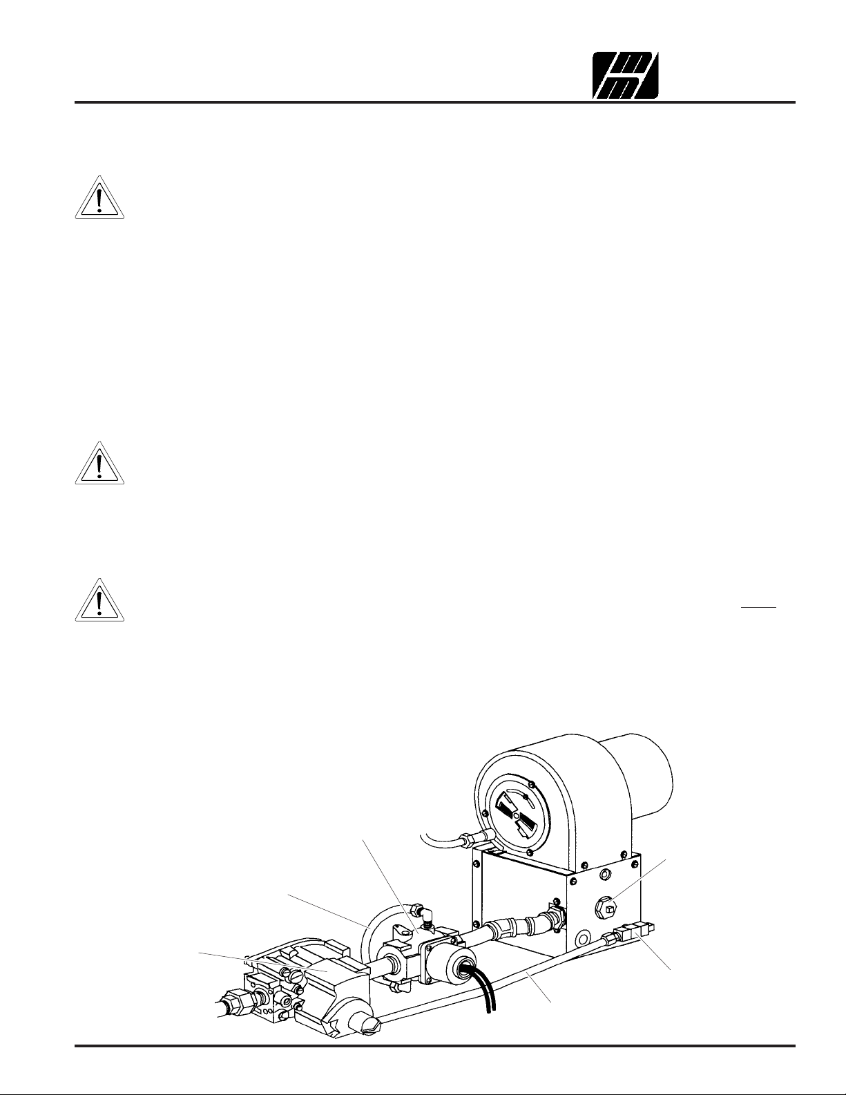
2.1 Unscrew the brass fittings at both ends of the aluminum pilot tubing that connects the pilot orifice to the combination gas control
valve. This allows the tubing to be removed. See Figure 1.
Figure 1
Conversion component locations
Solenoid valve
(PS360WB70 only)
Low flame bypass
(PS360WB70 only)
Combination gas
control valve
Aluminum
pilot tubing
p/n 36857 P. Jan 98 Rev. B Page 1 of 4
Main
orifice
holder
Pilot
orifice
Page 2
2.2 Remove and retain the aluminum pilot tubing from the burner
assembly. The end of the tubing that enters the combination gas
control valve should be removed first.
2.3 Remove and retain the pilot orifice by unscrewing it (counterclockwise)
from the burner plenum wall.
Figure 2
Pilot orifice assembly
Pilot tubing connector
2.4 Unscrew and retain the pilot tubing connector and the pilot tap plug
from the ends of the pilot orifice, as shown in Figure 2. When these
attachments have been removed, discard the pilot orifice.
2.5 Screw the pilot tubing connector and the pilot tap plug into place in
the new propane pilot orifice (p/n 31819). Tighten them to a snug fit.
2.6 Screw the new propane pilot orifice into its opening in the plenum
wall. Tighten it to a snug fit. Ensure that the end of the orifice holding
the pilot tubing mount points towards the piping assembly.
2.7
Replace the aluminum pilot tubing that was removed in Step 2.2, above.
2.8 Screw in the brass fittings at both ends of the aluminum pilot tubing.
Tighten them to a snug fit. DO NOT OVERTIGHTEN THE FITTINGS.
3. MAIN ORIFICE REPLACEMENT
3.1 Remove and retain the main orifice holder by unscrewing it
(counterclockwise) from the burner plenum wall.
3.2 Unscrew and discard the main orifice from the inner end of the holder,
as shown in Figure 3.
3.3 Screw the new propane main orifice (p/n 31822) into the orifice holder.
Tighten it to a snug fit.
3.4 Replace the main orifice holder into its opening in the burner plenum.
Tighten it to a snug fit.
4.
LOW FLAME ORIFICE REPLACEMENT
4.1 Unscrew the brass fittings at both ends of the aluminum low flame
tubing. This allows the tubing to be removed. See Figure 4.
(PS360WB70 only)
Pilot tap plug
Pilot orifice
Figure 3
Main orifice and holder
Main orifice
holder
Main orifice
Main manifold tap
plug (leave in place)
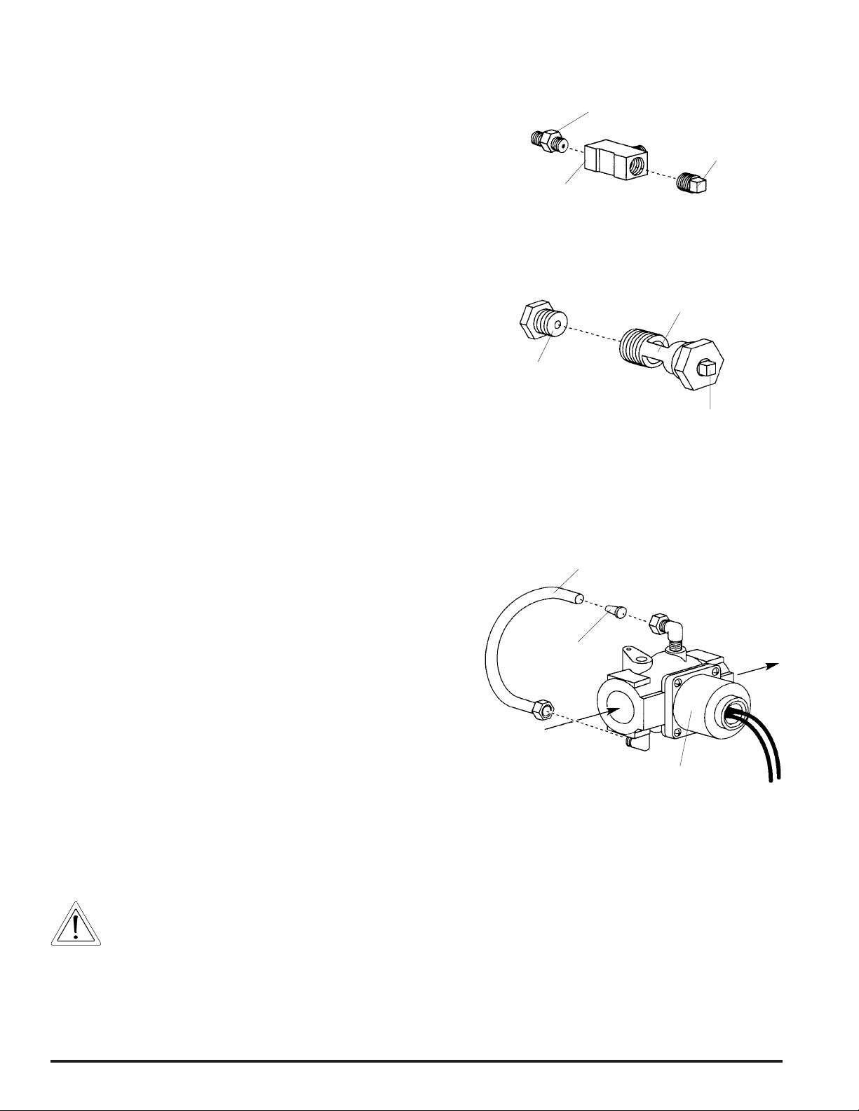
Figure 4
Low flame orifice replacement
Aluminum
tubing
4.2 Remove and retain the tubing from the solenoid valve.
4.3 Remove and discard the low flame orifice from the end of the low
flame tubing.
4.4 Insert the new propane low flame orifice (p/n 22174-0009) into the
discharge end of the low flame tubing, as shown in Figure 4.
4.5 Replace the low flame tubing into the fittings on the solenoid valve.
4.6 Screw in the brass fittings at both ends of the aluminum low flame
tubing. Tighten them to a snug fit.
Low flame
orifice
From combination
gas control valve
To burner
Solenoid valve
5. GAS LEAK TEST
5.1 Paint all pipe connections from the gas union to the burner plenum, and the aluminum pilot and low flame orifice tubing connections,
with a solution of soap and water (2/3 soap, 1/3 water is recommended). Any bubbles that are visible indicate a gas leak.
5.2 If a gas leak is detected, tighten the affected joints and connections. If tightening the connections fails to stop the leak, replace
the affected component and repeat the gas leak test.
WARNING - FIRE / EXPLOSION HAZARD
Hidden gas leaks can cause a flashback in the machinery compartment. THIS CAN CAUSE SEVERE INJURY OR
DEATH. Stand well clear when switching on the heating circuit.
5.3 If no leaks are detected by the test, switch on the oven. Switch on the heating circuit to ignite the main burner.
5.4 With the burner in operation, paint all gas pipe joints with the solution of soap and water.
5.5 If any further gas leaks are detected, shut down the oven. Reseal and tighten the affected joints and connections. If tightening
the connections fails to stop the leak, replace the affected component(s) and repeat the gas leak test.
Page 2 of 4 P. Jan 98 Rev. B p/n 36857
Page 3

6. INLET PRESSURE CHECK
6.1 Check the gas control inlet pressure at the inlet pressure tap. See Figure 6. An inlet pressure of 6-14” (14.9-34.9mbar) is
recommended for propane operation.
6.2 If the inlet pressure is:
• HIGHER THAN 14” W. C. (34.9mbar) - This pressure may damage the combination gas control valve. Decrease the supplied
gas pressure.
• LOWER THAN 3” W. C. (7.46mbar) - It may be necessary to increase the supplied gas pressure.
If it is necessary to adjust the gas line pressure, have the customer contact the gas utility supplier.
7. PILOT PRESSURE ADJUSTMENT
7.1 Ensure that the air supply is properly adjusted for propane operation.
• Units with a burner blower air shutter (see Figure 5) should have the shutter opening (at its outside edge) set to 5/16”
(7.94mm). A drill bit can be used to check the adjustment of this opening.
• Units without the air shutter (see Figure 5) should have the burner air supply adjustment screw turned 11-17 full revolutions
clockwise from the fully closed (counterclockwise) position. The screw is located on the front wall of the burner plenum, and
is surrounded by a “MORE AIR” label.
Figure 5
Insert a 5/16”
(7.94mm) drill
bit to measure
opening
(remove before
operation)
Burner blower configurations
External
air
shutter
Blowers without
external air shutter
OR
7.2 Before proceeding:
• For a PS360EWB oven, the set point should be reduced
below the room temperature.
• For a PS360WB70 oven, set the oven to low flame.
Figure 6
Gas pressure measurement/adjustment locations
7.3 Measure the pilot pressure at the pilot pressure tap, as shown
in Figure 6. The gas pressure should be 5-6” W. C. (12.5-
14.9mbar) for proper operation.
7.4 If necessary, adjust the pilot pressure as follows:
• Remove the pilot adjustment cap screw.
• Using a screwdriver, turn the inner adjustment screw
counterclockwise to increase, or clockwise to decrease,
the pilot gas pressure.
• Replace the cap screw and tighten it firmly.
7.5 Measure the current across the pilot flame sensor. The
current must measure at least 2.0
is too low, recheck the pilot pressure as per Step 7.3. If the
pressure reading is correct, consult the factory; otherwise,
repeat Steps 7.4 and 7.5.
µA. If the current reading
Pressure
regulator cap
screw
Inlet pressure
tap
adjustment
cap screw
Main orifice
pressure tap
8. MAIN MANIFOLD PRESSURE ADJUSTMENT
8.1 With the oven set to high flame, measure the regulated gas
pressure to the burner. The outlet pressure should be
checked at the main orifice pressure tap. See Figure 6.
The gas pressure should be 3” W. C. (7.46mbar) for proper
operation.
8.2 If necessary, adjust the pressure regulator as follows:
• Remove the pressure regulator cap screw.
• Using a screwdriver, turn the inner adjustment screw clockwise to increase, or counterclockwise to decrease, the main
burner gas pressure.
• Replace the cap screw and tighten it firmly.
Pilot pressure
tap
Pilot tube
connects
here
Pilot
8.3 Record the final measured regulated gas pressure on the silver conversion information label (included in the kit).
p/n 36857 P. Jan 98 Rev. B Page 3 of 4
Page 4

9. CONVERSION LABELING
9.1 Remove and discard the round, green “NAT.” label from the
front face of the burner plenum.
9.2 Apply the round, red “LPG.” label (p/n 22500-0065) to the front
face of the burner housing as shown in Figure 7.
9.3 Close the machinery compartment access door.
9.4 Record the information requested on the silver conversion
information label. Figure 8 shows a representation of this label.
9.5 Apply the conversion information label to the front of the
machinery compartment access door, next to the control panel.
See Figure 9.
Figure 8
Conversion information label
Signature of technician
performing conversion
Red “LPG.” label placement
Upper oven
label location
Date of conversion
Figure 7
(on burner housing)
Lower oven
label location
THIS APPLIANCE HAS BEEN CONVERTED ON _______________ TO ______________ GAS WITH KIT
NO. ________________ BY _______________ , WHO ACCEPTS THE RESPONSIBILITY FOR
36856
PROPANE
THE CORRECTNESS OF THIS CONVERSION.
MODEL NO. MAIN BURNER ORIFICE SIZE MANIFOLD PRESSURE
INPUT RATING MAXIMUM INLET PRESSURES
Stated on the
oven’s data plate
175,000 BTU
.185”/4.70mm
14” W.C./34.9mbar
Measured value
recorded in Step 8.3
Figure 9
Conversion information label placement
THIS APPLIANCE HAS BEEN CONVERTED ON _______________ TO ______________ GAS WITH KIT
NO. ________________ BY _______________ , WHO ACCEPTS THE RESPONSIBILITY FOR
THE CORRECTNESS OF THIS CONVERSION.
MODEL NO. MAIN BURNER ORIFICE SIZE MANIFOLD PRESSURE
INPUT RATING MAXIMUM INLET PRESSURES
PS360EWB placement
THIS APPLIANCE HAS BEEN CONVERTED ON _______________ TO ______________ GAS WITH KIT
NO. ________________ BY _______________ , WHO ACCEPTS THE RESPONSIBILITY FOR
THE CORRECTNESS OF THIS CONVERSION.
MODEL NO. MAIN BURNER ORIFICE SIZE MANIFOLD PRESSURE
INPUT RATING MAXIMUM INLET PRESSURES
PS360WB70 placement
Page 4 of 4 P. Jan 98 Rev. B p/n 36857
 Loading...