

Page 1
PS360G Series PN 70071, Rev C
Gas March 10, 2014
Domestic & Std. Export
ENGLISH
PS360G Series Gas Ovens
Model: Combinations:
PS360G Gas
Single Oven
Double Oven (Two-Stack)
Triple Oven (Three-Stack)
OWNER’S OPERATING AND
INSTALLATION MANUAL
for domestic and standard export ovens
© 2014 Middleby Marshall Inc.
is a registered trademark of Middleby Marshall, Inc. All rights reserved.
Page 2

NOTICE:
This Owner’s Operating and Installation Manual
should be given to the user. The operator of the
oven should be familiar with the function and
operation of the oven.
This manual must be kept in a prominent, easily
reachable location near the oven.
Ovens are shipped from the factory configured for
use with Natural gas. If permitted by local, national
and international codes, at the time of installation
the oven may be converted to Propane gas
operation. This conversion requires the use of a
Gas Conversion Kit that is supplied with the oven.
For CE-approved ovens, the conversion is
described in the Installation section of this manual.
For domestic and standard export ovens,
instructions are included in the Gas Conversion Kit.
It is suggested to obtain a service contract with a
Middleby Authorized Service Agent (ASA).
WARNING
POST IN A PROMINENT LOCATION, THE
EMERGENCY TELEPHONE NUMBER OF YOUR
LOCAL GAS SUPPLIER AND INSTRUCTIONS
TO BE FOLLOWED IN THE EVENT YOU SMELL
GAS.
Instructions to be followed in the event the user
smells gas shall be obtained by consulting the local
gas supplier. If the smell of gas is detected,
immediately call the emergency phone number of
your local gas company. They will have personnel
and provisions available to correct the problem.
WARNING
FOR YOUR SAFETY, DO NOT STORE OR USE
GASOLINE OR OTHER FLAMMABLE VAPORS
AND LIQUIDS IN THE VICINITY OF THIS OR ANY
OTHER APPLIANCE.
WARNING
Improper installation, adjustment, alteration,
service, or maintenance can cause property
damage, injury, or death. Read the installation,
operation, and maintenance instructions
thoroughly before installing or servicing the
equipment.
DO NOT SPRAY AEROSOLS IN THE VICINITY OF
THIS APPLIANCE WHILE IT IS IN OPERATION.
An electrical wiring diagram for the oven is located
inside the machinery compartment.
It is the customer’s responsibility to report any
concealed or non-concealed damage to the freight
company. Retain all shipping materials until it is
certain that the equipment has not suffered
concealed shipping damage.
CONTACT YOUR MIDDLEBY AUTHORIZED
SERVICE AGENT TO INSTALL AND PERFORM
MAINTENANCE AND REPAIRS AND IF
NECESSARY TO CONVERT EQUIPMENT FOR USE
WITH OTHER GASES. AN AUTHORIZED SERVICE
AGENCY DIRECTORY IS SUPPLIED WITH YOUR
OVEN.
Using parts other than genuine Middleby Marshall
Factory manufactured parts relieves the manufacturer
of all warranty and liability.
Middleby Marshall (Manufacturer) reserves the right
to change specifications at any time.
The equipment warranty is not valid unless the oven
is installed, started and demonstrated under the
supervision of a factory certified installer.
THE EQUIPMENT IS ONLY FOR PROFESSIONAL
USE AND SHALL BE USED BY QUALIFIED
PERSONNEL.
WARNING
IMPORTANT
IMPORTANT
NOTICE
NOTICE
NOTICE
NOTICE
NOTICE
RETAIN THIS MANUAL FOR FUTURE REFERENCE
ii
Page 3

Model No. _________________________
t
Modéle No.
Serial No. _________________________
Serié No.
Installation Date____________________
Date d’installation
MIDDLEBY MARSHALL
NO QUIBBLE LIMITED WARRANTY
(U.S.A.
MIDDLEBY MARSHALL, HEREINAFTER REFERRED TO AS
“THE SELLER”, WARRANTS EQUIPMENT MANUFACTURED BY IT TO BE FREE FROM DEFECTS IN MATERIAL
AND WORKMANSHIP FOR WHICH IT IS RESPONSIBLE.
THE SELLER’S OBLIGATION UNDER THIS WARRANTY
SHALL BE LIMITED TO REPLACING OR REPAIRING AT
SELLER’S OPTION, WITHOUT CHARGE, ANY PART
FOUND TO BE DEFECTIVE AND ANY LABOR AND
MATERIAL EXPENSE INCURRED BY SELLER IN
REPAIRING OR REPLACING SUCH PART. SUCH
WARRANTY SHALL BE LIMITED TO THE ORIGINAL
PURCHASER ONLY AND SHALL BE EFFECTIVE FOR A
PERIOD OF ONE YEAR FROM DATE OF ORIGINAL
INSTALLATION OR 18 MONTHS FROM DATE OF
PURCHASE, WHICHEVER IS EARLIER, PROVIDED THAT
TERMS OF PAYMENT HAVE BEEN FULLY MET.
This warranty is valid only if the equipment is installed, started,
and demonstrated under the supervision of a factoryauthorized installer.
Normal maintenance functions, including lubrication, cleaning
or customer abuse, are not covered by this no quibble
warranty.
Seller shall be responsible only for repairs or replacements of
defective parts performed by Seller’s authorized service
personnel. Authorized service agencies are located in
principal cities throughout the contiguous United States,
Alaska and Hawaii. This warranty is valid in the 50 United
States and is void elsewhere unless the product is purchased
through Middleby International with warranty included.
The foregoing warranty is exclusive and in lieu of all other
warranties, expressed or implied. There are no implied
warranties of merchantability or of fitness for a particular
purpose.
The foregoing shall be the Seller’s sole and exclusive
obligation and Buyer’s sole and exclusive remedy for any
action, including breach of contract or negligence. In no event
shall Seller be liable for a sum in excess of the purchase price
of the item. Seller shall not be liable for any prospective or lost
profits of the buyer.
This warranty is effective on Middleby Marshall equipmen
sold on, or after February 15, 1995.
Middleby Cooking Systems Group 1400 Toastmaster Drive Elgin, IL 60120 (847) 741-3300 FAX (847) 741-4406
ONLY)
The Seller warrants equipment manufactured by it to be free
from defects in material and workmanship for which it is
responsible. The Seller’s obligation under this warranty shall be
limited to replacing or repairing, at Seller’s option, without
charge, F.O.B. Seller’s factory, any part found defective and
any labor and material expense incurred by Seller in repairing
or replacing such part. Such warranty is limited to a period of
one year from the date of original installation or 15 months from
date of shipment from Seller’s factory, whichever is earlier,
provided that terms of payment have been fully met. All labor
shall be performed during regular working hours. Overtime
premium will be charged to the Buyer.
This warranty is not valid unless equipment is installed,
started, and demonstrated under the supervision of a
factory-authorized installer.
Normal maintenance functions including lubrication, adjustment
of airflow, thermostats, door mechanisms, microswitches,
burners and pilot burners, and replacement of light bulbs, fuses,
and indicating lights, are not covered by warranty.
Any repair or replacements of defective parts shall be
performed by Seller’s authorized service personnel. Seller shall
not be responsible for any costs incurred if the work is
performed by other than the Seller’s authorized service
personnel.
When returning any part under warranty, the part must be intact
and complete, without evidence of misuse or abuse, freight
prepaid.
Seller shall not be liable for any consequential damages of any
kind which occur during the course of installation of equipment,
or which result from the use or misuse by Buyer, its employees
or others of the equipment supplied hereunder, ad Buyer’s sole
and exclusive remedy against Seller for any breach of the
foregoing warranty or otherwise shall be for the repair or
replacement of the equipment or parts thereof affected by such
breach.
The foregoing warranty shall be valid and binding upon Seller if
and only if Buyer loads, operates and maintains the equipment
supplied hereunder in accordance with the instruction manual
provided to Buyer. Seller does not guarantee the process of
manufacture by Buyer or quality of product to be produced by
the equipment supplied hereunder and Seller shall not be liable
for any prospective or lost profits of Buyer.
THE FOREGOING WARRANTY IS EXCLUSIVE AND IN LIEU
OF ALL OTHER EXPRESS AND IMPLIED WARRANTIES
WHATSOEVER, SPECIFICALLY THERE ARE NO IMPLIED
WARRANTIES OF MERCHANTABILITY OR FITNESS FOR A
PARTICULAR PURPOSE.
The foregoing shall be Seller’s sole and exclusive obligation
and Buyer’s sole and exclusive remedy for any action, whether
in breach of contract or negligence. In no event shall Seller be
liable for a sum in excess of the purchase price of the item.
www.middleby.com
MIDDLEBY MARSHALL
OVEN LIMITED WARRANTY
(Non U.S.A.)
iii
Page 4

TABLE OF CONTENTS
SECTION 1 - DESCRIPTION Page
I. OVEN USES / MODELS ...…….………..1
II. OVEN COMPONENTS …….……………1
A. Conveyor Motor Drive
B. Crumb Pans
C. Conveyor
D. End Plugs
E. Eyebrows
F. Window
G. Control Box Door
H. Serial Plate
I. Control Panel
J. Photo Eye
K. Gas Burners
L. Blowers
M. Air Fingers
III. OVEN SPECIFICATIONS……………….2
A. Dimensions …………………………2
B. General Specifications ……………..2
C. Electrical Specifications ……………2
D. Gas Specifications ………………….2
SECTION 2 - INSTALLATION
I. GENERAL ………………………… 3
II. REQUIRED KITS & EQUIPMENT………4
II. BASE/TOP KITS
A. SINGLE OVEN BASE/TOP KIT ……..5
B. DOUBLE OVEN BASE/TOP KIT ……6
C. TRIPLE OVEN BASE/TOP KIT ……..7
III. OVEN LAYOUTS
A. SINGLE OVEN LAYOUT ……………8
B. DOUBLE STACKED LAYOUT ……. 9
C. TRIPLE STACKED LAYOUT ………10
IV. VENTILATION SYSTEM..………………..11
A. Requirements ……………………….11
B. Recommendations ………………….11
C. Other Ventilation Concerns ………..11
V. ASSEMBLY
A. Top Panel and Base Pad Assembly.12
B. Stacking ………………………………13
C. Restraint Cable Installation………….13
D. Conveyor Installation ………………..14
VI. ELECTRICAL SUPPLY ………………….15
VII. GAS SUPPLY
A. Gas Rough-In Recommendations….16
B. Connection……………………………17
C. Gas Conversion………………………17
D. Propane Conversion…………………17
E. Adjusting Max Pressure Setting…….17
F. Adjusting Min Pressure Setting……..18
G. Checkout………………………………18
H. Maintenance…………………………..18
SECTION 3 - OPERATION
I. DESCRIPTION OF CONTROLS
A. Control Keys……………………………….19
B. Display Features…………………………..20
II. NORMAL OPERATION
A. Starting the Oven………………………….20
B. Adjusting the Temperature……………….20
C. Adjusting the Belt Time……………………21
D. Turning the Oven OFF…………………….21
III. OTHER ADJUSTMENTS (MANAGER MODE)
A. Changing Blower Speeds…………………21
B. Changing Energy Mode Status…………...22
C. System Setup……………………………….22
1. Actual temperature display
2. Set temperature lock
3. Belt time lock
4. Degrees Celsius or Fahrenheit.
D. Energy Management Information………...23
IV. TROUBLESHOOTING INFORMATION
A. Troubleshooting Guide……………………24
B. Alerts, Errors and Remedies……………..25
SECTION 4 - MAINTENANCE
I. MAINTENANCE – DAILY………………………26
II. MAINTENANCE – MONTHLY…………………27
III. MAINTENANCE – 3 MONTH…………………..28
IV. MAINTENANCE – 6 MONTH…………………..29
V. KEY SPARE PARTS……………………………30
SECTION 5 – WIRING DIAGRAMS………....31–32
iv
Page 5
SECTION 1 - DESCRIPTION
I. OVEN USES
The PS360G Series ovens can be used to bake and/or
cook a wide variety of products, such as pizza, pizzatype products, cookies, sandwiches and others.
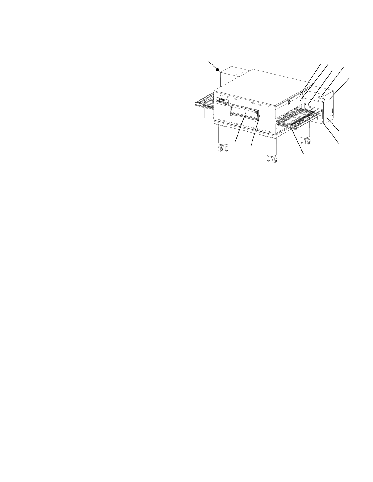
II. OVEN COMPONENTS – See Figure 1-1
A. Conveyor Drive Motor (inside cabinet):
Moves the conveyor
B. Crumb Pans: Catch crumbs and other
materials that drop through the conveyor belt.
One crumb pan is located at each end of the
conveyor belt.
C. Conveyor: Moves the food product through
the oven.
D. End Plugs: Allow access to the oven’s interior.
E. Eyebrows: Can be adjusted to various heights to lessen heat loss to the environment
F. Window: Allows the user to access the food products within the baking chamber, or place product into the
oven for shorter bake times.
G. Control Cabinet Doors: Allow access to the oven’s control components. No user serviceable parts are
located within these cabinets.
H. Serial Plate: Provides specifications for the oven pertinent to installation, operation and maintenance. Refer
to SECTION 2 – INSTALLATION for details.
I. Control Panel (User Interface): Allows user to adjust temperature, bake time and top and bottom air flow.
Also provides diagnostic messages for oven operation.
J. Photo Sensor: Puts oven into the Baking Mode when the beam is interrupted by product being placed on the
belt.
K. Door Photo Sensor: Puts oven into the Baking Mode when the beam is interrupted by the front window
being opened to insert product.
L. Circuit Breaker Resets: Permits resetting breakers inside cabinet without opening door or touching the
circuit breakers directly.
M. Gas Burner (inside left control cabinet): Heat recirculating air within the oven cavity.
N. Blowers (not shown): move heated air that recirculates through the oven cavity.
O. Fingers (inside top and bottom of oven cavity): Direct air in controlled fashion to the product being baked
through a pattern arrangement of extruded holes.
B
F
F
D E
K
C
I
J
H
G
A
1
Page 6

”
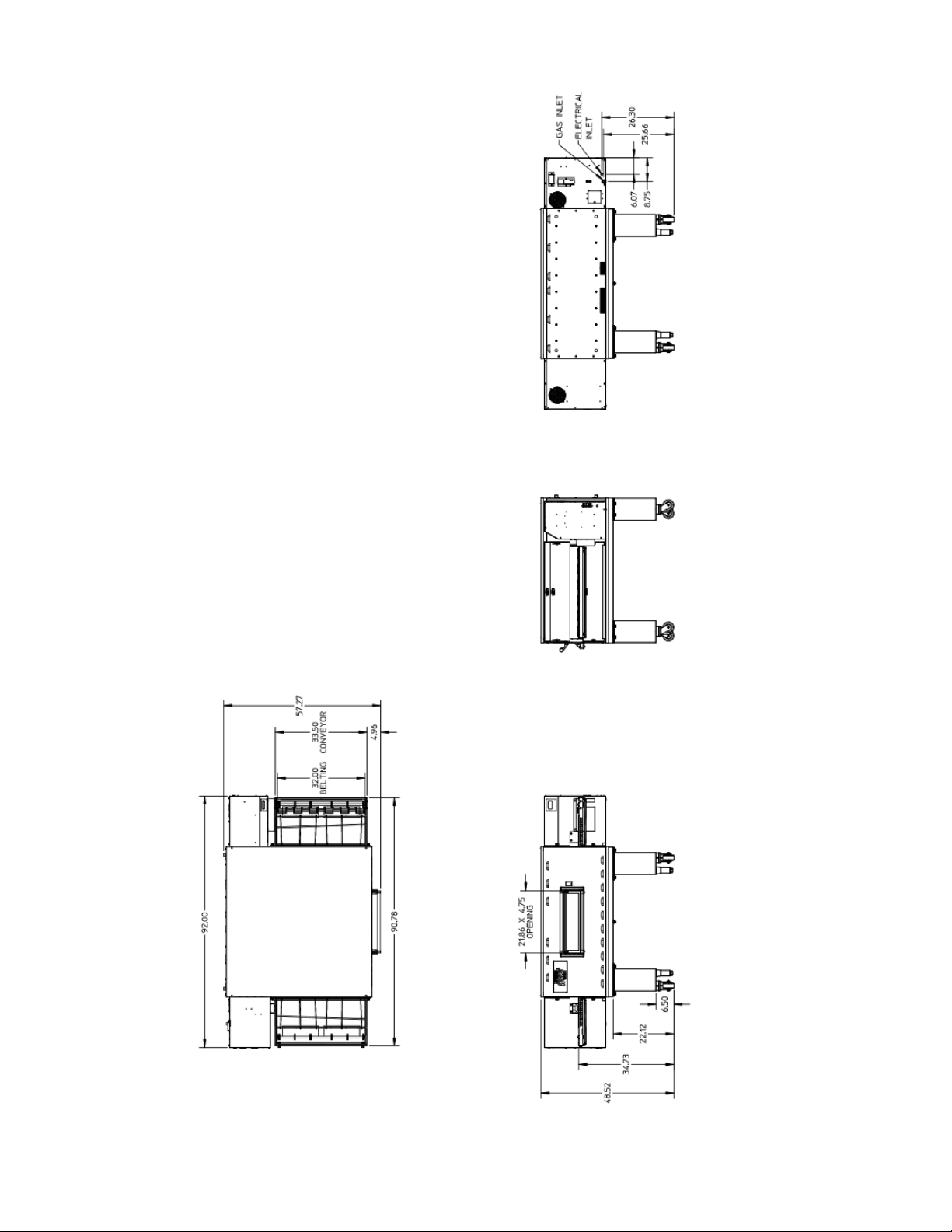
III. OVEN SPECIFICATIONS – PS360G
Table 1-1 Dimensions
Overall Height 48.52” (1232.4 mm) 68.21” (1732.5 mm) 80.53” (2045.5 mm)
Overall Depth 57.40” (1458 mm) 57.40” (1458 mm) 57.40” (1458 mm)
Overall Length 92.00” (2337 mm) 92.00” (2337 mm) 92.00” (2337 mm)
Conveyor Width – Belt width is 32” 33.5” (850.9 mm) 33.5” (850.9 mm) 33.5” (850.9 mm)
Recommended Minimum Clearances
Rear of Oven to Wall 0” (0 mm)
Right Side of Oven to Wall 2” (50.8 mm)
Left Side of Oven to Wall 2” (50.8 mm)
Table 1-2: General Specifications 32” Belt
Weight 1,100 lbs.
Rated Heat Input (per oven cavity) 119,900 BTU/hr
Maximum Operation Temperature 600°F
Air Blowers 4 at 2,800 rpm
Warm-up Time 20 minutes to 500°F
Table 1-3: Electrical Specifications
Single Oven Double Oven Triple Oven
Main Blower
Voltage
Control Circuit
Voltage
Phase Frequency
Current
Draw
Poles Wires
230 VAC, 3φ 24VDC 1 50-60 Hz 7 Amps 2 3 Wire – L1, L2/N & GRND
Table 1-4: Gas Orifice and Pressure Specifications
Gas Type
Natural
Propane
GAS ORIFICE AND PRESSURE SPECIFICATIONS (PER OVEN CAVITY) – CE OVENS
Gas
G20
G25
G30
G31
Main Orifice
Diameter
.120
3.048 mm
.120”
3.048 mm
.0748”
1.90mm
.0748”
1.90mm
Type
Natural
Natural
Butane
Propane
AT,BG,CR,
CZ,DK,EE,
FI,GR,HR,
HU,IS,IE,
IT,LV,LT,
NO,PT,RO,S
K,SI,ES,
SE,CH,TR,G
B
Main Orifice
Diameter
.120”
(#31)
.0748”
(1.90mm)
DE,
LU,
NL
PL
I
2H
20mbar --
--
-- -- -- -- -- --
-- -- -- -- 37 mbar 50 mbar -- 30 mbar
I
2L
25
mbar
I
2E
20
mbar
-- -- -- -- -- -- -- --
Inlet Pressure Manifold Pressure Bypass Pressure
6-8” W.C.
(14.9 - 19.9 mbar)
11-14” W.C.
(27.4 – 34.9 mbar)
FI,CR,GR,
BE,FR
IE,HR,LU,
NL,PL,SK,
SI,ES,CH,
TR,GB,CY,C
Z,DE,MT,SK
I
I
2E+
20/25
mbar
I
3P
-- -- -- -- -- --
CY,CZ,
DE,
MT,SK
3.5” W.C. at manifold
(8.7 mbar)
10.0” W.C.
(24.9 mbar)
SW,CH,
AT,DK,
NO,FI,
NI,CR,
FR
I
3P
I
3B/P
28-30/50
mbar
BG,CY,CR,C
Z,DK,EE,FI,
GR,HR,
LV,LT,LU,
MT,NL,NO,S
K,SI,SE,
TR
30 mbar
PL /
AT,DE,
HU,SK,
CH
I
3B/P
3B/P
37/50
mbar
37/50
mbar
0.35-0.36” W.C. at manifold
(0.9 mbar)
0.9-1.0” W.C.
(2.2-2.5 mbar)
BE,CY,CZ,
EE,FR,
GR,IE,IT,
LT,LU,LV,P
T,RO,SK,E
S,CH,
GB,PL
I
3+
28-30
mbar
37 mbar
Orifice
Manifold
Pressure
3.5” w.c.
8.7mbar
3.5” w.c.
8.7mbar
10.0” w.c.
24.9 mbar
10.0” w.c.
24.9 mbar
Rated
Heat
Input
35.2kW
35.2kW
35.2kW
35.2kW
NOTE
Wiring Diagrams are contained in Section 5 of this Manual and are also located inside the oven
control compartment. Additional electrical information is provided on the oven’s serial plate.
THIS MANUAL MUST BE KEPT FOR FUTURE REFERENCE
2
Page 7

SECTION 2 - INSTALLATION
I. GENERAL
WARNING – After any conversions, readjustments, or service work on the oven:
Perform a gas leak test
Test for correct air supply, particularly to the burner
blower.
WARNING – Keep the appliance area free and clear of combustibles.
WARNING – The oven must be installed on an even (level) non-flammable flooring and any adjacent walls must
not be flammable. Recommended minimum clearances are specified in the Description section of this manual.
WARNING – Do not obstruct the flow of ventilation air to and from your oven. There must be no
obstruction around or underneath the oven. Constructional changes to the area where the oven is
installed shall not affect the air supply to the oven.
CAUTION: To reduce the risk of fire, the appliance is to be mounted on floors of non-combustible construction with
noncombustible flooring and surface finish and with no combustible material against the underside thereof, or on
noncombustible slabs or arches having no combustible material against the underside thereof, such construction
shall in all cases extend not less that 12 inches (304 mm) beyond the equipment on all sides.
CAUTION: For additional installation information, contact your local Authorized Service Agent.
NOTE – There must be adequate clearance between the oven and combustible construction. Clearance must also
be provided for servicing and proper operation.
NOTE – An electrical wiring diagram for the oven is located inside the machinery compartment.
NOTE: All aspects of the oven installation, including placement, utility connections, and ventilation requirements,
must conform to any applicable local, national, or international codes. These codes supersede the requirements
and guidelines provided in this manual.
NOTE: In the USA, the oven installation must conform to local codes. In the absence of local codes, gas oven
installations must conform to the National Fuel Gas Installation Code, ANSI Z223.1. Gas and electric ovens, when
installed must be electrically grounded in accordance with local codes, or in the absence of local codes, with the
Natural Electric Code (NEC), or ANSI/NFPA 70.
NOTE: In Canada, the oven installation must conform to local codes. In the absence of local codes, gas oven
installations must conform to the Natural Gas Installation Code, CAN/CGA-B149.1 or Propane Gas Installation
Code, CAN/CGA-B149.2, as applicable. Gas and electric ovens, when installed, must be electrically grounded in
accordance with local codes, or in the absence of local codes, with Canadian Electrical Code, CSA C22.2.
NOTE: In Australia, the oven installation must conform with local codes. In the absence of local codes, gas oven
installation must conform to the requirements of AS5601/AG601, Gas, Electricity, and any other relevant statutory
regulations.
Test for proper combustion and gas supply
Check that the ventilation system is in operation
3
Page 8
3
II. PS360G OVEN INSTALLATION – REQUIRED KITS & EQUIPMENT
TYPE OF INSTALLATION PS360G
Installation
Kit
PN 69977
PS360G Single Gas Oven 1 1 -- -PS360G Double Gas Oven 2 -- 1 -PS360G Triple Gas Oven 3 -- -- 1
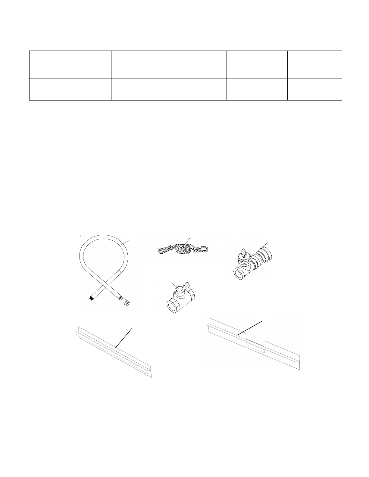
PARTS KITS FOR SERIES PS360G GAS OVEN
INSTALLATION KIT (PN 69977)
ITEM
NUMBER
1 22361-0001 FLEXIBLE GAS HOSE 3/4” 1
2 22450-0228 RESTRAINT CABLE 1
3 50546 TAP AND ADAPTER 1
4 23115-0010 GAS BALL VALVE ¾ X ¾ 1
5 55027 CONVEYOR END STOP 1
6 61823 CONVEYOR BACK STOP 1
PART
NUMBER
1
Single Oven Kit
Base w/ 15” Legs,
Casters & Top
PN 69669
Double Oven Kit
Base w/ 10” Legs,
Casters & Top
PN 70051
DESCRIPTION QTY
2
Triple Oven Kit
Base w/ 15” Legs,
Casters & Top
PN 69997
4
5
6
4
Page 9
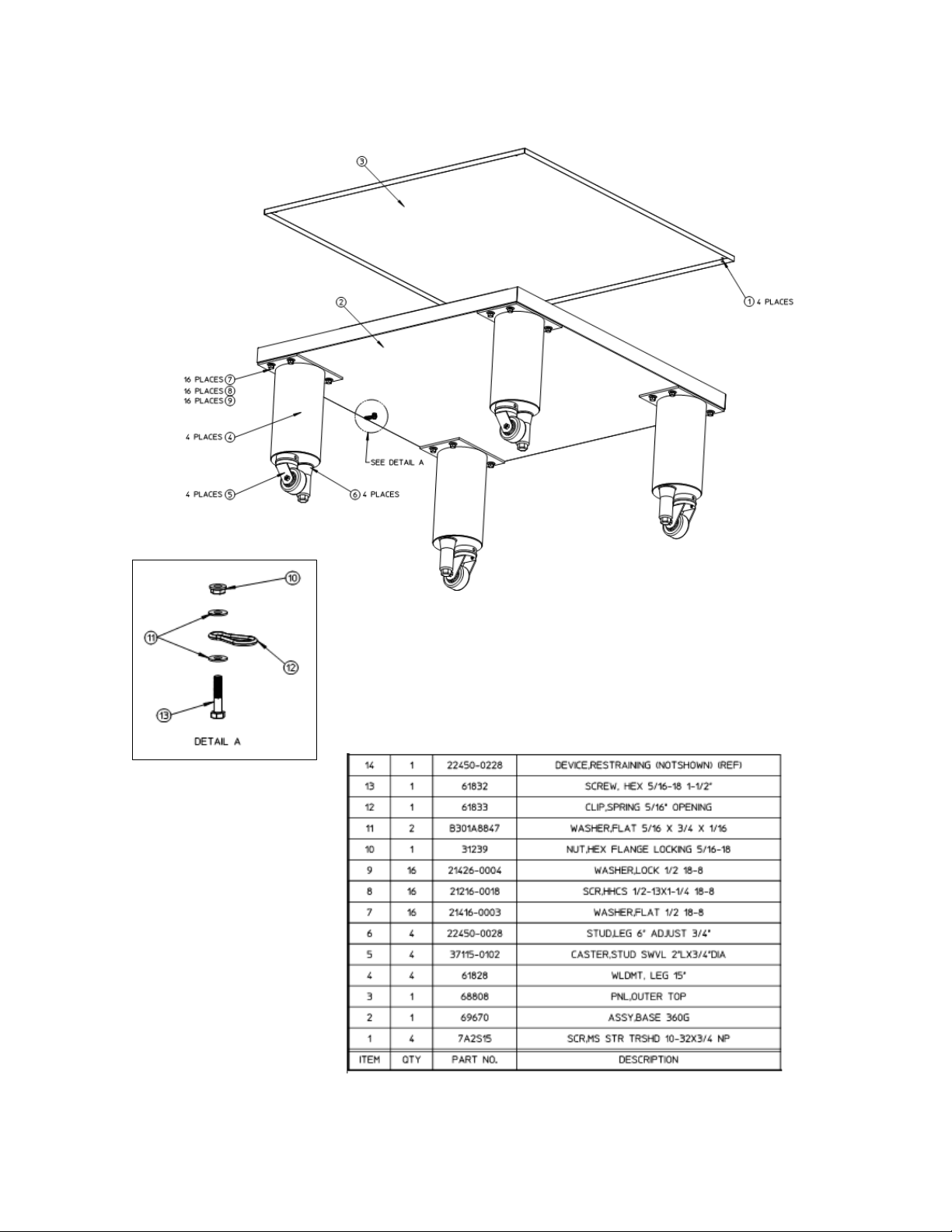
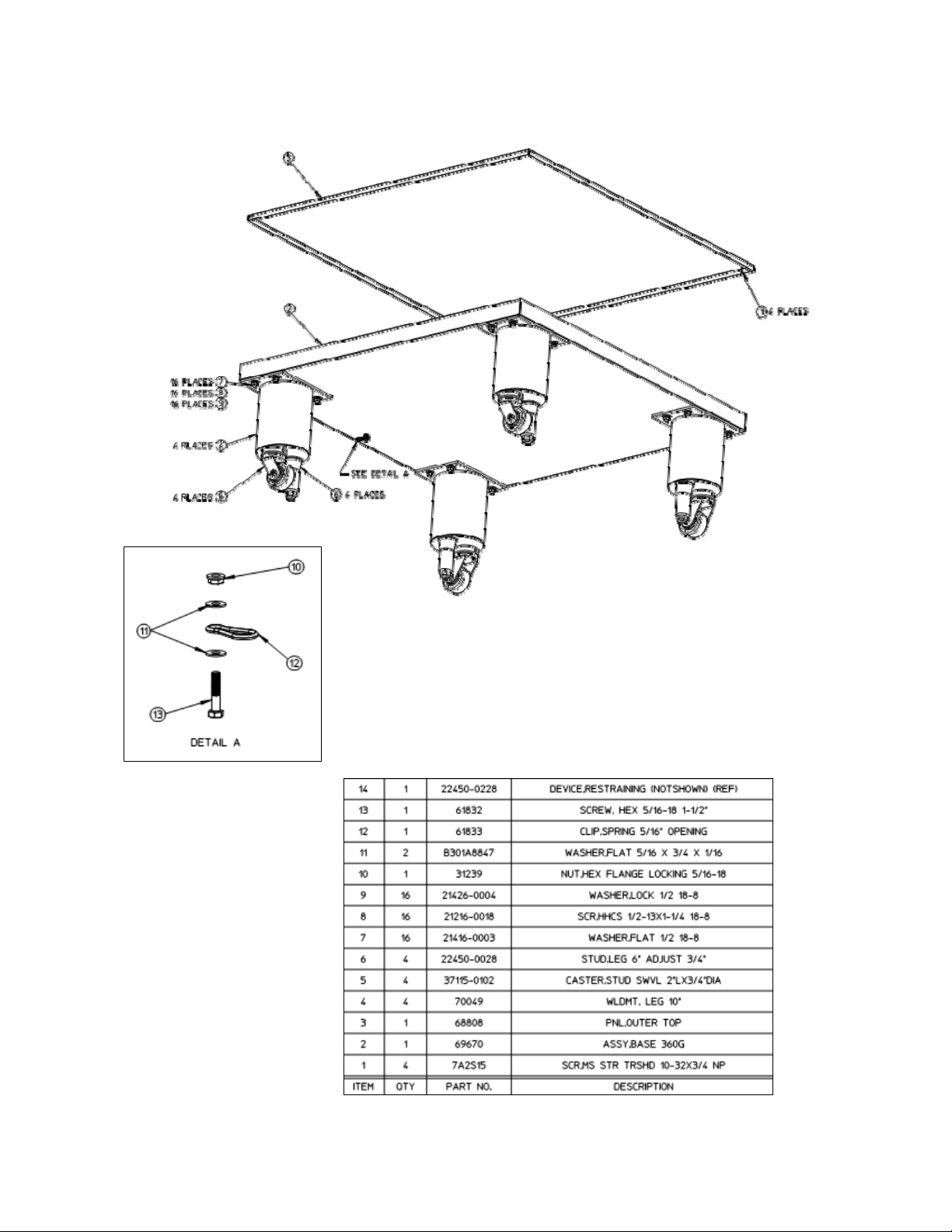
A. PN 69669 – SINGLE OVEN BASE/TOP KIT
5
Page 10
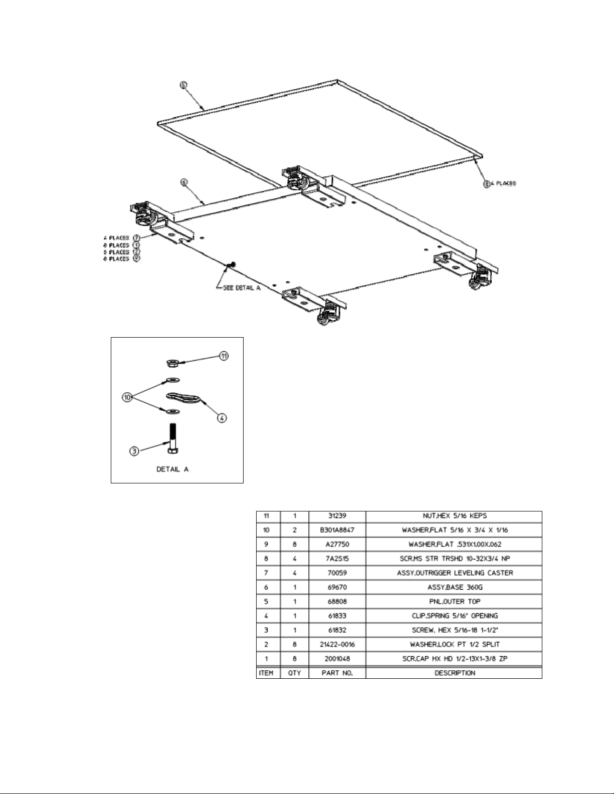
B. PN 70274 – DOUBLE OVEN BASE/TOP KIT
6
Page 11
C. PN 70275 – TRIPLE OVEN BASE/TOP KIT
7
Page 12
PS360G SINGLE OVEN
8
Page 13

PS360G DOUBLE STACK OVEN
9
Page 14

PS360G TRIPLE STACK OVEN
10
Page 15

IV. VENTILATION SYSTEM
IMPORTANT
Where national or local codes require the
installation of fire suppression equipment or
other supplementary equipment, DO NOT
mount the equipment directly to the oven.
MOUNTING SUCH EQUIPMENT ON THE
OVEN MAY:
VOID AGENCY CERTIFICATIONS
RESTRICT SERVICE ACCESS
LEAD TO INCREASED SERVICE
EXPENSES FOR THE OWNER
A. Requirements
CAUTION: Gas oven installations REQUIRE a
mechanically driven ventilation system
with electrical air sensing control.
A mechanically driven ventilation system is STRONGLY
RECOMMENDED for electric oven installations.
PROPER VENTILATION OF THE OVEN IS THE
RESPONSIBILITY OF THE OWNER.
B. Recommendations
NOTE THAT THE HOOD DIMENSIONS SHOWN IN
FIGURE X-X ARE RECOMMENDATIONS ONLY.
NATIONAL, AND INTERNATIONAL CODES MUST BE
FOLLOWED WHEN INSTALLING THE VENTILATION
SYSTEM. ANY APPLICABLE CODES SUPERCEDE THE
RECOMMENDATIONS SHOWN IN THIS MANUAL. IN
AUSTRALIA, COMPLIANCE TO REGULATIONS
AS5601/AG601 IS MANDATORY.
The rate of air flow exhausted through the ventilation
system may vary depending upon the oven configuration
and hood design. Consult the hood manufacturer or
ventilation engineer for these specifications.
To avoid negative pressure condition in the kitchen area,
return air must be brought back to replenish the air that
was exhausted. A negative pressure in the kitchen can
cause heat related problems to the oven components as if
there were no ventilation at all. The best method of
supplying return air is through heating, ventilation and air
conditioning (HVAC) system. Through the HVAC system,
the air can be temperature-controlled for summer and
winter. Return air can also be brought in directly from
outside the building, but detrimental effects can result from
extreme seasonal hot and cold temperatures from the
outdoors.
NOTE: Return air from the mechanically driven system
must
not blow at the opening of the baking chamber. Poor
oven baking performance will result.
C. Other ventilation concerns
1. Special locations, conditions, or problems may require
the services of a ventilation engineer or specialist.
2. Inadequate ventilation can inhibit oven performance.
3. It is recommended that the ventilation system and duct
work be checked at prevailing intervals as specified by
the hood manufacturer and/or HVAC engineer or
specialist.
LOCAL,
FIG 2-5. Ventilation System Dimensional
11
Page 16

SC
)
V. ASSEMBLY
A. Top Panel and Base Pad Assembly
1. Install the four leg extensions onto the base pad using
the 1/2”-13 x 1-1/4” screws, 1/2” flat washers and 1/2”
lockwashers supplied in the Base Pad Kit. See Figure
2-6. Check that the orientation of the adjustable 6” leg
holes in the leg bottom is consistent (all to the inside
or all to the outside). The adjustable leg mounting
hole is closer to the edge of the leg than the caster
mounting hole. Install the spring clip for the oven
restraining cable to the hole in the bottom middle of
the base pad per the DETAIL A of the base pad kit
drawing (pages 6-8). This clip will attach to the
restraint cable that keeps the oven from moving too far
when installed on casters.
2. Install one caster and one adjustable 6” leg onto each
leg extension and tighten securely in place.
3. Install the lower oven cavity onto the base pad. See
Fig 2-7.
4. For single ovens ONLY:
Install the top panel using the screws included in the
base pad kit, as shown in Fig 2-8. Then, skip ahead to
Part C, Restraint Cable Installation.
For double or triple ovens:
Continue on to Part B, Stacking. Note that the top
panel should NOT be installed for double and triple
ovens until after stacking the oven cavities.
Fig 2-7. Base Pad Installation
ASSEMBLED
ASSEMBLED
BASE PAD
BASE PAD
BOTTOM OVEN
BOTTOM OVEN
Fig 2-6. Leg Extension and Caster Installation
Figure 2-8. Top Panel Installation
#10-32 X 3/4”
REWS (4
OVEN TOP PANEL
12
Page 17

(4)
NOTE: DO NOT install top panel onto double or triple
ovens until AFTER stacking the oven cavities. See Part B,
Stacking.
B. Stacking
For single ovens, skip ahead to Part C, Restraint Cable
Installation.
IMPORTANT
Middleby Marshall STRONGLY RECOMMENDS that the
PS360G Gas oven cavities be stacked by AUTHORIZED
PERSONNEL.
Contact your Middleby Marshall authorized Service Agent
for complete stacking instructions.
1. Stack an oven cavity on top of the lower oven. Check
the following:
Insulation is installed on the lower oven top.
All four sides of the lower lip (on the bottom edge
of the oven cavity) overlap the top of the lower
oven
The oven is level
The oven is firmly seated and the top insulation
layer is installed smoothly and fully covering the
metal panel.
See Figure 2-9.
2. For triple ovens, repeat Step 1 to install the top oven
cavity.
3. Install the top panel using the screws included in the
base pad kit, as shown in Figure 2-10.
Figure 2-9. Stacking
INSULATION
INSULATION
C. Restraint Cable Installation
Because the oven is equipped with casters, a restraint
cable assembly must be installed to limit the
movement of the appliance without depending upon
the connector and the quick disconnect device or its
associated piping. One end of the cable is anchored to
the snap clip on the underside of the base pad while
the other is anchored to the wall. See Figure 2-11.
After connecting the restraint cable, move the oven to
its final location. Adjust the bottom (hex) sections of
the adjustable legs so that the casters are off the floor.
For triple ovens, lock the two front casters.
FIGURE 2-10. Top Panel Installation
#10-32 X 3/4”
SCREWS
FLAT
WASHER
5/16” X 1-1/2”
SCREW
FIGURE 2-10. Installing the Restraint Cable
The restraint cable is connected to the spring
snap located at the back-center of the base
underside. The ¾” eyebolt must be anchored to
the wall or floor to attach the other end of the
restraint cable.
OVEN TOP PANEL
FLANGED
NUT
SPRING
SNAP
13
Page 18

D. Conveyor Installation
1. Unfold the conveyor as shown in Figure 2-12. Then
begin to slide the conveyor into the end of the oven.
The conveyor can only be installed form the side of the
oven where the drive motors are located.
2. Continue moving the conveyor into the oven until the
frame protrudes equally from each end of the oven.
Check that the crumb tray supports located on the
underside of the conveyor frame rests firmly against
the lower end plugs, as shown in Figure 2-13.
3. When the conveyor is positioned properly, check for
freedom of movement of the conveyor belt by pulling it
for about 2 to 3 feet (0.6- 1.0 m) with your fingers. The
drive and idler shafts must rotate smoothly, and the
belt must move freely without rubbing on the inside of
the oven.
4. Check the Tension of the conveyor belt as shown in
Figure 2-14. The belt should lift about 1” (25mm). DO
NOT OVER TIGHTEN THE CONVEYOR BELT.
NOTE: If necessary, the belt tension can be adjusted
by turning the conveyor adjustment screws, located at
the ider (non-control) end of the conveyor. See Figure
2-14.
Figure 2-12. Conveyor Installation
Figure 2-14. Conveyor Belt Tension
14
Page 19

5. If it is necessary to add or remove conveyor links to
achieve the correct tension, OR if it is necessary to
reverse the conveyor belt for correct orientation, the belt
will need to be removed from the conveyor frame. If this
is necessary, perform the following procedure:
Remove the conveyor assembly from the oven and
place it flat on the floor.
Remove the master links using long-nose pliers.
Then, roll up the belt along the length of the
conveyor frame.
Add or remove belt links as necessary to achieve
the correct belt tension.
Replace the belt on the conveyor frame. Check that
the conveyor belt links are oriented as shown in
Figure 2-15, and that the smooth side of the
conveyor belt faces UP.
Connect the inside master links. Check that the
links are oriented as shown in Figure 2-15.
Connect the outside master links. Note that the
outside master links each have an open hook on
one side. This hook aligns with the hooks along the
sides of the other conveyor links. See Figure 2-15.
Replace the conveyor into the oven.
Figure 2-15. Conveyor and Master Link orientation
E. Final Assembly
1. Install the crumb trays underneath the conveyor as
shown in Figure 2-16.
Figure 2-16. Crumb Trays
CONVEYOR BELT REVERSAL
Conveyor belt reversal consists of three steps:
1. Physically reversing the conveyor belt
2. Resetting the conveyor travel direction through the User
Interface.
3. Switching the photo sensor.
REVERSING THE CONVEYOR BELT
Remove the conveyor from the oven and find the master link
location. Remove master links and remove the belt from the
conveyor frame. Reassemble the belt back onto the frame
(in the reverse direction) and reinstall the master links.
Replace the conveyor assembly in the oven.
RESETTING DIRECTION
See OVEN CONFIGURATION MENU in the PS360G TECH
GUIDE. Direction is changed through the User Interface with
no wiring changes necessary.
Shock hazard in compartments electrical
filters are electrically alive.
SWITCHING PHOTO SENSOR
Disconnect power before switching Photo
Eye.
Remove the three screws securing the access door to the
unit. Open the access door and disconnect the connector
fitting to the photo eye assembly. Remove the two screws
securing the photo eye assembly to the control box. Remove
the four nuts securing the photo eye to the housing. Rotate
the photo eye 180 degrees and affix the photo eye with the
four nuts. On the opposite control box, remove the two
screws holding the cover where the photo eye assembly will
be positioned. Secure the photo eye assembly in position
with the two screws. Place the photo eye cover on the
opposite control box, where the photo eye assembly was
removed, and secure the two screws. Secure the access
door with the three screws. Remove the three screws
securing the access door on the opposite side. Open the
access door, where the photo eye is now positioned, and
connect the photo eye connector fitting. Secure the access
door with the three screws. Apply power to the unit. Adjust
the photo eye height by loosening the two screws securing
the photo eye assembly and sliding the photo eye assembly
either up or down, such that the beam is approximately 1/4
inch above the belt.
Note: This is MUCH easier in reduced light.
Replace all covers.
VI. ELECTRICAL SUPPLY
Authorized installation personnel normally
accomplish the connections for the ventilation
system, electric supply, and gas supply, as
arranged by the customer. Following these
connections, the factory-authorized installer
can perform the initial startup of the oven.
NOTE: The electric supply installation must satisfy the
requirements of the appropriate statutory authority such
as the National Electrical Code, CSA C22.2; the Australian
Code AG601; or other applicable regulations.
NOTE: The electric supply connection must meet all national
and local electrical code requirements.
15
Page 20

Figure 2-17. Utility Connection Locations
Check the oven serial plate before making any electric
supply connections. Electric supply connections must agree
with data on the oven serial plate. The location of the serial
plate is shown in Figure 1-1 (in Section 1, Description
A fused disconnect switch or a main circuit breaker
(customer furnished) MUST be installed in the electric supply
line for each oven cavity. It is recommended that the
switch/circuit breaker have Lockout/Tagout capability.
The supply conductors must be of the size and material
(copper) recommended. Refer to the wiring diagram inside
the machinery compartment of the oven. Electrical
specifications are also listed on the oven’s serial plate and in
Table 1-3, Electrical Specifications
Description
The oven requires a ground connection to the oven ground
screw. For gas ovens, the screw is located in the electrical
junction box (see Figure 2-14). If necessary, have the
electrician supply the ground wire. Do NOT use the wiring
conduit or other piping for ground connections.
Incoming electrical power lines are fed through the strainrelief fitting, shown in Figure 2-14. The electrical supply
connections are made inside the electrical junction box. The
power lines then connect to the oven circuits through safety
switches located inside the machinery compartment and
each blower motor compartment. These switches interrupt
electrical power to the oven when the Machinery
Compartment Access Panel is opened, OR when the rear
panel is removed.
Connection
Refer to the wiring diagram inside the machinery
compartment of the oven to determine the correct
connections for the electrical supply lines. Connect the
supply as indicated on the wiring diagram.
).
The terms of the oven’s warranty require all
start-ups, conversions and service work to be
performed by a Middleby Marshall Authorized
Service Agent.
(in Section 1,
).
VII. GAS SUPPLY
DURING PRESSURE TESTING NOTE
ONE OF THE FOLLOWING:
1. The oven and its individual shutoff valve must be
disconnected from the gas supply piping system during
any pressure testing of that system at test pressure in
excess of ½ psi (3.45 kPa).
2. The oven must be isolated from the gas supply piping
system by closing its individual manual shutoff during
any pressure testing of the gas supply piping system at
test pressure equal to or less than ½ psi (3.45 kPa).
3. If incoming pressure is over 14” W.C. (35 mbar), a
separate regulator MUST be installed in the line
BEFORE the individual shutoff valve for the oven.
To prevent damage to the control valve
regulator during initial turn-on of gas, it is
very important to open the manual shutoff
valve very slowly.
After the initial gas turn-on, the manual
shutoff valve must remain open except
during pressure testing as outlined in the
above steps or when necessary during
service maintenance.
A. Gas Utility Rough-In Recommendations
The following system specifications are STRONGLY
RECOMMENDED. Deviating from these recommendations
may affect the baking performance of the oven.
Gas Meter
One or two cavities: 750 CFH meter
Three oven cavities: 1,200 CFH meter
Gas Line
DEDICATED GAS LINE from the gas meter to
the oven
2” (50.8mm) pipe for Natural gas
2” (50.8mm) pipe for Propane
Maximum length: 2.002 (61m). Each 90° elbow
equals 7’ (2.13m) of pipe.
16
Page 21

B. Connection
Check the oven’s gas supply requirements before making
the gas utility connections. Gas supply requirements are
listed on the oven’s serial plate and in Table 1-4. Gas
Orifice and Pressure Specifications (in Section 1,
Description).
Check the serial plate to determine the type of gas (Propane
or Natural) to be used with the oven.
Refer to the instructions in the gas hose package (included
in the Installation Kit) before connecting the gas line. One
gas line connection method is shown in Figure 2-18;
however, compliance with the applicable standards and
regulations is mandatory.
Inlet, regulated, and pilot gas pressure readings can be
taken using a digital tube manometer at the tap location
shown in Figure 2-19. Figure 2-19 shows the burner
assembly and Figure 2-21 shows the gas valve.
NOTE: The installation must conform with local codes or in
the absence of local codes, to the National Fuel
Gas Code, ANSI Z223.1-latest edition.
Certain safety code requirements exist for the installation of
gas ovens; refer to the beginning of Section 2 for a list of the
installation standards. In addition, because the oven is
equipped with casters, the gas line connection shall be made
with a connector that complies with the Standard for
Connectors for Movable Gas Appliances, ANSI Z21.69 (in
U.S.A.), as well as a quick-disconnect device that complies
with the Standard for Quick-Disconnect Devices for Use With
Gas Fuel, ANSI Z21.41 (in U.S.A.).
C. Gas Conversion
Where permitted by local and national codes, it is possible to
convert ovens from natural gas to propane or from propane
to natural gas. Use the appropriate Middleby Gas
Conversion Kit for the specific oven model.
The terms of the oven’s warranty require all
startups, conversions and service work to be
performed by a Middleby Authorized Service
Agent.
D. PS360G Propane Conversion
Two items must be changed to change the oven to operate
on LP:
1. Replace main orifices.
2. Adjust main gas regulator per instructions below.
Disconnect the manifold union closest to the main burner,
and remove the manifold assembly (four screws). Slide out
the manifold assembly (leaving the ignition and sense wires
connected). Replace the main orifices.
Replace the main orifices on the manifold assemblies with
the LP units, and replace the manifold assembly. Reconnect
the union.
E. Adjusting the Maximum Pressure Setting
1. Disconnect pressure feedback connection (if applicable).
2. Connect a suitable pressure gauge to pipe line or to outlet
pressure tap of gas control concerned, to measure burner
pressure (measuring point must be as near to burner as
possible).
Figure 2-19. Gas Burner Assembly
FLAME TUBES
MANIFOLD
PRESSURE TAP
GAS BURNERS
3. Make sure that the appliance is in operation and the
Moduplus
® coil is energized with maximum current.
4. If maximum rate pressure needs adjustment, use an 8 mm
wrench to turn adjustment screw for maximum pressure
setting (clockwise to increase or counter-clockwise to
decrease pressure), until the desired maximum outlet
pressure is obtained.
5. Disconnect electrical connection of the Moduplus
6. Check minimum pressure setting and readjust if
necessary. (See Adjusting Minimum Pressure Setting for
proper adjusting procedure.)
7. Reconnect pressure feedback connection (if applicable).
8. If minimum and maximum pressures are set, wire the
Moduplus
® in circuit.
9. Close pressure tap screw.
17
®.
Page 22

Figure 2-20. Burner Components
AIR INTAKE BOX
GAS INLET
GAS VALVE
GAS MANIFOLD
F. Adjusting the Minimum Pressure Setting
1. Disconnect pressure feedback connection (if
applicable).
2. Connect a suitable pressure gauge to pipe line or to
outlet pressure tap of gas control concerned, to
measure burner pressure (measuring point must be as
near to burner as possible).
3. Disconnect electrical connection of the Moduplus®.
4. Energize operator, set control in operation and wait until
an outlet pressure is recorded on pressure gauge.
BURNERS
BURNER
ORIFICES
5. If minimum rate pressure needs adjustment, use an 8
mm wrench to turn adjustment screw for minimum
pressure setting (clockwise to increase or counterclockwise to decrease pressure), until the desired
minimum outlet pressure is obtained.
6. Check if main burner lights easily and reliably at
minimum pressure.
7. Reconnect pressure feedback connection (if applicable).
8. Close pressure tap screw.
G. Checkout
After any adjustment, set appliance in operation and observe
through a component cycle to ensure that burner system
components function correctly.
NOTE: The installer MUST verify oven operation prior to
putting oven into service.
H. Maintenance
It is recommended to check yearly the minimum and the
maximum setting and readjust them if necessary.
18
Page 23

SECTION 3 - OPERATION
I. DESCRIPTION OF CONTROLS – USER INTERFACE
The PS360G oven control performs a variety of functions, including
Temperature control
Belt speed control
Upper/lower blower speed setting
Energy management
Oven diagnostics and system testing
Conveyor speed calibration (Service use only)
The oven control will have power delivered to it and initialize when the oven is connected to the power supply.
Upon initialization, the control will briefly display its “WOW OVEN” splash screen, then proceed to OFF mode.
A. Control Keys
X
I/O
X
X
“UP/DOWN” keys:
“ON/OFF” key:
Quick press brings oven to active, “ON” mode.
Press and hold will put oven into “OFF” mode. If temp is over 200F the blowers will
remain on until the oven temp drops below 200F.
“TEMPERATURE” key:
Quick press displays actual temperature.
Press and hold until display flashes. Allows change to set temperature.
X
“BELT” Key:
Quick press displays alternate front and back belt speeds
Press and hold until display flashes. Allows change to belt speed.
Press up or down to change number values or change parameter.
X
BELT
”TOOLS” Key:
Press (when off) to enter “Setup” or “test” screens
X
“CANCEL” Key:
Quick press cancels last action and returns to last screen or operation.
Press and hold to shut oven off.
BELT
”RETURN” Key:
Quick press stars oven from off mode.
Enters and saves changed parameter value.
19
Page 24

B. Display Features
STATUS INDICATOR:
“BAKING” appears when the
oven is in baking mode. No
text here indicates that the
oven is in IDLE mode.
ACTUAL TEMPERATURE:
Actual temperature of the
oven is displayed here. If it is
not displayed, pressing the
Starting the Oven
TEMPERATURE key
momentarily will show the
actual temperature for 15
seconds.
II. NORMAL OPERATION
A. Starting the Oven
To start the oven, press the
screen.
The blowers will begin and the blower proving switches will engage, permitting the heat circuit relay to engage.
The
gas ignition module will begin its cycle and ignite the three inshot burners.
B. Adjusting the Temperature
BAKING
256 F
I/O
X
button. The oven will start and the operating display will appear on the
350 F
F 4:00
BELT DISPLAYED:
“F” indicates FRONT belt
time is being displayed.
“B” indicates that the
BACK belt time is being
displayed. If no letter
appears the belt times
are identical.
HEAT
BELT SPEED:
Displays time in
minutes and seconds
that it takes for the belt
to travel the length of
the baking chamber.
SETPOINT:
Set point (baking)
temperature is
displayed here.
HEAT STATUS:
Alternating display
indicates: “HEAT” – heat
relay is energized “30%” –
“percent of heat” signal
from the control to the gas
valve
To adjust the set temperature, press and hold the
the
the new temperature value. If
oven is turned OFF. The previously used set temperature will appear when the oven is turned ON again.
or arrow until the desired set temperature is displayed. Press the
BELT
button is not pressed, the new temperature will be present only until the
button until the set temperature display flashes. Press
BELT
button to set and save
20
Page 25

C. Adjusting the Belt Time
To adjust the belt time, press and hold the
button until the desired belt time is displayed. Press the
BELT
If the
used set
temperature will appear when the oven is turned ON again.
D. Turning the Oven Off
To turn the oven OFF, press and hold the
OVEN” screen. If the oven is above 200°F, the display will show “COOL DOWN” and the blowers will run at a
preset cool down speed until the oven temperature fails below 200° at which point the oven will go to the OFF
mode. In the OFF mode, the screen will display the “WOW OVEN” screen for a one minute period after which
the screen backlight will shut off. The oven will stay in this condition until it is started again, with no outputs
energized.
III. OTHER ADJUSTMENTS (Manager Mode)
A. Changing Baking Blower Speeds (Run Mode)
To change the upper or lower blower speeds without turning the oven OFF.
button is not pressed, the new time will be present only until the oven is turned OFF. The previously
X
button until the belt time display flashes. Press the or
BELT
button to set and save the new time value.
I/O
X
button. If the oven is below 200°Fthe display will show “WOW
1. Enter the BLOWER CONFIGURATION Screen. Press and hold
BELT
the screen. Press
2. Press
LOWER HIGH HZ value if required.
until UPPER HIGH HZ is flashing. Press
to display the desired value. Press
MINIMUM HZ VALUE: 45 Hz
MAXIMUM HZ VALUE: 90 Hz
BLOWER CONFIGURATION
UPPER HIGH HZ: 70
LOWER HIGH HZ: 100
ENERGY MODE: YES
and
BELT
. The screen should appear as below.
BELT
to change UPPER HIGH HZ. Press or
to accept the new value. Follow same procedure for the
key until “PASSWORD” appears on
21
Page 26

B. Changing Energy Mode Status (Run Mode)
If he photo eye should ever fail to operate, baking mode can be continually engaged by disabling the energy
mode. A service call should be made in the interim, as energy use will be considerably higher without the
energy mode.
Press
NO). Press
leave the BLOWER CONFIGURATION screen.
C. System Setup
Enter SYSTEM SETUP menu (Can only be done in OFF mode)
Four control system values can be changed that relate to the user interface for the daily oven operator:
until ENERGY MODE is flashing. Press
to change status to desired state. Press
1. Actual temperature display always on or off
2. Set temperature lock on or off
3. Belt time lock on or off
4. Degrees Celsius shown, or default degrees Fahrenheit.
BELT
. Status of energy mode will be flashing (i.e., YES or
BELT
to accept status change. Press
X
to
Press
Press
Press
desire is displayed, then press
return to operating mode.
key. “PASSWORD” will appear on the screen.
X
until the item you want to change is flashing, then press
BELT
and
SHOW TEMP ALWAYS: YES
SET TEMP LOCKED: NO
SET TIME LOCKED: NO
CELSIUS: NO
. The screen should appear as below.
SYSTEM SETUP
BELT
. Press
X
to leave the SYSTEM SETUP menu. Press
BELT
. Now press until the setting you
X
to
22
Page 27

D. Energy Management Information
The PS360G reduces energy usage in two ways over most competitive ovens:
Modulating gas control
IDLE/ BAKING mode control (Energy Saving Mode)
The modulating gas valve within the oven controls pressure of the delivered gas to the burners to increase or
reduce the energy input as needed to maintain temperature instead of cycling a gas valve on and off. This is a
more efficient and accurate way of controlling the temperature and eliminates the losses associated with the
ON/OFF cycling control.
The PS360G like other Middleby WOW ovens has an idle mode that places the blowers at a reduced speed
during non-baking periods. Reducing the blower speed reduces the volume of air requiring heating and thus
reduces energy usage in these non-baking times. A photo eye sensor at the entrance side of the baking
chamber detects when food is placed on the belt and brings the oven up to the higher (baking) blower speed,
increasing the amount of convection air needed to cook products faster. When the product passes the photo
eye, the controller begins a preset timed period that insures the product will pass fully through the oven before
the oven returns to the IDLE mode. With this energy management scheme, the oven provides the increased
convection heat transfer needed for fast baking, without the energy penalty during non-baking times. This
functionality is fully automatic and requires no user interaction.
23
Page 28

IV. PS360G TROUBLESHOOTING INFORMATION
A. Troubleshooting Guide
SYMPTOM POSSIBLE CAUSES SOLUTIONS
Nothing displayed on controller
Control display is dim and the
WOW OVEN image can be seen
Oven not baking properly
Conveyor noticeably running at
the wrong speed
Conveyor not moving
“IGNITION LOCKOUT” on
display
“BAKING” indication goes on and
off in upper left corner of the
control display
Oven does not enter BAKING
mode when product is placed on
the belt.
Baked product comes out
underdone.
1. Power not connected
2. Main breaker not on
3. Control circuit breaker tripped
Control is in OFF/STANDBY mode.
1. Settings have been changed
2. Kitchen airflow conditions
affecting the bake
Time settings have been changed
1. Something has jammed the
conveyor
2. Circuit breaker (behind control
panel) has tripped
3. Chain has come loose from the
sprocket
1. Gas not turned on to oven
2. Burner has stopped running
Oven is cycling normally. BAKING
indication comes on upon
triggering the photo eye.
Photo eye not working.
Photo eye not working. Check to
see if BAKING appears on display
when photo eye beam is
interrupted
1. Check plug at wall
2. Check main breaker
3. Check control breaker
No problem – the control backlight
turns off when the oven is not turned
on for use. Press I/O button.
1. Confirm correct values and
check that the oven is set
properly (time and temperature)
2. Eliminate air cross-currents in
area
Confirm correct values and correct
control settings
1. Turn power off. Locate and
remove jam item.
2. Check conveyor for jamming
and Reset the breaker (right
side control door).
3. With power OFF, remove chain
cover, replace chain onto
sprocket and replace chain
cover.
1. Turn on manual valve on supply
to oven
2. Turn the oven off and back on
again to clear the notification
and relight
Arrange for service if the
problem reoccurs
No problem – the timed baking cycle
automatically starts when product
breaks the photo eye beam and
stops after product leaves the
baking chamber.
Enter BLOWER CONFIGURATION
menu (manager access) and turn
Energy Mode to OFF. Oven will
now run in BAKING mode all the
time. Call service to schedule
repair.
Enter BLOWER CONFIGURATION
menu (manager access) and turn
Energy Mode to OFF. Oven will
now run in BAKING mode all the
time. Call service to schedule
repair.
24
Page 29

B. ALERTS, ERRORS & REMEDIES
SYMPTOM PROBABLE CAUSE REMEDY
Press enter key to silence
BELT
PROBE 1 OPEN on display and
audible alarm sounds.
Temperature Probe number 1
(upper left) is open.
alarm and resume operation.
Control will compensate for lost
probe. Call service to repair.
FRONT BELT STALLED
FRONT BELT STALLED
shown on display and audible
alarm sounds.
Belt was overloaded and control
shut down the belt.
Press to silence alarm.
Check belt for cause of jamming
and follow screen instructions to
BELT
resume belt operation.
FRONT BELT COMM LOST or
BACK BELT COMM LOST shown
on display and audible alarm
sounds.
Circuit breaker to conveyor motor
drive board is tripped. Oven will
continue operation with single belt
in operation.
Press to silence alarm.
Clear any obstructions to belt
travel and reset 1A breaker. If
BELT
unsuccessful, call for service.
UPR SW NOT CLOSED or
LWR SW NOT CLOSED shown
on display and audible alarm
sounds
Switch proving that the blowers are
operating is not closed. Error
caused either by switch itself or by
one or more blowers not operating.
Press enter key to silence
alarm. Unplug oven and plug in
again. Restart oven. If
unsuccessful, call service for
BELT
immediate repair.
HEATING ERROR shown on
display and audible alarm sounds.
The oven has failed to preheat in
the expected time period (30
minutes). Either a burner issue is
occurring, or the oven was
interrupted while heating up.
Press enter key to silence
alarm. Turn oven off and back on
again. If unsuccessful and error
reoccurs, call for service.
BELT
PROBES OPEN shown on display
and audible alarm sounds
All thermocouple probes have failed
and are open.
Press enter key to silence
alarm. Call service for immediate
BELT
repair.
I/O COMM LOST
Communication between the
display (user interface) and the I/O
board has occurred.
Press enter key to silence
alarm. Call service for immediate
repair.
BELT
BELT
“IGNITION LOCKOUT” on display
Oven burner failed to light / stay lit
1. Gas not turned on to oven
2. Burner has stopped running
Press enter key to silence
alarm.
Turn the oven off and back on
again to clear the notification and
relight.
NOTE: If the remedial measures above do not successfully resolve the issue, or the issue is
not listed above, contact the Middleby Customer Care Center at 847-429-7852.
25
Page 30

SECTION 4 - MAINTENANCE
WARNING
Before ANY cleaning or servicing of the oven, perform the following procedure:
1. Switch off the oven and allow it to cool. Do NOT service the oven while it is warm.
2. Turn off the electric supply circuit breaker(s) and disconnect the electric supply to the oven.
3. If it is necessary to move a gas oven for cleaning or servicing, disconnect the gas supply before moving
the oven.
When all cleaning and servicing is complete:
1. If the oven was moved for servicing, return the
oven to its original location.
2. If the restraint cable was disconnected to clean or
service the oven, reconnect it at this time.
3. Reconnect the gas supply.
4. Reconnect the electrical supply.
5. Turn on the full-flow gas safety valve. Test the
gas line connections for leaks using approved
leak test substance or thick soap suds.
6. Turn on the electric supply circuit breaker(s).
7. Perform the normal startup procedure.
WARNING
Possibility of injury from moving parts and electrical shock exists in this oven. Switch off and lockout/tagout
the electric supply BEFORE beginning to disassemble, clean, or service any oven. Never disassemble or clean
an oven with the BLOWER ( ) switch or any other circuit of the oven switched on.
CAUTION
NEVER use a water hose or pressurized steam-cleaning equipment when cleaning this oven. To avoid saturating the
oven insulation, DO NOT use excessive amounts of water. DO NOT use a caustic oven cleaner, which can damage the
bake chamber surfaces.
ANY replacement parts that require access to the interior of the oven may ONLY be replaced by a Middleby Marshall
Authorized Service Agent. It is also strongly recommended that the 3-Month Maintenance and 6-Month Maintenance
procedures in this section be performed ONLY by a Middleby Marshall Authorized Service Agent.
NOTE
I. MAINTENANCE – DAILY
A.
Check that the oven is cool and the power is
disconnected, as described in the warning at the
beginning of this section.
B. Clean ALL of the cooling fan grills and vent openings with
a stiff nylon brush. Refer to Figure 4-1 for the location of
the grills and vents
C. Clean the outside of the oven with a soft cloth and mild
detergent.
D. Check that all cooling fans are operating properly.
If a cooling fan is not operating correctly, it must be
replaced IMMEDIATELY. Operating the oven
without adequate cooling can seriously damage the
oven’s internal components
E. Clean the conveyor belts with a stiff nylon brush. This is
more easily accomplished by allowing the conveyor to
run while you stand at the exit end of the conveyor, and
brush the crumbs off the conveyor as it moves.
F. Remove and clean the crumb trays. If necessary, refer to
Figure 2-16(in Section 2, Installation) when replacing the
crumb trays into the oven.
G. Clean the window in place.
Figure 4-1. Cooling Vents and Grills
VENTS
26
Page 31
II. MAINTENANCE – MONTHLY
NOTE: When removing the conveyor, refer to Figure 2-12 (in
Section 2, Installation).
A. Check that the oven is cool and the power is
disconnected as described in the warning at the
beginning of this section.
B. Remove the crumb trays from the oven.
C. Lift the drive end of the conveyor slightly, and push it
forward into the oven. This removes the tension from the
drive chain. Remove the drive chain from the conveyor
sprocket.
D. Slide the conveyor out of the oven, folding at as it is
removed.
E. Remove the end plugs from the oven. The end plugs are
shown in Figure 1-1 (in Section 1, Description).
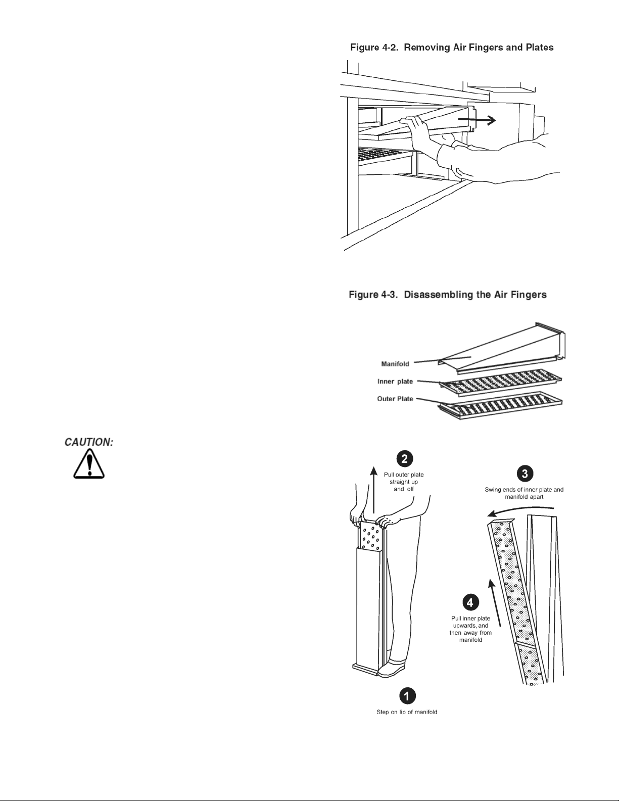
F. Slide the air fingers and blank plates out of the oven, as
shown in Figure 4-2. AS EACH FINGER OR PLATE IS
REMOVED, WRITE A “LOCATION CODE” ON IT WITH
A MARKER to make sure it can be reinstalled correctly.
Example of markings:
Top Row T1 T2 T3 T4
Bottom Row B1 B2 B3 B4
G.
Disassemble the air fingers as shown in Figure 4-3. AS
EACH FINGER IS DISASSEMBLED, WRITE THE
“LOCATION CODE” FOR THE FINGER ON ALL THREE
OF ITS PIECES. This will help you in correctly
reassembling the air fingers.
H. Clean the air finger components and the interior of the
baking chamber using a vacuum cleaner and a damp
cloth. Refer to the boxed warnings at the beginning of
this Section for cleaning precautions.
I. Reassemble the air fingers. Then replace them in the
oven, using the “location codes” as a guide.
J. Replace the end plugs on the oven.
K. Reassemble the conveyor into the oven. If the drive
sprocket was removed when installing the conveyor,
replace it at this time.
L. Reattach the drive chain.
M. Check the tension of the conveyor belt as shown in
Figure 2-14 (in Section 2, Installation). The belt should lift
between 3 and 4” (75-100mm) DO NOT OVERTIGHTEN
THE CONVEYOR BELT. If necessary, the belt tension
can be adjusted by turning the conveyor adjustment
screws, located at the idler (left) end of the conveyor
N. Replace the crumb trays.
Incorrect reassembly of the air fingers will
change the baking properties of the oven.
27
Page 32

III. MAINTENANCE – EVERY 3 MONTHS
A. Check that the oven is cool and the power is disconnected,
as described in the warning at the beginning of this Section.
B. Vacuum both of the blower mounts, and their surrounding
compartments, using a shop vacuum.
C. Tighten all electrical terminal screws.
D. Split Belt Disassembly and Cleaning
1. Refer to Part D, Conveyor Installation, in the
Installation section of this Manual. Then, remove
the following components from the oven:
• Conveyor end stop
• Crumb trays
• Chain cover
• Drive chains
• End plugs
• Conveyor assembly
2. Remove the master links from each conveyor belt.
Then, roll the belts up along the length of the
conveyor to remove them from the frame.
3. Remove the two conveyor adjustment screws from
the idler end of the conveyor frame, as shown in
Figure 4-4.
4. Remove the idler shaft assembly from the conveyor.
5. Pull apart the two sections of the idler shaft.
6. Clean the shafts thoroughly using a rag. Then,
lubricate both the extended shaft and the interior of
the hollow shaft using a light food-grade lubricant.
DO NOT lubricate the shafts using WD40 or a
similar product. This can cause the shafts to wear
rapidly.
7. Before reassembling the shafts into the conveyor
frame, check that they are oriented properly.
Figure 4-4. Disassembling the idler shaft
8. Reassemble the idler shaft into the conveyor.
Make sure that the bronze washer is in place
between the two sections of the shaft. See Figure
4-4.
9. Replace the conveyor adjustment screws as
shown in Figure 4-4. To allow the conveyor belt
to be reinstalled later, do not tighten the screws
at this time.
10. Loosen the set screw on both of the conveyor
drive sprockets. Then, remove the sprockets from
the shaft.
11. Check the conveyor configuration as follows:
High-speed conveyors are equipped with large
flange bearings at both ends of the shaft, as
shown in Figure 4-5. For these conveyors,
remove the two screws that hold each bearing to
the conveyor frame. With the screws removed, lift
the end of the shaft at the front of the oven, and
pull the entire assembly free of the conveyor
frame.
12. Standard conveyors are equipped with bronze
bushings mounted on spacers at both ends of the
shaft, as shown in Figure 4-5. For these conveyors, remove the two screws that hold the bracket
to the conveyor frame. With the screws removed,
lift the end of the shaft at the front of the oven,
and pull the entire assembly free of the conveyor
frame. The brackets will be removed along with
the drive shaft assembly.
13. Disassemble and lubricate the two sections of the
drive shaft as described for the idler shaft, above.
14. Before reassembling the shafts into the conveyor
frame, check that they are oriented properly.
15. Reassemble the drive shaft into the conveyor.
Make sure that the bronze washer is in place
between the two sections of the shaft. See Figure
4-4.
16. Replace the drive sprockets. Reassemble the
belts and master links onto the conveyor.
17. Reinstall the end plugs and conveyor onto the
oven. Reattach the drive chains. Replace the
chain cover.
18. Check the tension of the conveyor belt as shown
in Figure 2-14 (in Section 2, Installation). The belt
should lift about 1(25mm). If necessary, adjust
the belt tension by turning the conveyor
adjustment screws.
19.
Replace all components onto the oven.
Figure 4-5. Drive shaft configurations
28
Page 33

IV. MAINTENANCE - EVERY 6 MONTHS
A. Check that the oven is cool and the power is
disconnected, as described in the warning at the
beginning of this Section.
C. For gas ovens, inspect and clean the burner nozzle
and the spark electrode assembly.
D. Check the conveyor drive shaft bushings and
spacers. Replace the components if they are worn.
29
Page 34
1
2
3
4
5
6
7
13
19
8
14
20
9
15
21
10
16 17
22
11
12
18
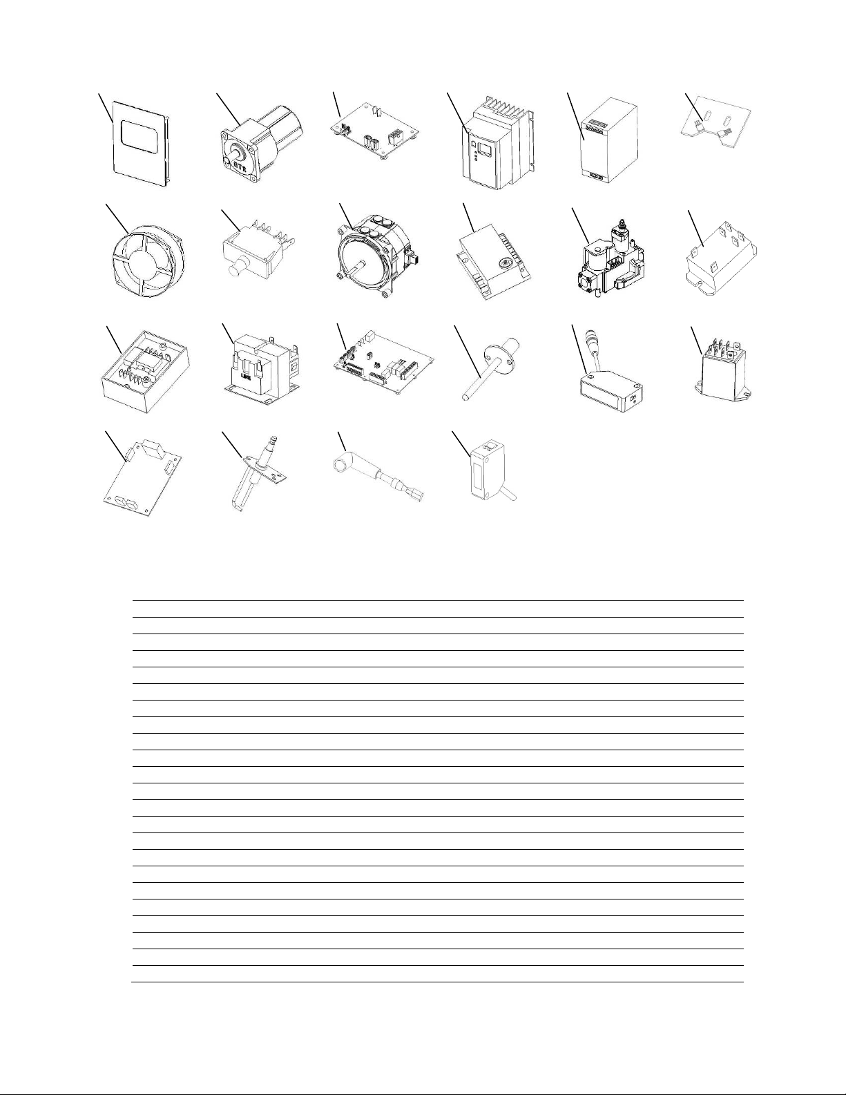
KEY SPARE PARTS PS360G GAS OVEN
ITEM QTY P/N DESCRIPTION
1 1 65564 Digital Display, Programmed
2 1 65756 Motor, Conveyor Drive
3 1 65566 Conveyor Control Board
4 1 69614 Inverter, 2 HP Lenze (230V Input)
5 1 69079 Power Supply, 24VDC, 120W
6 1 69583 Rotation Sensor (1 per motor)
7 1 36451 Fan,Cooling
8 2 63909 Switch, Door Interlock
9 1 69149 Blower Motor, 1/3 HP
10 1 61602 Ignition Module
11 1 60679 Gas Valve (Modulating) w/ flanges and cable
12 1 50794 Relay, 30A (240V coil)
13 1 33983 Hi Limit Thermostat
14 1 32108 Transformer, 240 primary / 24 secondary
15 1 65565 Board,Main – I/O
16 2 60520-2 Thermocouple, 2” Grounded (4 per oven)
17 1 60185 Photo Sensor
18 1 59132 Relay, DPDT 24VDC Coil
19 2 69582 Rotation Switch Board
20 1 62288 Igniter, Single Rod
21 1 62282 Ignition Cable
22 1 69472 Front Photo Eye (optional)
30
Page 35

SECTION 5 – WIRING DIAGRAMS
31
Page 36

32
Page 37

NOTES
33
Page 38

 Loading...