

Page 1
Gas PS360/PS360WB Tandem (AGA), English
A MIDDLEBY COMPANY
owner's operating
& installation manual
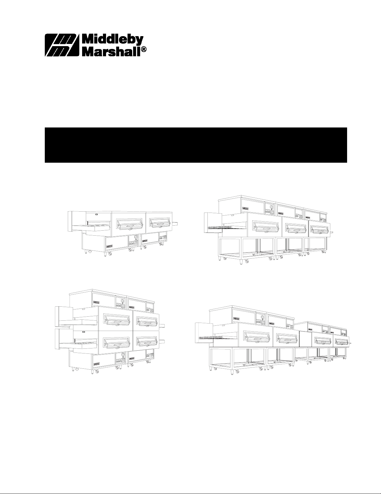
SERIES PS360/PS360WB
TANDEM GAS OVEN MODELS
PS360/PS360WB Tandem Oven
PS360/PS360WB Double Tandem Oven
© 1999 Middleby Marshall Inc.
PS360/PS360WB Tri Tandem Oven
PS360/PS360WB Quad Tandem Oven
P/N 39223
Rev. B V2 3/99
Price $30.00
Page 2

NOTICE:
This Operating and Installation Manual should be given to the user. The operator of the oven should be familiar
with the functions and operation of the oven.
This manual must be kept in a prominent, easily reachable location near the oven.
The oven has a combustion system suitable for use with all natural gases and can be converted by a qualified
service agent for use with liquified gas.
It is suggested to obtain a service contract with a manufacturer's certified service agent.
WARNING
POST, IN A PROMINENT LOCATION, THE EMERGENCY TELEPHONE NUMBER OF YOUR LOCAL GAS SUP-
PLIER AND INSTRUCTIONS TO BE FOLLOWED IN THE EVENT YOU SMELL GAS.
Instructions to be followed in the event the user smells gas shall be obtained by consulting the local gas supplier. If
the smell of gas is detected, immediately call the emergency phone number of your local Gas Company. They will
have personnel and provisions available to correct the problem.
FOR YOUR SAFETY
Do not store or use gasoline or other
flammable vapors or liquids in the
vicinity of this or any other appliance.
WARNING:
Improper installation, adjustment, alteration, service or
maintenance can cause property damage, injury or
death. Read the installation, operating and maintenance
instructions thoroughly before installing or servicing
this equipment.
NOTICE
CONTACT YOUR LOCAL SERVICE COMPANY TO PERFORM MAINTENANCE AND REPAIRS.
A SERVICE AGENT DIRECTORY IS SUPPLIED IN YOUR INSTALLATION KIT.
NOTICE
Using any parts other than genuine Middleby Marshall factory
manufactured parts relieves the manufacturer of all warranty and liability.
NOTICE
Middleby Marshall (Manufacturer) reserves the right to
change specifications at any time.
NOTICE
The equipment warranty is not valid unless the oven is installed, started and demonstrated under
the supervision of a factory certified installer.
Retain This Manual For Future Reference
Middleby Marshall Inc. 1400 Toastmaster Drive Elgin, IL 60120 USA (847) 741-3300 FAX (847) 741-4406
Middleby Corporation Service Hotline 1-800-238-8444
www.middleby.com
i
Page 3

MIDDLEBY MARSHALL INC.
NO QUIBBLE LIMITED WARRANTY
(U.S.A. ONLY)
MIDDLEBY MARSHALL INC.
OVEN LIMITED WARRANTY
(Non U.S.A.)
MIDDLEBY MARSHALL, HEREINAFTER REFERRED TO
AS THE SELLER, WARRANTS EQUIPMENT MANUFACTURED BY IT TO BE FREE FROM DEFECTS IN MATERIAL
AND WORKMANSHIP FOR WHICH IT IS RESPONSIBLE.
THE SELLERS OBLIGATION UNDER THIS WARRANTY
SHALL BE LIMITED TO REPLACING OR REPAIRING AT
SELLERS OPTION, WITHOUT CHARGE, ANY PART FOUND
TO BE DEFECTIVE AND ANY LABOR AND MATERIAL EXPENSE INCURRED BY SELLER IN REPAIRING OR REPLACING SUCH PART, SUCH WARRANTY SHALL BE
LIMITED TO THE ORIGINAL PURCHASER ONLY AND
SHALL BE EFFECTIVE FOR A PERIOD OF ONE YEAR
FROM DATE OF ORIGINAL INSTALLATION, OR 18 MONTHS
FROM DATE OF SHIPMENT, WHICHEVER IS EARLIER;
PROVIDED THAT TERMS OF PAYMENT HAVE BEEN FULLY
MET.
This warranty is valid only if the equipment is installed,
started and demonstrated under the supervision of a factory
certified installer.
Normal maintenance functions, including lubrication, cleaning or customer abuse are not covered by this no quibble
warranty.
Seller shall be responsible only for repairs or replacements
of defective parts performed by Sellers authorized service
personnel. Authorized service agencies are located in principal cities throughout the contiguous United States, Alaska
and Hawaii. This warranty is valid in the 50 United States and
is void elsewhere unless the product is purchased through
Middleby International with warranty included.
The foregoing warranty is exclusive and in lieu of all other
warranties, expressed or implied. There are no implied
warranties of merchantability or of fitness for a particular
purpose.
The foregoing warranty shall be Seller's sole and exclusive
obligation and Buyer's sole and exclusive remedy for any
action including breach of contract or negligence. In no event
shall Seller be liable for a sum in excess of the purchase
price of the item. Seller shall not be liable for any prospective
or lost profits of Buyer.
The seller warrants equipment manufactured by it to be free
from defects in material and workmanship for which it is
responsible. The Sellers obligation under this warranty
shall be limited to replacing or repairing at Sellers option,
without charge, F.O.B. Sellers factory, any part found to be
defective and any labor and material expense incurred by
Seller in repairing or replacing such part, such warranty to
be limited to a period of one year from date of original
installation or 15 months from date of shipment from Sellers
factory, whichever is earlier, provided that terms of payment
have been fully met. All labor shall be performed during
regular working hours. Overtime premium will be charged
to the Buyer.
This warranty is not valid unless equipment is installed,
started, and demonstrated under the supervision of a
factory certified installer.
Normal maintenance functions, including lubrication, adjustment of airflow, thermostats, door mechanisms,
microswitches, burners and pilot burners and replacement
of light bulbs, fuses and indicating lights, are not covered by
warranty.
Any repairs or replacements of defective parts shall be
performed by Sellers authorized service personnel. Seller
shall not be responsible for any costs incurred if the work is
performed by other than Sellers authorized service personnel.
When returning any part under warranty, the part must be
intact and complete, without evidence of misuse or abuse,
freight prepaid.
Seller shall not be liable for consequential damages of any
kind which occur during the course of installation of equipment, or which result from the use or misuse by Buyer, its
employees or others of the equipment supplied hereunder,
and Buyers sole and exclusive remedy against Seller for
any breach of the foregoing warranty or otherwise shall be
for the repair or replacement of the equipment or parts
thereof affected by such breach.
The foregoing warranty shall be valid and binding upon
Seller if and only if Buyer loads, operates and maintains the
equipment supplied hereunder in accordance with the
instruction manual provided to Buyer. Seller does not guarantee the process of manufacture by Buyer or the quality of
product to be produced by the equipment supplied hereunder and Seller shall not be liable for any prospective or lost
profits of Buyer.
THE FOREGOING WARRANTY IS EXCLUSIVE AND IN LIEU
OF ALL OTHER EXPRESS AND IMPLIED WARRANTIES
WHATSOEVER. SPECIFICALLY THERE ARE NO IMPLIED
WARRANTIES OF MERCHANTABILITY OR OF FITNESS
FOR A PARTICULAR PURPOSE.
The foregoing shall be Sellers sole and exclusive obligation and Buyers sole and exclusive remedy for any action,
whether in breach of contract or negligence. In no event shall
seller be liable for a sum in excess of the purchase price of
the item.
ii
Page 4

TABLE OF CONTENTS
page
SECTION 1 - DESCRIPTION ................................................. 1-1
I. OVEN SPECIFICATIONS .................................... 1-1
A. Physical Specifications ................................. 1-1
B. General Specifications .................................. 1-1
C. Electrical Specifications ................................ 1-1
D. Gas Orifice and Pressure Specifications ........ 1-1
II. OVEN USES ....................................................... 1-2
III. OVEN COMPONENTS ........................................ 1-2
A. Conveyor Drive Motor .................................... 1-2
B. Air Fingers .................................................... 1-2
C. Conveyor ...................................................... 1-2
D. Window ........................................................ 1-2
E. Oven Data Plate ............................................ 1-2
F. Crumb Pans .................................................. 1-2
G. Control Panel ................................................ 1-2
H. Machinery Compartment Access Panel .......... 1-2
I. End Panels ................................................... 1-2
J. Conveyor End Stop ....................................... 1-2
K. Conveyor Extension Covers .......................... 1-2
L. Gas Burner ................................................... 1-2
M. Blowers ........................................................ 1-2
N. Cooling Fans ................................................. 1-2
page
SECTION 3 - OPERATION .................................................... 3-1
I. LOCATION AND DESCRIPTION OF CONTROLS 3-1
A. BLOWER Switch .......................................... 3-1
B. HEAT Switch ................................................ 3-1
C. CONVEYOR Switch ...................................... 3-1
D. Digital Temperature Controller ....................... 3-1
E. Conveyor Speed Display ............................... 3-1
F. Conveyor Speed Adjustment Knob ................. 3-1
G. Conveyor Speed Controller ............................ 3-1
H. Machinery Cpt. Access Panel Safety Switch .. 3-1
II. NORMAL OPERATION, STEP-BY-STEP ............ 3-2
A. Daily Startup Procedures ............................... 3-2
B. Daily Shutdown Procedures ........................... 3-2
III. QUICK REFERENCE: BAKE TIME ...................... 3-3
IV. QUICK REFERENCE: DIGITAL TEMP CONTROL 3-3
V. QUICK REFERENCE: TROUBLESHOOTING ...... 3-4
SECTION 4 - MAINTENANCE ............................................... 4-1
I. MAINTENANCE - DAILY ...................................... 4-2
II. MAINTENANCE - MONTHLY ............................... 4-3
III. MAINTENANCE - EVERY 3 MONTHS ................. 4-4
IV. MAINTENANCE - EVERY 6 MONTHS ................. 4-4
SECTION 2 - INSTALLATION ............................................... 2-1
I. INSTALLATION KIT ............................................. 2-2
II. TRANSITION CHAMBER COMPONENTS ........... 2-2
III. VENTILATION SYSTEM ...................................... 2-3
A. Requirements ................................................ 2-3
B. Recommendations ......................................... 2-3
C. Other Ventilation Concerns ............................ 2-3
IV. THERMOCOUPLE INSTALLATION ...................... 2-4
V. ASSEMBLY ......................................................... 2-5
A. Oven Stand ................................................... 2-5
B. Joining the Oven Bodies ................................ 2-5
C. Installing the Center Transition ....................... 2-7
D. Installing the Conveyor Frame and Belt ........... 2-9
VI. ELECTRICAL SUPPLY ....................................... 2-12
VII. GAS SUPPLY .................................................... 2-13
A. Connection ................................................... 2-13
B. Gas Conversion ........................................... 2-14
SECTION 5 - ELECTRICAL SCHEMATICS ............................ 4-1
I. WIRING DIAGRAM, PS360/PS360WB
Tandem & Double Tandem Ovens ......................... 4-1
II. WIRING DIAGRAM, PS360/PS360WB
Tri Tandem & Quad Tandem Ovens ....................... 4-2
iii
Page 5

SECTION 1
DESCRIPTION
SECTION 1
DESCRIPTION
I. OVEN SPECIFICATIONS
A. PHYSICAL SPECIFICATIONS
Tandem Double Tandem Tri Tandem Quad Tandem
PS360 PS360WB PS360 PS360WB PS360 PS360WB PS360 PS360WB
Dimensions:
Overall Height (inc. top) 45-1/2 45-1/2 81-1/2 81-1/2 64-1/2 64-1/2 64-1/2 64-1/2
Overall Depth (inc. motor 52 60 52 60 52 60 52 60
shroud and window) 1321mm 1524mm 1321mm 1524mm 1321mm 1524mm 1321mm 1524mm
Overall Depth (inc. motor 49 57 49 57 49 57 49 57
shroud - no window) 1245mm 1448mm 1245mm 1448mm 1245mm 1448mm 1245mm 1448mm
Overall Length 144-1/2 144-1/2 144-1/2 144-1/2 199 199 273-1/2 273-1/2
Conveyor Width 32 40 32 40 32 40 32 40
Recommended Minimum
Clearances:
Rear of Oven (inc. motor 1 1 1 1 1 1 1 1
shroud) to Wall 25mm 25mm 25mm 25mm 25mm 25mm 25mm 25mm
Conveyor Extension to Wall 0 0 0 0 0 0 0 0
(both ends) 0mm 0mm 0mm 0mm 0mm 0mm 0mm 0mm
1156mm 1156mm 2070mm 2070mm 1638mm 1638mm 1638mm 1638mm
3670mm 3670mm 3670mm 3670mm 5055mm 5055mm 6947mm 6947mm
813mm 1016mm 813mm 1016mm 813mm 1016mm 813mm 1016mm
B. GENERAL SPECIFICATIONS (per oven section)
PS360 PS360WB
Weight 1350 lbs. (612kg) 1400 lbs. (634kg)
Shipping Weight 1675 lbs. (760 kg) 1750 lbs. (780kg)
Shipping Cube Approx. 104.5 ft3 (3.0 m3) Approx. 122 ft.3 (3.5m3)
Rated Heat Input 135,000 BTU (34,020 kcal, 40 kW/hr) 170,000 BTU (42,840 kcal, 50 kW/hr)
Maximum Operating Temperature 550°F (288°C)
Air Blowers Two blowers at 1550 ft.3/min. (43.9m3/min.) at 1700 rpm
Average Air Jet Velocity 2600 ft./min. (1320cm/sec.)
Warmup Time 15 min.
Flue Vent 1.08" (27mm) D x 3" (76mm) W
Exhaust Flow 80 ft.3/min. (2.1 m3/min.)
0.88 (2.2cm) Water Static Pressure
C. ELECTRICAL SPECIFICATIONS (per oven section)
Main Blower Voltage Control Circuit Voltage Phase Freq Current Draw Poles Wires
208-240V 120V 1 Ph 50/60Hz 8A 3 Pole 4 Wire (2 hot, 1 neut, 1 gd)
190/200/208/220/380V (export)
110V (transformer) 1 Ph 50Hz 8 A 2 Pole 3 Wire (2 hot, 1 gd)
D. GAS ORIFICE AND PRESSURE SPECIFICATIONS (per oven section)
Gas Type Main Orifice I.D. Main Orifice I.D. Pilot Orifice Bypass Orifice Supply (Inlet) Orifice (Manifold)
(PS360) (PS360WB) I.D. I.D. Pressure Pressure
Natural 0.219 0.250 0.028 0.065/#53 drill 6-12 W.C. 3.5 W.C.
Propane 0.134 0.152 0.018 0.034/#62 drill 11-14 W.C. 10 W.C.
(5.56mm) (6.35mm) (0.71mm) (1.65mm) (14.9-29.9mbar) (8.7mbar)
(3.40mm) (3.86mm) (0.46mm) (0.86mm) (27.4-34.9mbar) (24.9mbar)
1-1
Page 6
SECTION 1
DESCRIPTION
II. OVEN USES
PS360/PS360WB Tandem Ovens can be used to
bake and/or cook a wide variety of food products, such
as pizza, pizza-type products, cookies, sandwiches
and others.
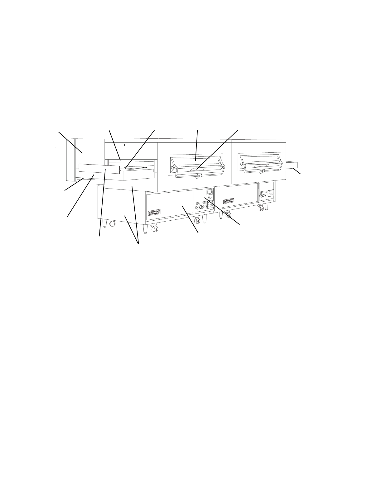
III. OVEN COMPONENTS
A. Conveyor
Drive Motor
(inside shroud)
L. Crumb Pan
K. Conveyor
Extension
Covers
B. Air Fingers
(inside baking
chamber)
J. Conveyor
End Stop
D. Front
C. Conveyor
I. End Panels
Loading
Window
H. Machinery
Compartment
Access Panel
Figure 1-1 - Oven Components
E. Oven Data
Plate
F. Crumb Pan
G. Control
Panel
A. Conveyor Drive Motor: Moves the conveyor.
B. Air Fingers: Project streams of hot air onto the food
product.
C. Conveyor: Moves the food product through the oven.
D. Window (on ovens so equipped): Allows the user
to see and access food products inside the baking
chamber.
E. Oven Data Plate: Provides specifications for the
oven that affect installation and operation. Refer to
Section 2, Installation, for details.
F. Crumb Pans: Catch crumbs and other material that
drop through the conveyor belt. One crumb pan is
located at each end of the conveyor.
G. Control Panel: Location of the operating controls for
the oven. Refer to Section 3, Operation, for details.
H. Machinery Compartment Access Panel: Allows
access to the oven's interior components. No userservicable parts are located in the machinery compartment.
I. End Panels: Allow access to the oven's interior
components. No user-servicable parts are located
inside the end panels.
J. Conveyor End Stop (not present on ovens with
heavy-duty conveyor): Prevents food products from
falling off the end of the moving conveyor.
K. Conveyor Extension Covers (not present on ov-
ens with heavy-duty conveyor): Cover the ends of
the conveyor frame. One cover is located at each end
of the conveyor.
Not Shown:
L. Gas Burner: Heats air, which is then projected to the
air fingers by the blowers. The burner is turned on and
off according to the settings on the Digital Temperature
Controller (located on the Control Panel).
M. Blowers: Fans that project hot air from the burner to
the air fingers.
N. Cooling Fans: Cool the interior of the oven to protect
the components.
1-2
Page 7

SECTION 2
INSTALLATION
SECTION 2
INSTALLATION
WARNING
Do not obstruct the flow of combustion and ventilation air to and from your oven. There must be no
obstructions around or underneath the oven.
CAUTION
For additional installation information, refer to the PS360 Pre-Installation Procedures Manual (Middleby
Marshall P/N 88210-0024) or contact your local Authorized Service Agent.
NOTE
There must be adequate clearance between the oven and combustible construction. Clearance must
also be provided for servicing and for operation.
NOTE
Wiring diagrams are contained in this manual (Section 5, Electrical Schematics) and are also
located inside the Machinery Compartment Access Panel.
NOTE
All aspects of the oven installation, including placement, utility connections, and ventilation requirements, must
conform with any applicable local and national codes. These codes supercede the requirements and guidelines
provided in this manual.
NOTE
In U.S.A., the oven installation must conform with local codes, or in the absence of local codes, with the National
Fuel Gas Code, ANSI Z223.1. The oven, when installed, must be electrically grounded in accordance with local
codes, or in the absence of local codes, with the National Electrical Code (NEC), or ANSI/NFPA70.
NOTE
In Canada, the oven installation must conform with local codes, or in the absence of local codes, with the Natural
Gas Installation Code, CAN/CGA-B149.1, or the Propane Gas Installation Code, CAN/CGA-B149.2, as applicable.
The oven, when installed, must be electrically grounded in accordance with local codes, or in the absence of local
codes, with the Canadian Electrical Code CSA, C22.2, as applicable.
NOTE
For Australian installation, the oven installation must conform with AGA Code, AG601, and with any requirements of
the appropriate statutory authority.
2-1
Page 8
SECTION 2
INSTALLATION
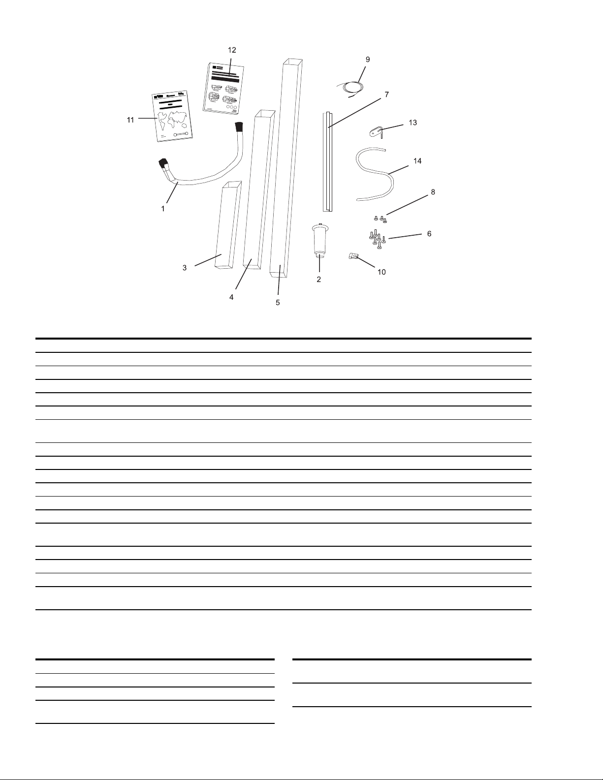
I. INSTALLATION KIT
Fig. 2-1 - Installation Kit
Item Part # Description Tandem Double Tandem Tri Tandem Quad Tandem
1 22361-0001 Flexible Gas Hose 2434
2 22450-0028 Adjustable Legs 8 8 12 16
3 30773 Flue Vent, 14"Lg. 2 - - 4 30759 Flue Vent, 29-1/2"Lg. - 2 3 4
5 30758 Flue Vent, 50" Lg. - 2 - 6 21256-0008 Screw, 10-32 x 3/8 A/R A/R A/R A/R
7 35000-1103 Conveyor End Stop - PS360 1 2 - -
35000-1899 Conveyor End Stop - PS360WB
8 21292-0001 Scr, #2PT 10-16 x 3/4 Hx Wsh A/R A/R A/R A/R
9 33984 Thermocouple 2434
10 27276-0001 Cable Clamp 2434
11 1002040 Warranty, Parts & Serv. Dist.List 1111
12 39223 Owners Operating and Installation Manual (English) 1111
13 27126-0238 11 Piece Hex Key Set 1111
14 31389 Silicone Tubing, 36 (914mm) L x 2434
- 35000-1454
- 35000-1456 Front Gasket Spacer 2444
- 35000-1457 Rear Gasket Spacer 2444
- 37200-0013
32483
5/16 (8mm) ID x 7/16 (11mm) OD
Machinery Compartment Trim Strip
Baking Chamber Gasket and Frame - PS360
Baking Chamber Gasket and Frame - PS360WB
1222
1222
II. TRANSITION CHAMBER COMPONENTS (Quad Tandem Ovens Only)
Qty. Part # Description
1 48009-0025 Side Wall
1 35000-1748 Rear Support
2 35000-1749 Front Support
2 37000-0697 Top Support Channel - PS360
32455 Top Support Channel - PS360WB
Qty. Part # Description
1 37000-0696 Floor Panel - PS360
32457 Floor Panel - PS360WB
1 48009-0024 Top Panel - PS360
32456 Top Panel - PS360WB
2-2
Page 9
III. VENTILATION SYSTEM
IMPORTANT
Where national or local codes require
the installation of fire suppression
equipment or other supplementary
equipment, DO NOT mount the equip-
ment directly to the oven.
MOUNTING SUCH EQUIPMENT ON
THE OVEN MAY:
VOID AGENCY CERTIFICATIONS
RESTRICT SERVICE ACCESS
LEAD TO INCREASED SERVICE
EXPENSES FOR THE OWNER
A. REQUIREMENTS
A mechanically driven ventilation system is required for the
oven.
PROPER VENTILATION OF THE OVEN IS THE
RESPONSIBILITY OF THE OWNER.
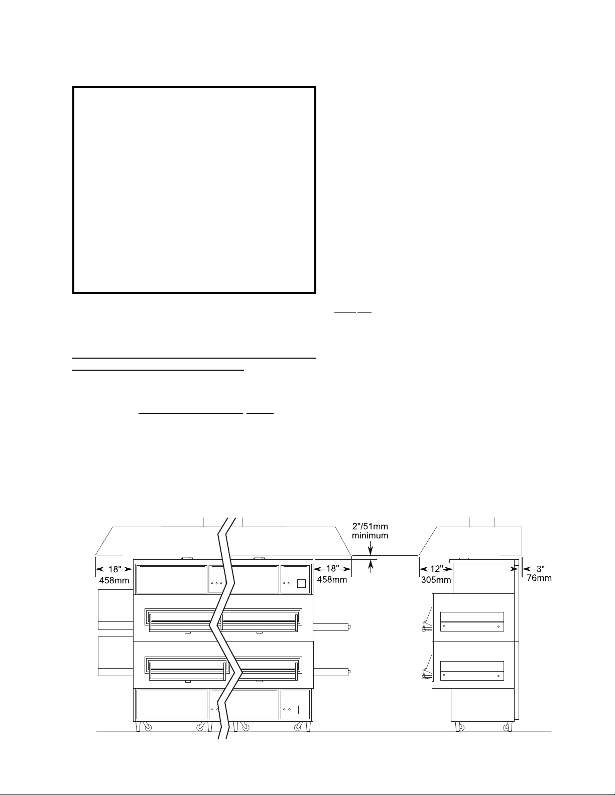
B. RECOMMENDATIONS
NOTE THAT THE HOOD DIMENSIONS SHOWN IN FIGURE 2-2 ARE RECOMMENDATIONS ONLY. LOCAL
AND NATIONAL CODES WILL VARY, AND MUST BE
FOLLOWED WHEN INSTALLING THE VENTILATION
SYSTEM. ANY APPLICABLE LOCAL AND NATIONAL
CODES SUPERSEDE THE RECOMMENDATIONS
SHOWN IN THIS MANUAL.
SECTION 2
INSTALLATION
The rate of air flow exhausted through the ventilation
system may vary depending on the oven configuration and
hood design. Consult the hood manufacturer or ventilation
engineer for these specifications.
To avoid a negative pressure condition in the kitchen area,
return air must be brought back to replenish the air that was
exhausted. A negative pressure in the kitchen can cause
heat- related problems to the oven components as if there
were no ventilation at all. The best method of supplying
return air is through the heating, ventilation and air
conditioning (HVAC) system. Through the HVAC system,
the air can be temperature-controlled for summer and
winter. Return air can also be brought in directly from
outside the building, but detrimental effects can result from
extreme seasonal hot and cold temperatures from the
outdoors.
NOTE: Return air from the mechanically driven system
must not blow at the opening of the baking chamber. Poor
oven baking performance will result.
C. OTHER VENTILATION CONCERNS
Special locations, conditions, or problems may re-
quire the services of a ventilation engineer or special-
ist.
Inadequate ventilation can inhibit oven performance.
It is recommended that the ventilation system and
duct work be checked at prevailing intervals as speci-
fied by the hood manufacturer and/or HVAC engineer
or specialist.
Fig. 2-2 - Ventilation System
2-3
Page 10
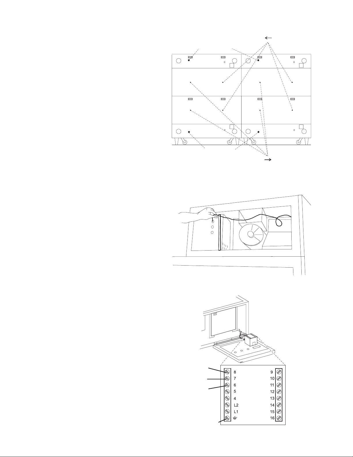
IV.
THERMOCOUPLE
INSTALLATION
1. Install the thermocouple sensing bulb into the correct
hole in the rear of the oven, as shown in Figure 2-3.
2. Thread the thermocouple lead through the grommet
and into the machinery compartment.
Thread lead into
machinery
compartment here
Thread lead into
machinery
compartment here
Use for conveyor
Use for conveyor
Figure 2-3
Thermocouple Installation Locations
3. Remove the right-side access panel of the machinery
compartment.
4. Thread the thermocouple lead through the side of the
machinery compartment as shown in Figure 2-4, and
into the electrical box (at the right-front of the machinery compartment).
5. Connect the thermocouple leads to the temperature
controller as shown in Figure 2-5.
6. Repeat Steps 1-5 for each of the other oven sections in
the installation.
Figure 2-4
Placing the Thermocouple Leads
Figure 2-5
Thermocouple Lead
Connections
8=White=Positive
7=Red=Negative
R=No Connection
Ground=Shielded cable
Page 11

V. ASSEMBLY
A. OVEN STAND
If the installation includes upper ovens
mounted atop lower ovens, the ovens
must be stacked before joining the
tandem ovens together.
If the installation includes ovens that
are to be mounted on stands, assemble
the ovens to the stands before joining
the ovens together. An exploded view
of the stand is shown in Figure 2-6.
B. JOINING THE OVEN BODIES
Attachment
plates inc. w/
upper oven
Figure 2-6
Exploded View -
Oven Stand
For TANDEM and DOUBLE TANDEM installations, perform
Steps 1-8 in this section to join the ovens.
For TRI TANDEM installations, perform Steps 1-8 to join
two of the ovens together, and ensure that they are level;
then, repeat Steps 1-8 to join the third oven to the two that
have already been assembled.
For QUAD TANDEM installations, perform Steps 1-8 for
1. Determine the proper position of the ovens by referring
to Figure 2-7. Then, move the ovens to their approximate
final locations.
2. Check that the top and bottom air finger retaining
screws are present on all mating ends of the oven
sections. See Figure 2-7. The screws prevent the air
fingers from sliding in between the oven sections.
EACH PAIR of ovens, producing two sets of two joined
ovens. Do not assemble the center bridge section at this
time.
Figure 2-7
LEFT OVEN RIGHT OVEN
Oven Positioning and Alignment
Alignment
plate
Slot for
alignment
plate
Air finger
retaining
screws
Sealing gasket
assembly (pre-
mounted)
NOTE: The Sealing Gasket Assembly may be
pre-mounted to EITHER of the two ovens.
Page 12

SECTION 2
INSTALLATION
3. Remove the rear axial cooling fans that are adjacent to
the mating sides of the ovens. The fans may either be
completely disconnected, or left attached by their
wiring as shown in Figure 2-8.
4. Insert three of the supplied 1/2 x 5 bolts through the
holes in the frame of the right oven, pointing outward as
shown in Figure 2-9. Then, slide the spacers into place
on the bolts.
Mating surface of
ovens (shown from
lower rear)
Wiring is still
connected
Figure 2-8 - Cooling Fan Removal
2-1/2 x 2-1/2
(64 x 64mm)
spacers
5. Push the ovens together. Check that the mounting
bolts, alignment plate, and sealing gasket are all
properly aligned. See Figure 2-10.
6. Tighten all of the attaching bolts. Check that the
mating edges of the ovens align properly. If gaps
appear between the tops of the ovens, it will be
necessary to loosen the connecting bolts and realign
the ovens.
Bolts
2-1/2 x 8
(64 x 203mm)
spacers
Figure 2-9 - Bolts and Spacers
2-6
Figure 2-10 - Aligning the Sections
Page 13

SECTION 2
INSTALLATION
7. Attach the front trim strip between the two ovens, as
shown in Figure 2-11.
8. Replace the rear axial cooling fans. See Figure 2-8.
9. Perform one of the following, as appropriate:
For PS360/360WB Tandem and Double Tandem
installations, skip ahead to Part D, INSTALLING
THE CONVEYOR FRAME AND BELT (Page 2-9).
For PS360/360WB Tri Tandem installations, perform
Steps 1-8 again to attach the third oven to the two
that have just been assembled. Then, skip ahead to
Part D, INSTALLING THE CONVEYOR FRAME
AND BELT (Page 2-9).
For PS360/360WB Quad Tandem installations,
perform Steps 1-8 again to attach the two remaining
ovens to each other. Then, continue on to Part C,
INSTALLING THE CENTER TRANSITION.
C. INSTALLING THE CENTER TRANSITION
1. Install the upper support channels to the two center
ovens as shown in Figures 2-12 and 2-13.
Figure 2-11 - Trim Strip Installation
Trim strip
Figure 2-12
Support Channel Installation - Lower Oven
Support
channels
2-7
Figure 2-13
Support Channel Installation - Upper Oven
Support
channels
Page 14

SECTION 2
INSTALLATION
2. Align the two center ovens so that they are level and
20 (508mm) apart. Then, attach the two angled
support brackets between the two center ovens, as
shown in Figures 2-14 and 2-15.
Note that a LOWER OVEN uses different support
brackets for the front and rear, while an UPPER OVEN
uses identical brackets on the front and rear.
Figure 2-14
Support Brackets,
Lower Oven
Upper surfaces of
brackets must be level
with each other
Figure 2-15
Support Brackets,
Upper Oven
20
508mm
4. Place the transition floor panel into place atop the
support brackets. See Figure 2-16.
5. Install the transition (center) conveyor section, as
shown in Figure 2-17. Align the conveyor section so
that it extends the same distance into the two oven
chambers.
20
508mm
Figure 2-16
Floor Panel
Installation
Figure 2-17
Installing
the Frame
2-8
Page 15

D. INSTALLING THE CONVEYOR FRAME AND BELT
FOR ALL TYPES OF OVENS, ENSURE THAT THE
DRIVE SECTION/END OF THE CONVEYOR FRAME IS
PLACED ON THE SAME END OF THE OVEN AS THE
CONVEYOR DRIVE MOTOR.
1. Insert the conveyor frame into the oven as follows:
SECTION 2
INSTALLATION
For a TANDEM or DOUBLE TANDEM oven,
slide one hinged conveyor frame section
into each end of the oven. The two
sections butt against each other at the
gap between the two oven sections. See
Figure 2-18.
For TRI TANDEM ovens, slide one intermediate
frame section into the oven (from either end).
Center this section inside the oven.
Then, slide one intermediate
section and one end section of
the frame into EACH END of the
oven. All five sections should
butt against each other. See
Figure 2-19.
Hinged
end section
End
section
Hinged
end section
Figure 2-18
Tandem and Double Tandem
Conveyor Installation
End
section
Intermediate
sections
Figure 2-19
Tri Tandem Conveyor
Installation
For QUAD TANDEM ovens, slide two intermediate
sections and one end section of the frame into EACH
END of the oven. Butt the two inner intermediate
sections against the transition (center) frame
section. The other frame sections
should butt against each other.
See Figure 2-20.
End
section
2-9
Intermediate
sections
End
section
Intermediate
sections
Center section
(transition)
Figure 2-20
Quad Tandem Conveyor Installation
Page 16

SECTION 2
INSTALLATION
2. Slide the conveyor belt through the support rods
underneath the frame, and thread it through the oven.
Then, reach through the oven window and pull the free
end of the belt through the oven so that it lies atop the
conveyor frame.
After the belt has been pulled through the oven, check
the following:
The conveyor belt links must be oriented as shown
in Figure 2-21.
The smooth side of the conveyor belt must face
UP.
3. Connect the inside master links. Check that the links
are oriented as shown in Figure 2-22.
Direction
of travel
Figure 2-21 - Conveyor Link Orientation
Incorrect
position
Correct
position
4. Connect the outside master links. Note that the
outside master links have right and left sides. The
right-side master link has an open hook facing you, as
shown in Figure 2-23.
Figure 2-22 - Inside Master Links
Direction
of travel
Figure 2-23
Outside Master
Links
2-10
Page 17

5. For a TANDEM, DOUBLE TANDEM, or TRI TANDEM
oven installation, skip ahead to Step 9. For a QUAD
TANDEM oven installation, continue on to Step 6.
6. Slide the top transition panel into place. Then, slide
the two transition side panels into place. See Figure
2-24.
7. If the four latches are not already attached to the side
and top transition panels, attach them in place as
shown in Figure 2-24.
8. Fasten the latches on the side and top panels to hold
the panels in place.
SECTION 2
INSTALLATION
Latches
Latches
Figure 2-24 - Transition Section Final Assembly
9. LOOSELY attach the conveyor drive motor to the end
wall of the oven, as shown in Figure 2-25.
10. Assemble the conveyor drive chain in place on the
motor and conveyor drive sprockets.
11. Position the motor to adjust the tension of the drive
chain. The deflection of the chain should be 3/4
(19mm). DO NOT OVERTIGHTEN THE DRIVE CHAIN.
Then, tighten the motor in place.
12. Assemble the end plugs and motor housing onto the
oven.
13. TANDEM AND DOUBLE TANDEM OVENS ONLY:
Assemble the end stops, conveyor crumb trays, and
conveyor extension covers onto the oven. These
components are illustrated in Figure 1-1 (Page 1-2).
Figure 2-25
Conveyor Motor and Drive Chain Assembly
2-11
Page 18

SECTION 2
INSTALLATION
VI. ELECTRICAL SUPPLY
WARNING
Authorized supplier personnel normally accomplish the
connections for the ventilation system, electric supply,
and gas supply, as arranged by the customer. Following
these connections, the factory-authorized installer can
perform the initial startup of the oven.
NOTE: The electric supply installation must satisfy the
requirements of the appropriate statutory authority, such
as the National Electrical Code (NEC), ANSI/NFPA70,
(U.S.A.); the Canadian Electrical Code, CSA C22.2; the
Australian Code AG601; or other applicable regulations.
NOTE: The electric supply connection must meet all
national and local electrical code requirements.
Check the oven data plate before making any electric
supply connections. Electric supply connections must
agree with data on the oven data plate. See Figure 2-26.
A fused disconnect switch or a main circuit breaker
(customer furnished) MUST be installed in the electric
supply line for each oven. It is recommended that this
switch/circuit breaker have lockout/tagout capability.
The supply conductors must be of the size (#14 AWG,
copper) recommended. Refer to the wiring diagrams in
Section 5 of this manual.
All gas oven electric supply connections are made via the
electrical junction box on the rear of the oven, shown in
Figure 2-27. The power lines then connect to the oven
circuits through the Machinery Compartment Access
Panel Safety Switch. This switch interrupts electric power
to the oven when the Machinery Compartment Access
Panel is opened.
CAUTION
Before connecting incoming power to the oven, measure
the voltage of each input leg to neutral. The expected
voltage is approximately 120V. ANY voltage reading
exceeding 130V indicates that the supply has a high leg.
CONNECTING A HIGH LEG TO THE OVEN VOIDS ALL
OVEN WARRANTIES. Connecting a high leg to the
black lead of the oven can severely damage the ovens
electrical and electronic components.
CAUTION
DO NOT CONNECT BLACK WIRE TO
HIGH LEG. VOLTAGE OF THE BLACK
AND WHITE WIRES MUST BE NO
HIGHER THAN 130 VAC
FOR DOMESTIC OVENS (WITHOUT EXTERNAL
TRANSFORMERS):
In the junction box on the rear of the oven, connect one
208 - 240V supply line to the black wire and the other
208 - 240V supply line to the red wire. Connect the
electric supply ground wire to the oven ground screw
located in the junction box. If necessary, have the
electrician supply the ground wire. Do NOT use the
wiring conduit or other piping for ground connections!
FOR EXPORT OVENS (WITH EXTERNAL
TRANSFORMERS):
First, position the transformer on the LEFT REAR wall
of the oven (as space permits), and fasten it in place
using the supplied mounting hardware.
Figure 2-26
Oven Data Plate
Then, refer to the appropriate wiring diagram in Section
5 of this manual to determine the correct transformer
connections for the supply lines. Connect the electric
supply ground wire to the oven ground screw located
in the junction box. If necessary, have the electrician
supply the ground wire. Do NOT use the wiring conduit
or other piping for ground connections!
2-12
Page 19

VII. GAS SUPPLY
CAUTION
DURING PRESSURE TESTING NOTE ONE OF
THE FOLLOWING:
1. The oven and its individual shutoff valve must
be disconnected from the gas supply piping
system during any pressure testing of that system
at test pressure in excess of 1/2 psi (3.45 kPa).
2. The oven must be isolated from the gas supply
piping system by closing its individual manual
shutoff valve during any pressure testing of the
gas supply piping system at test pressure equal to
or less than 1/2 psi (3.45 kPa).
3. If incoming pressure is over14 W.C. (35mbar),
a separate regulator MUST be installed in the line
BEFORE the individual shutoff valve for the oven.
WARNING: To prevent damage to the
control valve regulator during initial turn-
on of gas, it is very important to open the
manual shutoff valve very slowly.
After the initial gas turn-on, the manual shutoff
valve must remain open except during pressure
testing as outlined in the above steps or when
necessary during service maintenance.
SECTION 2
INSTALLATION
A. CONNECTION
Check the ovens gas supply requirements before making
the gas utility connection. Gas supply requirements are
listed on the ovens data plate (Figure 2-26) and in the Oven
Specifications table (Page 1-1 of this manual).
Check the oven data plate (see Figure 2-26) to determine
the type of gas (Propane or Natural) to be used with the
oven.
Refer to the instructions in the gas hose package (included
in the Base Pad Kit) before connecting the gas line. One
gas line connection method is shown in Figure 2-28;
however, compliance with the applicable standards and
regulations is mandatory.
Inlet, regulated, and pilot gas pressure readings can be
taken using a U tube manometer at the tap locations
shown in Figure 2-29.
One 90° elbow equals a 4 (1.22m) length of pipe. The
recommended pipe sizes are larger than usually required
to eliminate any operation problems. It is much less
expensive to make the initial installment large enough to do
the job rather than redoing the job later.
NOTE
The installation must conform with local codes or in the
absence of local codes, with the National Fuel Gas
Code, ANSI Z223.1-latest edition.
In Australia, the installation must conform with AGA
Code AG601 and with any requirements of the
appropriate statutory authority.
CANADIAN:
CAN/CGA-B 149.1 Natural Gas Installation Code
CAN/CGA-B 149.2 Propane Installation Code
Figure 2-27
Utility Connection Locations
Lower Oven Upper Oven
Electrical
Junction Box
Gas Utility
Connection
Gas Utility
Connection
Electrical
Junction Box
2-13
Page 20

SECTION 2
INSTALLATION
Certain safety code requirements exist for the installation
of gas ovens; refer to the beginning of Section 2 for a list of
the installation standards. In addition, because the oven is
equipped with casters, the gas line connection shall be
made with a connector that complies with the Standard for
Connectors for Movable Gas Appliances, ANSI Z21.69 (in
U.S.A.), or, if applicable, Connectors for Movable Gas
Appliances, CAN/CGA-6.16 (in Canada), as well as a
quick-disconnect device that complies with the Standard
for Quick-Disconnect Devices for Use With Gas Fuel,
ANSI Z21.41 (in U.S.A.), or, if applicable, Quick-Disconnect Devices for Use With Gas Fuel, CAN1-6.9 (in Canada).
Figure 2-28
Flexible Gas Hose Installation
Appliance
Connection/Male
Nipple
B. GAS CONVERSION
It is possible to convert ovens from natural to propane gas,
or from propane to natural gas, by changing the main and
pilot orifices.
WARNING: All installations, conversions and service work
must be performed by an authorized service agent.
NOTE: In Canada, to conform with the CAN/CGA-B149.2
propane installation code, the oven must be ordered
propane. It may not be converted in the field.
To Gas
Supply Pipe
90°
Elbow
Full-Flow Gas
Shutoff Valve
Inlet pressure
tap (where
incoming gas
pressure is
measured)
On/Off Knob - Always
leave in ON position
Manual
shutoff valve
Figure 2-29
Gas Burner and Piping Assembly
Manifold
pressure
tap (where
manifold gas
pressure is
measured)
High Flame
Solenoid Valve
Combination Gas
Control Valve (Safety
Regulator)
2-14
Flexible
Gas Hose
Burner Blower
Gas Burner
Pilot pressure tap
(where pilot gas
pressure is measured)
Low Flame
Bypass Line
Page 21

SECTION 3
OPERATION
IMPORTANT
THESE OVENS ARE INTENDED FOR PROFESSIONAL USE ONLY.
THE OVENS MAY ONLY BE OPERATED BY QUALIFIED PERSONNEL.
I. LOCATION AND DESCRIPTION OF CONTROLS
SECTION 3
OPERATION
A. BLOWER Switch
Tri Tandem and Quad Tandem Ovens
E. Conveyor Speed
Display
F. Conveyor Speed
Adjustment Knob
C. CONVEYOR Switch
B. HEAT Switch
Fig. 3-1 - Control Panel
Tandem and
Double Tandem Ovens
G. Conveyor
Speed
Controller
D. Digital
Temperature
Controller
A. BLOWER Switch: Turns the blowers and cooling
fans on and off. The HEAT Switch has no effect
unless the BLOWER Switch is in the ON position.
B. HEAT Switch: Allows the gas burner to light. Acti-
vation of the gas burner is determined by the settings
on the Digital Temperature Controller.
C. CONVEYOR Switch: Turns the conveyor drive
motor on and off. This switch is only present on oven
sections that have a conveyor drive motor.
D. DIGITAL TEMPERATURE CONTROLLER: A solid-
state, on-off type controller that continuously monitors the oven temperature. Settings on the Digital
Temperture Controller control the activation of the
gas burner.
E. CONVEYOR SPEED DISPLAY (Tri Tandem and
Quad Tandem ovens only): Displays a DC voltage
value that corresponds to the speed of the conveyor
drive motor. Higher voltages produce a faster conveyor speed, shortening the bake time. The display
is only present on oven sections that have a conveyor
drive motor.
F. CONVEYOR SPEED ADJUSTMENT KNOB (Tri
Tandem and Quad Tandem ovens only): Adjusts
the speed of the conveyor drive motor. The knob is
only present on oven sections that have a conveyor
drive motor.
G. CONVEYOR SPEED CONTROLLER (Tandem and
Double Tandem ovens only): Adjusts and displays
the bake time. This control is only present on oven
sections that have a conveyor drive motor.
NOT SHOWN:
H. MACHINERY COMPARTMENT ACCESS PANEL
SAFETY SWITCH: Disconnects electrical power to
the controls and the blowers when the machinery
compartment access panel is opened. This panel
should only be opened by authorized service personnel.
3-1
Page 22

SECTION 3
OPERATION
II. NORMAL OPERATION - STEP-BY-STEP
A. DAILY STARTUP PROCEDURE
1. Check that the circuit breaker/fused disconnect is in
the on position. If the oven is equipped with a window,
check that the window is closed.
2. Turn the BLOWER switch to the ON position.
3. Turn the CONVEYOR switch to the ON position.
4. Adjust the conveyor speed setting, if necessary.
For TANDEM and DOUBLE TANDEM ovens,
turn the three thumbwheels to change the displayed bake time.
mins secs
6. Turn the HEAT switch to the ON position, and wait for
the HEAT ON light to turn on.
, wait for
7. Wait for the oven to heat to the setpoint temperature.
Higher setpoint temperatures will require a longer
wait. The oven can reach a temperature of 500°F
(232°C) in approximately 5 minutes.
8. (Optional) Press the Temperature Key once to show
the Actual Temperature in the display, and wait for the
ACTUAL TEMP light to turn on. This allows you to
monitor the oven temperature as it rises to the setpoint.
, wait for
9. Allow the oven to preheat for 10 minutes after it has
reached the set point temperature.
B. DAILY SHUTDOWN PROCEDURE
1. Turn the HEAT and BLOWER switches to OFF. Note
that the blowers will remain in operation until the oven
has cooled to below 200°F (93°C).
thumbwheels
For TRI TANDEM and QUAD TANDEM ovens,
turn the knob to change the conveyor speed.
Slower speed,
longer bake time
5. Adjust the temperature controller to a desired set
temperature, if necessary.
Press the Set Point and Unlock keys at the same
time. Wait for the SET PT light to turn on.
+
Press the Up Arrow and Down Arrow Keys as
necessary to adjust the setpoint.
, wait for
Faster speed,
shorter bake time
or
+
2. Make certain that there are no products left on the
conveyor inside the oven. Turn the CONVEYOR
switch to OFF.
3. If the oven is equipped with a window, open the
window to allow the oven to cool faster.
4. After the oven has cooled and the blowers have
turned off, switch the circuit breaker/fused disconnect
to the off position.
CAUTION
In case of power failure, turn all switches to the OFF
position, open the oven window, and remove the
product. After the power has been restored, perform
the normal startup procedure.
The burner will not operate and gas will not flow
through the burner without electric power. No
attempt should be made to operate the oven
during power failure.
3-2
Page 23

III. QUICK REFERENCE: CALCULATING THE BAKE TIME
Tandem and Double Tandem ovens display the bake
time in minutes and seconds. Tri Tandem and Quad
Tandem ovens, however, show a DC voltage value that
corresponds to the speed of the conveyor drive motor. To
calculate the bake time in minutes and seconds, perform
the following procedure.
With the conveyor running, place a product at the
entrance end of the conveyor, as shown in Figure 3-
2. Begin timing with a stopwatch.
When the leading edge of the product exits the bake
chamber (as shown in Figure 3-3), end timing.
The time on the stopwatch is the bake time of the
oven. The time can be adjusted as described in Part
II of this chapter (NORMAL OPERATION - STEP-
Fig. 3-2
Begin timing
BY-STEP).
IV. QUICK REFERENCE: DIGITAL TEMPERATURE CONTROLLER
SECTION 3
OPERATION
Fig. 3-3
End timing
SP LOCK Light
Lights when the set
point is locked out
from changes. This
setting can only be
changed by service
personnel.
OVERTEMP Light
Lights when the
oven temperature is
greater than 650°F
(343°C). Refer to
the Troubleshooting
section.
Temperature Key
Press this key once
to view the Actual
Temp in the Display.
Display
Shows the Set Point
or the Actual Temp
in degrees Fahrenheit (F) or Celsius
(C).
HEAT ON Light
Lights when the
burner is in operation. Note that this
light cycles on and
off during normal
operation.
SET POINT Light
Lights when the set
point is shown in the
display.
ACTUAL TEMP Light
Lights when the Actual Temp is shown
in the display.
Service Key
For use by service
personnel only.
Unlock Key
Press this key together with the Set
Point Key to allow
the Set Point to be
changed. Changes
can only be made for
60 seconds.
Up Arrow and Down Arrow
Keys
Press these keys to adjust the
Set Point up or down. If the Set
Point will not change, refer to
Set Point Key and Unlock Key
in this section.
3-3
Set Point Key
Press this key together with the Unlock Key to allow the
Set Point to be
changed. Changes
can only be made for
60 seconds.
Page 24

SECTION 3
OPERATION
V. QUICK REFERENCE: TROUBLESHOOTING
SYMPTOM PROBLEM
The oven temperature
exceeded 650°F (343°C),
light is lit, food product
is undercooked
Oven will not
turn on at all
Oven shuts down
shortly after it is
turned on
appears in display,
oven is not heating
and the burner was automatically shut down.
Electrical power may not
be reaching the oven, or
the controls may be set
incorrectly.
The gas burner did not
light within 90 seconds of
turning the HEAT Switch
to the ON position. This
automatically engages a
safety lockout mode.
The oven did not reach
200°F (93°C) within 15
minutes of startup, and
the oven has stopped
heating.
SOLUTION
Follow the procedures under DAILY SHUTDOWN
PROCEDURES to shut down the oven. Contact your
Middleby Marshall Authorized Service Agent to determine and correct the cause of the condition to prevent
damage to the oven.
Check that the circuit breaker/fused disconnect is turned
on.
Check that the BLOWER Switch is in the ON position.
The burner cannot engage until the blowers are in
operation.
Turn the HEAT switch to the OFF position.
Wait for 60 seconds.
Repeat the Daily Startup procedure.
Turn the BLOWER Switch to the OFF position.
Wait for 30 seconds.
Repeat the Daily Startup procedure.
Oven will not heat Controls may be set in-
correctly.
Oven is operating, but
little or no air is blowing
from air fingers
Conveyor moves with a
jerky motion, or will not
move at all
Food products are
overcooked or
undercooked.
Air fingers may have been
reassembled incorrectly
after cleaning.
Conveyor may be
jammed on an object in
the oven, or conveyor belt
or drive chain tension may
be incorrect.
Controls may be set incorrectly.
Check that both the BLOWER and HEAT Switches are
in the ON position.
If the oven still will not heat, turn the BLOWER Switch
to the OFF position.
Wait for 30 seconds.
Repeat the Daily Startup procedure. Check that the Set
Point is above 200°F (93°C).
Turn the oven off, and allow it to cool. Disconnect
electrical power to the oven.
Refer to Section 4, Maintenance, for instructions on
reassembling the air fingers.
Turn the oven off, and allow it to cool. Disconnect
electrical power to the oven.
Check if the conveyor is blocked by an object inside the
oven.
Refer to Section 4, Maintenance, for instructions on
checking the conveyor and drive chain tension.
Check that the set temperature and bake time settings
are correct.
IF THESE STEPS FAIL TO RESOLVE THE PROBLEM, CONTACT YOUR LOCAL MIDDLEBY
MARSHALL AUTHORIZED SERVICE AGENT.
3-4
Page 25

SECTION 4
MAINTENANCE
SECTION 4
MAINTENANCE
WARNING
Before ANY cleaning or servicing of the oven, perform the following procedure:
1. Switch off the oven and allow it to cool. Do NOT service the oven while it is warm.
2. Turn off the electric supply circuit breaker(s) and disconnect the electric supply to the oven.
3. If it is necessary to move the oven for cleaning or servicing, disconnect the gas supply connection before
moving the oven.
When all cleaning and servicing is complete:
1. If the oven was moved for servicing, return the oven to its original location. Adjust the legs so that they are
seated properly on the floor.
2. Reconnect the gas supply.
3. Reconnect the electrical supply.
4. Turn on the full-flow gas safety valve. Test the gas line connections for leaks using approved leak test
substances or thick soap suds.
5. Turn on the electric supply circuit breaker(s).
6. Perform the normal startup procedure.
WARNING
Possibility of injury from moving parts and electrical shock exists in this oven. Switch off and lockout/tagout the
electric supply BEFORE beginning to disassemble, clean, or service any oven. Never disassemble or clean an
oven with the BLOWER switch or any other circuit of the oven switched on.
CAUTION
NEVER use a water hose or pressurized steam-cleaning equipment when cleaning this oven. DO NOT use
excessive amounts of water, to avoid saturating the oven insulation. DO NOT use a caustic oven cleaner, which
can damage the aluminized bake chamber surfaces.
NOTE
ANY replacement parts that require access to the interior of the oven may ONLY be replaced by a Middleby
Marshall Authorized Service Agent.
NOTE
It is strongly recommended that the 3-Month Maintenance and 6-Month Maintenance procedures in this section
be performed ONLY by a Middleby Marshall Authorized Service Agent.
4-1
Page 26

SECTION 4
MAINTENANCE
I. MAINTENANCE - DAILY
A. Check that the oven is cool and the power is discon-
nected, as described in the warning on Page 4-1.
B. Clean the outside of the oven with a soft cloth and
mild detergent.
B. Clean ALL of the cooling fan grills on the rear of the
oven with a stiff nylon brush. Locations of the fans
are shown in Figure 4-1.
C. Check that ALL cooling fans are operating properly.
CAUTION
If a cooling fan is not operating correctly, it must
be replaced IMMEDIATELY. Operating the
oven without adequate cooling can seriously
damage the oven's internal components.
D. Clean the conveyor belts with a stiff nylon brush.
This is more easily accomplished by allowing the
conveyor to run while you stand at the exit end of the
conveyor. Then, brush the crumbs off the conveyor
as it moves.
Figure 4-1 - Cooling Fan Locations
Cooling Fans - Upper Oven
(2 fans per oven section)
REAR OF OVEN
E. TANDEM AND DOUBLE TANDEM OVENS ONLY:
Remove and clean the crumb trays. Be sure to
replace the trays in the same positions from which
they were removed, because they are NOT identical.
See Figure 4-2.
F. OVENS EQUIPPED WITH WINDOWS ONLY: Clean
the window in place.
Cooling Fans - Lower Oven
(2 fans per oven section)
Figure 4-2
Crumb Pans
Upper Oven
(Drive End)
Upper Oven
(Idler End)
Lower Oven
4-2
Page 27

SECTION 4
MAINTENANCE
II. MAINTENANCE - MONTHLY
A. Check that the oven is cool and the power is discon-
nected, as described in the warning on Page 4-1.
B. Remove the conveyor from the oven. (Pages 2-9 to
2-11 describe the installation of the conveyor; performing this procedure in reverse allows the con-
veyor to be removed.)
C. Slide the air fingers and blank plates out of the oven,
as shown in Figure 4-3. AS EACH FINGER OR
PLATE IS REMOVED, WRITE A "LOCATION
CODE" ON IT WITH A MARKER to make sure that
it can be reinstalled correctly.
Example of markings:
(Top Row) T1 T2 T3 T4 T5 T6
(Bottom Row) B1 B2 B3 B4 B5 B6
D. TRI TANDEM OVENS ONLY: To remove the air
fingers from the center section of the oven, the air
finger retaining screws must be removed. See
Figure 2-7 (Page 2-5).
E. QUAD TANDEM OVENS ONLY: To remove the air
fingers from the two center sections of the oven, the
transition must be disassembled. (Pages 2-7 to 2-8,
and Page 2-11, describe the assembly of the transition. Performing this procedure in reverse allows the
transition to be disassembled.)
F. Disassemble the air fingers as shown in Figure 4-4.
AS EACH FINGER IS DISASSEMBLED, WRITE
THE "LOCATION CODE" FOR THE FINGER ON
ALL THREE OF ITS PIECES. This will help you in
correctly reassembling the air fingers.
Figure 4-3 - Removing Fingers and Plates
Blank Plate
Air Finger
Figure 4-4 - Disassembling the Air Fingers
Manifold
Inner plate
Outer Plate
2.
Pull outer plate
straight up
and off
3.
Swing ends of
inner plate and
manifold apart
CAUTION
Incorrect reassembly of the air fingers will change
the baking properties of the oven.
G. Clean the air finger components and the interior of
the baking chamber using a vacuum cleaner and a
damp cloth. Refer to the boxed warnings on Page 41 for cleaning precautions.
H. Reassemble the air fingers. Then, replace them in
the oven, using the "location code" as a guide.
I. Reassemble the conveyor into the oven, and reat-
tach the drive chain. Once again, refer to Pages 29 to 2-11 if necessary.
J. Check the tension of the conveyor belt as shown in
Figure 4-5. The belt should lift between 3-4" (75100mm). DO NOT OVERTIGHTEN THE CONVEYOR BELT.
The belt tension can be adjusted by turning the
conveyor adjustment screws, located at the idler end
of the conveyor.
4.
Pull inner plate
upwards, and
then away from
manifold
1. Step on lip of manifold
Figure 4-5 - Checking the Conveyor Belt Tension
Lift here
Conveyor
adjustment
screws
(2 per conveyor)
4-3
Page 28

SECTION 4
MAINTENANCE
III. MAINTENANCE - EVERY 3 MONTHS
A. Check that the oven is cool and the power is discon-
nected, as described in the warning on Page 4-1.
B. Vacuum both of the blower motors, and their sur-
rounding compartments, using a shop vacuum.
C. Tighten all electrical control terminal screws.
NOTES:
IV. MAINTENANCE - EVERY 6 MONTHS
A. Check that the oven is cool and the power is discon-
nected, as described in the warning on Page 4-1.
B. Check for excessive wear on the conveyor drive
motor brushes. The brushes should be replaced if
they have worn to less than 1/4" (6.4mm) in length.
C. Clean and inspect the burner nozzle and electrode
assembly.
D. Check (and clean, if necessary) the oven venting
system, including the flue.
E. TANDEM AND DOUBLE TANDEM OVENS ONLY:
Check the conveyor drive shaft bushings and spacers. Replace the components if they are worn.
F. TRI TANDEM AND QUAD TANDEM OVENS ONLY:
Check the conveyor shaft bushings for wear. If
necessary, lubricate the bearings.
4-4
Page 29

5-1
ELECTRICAL SCHEMATICS
SECTION 5
I. ELECTRICAL WIRING DIAGRAM
PS360/PS360WB TANDEM AND DOUBLE TANDEM OVENS
Page 30

5-2
SECTION 5
ELECTRICAL SCHEMATICS
II. ELECTRICAL WIRING DIAGRAM
PS360/PS360WB TRI TANDEM AND QUAD TANDEM OVENS
Page 31

NOTES:
SECTION 5
ELECTRICAL SCHEMATICS
5-3
Page 32

SECTION 5
ELECTRICAL SCHEMATICS
A MIDDLEBY COMPANY
Middleby Cooking Systems Group 1400 Toastmaster Drive Elgin, IL 60120 USA (847)741-3300 FAX (847)741-4406
Middleby Corp 24-Hour Service Hotline 1-800-238-8444
www.middleby.com
5-4
 Loading...