

Page 1
PS536
Gas & Electric
Domestic & Std. Export
ENGLISH/French/Spanish
P/N 44727
Rev. C V1 2/01
page 1
ENGLISH
page 29
FRANÇAIS
PS536 Gas and Electric Ovens
Models:
PS536
OWNER'S OPERATING AND
INSTALLATION MANUAL
for domestic and standard export ovens
© 2001 Middleby Marshall, Inc.
is a registered trademark of Middleby Marshall, Inc. All rights reserved.
Middleby Cooking Systems Group 1400 Toastmaster Drive Elgin, IL 60120 (847)741-3300 FAX (847)741-4406
Combinations:
Single Oven
Double Oven (Two-Stack)
Triple Oven (Three-Stack)
PS536
GAS
PS536
ELECTRIC
208/230V models
PS536
ELECTRIC
380V models
1
página 57
ESPAÑOL
--
Page 2
NOTICE:
This Owner's Operating and Installation Manual should be given to the user. The operator of the oven should
be familiar with the functions and operation of the oven.
This manual must be kept in a prominent, easily reachable location near the oven.
ENGLISH
Gas ovens are designed for use with EITHER natural gas OR liquid propane gas, as specified on the serial plate.
Where permitted by local and national codes, the oven can be converted from natural gas to propane operation,
or from propane to natural gas operation. This conversion requires the installation of the appropriate Middleby
Marshall Gas Conversion Kit by an Authorized Service Agent.
It is suggested to obtain a service contract with a Middleby Marshall Authorized Service Agent.
WARNING
POST, IN A PROMINENT LOCATION, THE EMERGENCY TELEPHONE NUMBER OF YOUR LOCAL GAS
SUPPLIER AND INSTRUCTIONS TO BE FOLLOWED IN THE EVENT YOU SMELL GAS.
Instructions to be followed in the event the user smells gas shall be obtained by consulting the local gas
supplier. If the smell of gas is detected, immediately call the emergency phone number of your local Gas
Company. They will have personnel and provisions available to correct the problem.
FOR YOUR SAFETY
Do not store or use gasoline or other flammable vapors or liquids in the vicinity of
this or any other appliance.
WARNING:
Improper installation, adjustment, alteration, service or maintenance
can cause property damage, injury or death. Read the installation,
operating and maintenance instructions thoroughly before installing
or servicing this equipment.
IMPORTANT
An electrical wiring diagram for the oven is located inside the machinery
compartment.
IMPORTANT
It is the customer's responsibility to report any concealed or non-concealed damage
to the freight company. Retain all shipping materials until it is certain that the
equipment has not suffered concealed shipping damage.
NOTICE: CONTACT YOUR MIDDLEBY MARSHALL AUTHORIZED SERVICE AGENT TO PERFORM MAINTENANCE
AND REPAIRS. AN AUTHORIZED SERVICE AGENCY DIRECTORY IS SUPPLIED WITH YOUR OVEN.
NOTICE: Using any parts other than genuine Middleby Marshall factory manufactured parts relieves the manufacturer of
all warranty and liability.
NOTICE: Middleby Marshall (Manufacturer) reserves the right to change specifications at any time.
NOTICE: The equipment warranty is not valid unless the oven is installed, started and demonstrated under the supervision
of a factory certified installer.
Retain This Manual For Future Reference
Middleby Cooking Systems Group 1400 Toastmaster Drive Elgin, IL 60120 USA (847)741-3300 FAX (847)741-4406
24-Hour Service Hotline: 1-(800)-238-8444
www.middleby.com
2
Page 3

TABLE OF CONTENTS
page page
SECTION 1 - DESCRIPTION ................................................... 4
V. FINAL ASSEMBLY ................................................... 12
I. OVEN USES............................................................. 4
II. OVEN COMPONENTS ............................................. 4
A. Window ............................................................. 4
B. Conveyor Exit Tray ............................................ 4
C. Eyebrows .......................................................... 4
D. End Plugs ......................................................... 4
E. Control Panel.................................................... 4
F. Machinery Compartment Access Panel .......... 4
G. Serial Plate ....................................................... 4
H. Conveyor Drive Motor ....................................... 4
I. Crumb Pans ..................................................... 4
J. Conveyor ........................................................... 4
K. Gas Burner or Heating Elements .................... 4
L. Blowers ............................................................. 4
M. Air Fingers ........................................................ 4
III. OVEN SPECIFICATIONS ......................................... 4
A. Dimensions...................................................... 4
VI. ELECTRICAL SUPPLY ...........................................13
A. Additional Information - Gas Ovens ................ 13
B. Additional Information - Electric Ovens .......... 13
C. Connection ...................................................... 13
VII. GAS SUPPLY .......................................................... 13
A. Gas Utility Rough-In Recommendations ....... 14
B. Connection ...................................................... 14
C. Gas Conversion .............................................. 14
SECTION 3 - OPERATION ..................................................... 15
I. LOCATION AND DESCRIPTION OF CONTROLS . 15
A. BLOWER ( ) Switch ......................................15
B. CONVEYOR ( ) Switch ............................... 15
C. Conveyor Speed Controller .............................15
D. Digital Temperature Controller ....................... 15
E. Machinery Cpt. Access Panel Safety Switch .. 15
II. NORMAL OPERATION, STEP-BY-STEP ................16
ENGLISH
B. General Specifications ..................................... 4
C. Electrical Specifications - Electric Ovens ........ 5
D. Electrical Specifications - Gas Ovens ............. 5
E. Gas Orifice and Pressure Specifications ........ 5
SECTION 2 - INSTALLATION.................................................. 6
I. INSTALLATION KIT .................................................. 7
II. BASE PAD KIT .......................................................... 7
III. VENTILATION SYSTEM ........................................... 8
A. Requirements .................................................. 8
B. Recommendations .......................................... 8
C. Other Ventilation Concerns .............................. 8
IV. ASSEMBLY ............................................................... 9
A. Top Panel and Base Pad Assembly ............... 9
B. Stacking ........................................................... 10
C. Restraint Cable Installation ............................10
D. Conveyor Installation....................................... 11
A. Daily Startup Procedure .................................. 16
B. Daily Shutdown Procedure ............................. 17
III. QUICK REFERENCE: DIGITAL TEMPERATURE
CONTROLLERS .....................................................18
IV. QUICK REFERENCE: TROUBLESHOOTING .......20
SECTION 4 - MAINTENANCE ................................................. 21
I. MAINTENANCE - DAILY ..........................................21
II. MAINTENANCE - MONTHLY .................................. 22
III. MAINTENANCE - EVERY 3 MONTHS .................... 22
IV. MAINTENANCE - EVERY 6 MONTHS .................... 24
V. KEY SPARE PARTS KIT ......................................... 24
SECTION 5 - ELECTRICAL WIRING DIAGRAMS ................... 25
I. WIRING DIAGRAM, PS536 GAS OVEN, ................. 25
208/230V, 60 Hz, 1 Ph
II. WIRING DIAGRAM, PS536 ELECTRIC, ................. 26
208/230V, 60 Hz, 3 Ph
III. WIRING DIAGRAM, PS536 ELECTRIC OVEN, ...... 27
380V, 50 Hz, 3 Ph
3
Page 4
SECTION 1 - DESCRIPTION
I. OVEN USES
PS536 Ovens can be used to bake and/or cook a wide
variety of food products, such as pizza, pizza-type products,
ENGLISH
cookies, sandwiches and others.
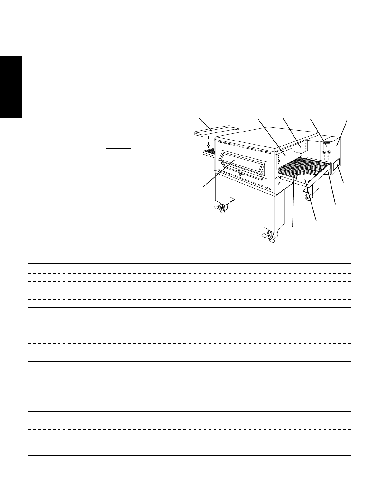
II. OVEN COMPONENTS - see Figure 1-1.
A. Window (on ovens so equipped): Allows the user to see
and access food products inside the baking chamber.
B. Conveyor Exit Tray: Prevents food products from falling off
the end of the moving conveyor.
C. Eyebrows (on ovens so equipped): Can be adjusted to
various heights to prevent heat loss into the environment.
D. End Plugs: Allow access to the oven's interior.
E. Control Panel: Location of the operating controls for the
oven. Refer to Section 3,
F. Machinery Compartment Access Panel: Allows access
to the oven's interior components. No user-servicable
parts are located inside the machinery compartment.
G. Serial Plate: Provides specifications for the oven that affect
installation and operation. Refer to Section 2, Installation,
for details.
H. Conveyor Drive Motor: Moves the conveyor.
I. Crumb Pans: Catch crumbs and other material that drop
through the conveyor belt. One crumb pan is located
underneath each end of the conveyor.
J. Conveyor: Moves the food product through the oven.
Operation, for details.
Not Shown:
K. Gas Burner (gas ovens) or Heating Elements (electric
ovens): Heat(s) air, which is then projected to the air
fingers by the blowers.
L. Blowers: Fans that project hot air from the gas burner or
heating elements to the air fingers.
M. Air Fingers: Project streams of hot air onto the food
product.
Fig. 1-1 - Oven Components
B
A
EDC
G
H
I
J
F
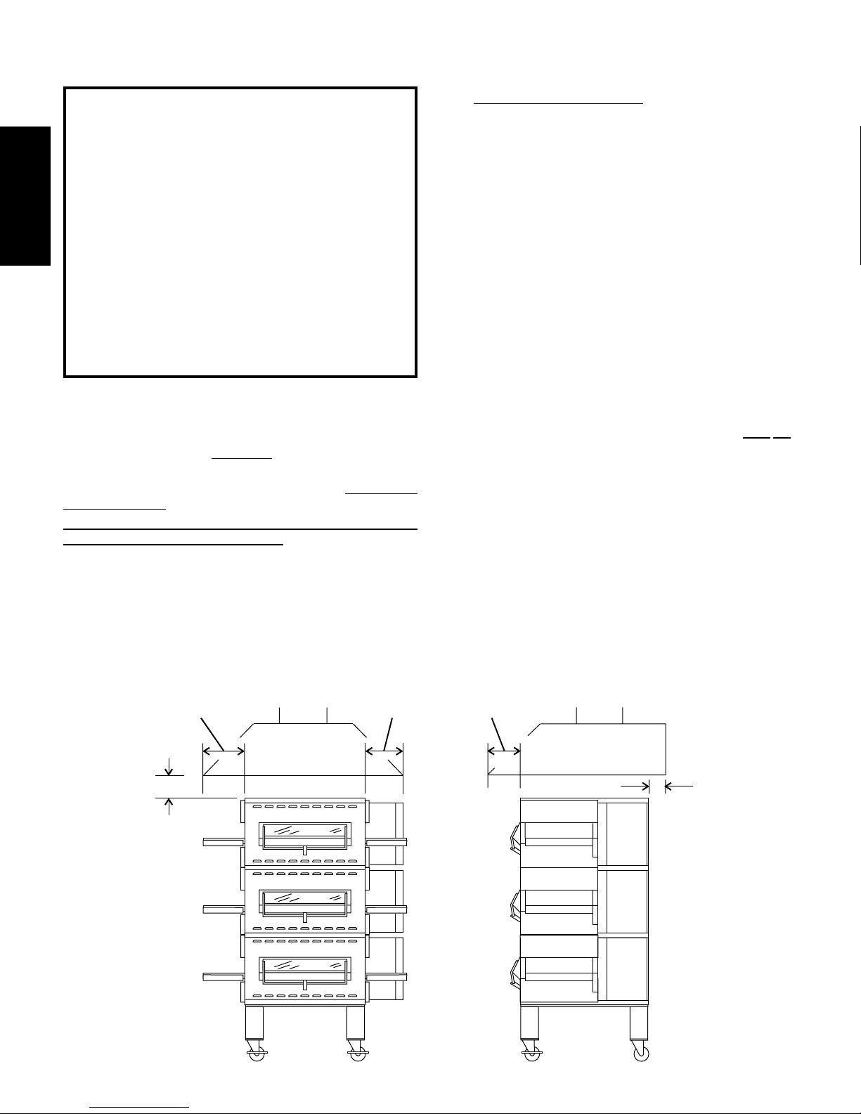
III. OVEN SPECIFICATIONS
Table 1-1: Dimensions
Overall Height: single oven with 17-1/2" (446mm) legs 43-1/2" (1105mm)
double oven with 17-1/2" (446mm) legs 63" (1600mm)
triple oven with 6" (152mm) legs 71" (1803mm)
Overall Depth: without front window 39-3/4" (1010mm)
with front window 43" (1092mm)
Overall Length: without exit tray installed 60" (1524mm)
with exit tray installed 68-1/4" (1734mm)
Baking Chamber Length 36" (914mm)
Conveyor Width: Single Belt 20" (508mm)
Split Belt 2 x 9-1/2" (241mm)
Conveyor Length 60" (1524mm)
Recommended Minimum Clearances:
Rear of oven to wall 3" (76mm)
Control end of conveyor to wall 18" (457mm)
Non-control end of oven to wall 3" (76mm)
Table 1-2: General specifications (per oven cavity)
Weight 400 lbs. (182kg)
Rated Heat Input: Natural gas ovens 50,000 BTU (12,600 kcal, 14.65 kW/hr.)
Propane ovens 45,000 BTU (11,340 kcal, 13.19 kW/hr.)
Electric ovens 16kW
Operating Temperature 200-600°F (93-316°C)
Warmup Time 25 minutes
4
Page 5
SECTION 1 - DESCRIPTION
Table 1-3: Electrical specifications for electric ovens (per oven cavity)
Main Blower Control Current Draw k W
Voltage Circuit Voltage Phase Freq. L1 L2 L3 N Rating Poles Wires
208V 120V conv. speed control, 3 Ph 60 Hz 50A 50A 50A -- 16.0 kW 4 Pole 4 Wire
drive motor, contactor, at 208V (3 hot, 1 gnd)
& temp. control; all others 208V
230V 120V conv. speed control, 3 Ph 60 Hz 45A 45A 45A -- 16.0 kW 4 Pole 4 Wire
drive motor, contactor, at 230V (3 hot, 1 gnd)
& temp. control; all others 230V
380V * 120V conv. speed control, 3 Ph 50 Hz 25A 25A 28A 5A 16.0 kW 4 Pole 5 Wire (3 hot,
drive motor, contactor, at 380V 1 neutral, 1 gnd)
& temp. control; 380V heating
elements; all others 240V
* 380V model is not approved by or .
Table 1-4: Electrical specifications for gas ovens (per oven cavity)
Main Blower Control Current
Voltage Circuit Voltage Phase Freq. Draw Poles Wires
208/240V 120V conv. speed control, 1 Ph 60 Hz 6A 3 Pole 4 Wire (2 hot, 1 neut, 1 gnd)
drive motor, contactor,
& temp. control; all others
as per line (208/240V)
ENGLISH
Table 1-5: Gas orifice and pressure specifications (per oven cavity)
Gas Type Main Orifice I.D. Pilot Orifice I.D. Supply (Inlet) Pressure Pressure
Natural 0.0935 (2.3749mm, #42 drill) 0.018 (0.46mm) 4-7 W.C. (9.95-17.4mbar) * 3.5 W.C. (8.7mbar)
Propane 0.0520 (1.3208mm, #55 drill) 0.018 (0.46mm) 11-14 W.C. (27.4-34.9mbar) * 10.5 W.C. (24.9mbar)
* The gas supply pressures shown are for ovens installed in North America. The required gas supply pressures of other locations are
dependent on the local gas type and on all applicable local codes.
Orifice (Manifold)
IMPORTANT
Additional electrical information is provided on the oven's serial plate, and on the wiring diagram inside the machinery
compartment.
5
Page 6
WARNING - For gas ovens, after any conversions, readjustments, or service work on the oven:
ENGLISH
For electric ovens, after any conversions, readjustments, or service work on the oven, check that the
The oven must be installed on an even (level) non-flammable flooring and any adjacent walls must
be non-flammable. Recommended minimum clearances are specified in the Description section of
Do not obstruct the flow of combustion and ventilation air to and from your oven. There must be no
obstructions around or underneath the oven. Constructional changes to the area where the oven is
SECTION 2 - INSTALLATION
Perform a gas leak test.
Test for correct air supply.
Test for proper combustion and gas supply.
Check that the ventilation system is in operation.
WARNING
ventilation system (if so equipped) is in operation.
WARNING
Keep the appliance area free and clear of combustibles.
WARNING
this Manual.
WARNING
installed shall not affect the air supply to the oven.
CAUTION
For additional installation information, contact your local Authorized Service Agent.
NOTE
There must be adequate clearance between the oven and combustible construction. Clearance
must also be provided for servicing and for proper operation.
NOTE
An electrical wiring diagram for the oven is located inside the machinery compartment.
NOTE
All aspects of the oven installation, including placement, utility connections, and ventilation requirements,
must conform with any applicable local, national, or international codes. These codes supercede the require-
ments and guidelines provided in this manual.
NOTE
In the USA, the oven installation must conform with local codes. In the absence of local codes, gas oven
installations must conform with the National Fuel Gas Code, ANSI Z223.1. Gas and electric ovens, when
installed, must be electrically grounded in accordance with local codes, or in the absence of local codes, with
the National Electrical Code (NEC), or ANSI/NFPA70.
NOTE
In Canada, the oven installation must conform with local codes. In the absence of local codes, gas oven
installations must conform with the Natural Gas Installation Code, CAN/CGA-B149.1, or the Propane Gas
Installation Code, CAN/CGA-B149.2, as applicable. Gas and electric ovens, when installed, must be electri-
cally grounded in accordance with local codes, or in the absence of local codes, with the Canadian Electrical
Code CSA C22.2.
In Australia, the oven installation must conform with any requirements of the appropriate statutory authority.
Gas oven installtions must conform with AGA Code, AG601.
NOTE
6
Page 7

Figure 2-1 - Installation Kit
SECTION 2 - INSTALLATION
3
7
1
2
8a 8b
ENGLISH
6
14
13
12
11
10
9
15
5
4
1
16
17
18
I. INSTALLATION KIT - see Figure 2-1
Item Single Oven Double Oven Triple Oven Part No. Description
1 1 2 3 42882 Top panel
2 2 2 2 220352 Screw, pan head #10 x 1" (top panel - front)
3 2 2 2 3A80A8801 Screw, pan head #10 x 2" (top panel - rear)
4 -- 1 2 44837 Stacking panel
5 -- 1 2 44918 Insulation, stacking panel, pre-cut
6 -- 4 8 4111A8815 Screw, hex head #10-32 x 1/2" (stacking panels)
7 1 1 1 42893 Base pad
8a 4 4 -- 42890 17-1/2" (445mm) leg extension, for single and double ovens
8b -- -- 4 44799 6" (152mm) leg extension, for triple ovens
9 2 2 2 22290-0009 Caster, with flat plate and brake
10 2 2 2 22290-0010 Caster, with flat plate (no brake)
11 1 1 1 21392-0004 Eyebolt, 3/4"
12 31 31 31 220373 Hex bolt, 3/8"-16 x 1"
13 32 32 32 21416-0001 Flat washer, 3/8"
14 32 32 32 21422-0001 Lockwasher, 3/8"
15 1 1 1 22450-0228 Restraint cable assembly
16 1 2 3 22361-0001 Gas hose
16 1 1 1 44727 Owner's Operating Manual, PS536 Gas and Electric Ovens
17 1 1 1 1002040 Middleby Marshall Authorized Service Agency Listing
Qty. Qty. Qty.
7
Page 8
SECTION 2 - INSTALLATION
II. VENTILATION SYSTEM
IMPORTANT
ENGLISH
Where national or local codes require the
installation of fire suppression equip-
ment or other supplementary equipment,
DO NOT mount the equipment directly to
the oven.
MOUNTING SUCH EQUIPMENT ON
THE OVEN MAY:
VOID AGENCY CERTIFICATIONS
RESTRICT SERVICE ACCESS
LEAD TO INCREASED SERVICE EX-
PENSES FOR THE OWNER
A. Requirements
CAUTION
Gas oven installations
ventilation system with electrical exhaust air sensing control.
A mechanically driven ventilation system is STRONGLY
RECOMMENDED for electric oven installations.
PROPER VENTILATION OF THE OVEN IS THE
RESPONSIBILITY OF THE OWNER.
REQUIRE a mechanically driven
B. Recommendations
NOTE THAT THE HOOD DIMENSIONS SHOWN IN FIGURE 22 ARE
RECOMMENDATIONS ONLY. LOCAL, NATIONAL AND
INTERNATIONAL CODES MUST BE FOLLOWED WHEN
INSTALLING THE VENTILATION SYSTEM. ANY APPLICABLE
CODES SUPERSEDE THE RECOMMENDATIONS SHOWN IN
THIS MANUAL.
The rate of air flow exhausted through the ventilation system
may vary depending on the oven configuration and hood design.
Consult the hood manufacturer or ventilation engineer for these
specifications.
To avoid a negative pressure condition in the kitchen area,
return air must be brought back to replenish the air that was
exhausted. A negative pressure in the kitchen can cause heatrelated problems to the oven components as if there were no
ventilation at all. The best method of supplying return air is
through the heating, ventilation and air conditioning (HVAC)
system. Through the HVAC system, the air can be temperaturecontrolled for summer and winter. Return air can also be
brought in directly from outside the building, but detrimental
effects can result from extreme seasonal hot and cold
temperatures from the outdoors.
NOTE: Return air from the mechanically driven system must not
blow at the opening of the baking chamber. Poor oven baking
performance will result.
C. Other ventilation concerns
Special locations, conditions, or problems may require the
services of a ventilation engineer or specialist.
Inadequate ventilation can inhibit oven performance.
It is recommended that the ventilation system and duct
work be checked at prevailing intervals as specified by the
hood manufacturer and/or HVAC engineer or specialist.
12" (305mm)
minimum
2" (51mm)
minimum
Fig. 2-2 - Ventilation System
12" (305mm)
minimum
8" (203mm)
minimum
8
1" (25mm)
minimum
Page 9
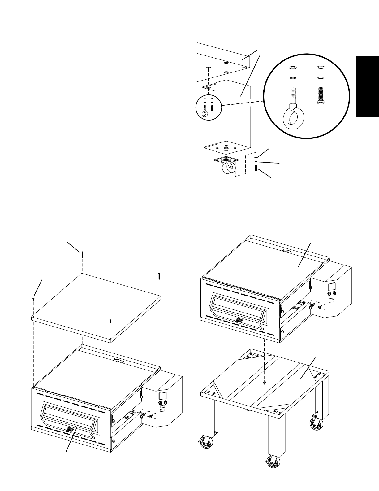
III. ASSEMBLY
A. Top Panel and Base Pad Assembly
1. Install the four leg extensions onto the base pad using the
3/8"-16x1" screws, 3/8" flat washers, and 3/8" lockwashers
supplied in the Base Pad Kit. See Figure 2-3. Check that
the finished sides of each leg extension face OUTWARDS.
One rear leg should be attached using three 3/8"-16 x 1"
screws and the 3/4" eyebolt, as shown in Figure 2-3. This
eyebolt acts as the anchor point for the restraint cable
assembly (see Part C,
2. Install one caster onto each leg extension, as shown in
Figure 2-4. Use the 3/8"-16x1" screws, 3/8" flat washers,
and 3/8" lockwashers supplied in the Installation Kit. The
locking casters should be installed at the FRONT of the
oven. The non-locking casters should be installed at the
REAR of the oven.
3. Install the top panel in place on the top oven cavity using the
screws included in the base pad kit, as shown in Figure 2-
4.
4. Install the lower oven cavity onto the base pad. Check that
the eyebolt welded onto the pad faces the rear of the oven.
Restraint Cable Installation).
SECTION 2 - INSTALLATION
Figure 2-3 - Leg extension and casters installation
Finished sides of
leg extension
face corner of
base pad
3/8" flat
washer
3/8" lock
washer
3/8"-16 x 1"
hex screw
3/4" eyebolt
(inside corner of
one rear leg
extension
only)
3/8" flat
washer
3/8" lock
washer
Locking casters -
FRONT of oven
Non-locking casters -
REAR of oven
3/8"-16 x 1"
hex screw
ENGLISH
#10 x 2" screws
attach rear of
top panel
#10 x 1" screws
attach front of
top panel
Figure 2-4 - Top panel and base pad installation
Bottom oven
cavity
Assembled
base pad
Top oven
cavity
9
Page 10
SECTION 2 - INSTALLATION
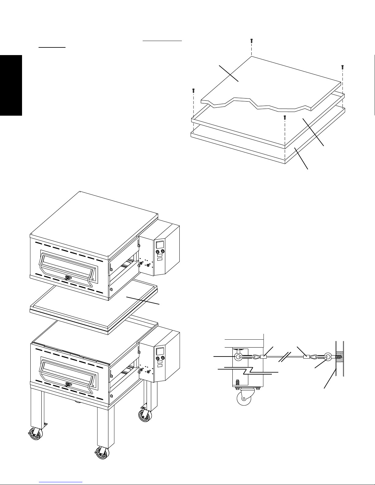
B. Stacking
Figure 2-5 - Assembling the stacking spacers
For single ovens, skip ahead to Part C, Restraint Cable
Installation. For double or triple ovens, continue on to Step
1, below.
1. Assemble the stacking spacer(s) as shown in Figure 2-5.
ENGLISH
One spacer assembly is supplied for a double oven, while
two are supplied for a triple oven.
2. Place one of the assembled spacers on top of the lower
oven cavity, making sure that the insulation faces up.
3. Place the center oven cavity (for triple ovens) or the top oven
cavity (for double ovens) on top of the spacer. Check that
all four sides of the spacer overlap the base of the oven, and
that the oven is level and firmly seated. See Figure 2-6.
4. For triple ovens, repeat Steps 2 and 3 to install the top oven
cavity.
Figure 2-6 - Stacking
#10-32 x 1/2"
hex screws
1-1/2" (38mm)-thick
insulation, pre-cut
Stacking panel,
P/N 44837
Top panel,
P/N 42882
Assembled
spacer
(insulation
faces up)
C. Restraint Cable Installation
Because the oven is equipped with casters, a restraint cable
assembly must be installed to limit the movement of the
appliance without depending on the connector and the quick
disconnect device or its associated piping. One end of the cable
is anchored to the eyebolt on one of the rear leg extensions,
while the other is anchored to the wall. See Figure 2-7.
After connecting the restraint cable, move the oven to its final
location. Then, lock the two front casters.
Figure 2-7 - Installing the Restraint Cable
Restraint cable
3/8"-16 x 1"
eyebolt on
rear leg
extension
assembly
3/4 (19mm)
eyebolt
Wall of
structure
10
Page 11
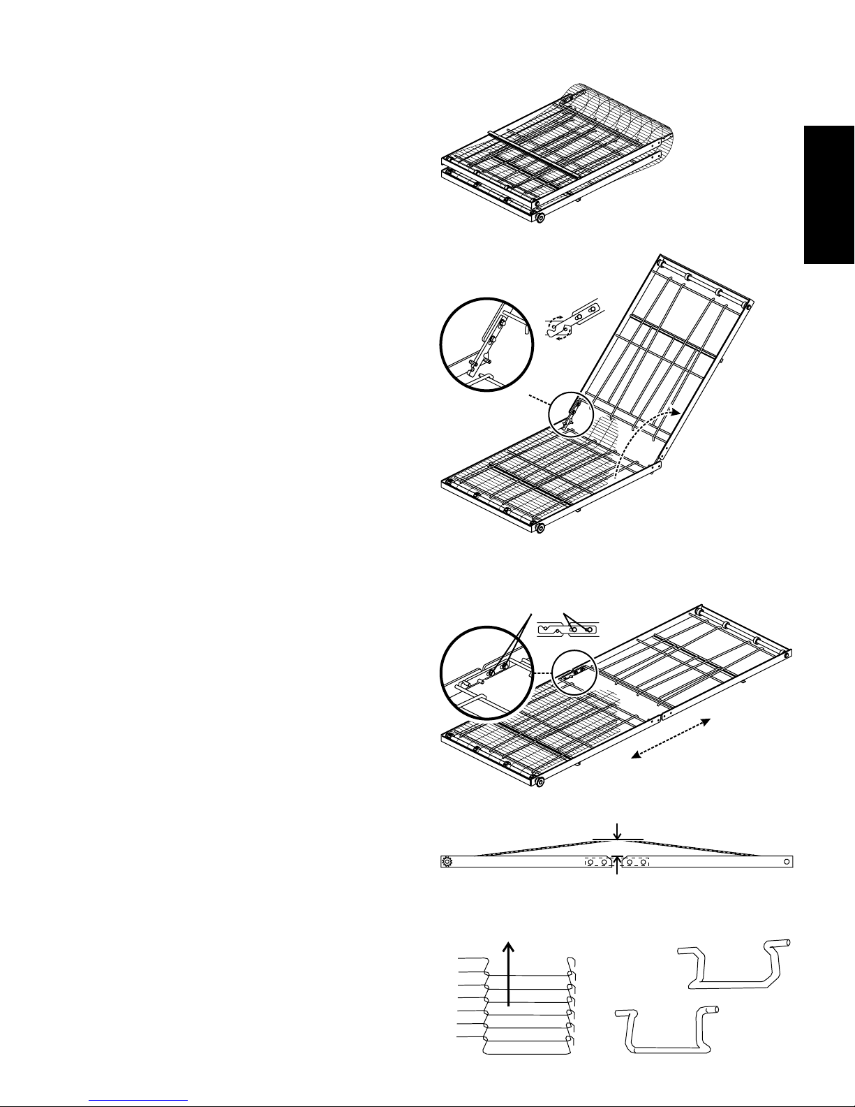
D. Conveyor Installation
1. Unfold the conveyor frame so that it lies flat on the floor. As
you unfold the frame, check that the locator pins shown in
Figure 2-8 lock into the slots on the bracket.
2. Refer to Figure 2-8. Note the locations of the four tensioning
screws (2 per side) in the slotted holes on the brackets.
Loosen these screws to allow the conveyor to be properly
tensioned.
3. Lift the conveyor belt away from the frame, as shown in
Figure 2-8, to check the belt tension. The belt should lift
between 1-2" (25-50mm).
SECTION 2 - INSTALLATION
Figure 2-8 - Assembling and tensioning the conveyor
Folded
frame
ENGLISH
If it is necessary to adjust the belt tension, gently push the
two conveyor frame sections closer together, or further
apart, as required. Then, re-check the tension of the
conveyor belt. Repeat this step as necessary until the
proper belt tension is achieved.
4. When the belt tension is correctly adjusted, tighten the two
tensioning screws on each side of the conveyor frame.
This fastens the two frame sections together at the correct
belt tension.
5. If it is necessary to add or remove conveyor links to achieve
the correct tension, OR if it is necessary to reverse the
conveyor belt for correct orientation, the belt will need to be
removed from the conveyor frame. If this is necessary,
perform the following procedure:
a. Remove the master links using long-nose pliers.
Then, roll up the belt along the length of the conveyor
frame.
b. Add or remove belt links as necessary to achieve the
correct belt tension.
c. Replace the belt on the conveyor frame. Check the
following:
The conveyor belt links must be oriented as shown
in Figure 2-9.
The smooth side of the conveyor belt must face
UP.
d. Connect the inside master links. Check that the links
are oriented as shown in Figure 2-9.
e. Connect the outside master links. Note that the
outside master links each have an open hook on one
side. This hook aligns with the hooks along the sides
of the other conveyor links. See Figure 2-9.
Pins on frame
fit into slots
on bracket
Tensioning
screws in slotted
holes (2 per side)
With tensioning
screws loosened,
frame sections can
be moved to adjust
belt tension
1-2" (25-50mm)
vertical deflection
11
Figure 2-9 - Conveyor and Master Link Orientation
Direction
of travel
Incorrect
master link
position
CORRECT
master link
position
Page 12
SECTION 2 - INSTALLATION
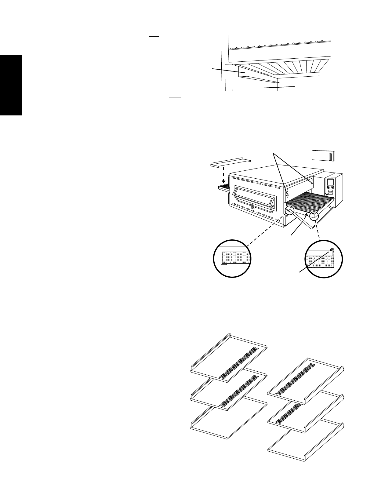
6. Lift the conveyor and position it in the oven. The conveyor
can only be installed from the end of the oven with the drive
motor.
7. Continue moving the conveyor into the oven until the conveyor frame is positioned properly. The inside supports for
ENGLISH
the crumb trays should rest firmly against the lower end
plugs, as shown in Figure 2-10.
8. When the conveyor is positioned properly, check for freedom of movement of the conveyor belt by pulling it for about
2-3 feet (60 to 90 cm) with your fingers. The conveyor
move freely.
9. Install the drive chain between the conveyor drive sprocket
and the motor sprocket. To install the chain, it will be
necessary to lift the drive end of the conveyor slightly.
V. FINAL ASSEMBLY
must
Crumb tray
support
bracket
Figure 2-10 - Conveyor placement
End plug
Figure 2-11 - Final assembly
Wing screws
2 per end plug
Chain cover:
Place down over
conveyor sprocket
1. Install the conveyor drive motor cover as shown in Figure
2-11.
2. Install the crumb trays as shown in Figure 2-11. First, place
the inside edge of each tray onto its support bracket. Then,
hook the outside edge of the tray over the end of the
conveyor frame.
Note that crumb trays for the lower (or a single) oven are
solid, while those for all upper ovens have perforated
openings, as shown in Figure 2-12.
3. Press the conveyor exit tray down over the edge of the
conveyor frame at the exit end of the oven. See Figure 2-11.
Conveyor
exit tray:
Press down
over end of
conveyor
Crumb trays (2):
1. Place inside
edge on support
bracket
2. Hook outside
edge over
conveyor frame
Figure 2-12 - Crumb trays
Crumb trays
WITH openings -
all upper ovens
Crumb trays
WITHOUT openings -
lower oven only
12
Page 13
VI. ELECTRICAL SUPPLY
WARNING
Authorized supplier personnel normally accomplish
the connections for the ventilation system, electric supply,
and gas supply, as arranged by the customer. Following
these connections, the factory-authorized installer can
perform the initial startup of the oven.
NOTE: The electric supply installation must satisfy the
requirements of the appropriate statutory authority, such as the
National Electrical Code (NEC), ANSI/NFPA70, (U.S.A.); the
Canadian Electrical Code, CSA C22.2; the Australian Code,
AG601; or other applicable regulations.
NOTE: The electric supply connection must meet all national
and local electrical code requirements.
Check the oven serial plate before making any electric supply
connections. Electric supply connections must agree with data
on the oven serial plate. The location of the serial plate is shown
in Figure 1-1 (in Section 1, Description).
A fused disconnect switch or a main circuit breaker
(customer furnished) MUST be installed in the electric
supply line for each oven cavity. It is recommended
that this switch/circuit breaker have lockout/tagout
capability.
The supply conductors must be of the size and
material (copper) recommended. Refer to the wiring
diagram inside the machinery compartment of the
oven. Electrical specifications are also listed on the
oven's serial plate and in Tables 1-3 and 1-4, Electrical Specifications (in Section 1, Description).
The oven requires a ground connection to the oven
ground screw located in the electrical junction box.
(The box is shown in Figure 2-13.) If necessary, have
the electrician supply the ground wire. Do NOT use
the wiring conduit or other piping for ground
connections!
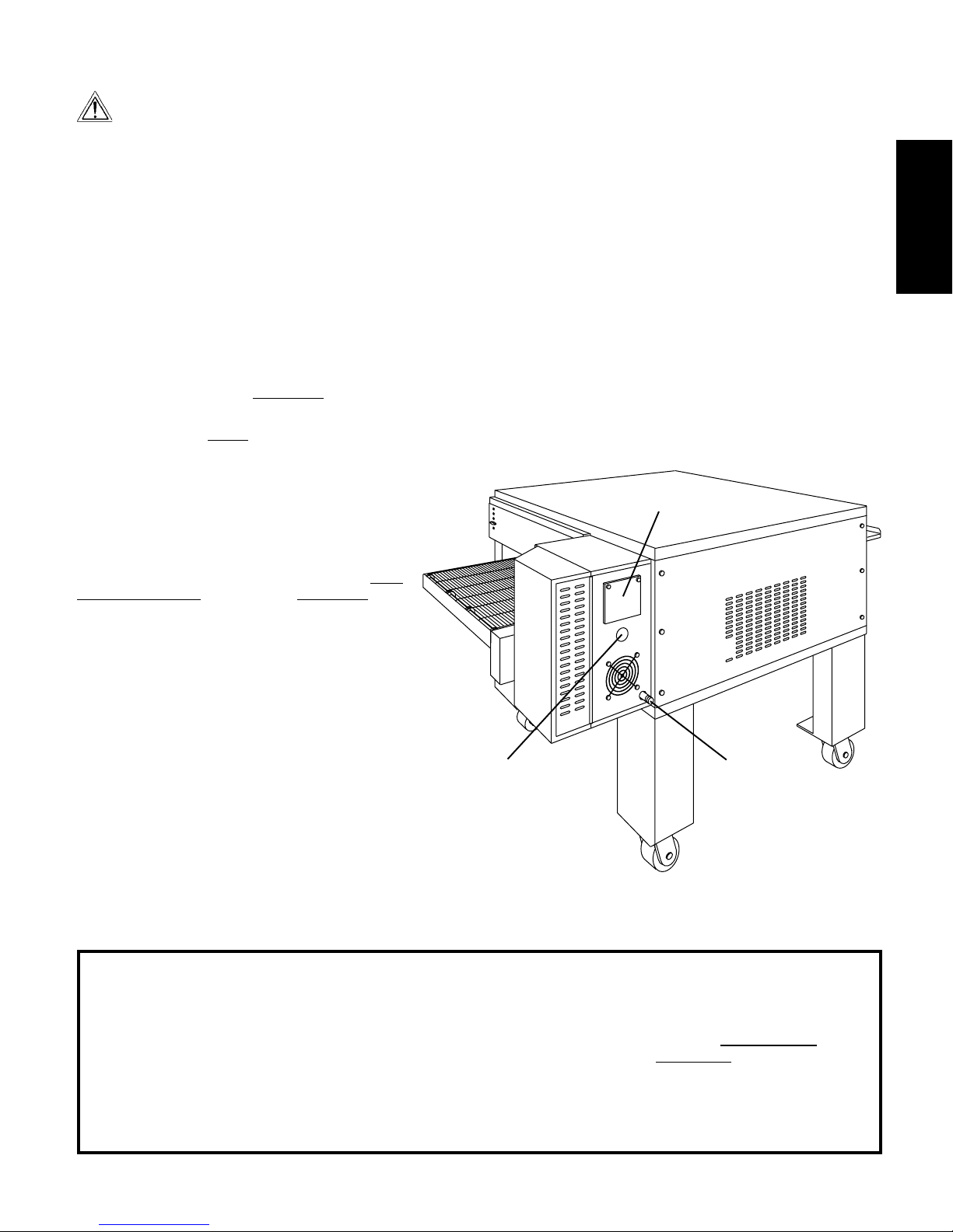
A. Additional Information - Gas Ovens
All electric supply connections are made at the
terminal block located in the electrical junction
box, shown in Figure 2-13. The power lines then
connect to the oven circuits through a safety
switch located inside the machinery compartment. This switch interrupts electric power to the
oven when the Machinery Compartment Access
Panel is opened.
1.3" (33mm) cutout for
electric utility connection
(electric ovens only)
SECTION 2 - INSTALLATION
B. Additional Information - Electric Ovens
A 1.3" (33mm) dia. cutout in the back wall of the machinery
compartment provides access to the electrical supply
connections. The actual wiring connections are made at
the terminal block located in the electrical junction box.
Using flexible cables for the electric power supply
conductors requires a 1.3" (33mm) strain-relief fitting (not
furnished with the oven) to enable safe access to the
terminal block.
C. Connection
Refer to the wiring diagram inside the machinery
compartment of the oven to determine the correct
connections for the electrical supply lines. Connect the
supply as indicated on the wiring diagram.
Figure 2-13 - Utility connection locations
Electrical
Junction Box
1/2" NPT pipe for gas
utility connection
(gas ovens only)
ENGLISH
VII. GAS SUPPLY
CAUTION
DURING PRESSURE TESTING NOTE ONE OF THE FOLLOWING:
1. The oven and its individual shutoff valve must be disconnected from the gas supply piping system during any
pressure testing of that system at test pressure in excess
of 1/2 psi (3.45 kPa).
2. The oven must be isolated from the gas supply piping
system by closing its individual manual shutoff valve during any pressure testing of the gas supply piping system at
test pressure equal to or less than 1/2 psi (3.45 kPa).
3. If incoming pressure is over 14 W.C. (35mbar), a separate regulator MUST be installed in the line BEFORE the
individual shutoff valve for the oven.
WARNING: To prevent damage to the control valve regulator during initial turn- on of gas, it is very important to open
the manual shutoff valve very slowly.
After the initial gas turn-on, the manual shutoff valve must
remain open except during pressure testing as outlined in
the above steps or when necessary during service maintenance.
13
Page 14
SECTION 2 - INSTALLATION
A. Gas Utility Rough-In Recommendations
The following gas system specifications are STRONGLY
RECOMMENDED. Deviating from these recommendations
may affect the baking performance of the oven.
Gas Meter - 650 cfh meter
ENGLISH
Gas Line
DEDICATED LINE from the gas meter to the oven
2" (50.8mm) pipe for natural gas
1-1/2" (38.1mm) pipe for propane
Maximum length: 200' (61m). Each 90° elbow equals 7'
(2.13m) of pipe.
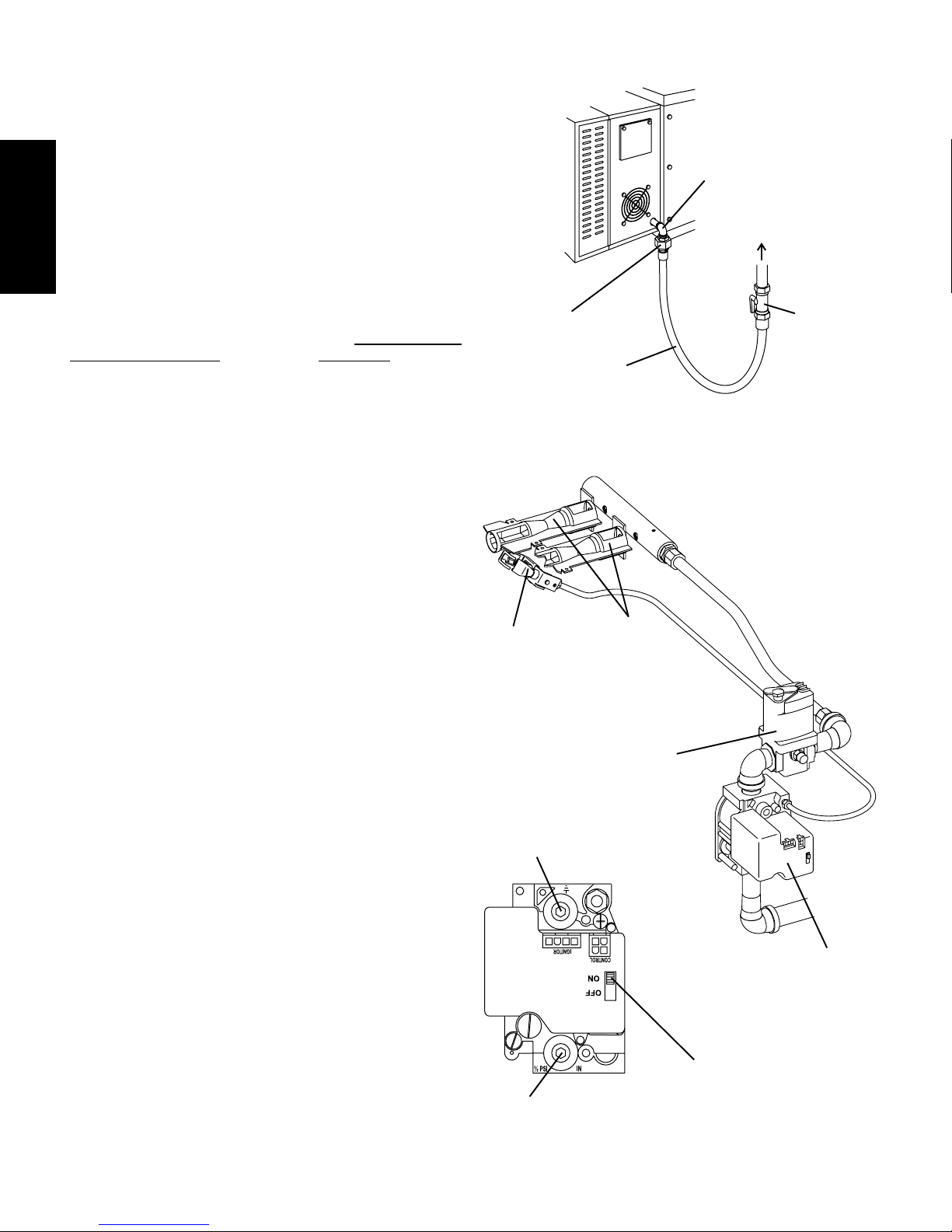
B. Connection
Check the ovens gas supply requirements before making the
gas utility connection. Gas supply requirements are listed on
the ovens serial plate and in Table 1-5, Gas Orifice and
Pressure Specifications (in Section 1, Description).
Check the serial plate to determine the type of gas (Propane or
Natural) to be used with the oven.
Refer to the instructions in the gas hose package (included in
the Installation Kit) before connecting the gas line. One gas line
connection method is shown in Figure 2-14; however,
compliance with the applicable standards and regulations is
mandatory.
Inlet and regulated gas pressure readings can be taken using
a U tube manometer at the tap locations shown in Figure 2-
15.
NOTE
In the USA, the installation must conform with local codes, or in
the absence of local codes, with the National Fuel Gas Code,
ANSI Z223.1.
In Canada, the installation must conform with local codes, or in
the absence of local codes, with the Natural Gas Installation
Code, CAN/CGA-B 149.1, or the Propane Installation Code,
CAN/CGA-B 149.2, as applicable.
In Australia, the installation must conform with AGA Code
AG601 and with any requirements of the appropriate statutory
authority.
Certain safety code requirements exist for the installation of gas
ovens; refer to the beginning of Section 2 for a list of the
installation standards. In addition, because the oven is equipped
with casters, the gas line connection shall be made with:
A connector that complies with the Standard for Connec-
tors for Movable Gas Appliances, ANSI Z21.69 (in USA), or
Connectors for Movable Gas Appliances, CAN/CGA-6.16
(in Canada), AND
A quick-disconnect device that complies with the Standard
for Quick-Disconnect Devices for Use With Gas Fuel, ANSI
Z21.41 (in USA.), or, if applicable, Quick-Disconnect Devices for Use With Gas Fuel, CAN1-6.9 (in Canada).
C. Gas Conversion
Where permitted by local and national codes, it is possible to
convert ovens from natural to propane gas, or from propane to
natural gas. Use the appropriate Middleby Marshall Gas
Conversion Kit for the specific oven model.
CAUTION
The terms of the oven's warranty require all start-ups, conversions and service work to be performed by a Middleby Marshall
Authorized Service Agent.
Pilot
assembly
Manifold
pressure tap
(where manifold
gas pressure is
measured)
Inlet pressure
tap (where
incoming gas
pressure is
measured)
14
Figure 2-14 - Flexible Gas Hose Installation
90°
Elbow
To Gas
Supply Pipe
Union OR
quick-
disconnect
device
Flexible
Gas Hose
Figure 2-15 - Gas Burner and Piping Assembly
In-shot
burners (2)
Modulating
gas valve
Combination Gas
Control Valve
(Safety Regulator)
On/Off Switch
Always leave in ON position
Full-Flow
Gas
Shutoff
Valve
Page 15
SECTION 3 - OPERATION
I. LOCATION AND DESCRIPTION OF CONTROLS
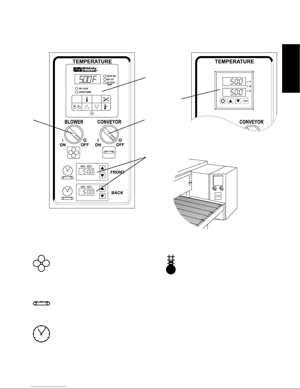
Fig. 3-1 - Control Panel
D
ENGLISH
D
A
B
C
A.
B.
"BLOWER" Switch: Turns the blowers and
cooling fans on and off. When set to the "ON" (I)
position, it also allows the burner (gas ovens)
or heating elements (electric ovens) to activate.
Activation is determined by the settings on the
Digital Temperature Controller.
"CONVEYOR" Switch: Turns the conveyor drive
motor on and off.
D.
Digital Temperature Controller: Continuously
monitors the oven temperature. Settings on the
Digital Temperture Controller control the activation of the burner or heating elements. Keypad
controls allow the operator to select the cooking
temperature and monitor oven operation.
Note that two different models of Digital Temperature Controller are used on PS536 ovens.
This section provides instructions specific to
each controller.
C.
Conveyor Speed Controller: Adjusts and displays the bake time. Single-belt ovens have one
controller. Split belt ovens have one controller
for each conveyor belt, labeled "FRONT" and
"BACK."
NOT SHOWN:
E. Machinery Compartment Access Panel Safety Switch:
Disconnects electrical power to the controls and the blowers when the machinery compartment access panel is
opened. The panel should only be opened by authorized
service personnel.
15
Page 16
SECTION 3 - OPERATION
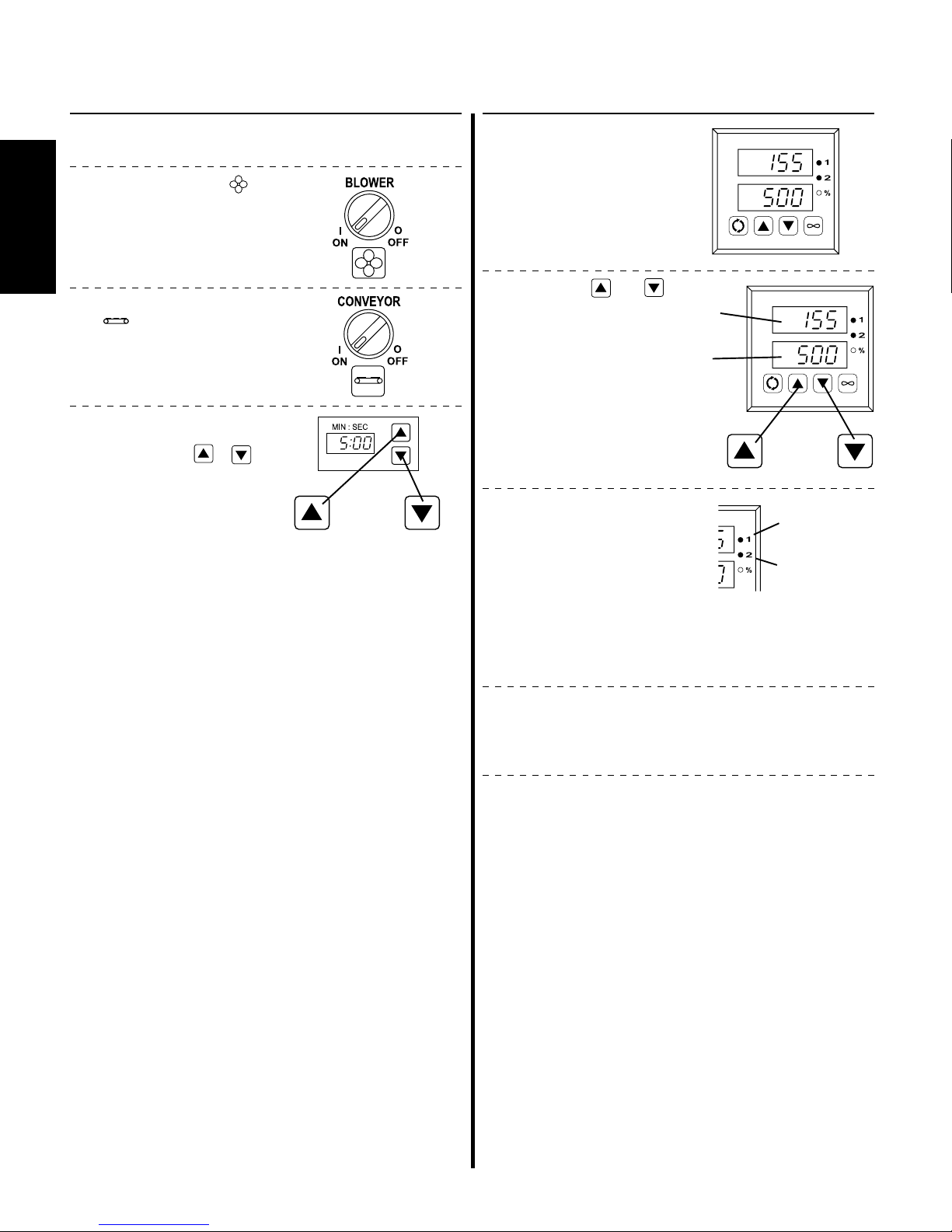
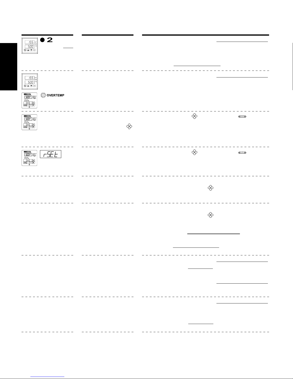
II. NORMAL OPERATION - STEP-BY-STEP
A. DAILY STARTUP PROCEDURE
1. Check that the circuit breaker/fused disconnect is in the on
ENGLISH
position. Check that the window (if so equipped) is closed.
2. Turn the "BLOWER" ( )
switch to the ON ("I")
position.
3. Turn the "CONVEYOR"
) switch to the ON
(
("I") position.
4. If necessary, adjust the
conveyor speed setting
by pressing the
pushbuttons on the conveyor speed controller to
change the displayed
bake time.
or
or
If the oven uses this
Digital Temperature
Controller:
5a. Press the
pushbuttons on the digital temperature controller to adjust the set temperature, if necessary.
Note that the set temperature is shown in the lower
window of the display,
while the actual oven
temperature is shown in
the upper window.
6a. Check that the "1" light
illuminates. This shows
that the burner or heating
elements have been
turned on.
The "2" light will illuminate while the oven heats
to its minimum normal
operating temperature of
200°F/93°C.
or
Actual
temp
Set
temp
or
Heating
elements on
Oven
temperature
under 200°F/
93°C
7a. Wait for the oven to heat to the set point temperature. Higher
set point temperatures will require a longer wait. The oven
can reach a temperature of 500°F (232°C) in approximately
15 minutes.
8a. Allow the oven to preheat for 10 minutes after it has reached
the set point temperature.
16
Page 17
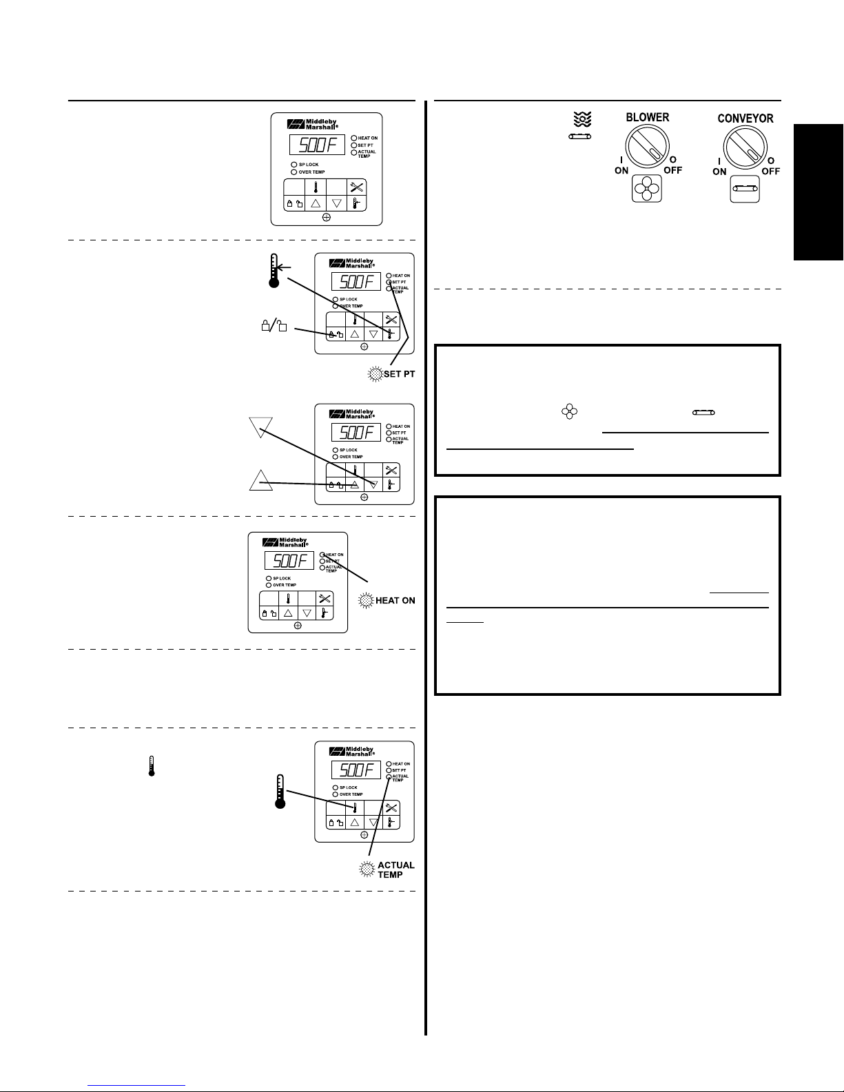
B. DAILY SHUTDOWN PROCEDURE
SECTION 3 - OPERATION
If the oven uses this
Digital Temperature
Controller:
5b. Adjust the temperature
controller to a desired set
temperature, if necessary.
Press the Set Point
and Unlock keys at
the same time. Wait
for the "SET PT" light
to turn on.
Press the Up Arrow
and Down Arrow
Keys as necessary
to adjust the setpoint.
6b. Check that the "HEAT ON"
light illuminates. This
shows that the burner or
heating elements have
been turned on.
7b. Wait for the oven to heat to the setpoint temperature. Higher
setpoint temperatures will require a longer wait. The oven
can reach a temperature of 500°F (232°C) in approximately
5 minutes.
+
wait
for
or
wait
for
1. Turn the "BLOWER" ( )
and "CONVEYOR" (
switches to the "OFF"
("O") position. Open the
window (if so equipped)
to allow the oven to cool
faster.
Note that the blowers will
remain in operation until
the oven has cooled to
below 200°F (93°C).
3. After the oven has cooled and the blowers are off, switch the
circuit breaker/fused disconnect to the off position.
)
+
IMPORTANT
On gas ovens, if the "HEAT ON" light will not illuminate, OR
if the oven does not heat, the gas burner may not have lit.
Turn the "BLOWER"
to the "OFF" ("O") position.
UTES before restarting the oven. Then, repeat the Daily
Startup procedure.
( ) and "CONVEYOR" ( ) switches
Wait for AT LEAST FIVE MIN-
CAUTION
In case of power failure, turn all switches to the OFF ("O")
position, open the oven window (if so equipped), and
remove the product. After the power has been restored,
perform the normal startup procedure. IF THE OVEN WAS
SWITCHED OFF FOR LESS THAN 5 MINUTES,
AT LEAST FIVE MINUTES BEFORE RESTARTING THE
OVEN.
No attempt should be made to operate the oven during a
power failure. In gas ovens, the burner will not operate
and gas will not flow through the burner without electric
power.
WAIT FOR
ENGLISH
8b. (Optional) Press the Tem-
perature (
the Actual Temperature
in the display, and wait
for the "ACTUAL TEMP"
light to turn on. This allows you to monitor the
oven temperature as it
rises to the setpoint.
9b. Allow the oven to preheat for 10 minutes after it has reached
the set point temperature.
) key to show
wait
for
17
Page 18
SECTION 3 - OPERATION
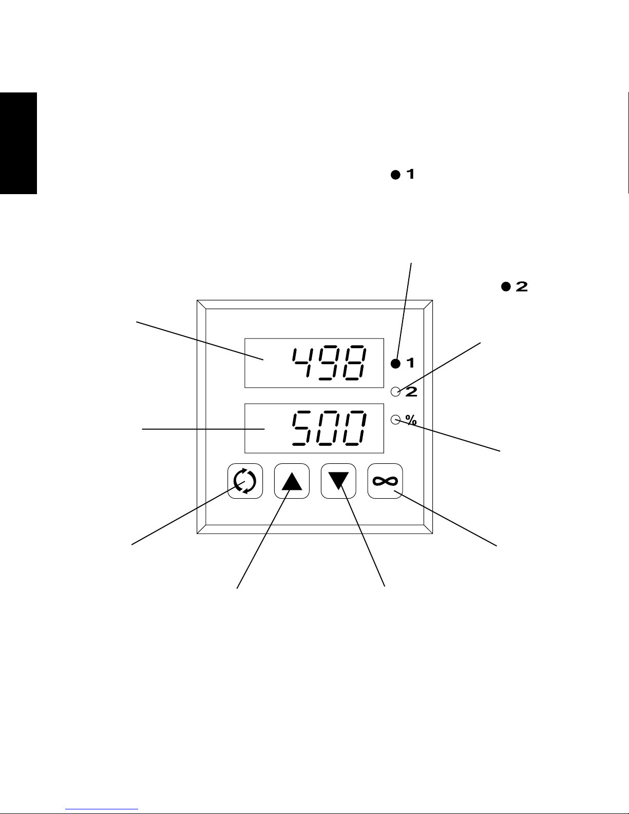
III. QUICK REFERENCE: DIGITAL TEMPERATURE CONTROLLERS
ENGLISH
Upper display
Shows the actual
oven temperature.
light
Illuminates when the burner
or heating elements are on.
This light will flicker during
normal operation after the
oven reaches the set point
temperature.
light
Illuminates when
oven temperature is
EITHER below
200°F/93°C
OR above 600°F/
316°C.
Lower display
Shows the set
point temperature.
Advance key
Service use only.
Up Arrow key
Increases the set
point temperature.
Press the key once
to change the set
point by one degree.
Hold the key down
for larger changes.
Percent
indicator
light
Service use only.
Infinity key
Service use only.
Down Arrow key
Decreases the set point
temperature. Press the
key once to change the
set point by one degree.
Hold the key down for
larger changes.
18
Page 19
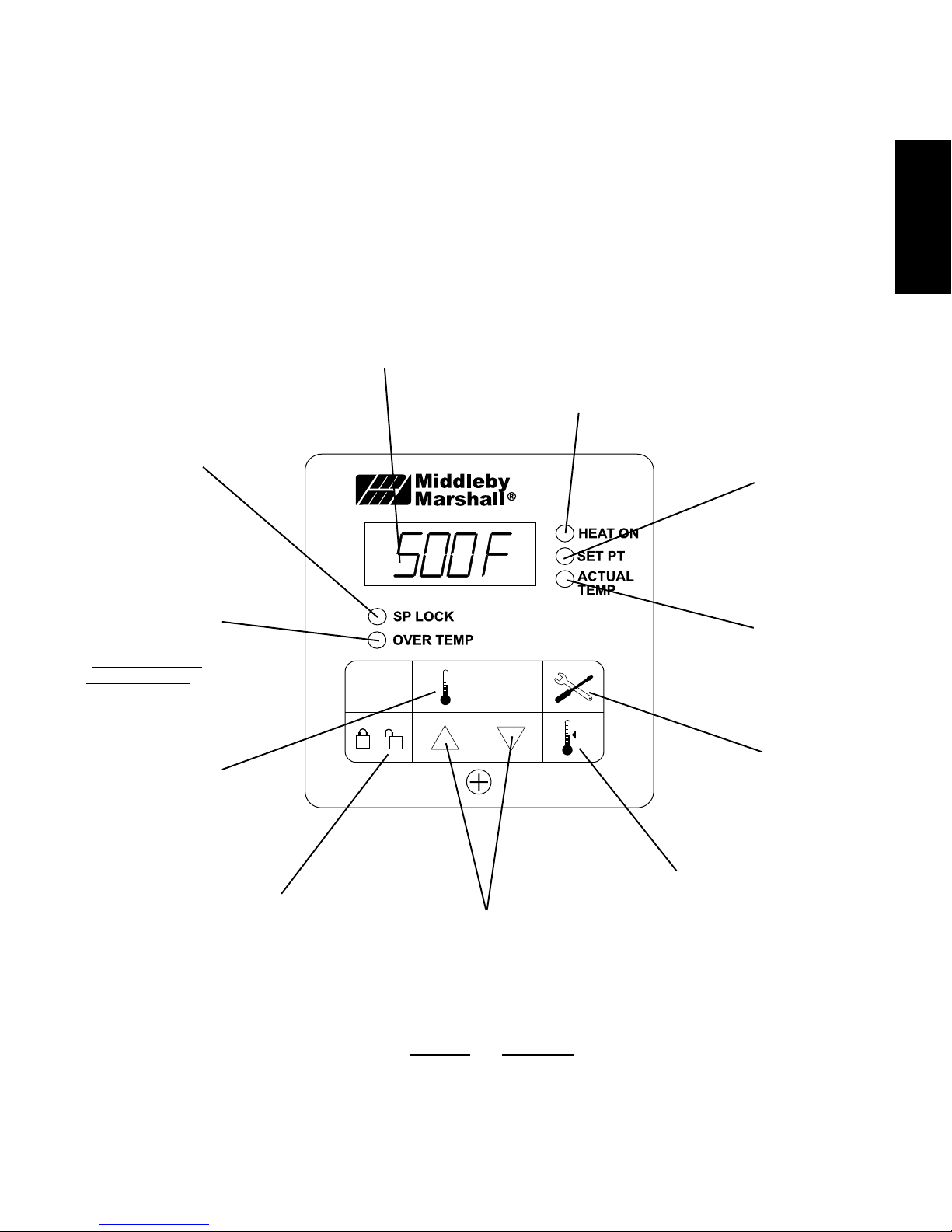
SECTION 3 - OPERATION
"SP LOCK"
Light
Lights when the
set point is locked
out from changes.
This setting can
only be changed by
service personnel.
OVERTEMP
Light
Lights when the oven
temperature is
greater than 650°F
(343°C). Refer to
Quick Reference:
Troubleshooting in
this section.
Display
Shows the Set Point
or the Actual Tem-
perature in degrees
Fahrenheit (F) or
Celsius (C).
"HEAT ON"
Light
Lights when the
burner or heating
elements, as
appropriate for the
oven model, are in
operation.
ENGLISH
"SET PT"
(setpoint)
Light
Lights when the
set point is shown
in the display.
"ACTUAL
TEMP" Light
Lights when the
Actual Tempera-
ture is shown in
the display.
Temperature
Key
Press this key once
to view the Actual
Temperature in the
Display.
together with the Set
Point Key to allow the
changed. Changes
can only be made for
Unlock Key
Press this key
Set Point to be
60 seconds.
Up Arrow and Down
Arrow Keys
Press these keys to
adjust the Set Point up or
down. If the Set Point will
not change, refer to Set
Point Key and Unlock Key
in this section.
19
Service Key
Service use
only.
Set Point Key
Press this key
together with the
Unlock Key to allow
the Set Point to be
changed.
Changes can only be
made for 60 sec-
onds.
Page 20
SECTION 3 - OPERATION
IV. QUICK REFERENCE: TROUBLESHOOTING
SYMPTOM PROBLEM SOLUTION
ENGLISH
light illu-
minates
after
oven has been
operating normally
Oven shuts down
completely during operation
light is lit, oven will
not heat
Oven shuts down
shortly after it is
turned on
(gas ovens only)
appears in display, oven is not
heating
The oven temperature is in
excess of 600°F (316°C). If
the oven is left in operation,
the temperature may rise to
650°F (343°C) and cause a
shutdown.
The oven temperature exceeded 650°F (343°C), and
the oven was automatically
shut down.
The gas burner did not light
within 90 seconds of turning the "BLOWER"
( )
Switch to the ON ("I") position. This engages a safety
lockout mode.
The oven did not reach
200°F (93°C) within 15 minutes of startup, and has
stopped heating.
Turn the oven off according to the Daily Shutdown Procedure.
Allow the oven to cool. Regardless of the time that is required
for the oven to cool, wait for AT LEAST FIVE MINUTES before
restarting the oven.
Repeat the
Daily Startup Procedure.
Turn the oven off according to the Daily Shutdown Procedure.
Contact your Middleby Marshall Authorized Service Agent to
determine and correct the cause of the condition to prevent
damage to the oven.
Turn the "BLOWER" ( ) and "CONVEYOR" ( )switches to
the "OFF" ("O") position.
Wait for AT LEAST FIVE MINUTES before restarting the oven.
Repeat the Daily Startup procedure.
Turn the "BLOWER"
( ) and "CONVEYOR" ( )switches to
the "OFF" ("O") position.
Wait for AT LEAST FIVE MINUTES before restarting the oven.
Repeat the Daily Startup procedure.
Oven will not
turn on at all
Oven will not heat
Oven is operating, but
little or no air is blowing
from air fingers
Conveyor moves with a
jerky motion, or will not
move at all
Electrical power may not be
reaching the oven, or the
controls may be set incorrectly.
Controls may be set incorrectly.
Check that the circuit breaker/fused disconnect is turned on.
Check that the "BLOWER"
( ) Switch is in the ON ("I")
position. The burner cannot engage until the blowers are in
operation.
Check that the Set Point is correctly set.
Check that the "BLOWER"
( ) Switch is in the ON ("I")
position.
If the oven still will not heat, turn the oven off according to the
instructions in the Daily Shutdown Procedure.
Wait for AT LEAST FIVE MINUTES before restarting the oven.
Repeat the Daily Startup Procedure. Check that the Set Point
is above 200°F (93°C).
Air fingers may have been
reassembled incorrectly
after cleaning.
Turn the oven off according to the
Refer to Section 4, Maintenance, for instructions on reassem-
bling the air fingers.
Daily Shutdown Procedure.
Blower belt may be broken. Turn the oven off according to the Daily Shutdown Procedure.
Contact your Middleby Marshall Authorized Service Agent to
correct the problem.
Conveyor may be jammed
on an object in the oven, or
conveyor belt or drive chain
may be overtightened.
Turn the oven off according to the
Check if the conveyor is blocked by an object inside the oven.
Check that the conveyor drive chain is not overtightened.
Daily Shutdown Procedure.
Refer to Section 4, Maintenance, for instructions on checking
the conveyor belt tension.
Food products are
overcooked or
Controls may be set incorrectly.
undercooked
IF THESE STEPS FAIL TO RESOLVE THE PROBLEM, CONTACT YOUR LOCAL MIDDLEBY MARSHALL AUTHORIZED
SERVICE AGENT. A SERVICE AGENCY DIRECTORY IS SUPPLIED WITH YOUR OVEN.
Check that the set temperature and bake time settings are
correct.
20
Page 21
SECTION 4 - MAINTENANCE
WARNING
Before ANY cleaning or servicing of the oven, perform the following procedure:
1. Switch off the oven and allow it to cool. Do NOT service the oven while it is warm.
2. Turn off the electric supply circuit breaker(s) and disconnect the electric supply to the oven.
3. If it is necessary to move a gas oven for cleaning or servicing, disconnect the gas supply before moving the oven.
When all cleaning and servicing is complete:
1. If the oven was moved for servicing, return the oven to its
original location.
2. For gas ovens, reconnect the gas supply.
3. Reconnect the electrical supply.
4. If the restraint cable was disconnected to clean or service
the oven, reconnect it at this time.
5. For gas ovens, turn on the full-flow gas safety valve. Test
the gas line connections for leaks using approved leak
test substances or thick soap suds.
6. Turn on the electric supply circuit breaker(s).
7. Perform the normal startup procedure.
WARNING
Possibility of injury from moving parts and electrical shock exists in this oven. Switch off and lockout/tagout the electric supply
BEFORE beginning to disassemble, clean, or service any oven. Never disassemble or clean an oven with the BLOWER switch
or any other circuit of the oven switched on.
CAUTION
NEVER use a water hose or pressurized steam-cleaning equipment when cleaning this oven. DO NOT use excessive
amounts of water, to avoid saturating the oven insulation. DO NOT use a caustic oven cleaner, which can damage the bake
chamber surfaces.
NOTE
ANY replacement parts that require access to the interior of the oven may ONLY be replaced by a Middleby Marshall Authorized
Service Agent. It is also strongly recommended that the 3-Month Maintenance and 6-Month Maintenance procedures in this
section be performed ONLY by a Middleby Marshall Authorized Service Agent.
ENGLISH
I. MAINTENANCE - DAILY
A. Check that the oven is cool and the power is disconnected,
as described in the warning at the beginning of this Section.
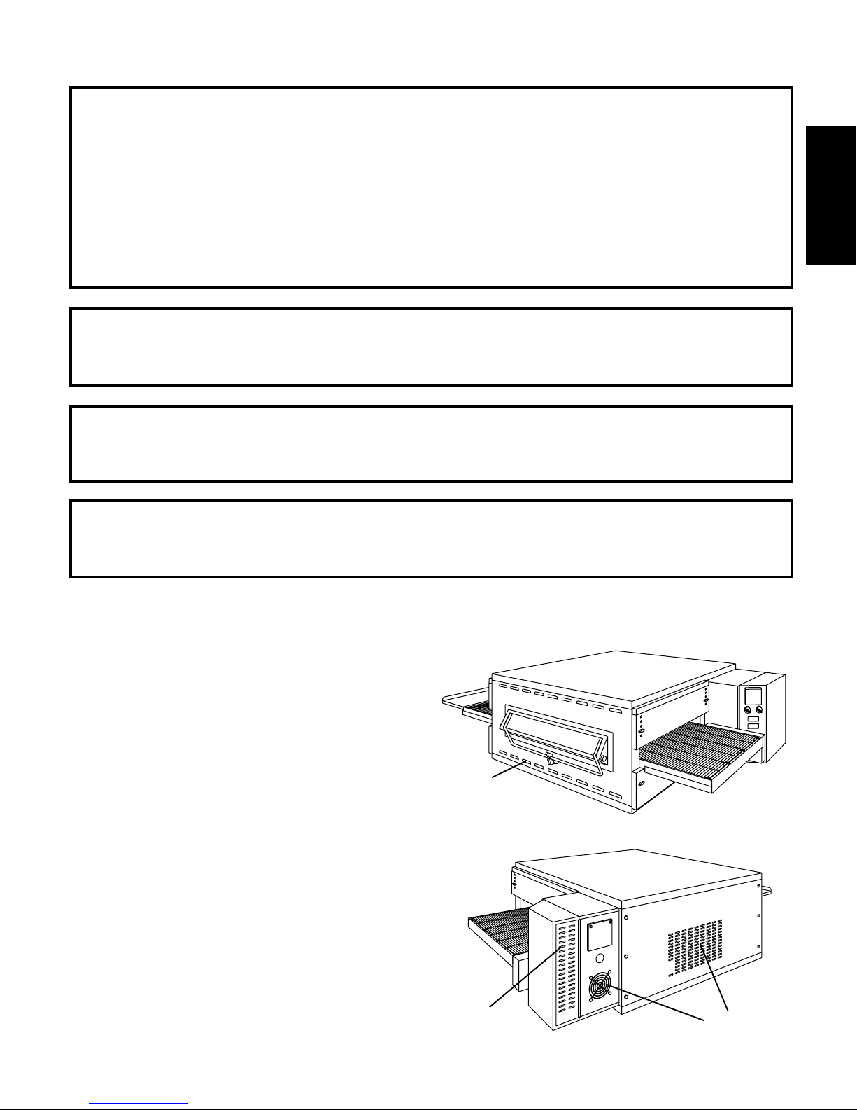
B. Clean ALL of the cooling fan grills and vent openings with a
stiff nylon brush. Refer to Figure 4-1 for the locations of the
grills and vents.
C. Clean the outside of the oven with a soft cloth and mild
detergent.
D. Check that ALL cooling fans are operating properly.
CAUTION
If a cooling fan is not operating correctly, it must be replaced
IMMEDIATELY. Operating the oven without adequate
cooling can seriously damage the oven's internal components.
E. Clean the conveyor belts with a stiff nylon brush. This is
more easily accomplished by allowing the conveyor to run
while you stand at the exit end of the conveyor. Then, brush
the crumbs off the conveyor as it moves.
F. Remove and clean the crumb trays. Be sure to replace the
trays in the same positions from which they were removed,
because they are NOT identical. Refer to Figure 2-12 (in
Section 2, Installation).
G. Clean the window (if so equipped) in place.
Vents on
front panel
of oven
Vents on rear of
machinery
compartment
access panel
21
Figure 4-1 -Cooling Vents and Grills
Grills/vents
on rear of
oven
Page 22
SECTION 4 - MAINTENANCE
II. MAINTENANCE - MONTHLY
A. Check that the oven is cool and the power is disconnected,
as described in the warning at the beginning of this Section.
B. Refer to Part D, Conveyor Installation, in the Installation
ENGLISH
section of this Manual. Then, remove the following components from the oven:
Conveyor exit tray
Crumb trays
Chain cover
End plugs
Conveyor assembly
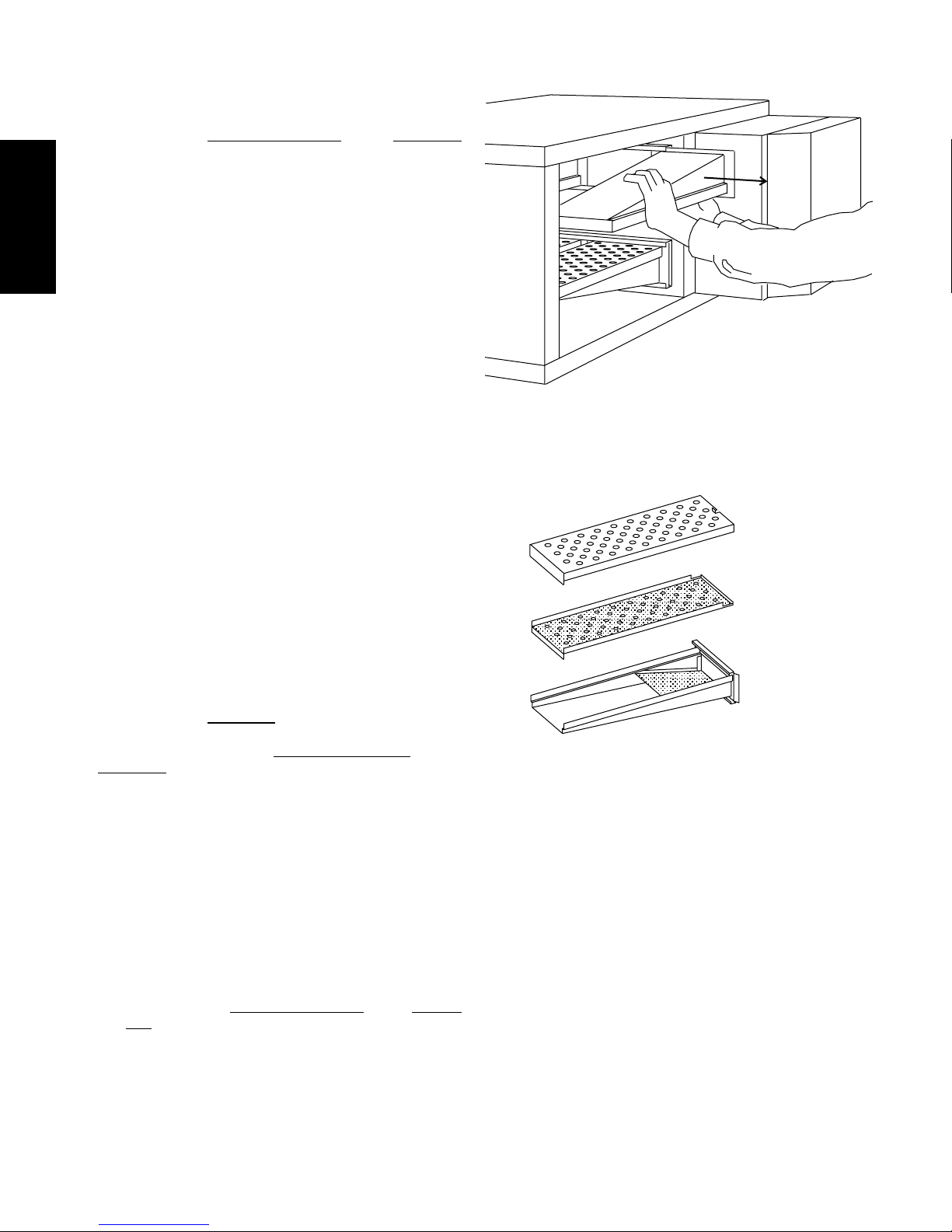
C. Slide the air fingers and blank plates out of the oven, as
shown in Figure 4-2. AS EACH FINGER OR PLATE IS
REMOVED, WRITE A "LOCATION CODE" ON IT WITH A
MARKER to make sure that it can be reinstalled correctly.
Example of markings:
(Top Row) T1 T2 T3 T4
(Bottom Row) B1 B2 B3 B4
D. Disassemble the air fingers. See Figure 4-3. AS EACH
FINGER IS DISASSEMBLED, WRITE THE "LOCATION
CODE" FOR THE FINGER ON ALL THREE OF ITS PIECES.
This will help you in correctly reassembling the air fingers.
CAUTION
Incorrect reassembly of the air fingers will change the
baking properties of the oven.
E. Clean the air finger components and the interior of the
baking chamber using a vacuum cleaner and a damp cloth.
Refer to the boxed warnings at the beginning of this Section
for cleaning precautions.
F. Reassemble the air fingers. Then, replace them in the
oven, using the "location code" as a guide.
G. Install the end plugs on the oven. Then, reinstall the
conveyor.
I. Reattach the drive chain. Replace the chain cover.
J. Check the tension of the conveyor belt as shown in Figure
2-9 (in Section 2,
1-2" (25-50mm). If necessary, adjust the belt tension using
the procedure in Part D (Conveyor Installation) in the
Installation section of this Manual.
K. Replace the crumb trays and exit tray onto the oven.
Installation). The belt should lift between
Figure 4-2 - Removing Air Fingers and Plates
Figure 4-3 - Disassembling the Air Fingers
Outer Plate
Inner plate
Manifold
III. MAINTENANCE - EVERY 3 MONTHS
A. Check that the oven is cool and the power is disconnected,
as described in the warning at the beginning of this Section.
B. Open the machinery compartment access panel. Vacuum
the inside of the compartment using a shop vacuum.
C. Tighten all electrical control terminal screws.
D. Split Belt Disassembly and Cleaning
For split belt ovens ONLY, disassemble, clean and lubri-
cate the conveyor shaft components as described below.
1. Refer to Part D, Conveyor Installation, in the Installation section of this Manual. Then, remove the following
components from the oven:
Conveyor exit tray
Crumb trays
Chain cover
End plugs
Conveyor assembly
2. Remove the master links from each conveyor belt.
Then, roll the belts up along the length of the conveyor
to remove them from the frame.
22
Page 23
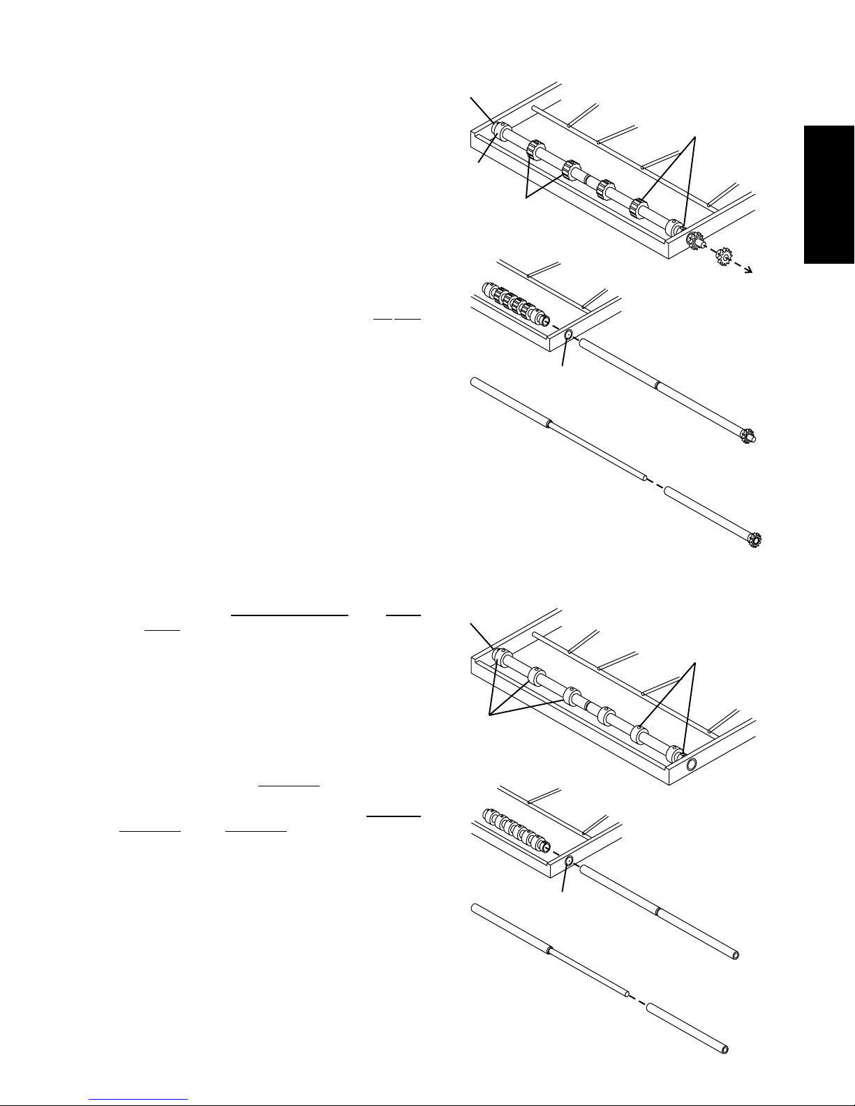
3. Disassemble and clean the drive and idler shafts
using the following procedure.
a. Loosen (DO NOT REMOVE) the set screw on the
outer drive sprocket. Then, slide the drive sprocket
off the end of the drive shaft. See Figure 4-4.
b. Loosen (DO NOT REMOVE) the set screws on all
four steel spacers (2 per shaft), AND on all twelve
conveyor belt sprockets (6 per shaft).
c. Gently work the shaft sections out of the conveyor
frame, removing the conveyor belt sprockets as
necessary. See Figures 4-4 and 4-5.
d. Slide the two sections of each shaft apart.
e. Clean all of the shaft components thoroughly
using a rag. Then, lubricate each solid inner shaft,
AND the interiors of each hollow shaft, using an
FDA-approved light food-grade lubricant. DO NOT
lubricate the shafts using WD40 or a similar
product. This can cause the shafts to wear rapidly.
f. Slide the hollow shaft sections over the solid inner
shafts. Check that the hollow section that has a
drive sprocket attached is placed at the end of the
the drive shaft.
g. Slide the reassembled shafts into the conveyor
frame. As the shafts are replaced, slide the steel
spacers and conveyor belt sprockets onto the
shafts. Refer to Figures 4-4 and 4-5.
h. After the shafts are properly aligned, position the
steel spacers against the ends of the bushings
on the conveyor frame. Tighten the set screws on
the spacers to hold them in place. Leave the
conveyor belt sprockets loose at this time.
i. Replace the outer drive sprocket. Tighten its set
screw to hold it in place.
j. Refer to Part D,
Conveyor Installation, in the Installation section of this Manual to replace the conveyor belt. As you replace the belt, position the
conveyor belt sprockets.
k. After the belt is in place and the sprockets are
correctly positioned, tighten the set screws to hold
the sprockets in place.
4. Reinstall the end plugs and conveyor onto the oven.
5. Reattach the drive chains. Replace the chain cover.
7. Check the tension of the conveyor belt as shown in
Figure 2-9 (in Section 2, Installation). The belt should
lift between 1-2" (25-50mm). If necessary, adjust the
belt tension using the procedure in Part D (Conveyor
Installation) in the Installation section of this Manual.
8. Replace the crumb trays and exit tray onto the oven.
Spacer (2)
Smooth
sprocket (2)
Spacer (2)
Smooth
sprockets (6)
SECTION 4 - MAINTENANCE
Figure 4-5 - Disassembling the drive shaft
2. Loosen set
screws on belt
sprockets and
spacers (8)
Sprockets
w/teeth (4)
1. Remove outer
drive sprocket
Bushing
4. Disassemble,
clean, and
lubricate shafts
3. Slide shafts out
of frame
Figure 4-5 - Disassembling the idler shaft
1. Loosen set
screws on belt
sprockets and
spacers (8)
ENGLISH
23
Bushing
3. Disassemble,
clean, and
lubricate shafts
2. Slide shafts out
of frame
Page 24
SECTION 4 - MAINTENANCE
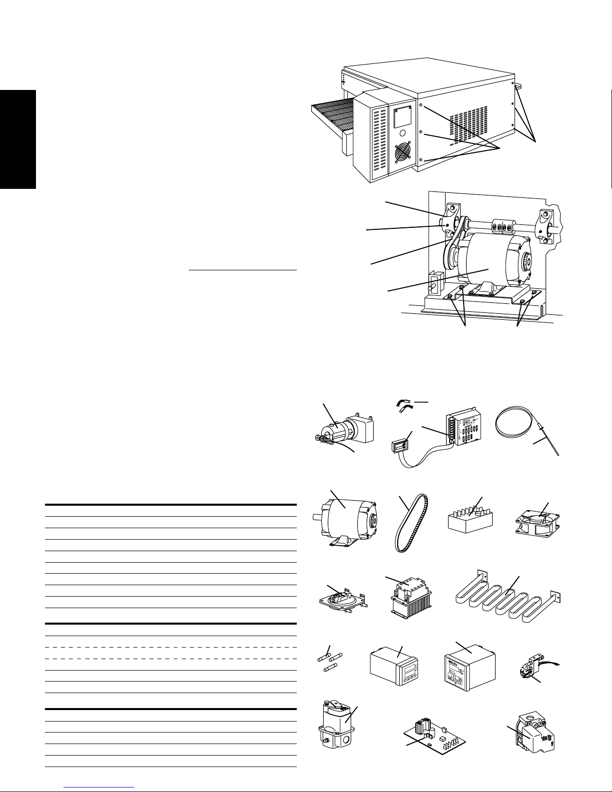
E. Blower Belt
1. Remove the six screws shown in Figure 4-6. Then,
remove the rear panel from the oven.
2. Check the blower belt for the proper 1/4" (6.4mm)
deflection at the center, and for cracking or excessive
ENGLISH
wear. See Figure 4-6. Overtightening the belt will
cause premature bearing failure and possible vibrations. A loose belt may also cause vibrations.
3. If necessary, adjust the tension of the belt by loosening
the four motor mounting bolts. Reposition the motor
as neccessary until the correct 1/4" (6.4mm) deflection
is reached, then tighten the bolts.
F. Lubricating the Blower Fan Bearings
1. Use a grease gun to lubricate the main blower fan
shaft bearings, as shown in Figure 4-6.
When lubricating the bearings:
Use a high-quality NLGI #2, lithium soap grease with
petroleum oil, such as Middleby P/N 17110-0015.
Add the grease slowly until a small bead of grease
is present at the seals.
Excessive greasing may cause harm to the bearing.
2. Manually turn the blower shaft by pulling on the belt to
purge the grease. Wipe off any excess grease.
3. Replace the rear panel onto the oven.
AVOID OVERGREASING.
Figure 4-6 - Rear panel access
Remove six (6)
screws to remove
rear panel
Bearings
(2 total)
Grease fitting
(1 per
bearing)
Blower belt
Blower motor
IV. MAINTENANCE - EVERY 6 MONTHS
A. Check that the oven is cool and the power is disconnected, as
described in the warning at the beginning of this Section.
B. Check for excessive wear on the conveyor drive motor
brushes. The brushes should be replaced if they have
worn to less than 1/4" (6.4mm) in length. Be sure to replace
the brushes in exactly the same position.
C. For gas ovens, inspect and clean the burner nozzle and the
spark electrode assembly.
D. Check the conveyor drive shaft bushings and spacers.
Replace the components if they are worn.
V. KEY SPARE PARTS KIT - Available sepa-
rately. See Figure 4-7.
Item Qty. Part No. Description
1 1 44695 Conveyor Drive Motor w/Pickup Assy.
2 2 30153 Drive Motor Brushes
3 1 37337 Kit, Conveyor Speed Controller
4 1 33985 Kit, Thermocouple
5 1 44687 Motor, Blower
6 1 44685 Belt, Blower
7 1 33983 High Limit Control Module, 230V
8 1 97525 Axial Cooling Fan, 230V
9 1 39530 Air Switch, 230V
ELECTRIC OVENS ONLY:
10 1 44585 Relay and Heat Sink Assembly
11a 1 43094 Heating Element, 208V 8 kW
11b 1 44800 Heating Element, 230V 8 kW
11c 1 45281 Heating Element, 380V 8 kW
12 3 44701 Fuse, 60A
13 1 44783 Kit, Digital Temperature Controller
GAS OVENS ONLY:
14 1 36939 Kit, Digital Temperature Controller
15 1 44802 Pilot Assembly
16 1 41647 Modulating Gas Valve, 1/2"
17 1 31651 Amplifier Board
18 1 44801 Combination Gas Control Valve
24
Loosen four (4) screws to adjust
motor position and belt tension
Fig. 4-7 - Key Spare Parts Kit
1
2
3
4
5
9
12
10
6
13
14
7
8
11
15
16
18
17
Page 25
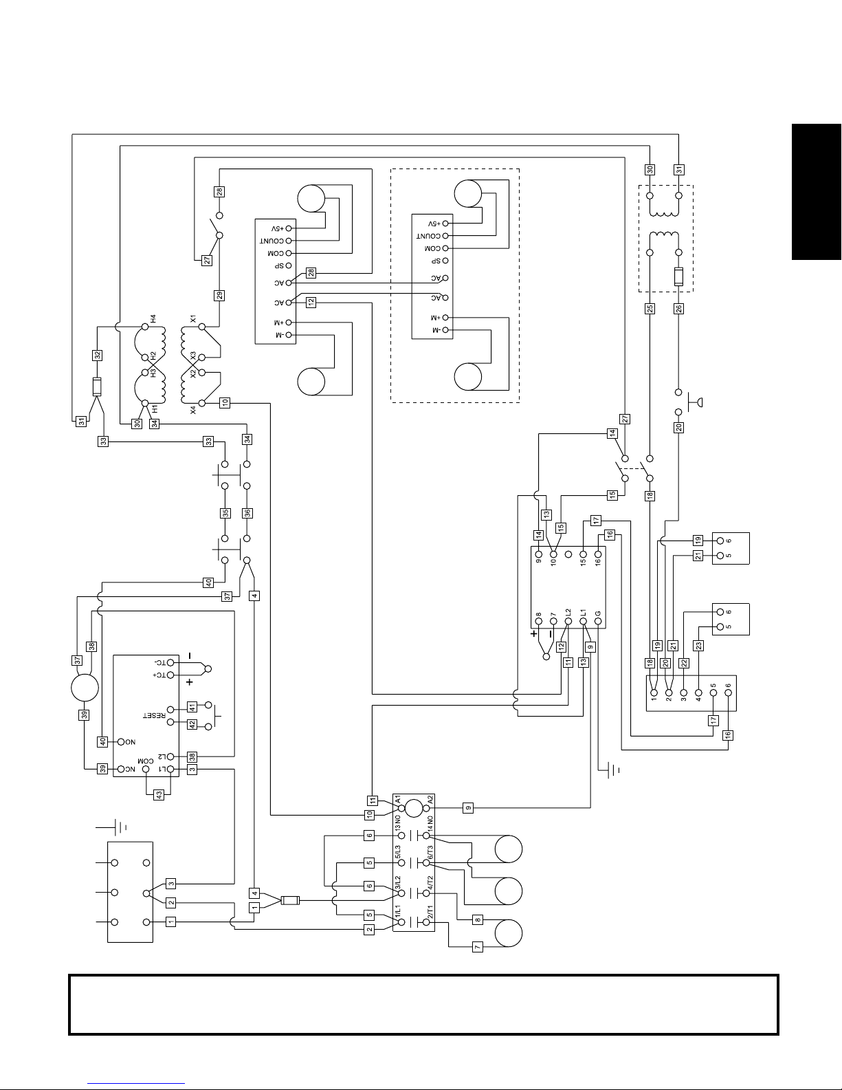
SECTION 5 - ELECTRICAL WIRING DIAGRAMS
Fig. 5-1 - Wiring diagram, PS536 Gas Oven
208/230V, 60 Hz, 1 Ph
PICKUP
SWITCH
CONVEYOR
240V PRI.
120V SEC.
TRANSFORMER
CONVEYOR SPEED CONTROLLER
DRIVE
CIRCUIT BREAKER 2A
MOTOR
SAFETY
SWITCH
COMPARTMENT
SAFETY
SWITCH
MACHINERY
COMPARTMENT
MOTOR
CONVEYOR SPEED CONTROLLER
SPLIT BELT OVENS ONLY
PICKUP
DRIVE
MOTOR
SWITCH
BLOWER
240V PRI.
TRANSFORMER
AIR
SWITCH
PRESSURE
24V SEC.
VALVE
COMBINATION
GAS CONTROL
ENGLISH
CONTROLLER
TEMPERATURE
COUPLE
THERMO-
COUPLE
THERMO-
FAN
COOLING
FAN
COOLING
MOTOR
BLOWER
RESET LAMP
TERMINAL BLOCK
MODULE
CONTROL
HIGH LIMIT
L2 N
L1
RESET
SWITCH
15A
CIRCUIT
BREAKER
CONTACTOR
IMPORTANT
An electrical wiring diagram for the oven is also located inside the machinery compartment.
VALVE
MODULATING
BOARD
AMPLIFIER
25
Page 26
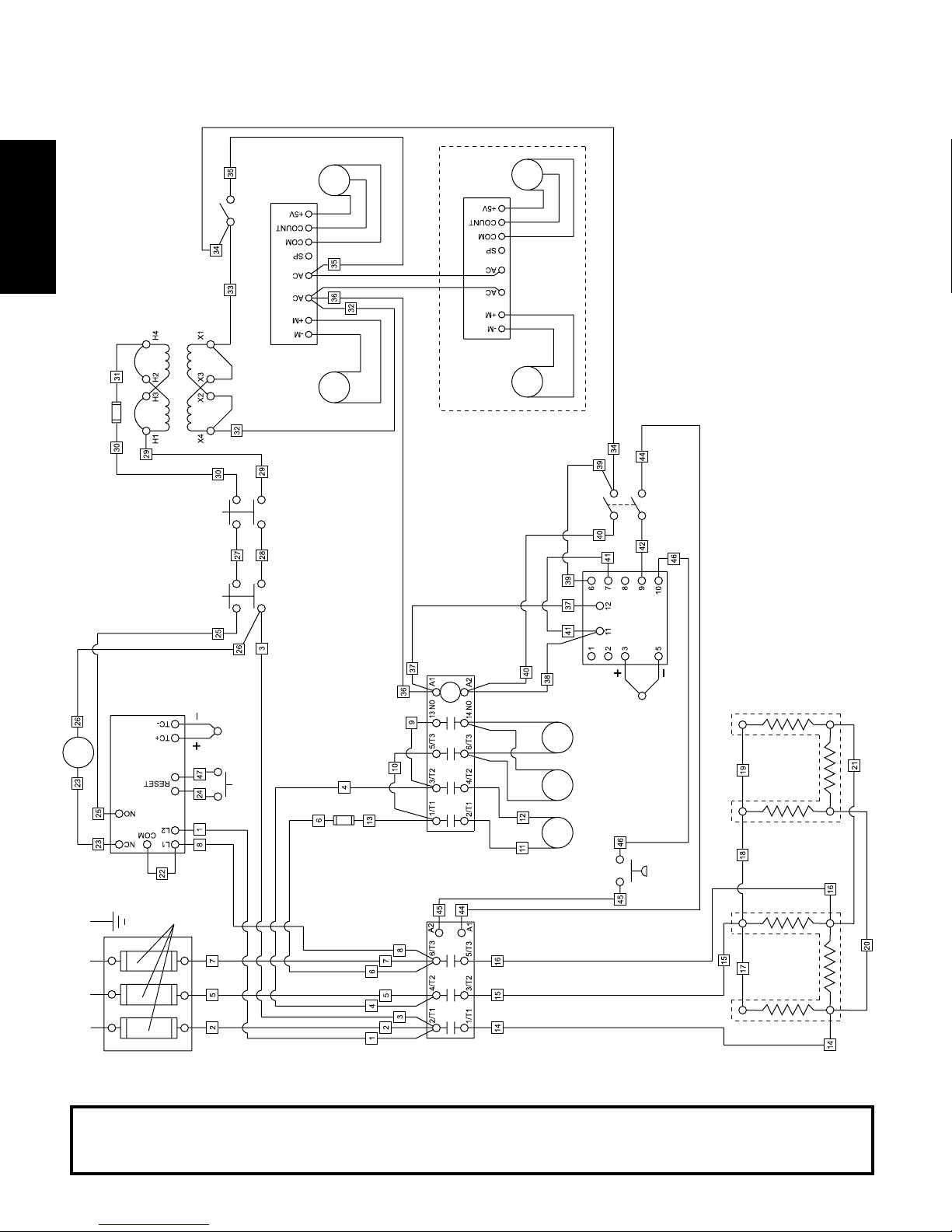
SECTION 5 - ELECTRICAL WIRING DIAGRAMS
ENGLISH
208V PRI.
120V SEC.
TRANSFORMER
2A
CIRCUIT
BREAKER
SWITCH
CONVEYOR
CONVEYOR SPEED CONTROLLER
Fig. 5-2 - Wiring diagram, PS536 Electric Oven
208/230V, 60 Hz, 3 Ph
PICKUP
DRIVE
MOTOR
CONVEYOR SPEED CONTROLLER
SPLIT BELT OVENS ONLY
PICKUP
DRIVE
MOTOR
RESET LAMP
MODULE
CONTROL
HIGH LIMIT
60A
FUSES
COUPLE
THERMO-
RESET
SWITCH
MOTOR
SAFETY
SWITCH
COMPARTMENT
SAFETY
SWITCH
MACHINERY
COMPARTMENT
15A
CIRCUIT
BREAKER
RELAY
3-PHASE
CONTACTOR
FAN
COOLING
FAN
COOLING
MOTOR
BLOWER
SWITCH
BLOWER
COUPLE
THERMO-
AIR
TEMPERATURE CONTROLLER
SWITCH
PRESSURE
8kW
HEATER
L2 L3
TERMINAL BLOCK
L1
An electrical wiring diagram for the oven is also located inside the machinery compartment.
IMPORTANT
26
8kW
HEATER
Page 27

Fig. 5-2 - Wiring diagram, PS536 Electric Oven
380V, 50 Hz, 3 Ph
SECTION 5 - ELECTRICAL WIRING DIAGRAMS
2A
CIRCUIT
BREAKER
208V PRI.
120V SEC.
TRANSFORMER
SWITCH
CONVEYOR
CONVEYOR SPEED CONTROLLER
PICKUP
DRIVE
MOTOR
MOTOR
SAFETY
SWITCH
COMPARTMENT
SAFETY
SWITCH
MACHINERY
COMPARTMENT
SPLIT BELT OVENS ONLY
CONVEYOR SPEED CONTROLLER
DRIVE
PICKUP
MOTOR
SWITCH
BLOWER
ENGLISH
RESET LAMP
TERMINAL BLOCK
CONTACTOR
TEMPERATURE CONTROLLER
COUPLE
60A
THERMO-
RESET
SWITCH
15A
CIRCUIT
BREAKER
RELAY
3-PHASE
MODULE
CONTROL
HIGH LIMIT
N
L2 L3
L1
FUSES
FAN
COOLING
FAN
COOLING
MOTOR
BLOWER
COUPLE
THERMO-
AIR
SWITCH
PRESSURE
8kW
HEATER
8kW
HEATER
An electrical wiring diagram for the oven is also located inside the machinery compartment.
IMPORTANT
27
Page 28

ENGLISH
page 1
FRANÇAIS
page 29
ESPAÑOL
página 57
Middleby Cooking Systems Group 1400 Toastmaster Drive Elgin, IL 60120 USA (847)741-3300 FAX (847)741-4406
24-Hour Service Hotline: 1-(800)-238-8444
www.middleby.com
28
Page 29

PS536
À gaz et électrique
Exportation intérieure et standard
Anglais/FRANÇAIS/Espagnol
N/P 44727
Rév. C C1 2/01
page 1
ANGLAIS
page 29
FRANÇAIS
Fours électriques et à gaz,
modèle PS536
Modèles :
PS536
MANUEL DINSTALLATION
ET DE FONCTIONNEMENT
pour fours destinés à lexportation intérieure
et standard
© 2001 Middleby Marshall, Inc.
est une marque déposée de Middleby Marshall, Inc. Tous droits réservés.
Middleby Cooking Systems Group 1400 Toastmaster Drive Elgin, IL 60120 (847)741-3300 Télécopieur (847)741-4406
Combinaisons :
Four unique
Four double (superposition de deux éléments)
Four triple (superposition de trois éléments)
PS536 À
GAZ
PS536
ÉLECTRIQUE
Modèles 208/230V
PS536
ÉLECTRIQUE
Modèles 380V
29
page 57
ESPAGNOL
Page 30

AVIS :
Ce manuel dinstallation et dutilisation doit être fourni à lutilisateur. Lopérateur du four devrait être familier
avec les commandes du four et son fonctionnement.
Ce manuel doit être placé près du four, être bien visible et facilement accessible.
Les fours peuvent être alimentés SOIT en gaz naturel, SOIT en gaz propane, comme lindique la plaque de
série. Si les normes locales et nationales le permettent, il est possible de convertir un four fonctionnant au gaz
naturel en un four fonctionnant au gaz propane, et vice versa. Cette conversion requiert linstallation de la
trousse appropriée de conversion du gaz Middleby Marshall par un technicien agréé.
Il est recommandé de se procurer un contrat dentretien auprès dun technicien agréé par Middleby Marshall.
AVERTISSEMENT
AFFICHEZ, DE MANIÈRE VISIBLE, LE NUMÉRO DE TÉLÉPHONE DURGENCE DE VOTRE FOURNISSEUR
FRANÇAIS
Les directives à suivre en cas dodeur de gaz sont disponibles auprès dun fournisseur de gaz local. Si vous
détectez une odeur de gaz, composez immédiatement le numéro durgence de votre fournisseur de gaz local.
DE GAZ LOCAL ET LES DIRECTIVES À SUIVRE EN CAS DODEUR DE GAZ.
Le fournisseur a le personnel et léquipement nécessaire pour corriger le problème.
DIRECTIVES IMPORTANTES DE SÉCURITÉ
Nentreposez pas ou nutilisez pas dessence, de substances produisant des
vapeurs inflammables ou de liquides inflammables à proximité de cet appareil ou de
tout autre appareil.
AVERTISSEMENT :
Une installation, un réglage, un entretien ou laltération incorrects de
lappareil peuvent causer des dommages matériels, des blessures et
même la mort. Lisez les directives dinstallation, de fonctionnement et
dentretien dans leur intégralité avant dinstaller ou de réparer cet
appareil.
IMPORTANT
Le schéma de câblage sappliquant à ce four est situé à lintérieur du compartiment des
composants.
IMPORTANT
Le consommateur est responsable de signaler toute avarie apparente ou non
apparente au transporteur. Conservez tout le matériel dexpédition jusquà ce que
vous soyez assuré que le matériel na pas subi davarie.
AVIS : VEUILLEZ CONTACTER UN TECHNICIEN AGRÉÉ PAR MIDDLEBY MARSHALL POUR LENTRETIEN ET LES
RÉPARATIONS. UN RÉPERTOIRE DES CENTRES DE SERVICE AGRÉÉS EST FOURNI AVEC VOTRE FOUR.
AVIS : Lutilisation de pièces autres que les pièces fabriquées à lusine de Middleby Marshall décharge le fabricant de
toute obligation et de toute responsabilité inhérente à la garantie.
AVIS : Middleby Marshall (fabricant) se réserve le droit de modifier les spécifications à tout moment.
AVIS : La garantie de léquipement nest valide que si linstallation, la mise en marche, et la démonstration du four sont
faites sous la surveillance dun installateur qualifié de lusine.
Conservez ce manuel pour référence ultérieure
Middleby Cooking Systems Group 1400 Toastmaster Drive Elgin, IL 60120 USA (847)741-3300 Télécopieur (847)741-4406
Service dassistance téléphonique 24 heures : 1-(800)-238-8444
www.middleby.com
30
Page 31

TABLE DES MATIÈRES
page page
SECTION 1 - DESCRIPTION .................................................. 32
I. UTILISATIONS DU FOUR .......................................32
II. COMPOSANTS DU FOUR ......................................32
A. Fenêtre............................................................. 32
B. Plateau de sortie du transporteur................... 32
C. Gardes ............................................................. 32
D. Panneaux latéraux...........................................32
E. Tableau de commande .................................. 32
F. Panneau de service du compartiment des
composants .................................................... 32
G. Plaque de série ............................................... 32
H. Moteur dentraînement du transporteur .......... 32
I. Plateaux à miettes...........................................32
J. Transporteur ....................................................32
K. Brûleur à gaz ou éléments chauffants ........... 32
L. Souffleries ....................................................... 32
M. Conduits dair .................................................. 32
III. SPÉCIFICATIONS DU FOUR ................................. 32
A. Dimensions ..................................................... 32
B. Spécifications générales ................................32
C. Spécifications électriques - Fours
électriques .......................................................33
D. Spécifications électriques - Fours à gaz ........33
E. Spécifications des orifices à gaz et
de pression ..................................................... 33
SECTION 2 - INSTALLATION................................................. 34
I. TROUSSE DINSTALLATION ................................. 35
II. TROUSSE DE PLAQUE DE POSE......................... 35
III. SYSTÈME DE VENTILATION .................................. 36
A. Exigences ........................................................36
B. Recommandations ......................................... 36
C. Autres considérations pour la ventilation....... 36
IV. ASSEMBLAGE ......................................................... 37
A. Panneau supérieur et plaque de pose .......... 37
B. Superposition .................................................. 38
C. Installation du câble de retenue ..................... 38
D. Installation du transporteur ............................ 39
V. ASSEMBLAGE FINAL .............................................. 40
VI. ALIMENTATION EN ÉLECTRICITÉ ........................ 41
A. Renseignements supplémentaires - Fours
à gaz ................................................................ 41
B. Renseignements supplémentaires - Fours
électriques .......................................................41
C. Raccordement .................................................41
VII. ALIMENTATION EN GAZ ......................................... 41
A. Recommandations de plomberie brute pour
lalimentation en gaz .......................................42
B. Raccordement .................................................42
C. Conversion du gaz .......................................... 42
SECTION 3 - FONCTIONNEMENT .......................................... 43
I. EMPLACEMENT ET DESCRIPTION DES
COMMANDES ......................................................... 43
A. Bouton de commande « BLOWER »
(soufflerie)(
B. Bouton de commande « CONVEYOR »
(transporteur)( ) ......................................... 43
C. Régulateur de vitesse de transporteur .......... 43
D. Régulateur de température numérique ......... 43
E. Contacteur de sécurité du panneau de service du
compartiment des composants ..................... 43
II. FONCTIONNEMENT NORMAL, PAS-À-PAS .......... 44
A. Procédure quotidienne de mise en marche.. 44
B. Procédure quotidienne de mise en arrêt ....... 45
III. CONSULTATION RAPIDE : RÉGULATEUR DE
TEMPÉRATURE NUMÉRIQUE ............................... 46
IV. CONSULTATION RAPIDE : RÉSOLUTION DE
PROBLÈMES .......................................................... 48
SECTION 4 - ENTRETIEN ....................................................... 49
I. ENTRETIEN - QUOTIDIEN .....................................49
II. ENTRETIEN - MENSUEL ....................................... 50
III. ENTRETIEN - TRIMESTRIEL ................................. 50
IV. ENTRETIEN - SEMESTRIEL .................................. 52
V. TROUSSE DE PIÈCES DE RECHANGE
ESSENTIELLES ...................................................... 52
SECTION 5 - SCHÉMAS DE CÂBLAGE .................................. 53
I. SCHÉMA DE CÂBLAGE, FOUR À GAZ PS536
208/230 V, 60 Hz, 1 Ph ...........................................53
II. SCHÉMA DE CÂBLAGE, FOUR ÉLECTRIQUE
PS536, 208/230 V, 60 Hz, 3 Ph ..............................54
III. SCHÉMA DE CÂBLAGE, FOUR ÉLECTRIQUE
PS536, 380 V, 50 Hz, 3 Ph ..................................... 55
) ................................................ 43
FRANÇAIS
31
Page 32

SECTION 1 - DESCRIPTION
I. UTILISATIONS DU FOUR
Les fours de série PS536 peuvent être utilisés pour faire cuire une
grande variété de produits alimentaires, tels que la pizza, les
produits similaires à la pizza, les biscuits, les sandwichs et autres.
II. COMPOSANTS DU FOUR - Figure 1-1.
A. Fenêtre (en option) : Permet à lutilisateur de voir les aliments
qui sont dans la chambre de cuisson et davoir accès à la chambre
de cuisson.
B. Plateau de sortie du transporteur: Empêche les aliments de
tomber lorsque le transporteur fonctionne.
C. Gardes (en option) : Peuvent être ajustées à différentes
hauteurs pour prévenir la perte de chaleur.
D. Panneaux latéraux : Permettent davoir accès à lintérieur du
FRANÇAIS
four.
E. Tableau de commande : Emplacement des commandes de
fonctionnement du four. Reportez-vous à la rubrique,
Fonctionnement, de la section 3 pour obtenir plus de détails.
F. Panneau de service du compartiment des composants :
Permet davoir accès aux composants situés à lintérieur du four.
Ce compartiment ne contient pas de pièce pouvant être entretenue
ou réparée par lutilisateur.
G. Plaque de série : Fournit les spécifications du four relatives à
linstallation et au fonctionnement. Reportez-vous à la rubrique,
Installation, de la section 2 pour obtenir plus de détails.
H. Moteur dentraînement du transporteur : Met le transporteur
en mouvement.
I. Plateaux à miettes : Reçoivent les miettes et les autres aliments
qui passent à travers la bande transporteuse du transporteur. On
trouve un plateau à miettes en dessous de chaque transporteur.
J. Transporteur : Fait passer les aliments dans le four.
Non illustrés :
K. Brûleur à gaz (fours à gaz) ou éléments chauffants (fours
électriques): Chauffe(nt) lair qui est ensuite projeté vers les
conduits dair par les souffleries.
L. Souffleries : Ventilateurs qui projettent de lair chaud du brûleur
à gaz ou des éléments chauffants aux conduits dair.
M. Conduits dair : Projettent de lair chaud sur les aliments.
Figure 1-1 - Composants du four
B
A
EDC
G
H
I
J
F
III. SPÉCIFICATIONS DU FOUR
Tableau 1-1: Dimensions
Hauteur hors-tout: four simple avec pieds de 17-1/2" (446 mm) 43-1/2" (1.105 mm)
four double avec pieds de 17-1/2" (446 mm) 63" (1.600 mm)
four triple avec pieds de 6" (152 mm) 71" (1.803 mm)
Profondeur hors-tout: sans fenêtre avant 39-3/4" (1.010 mm)
avec fenêtre avant 43" (1.092 mm)
Longueur hors-tout : sans plateau de sortie installé 60" (1.524 mm)
avec plateau de sortie installé 68-1/4" (1.734 mm)
Longueur de la chambre de cuisson 36" (914 mm)
Largeur du transporteur: Bande transporteuse simple 20" (508 mm)
Bande transporteuse divisée 2 x 9-1/2" (241 mm)
Largeur du transporteur 60" (1.524 mm)
Dégagements minimums recommandés:
De larrière du four au mur 3" (76 mm)
De lextrémité du transporteur, côté commande, au mur 18" (457 mm)
De lextrémité du four, sans commande, au mur 3" (76 mm)
Tableau 1-2 : Spécifications générales (par cavité de four)
Poids 400 lbs. (182 kg)
Débit calorifique nominal : Fours à gaz naturel 50.000 BTU (12.600 kcal, 14,65 kW/h.)
Fours au gaz propane 45.000 BTU (11.340 kcal, 13,19 kW/h)
Fours électriques 16 kW
Température de fonctionnement 200-600°F (93-316°C)
Temps de préchauffage 25 minutes
32
Page 33

SECTION 1 - DESCRIPTION
Tableau 1-3 : Spécifications électriques - pour tous les fours électriques (par cavité de four)
Tension circuit de Appel de courant
Souffl. princip. commande Phase Fréq. L1 L2 L3 N Calibre kW Pôles Câblage
208 V Commande de vitesse de transp., 3 Ph 60 Hz 50 A 50 A 50 A 16,0 kW 4 pôles 4 fils
moteur dentraînement, contacteur, à 208 V (3 chauds,
& commande de temp.à 120 V; 1 masse)
230 V Commande de vitesse de transp., 3 Ph 60 Hz 45 A 45 A 45 A 16,0 kW 4 pôles 4 fils
moteur dentraînement, contacteur, à 230 V (3 chauds,
& commande de temp.à 120 V; 1 masse)
380 V * Commande de vitesse de transp., 3 Ph 50 Hz 25 A 25 A 28 A 5 A 16,0 kW 4 pôles 5 fils (3 chauds,
moteur dentraînement, contacteur, à 380 V 1 neut., 1 masse)
& commande de temp. à 120 V;
* Le modèle 380 V nest pas approuvé par
Tension
toute autre 208 V
toute autre 230 V
éléments chauffants 380 V;
toute autre 240 V
ou .
Tableau 1-4 : Spécifications électriques - pour tous les fours à gaz (par cavité de four)
Tension circuit de Appel de
Souffl. princip. commande Phase Fréq. courant Pôles Câblage
208/240 V Commande de vitesse de transp., 1 Ph 60 Hz 6 A 3 pôles 4 fils (2 chauds,
moteur dentraînement, contacteur, 1 neut., 1 masse)
& commande de temp.à 120 V;
Tension
toute autre 208-240 V
FRANÇAIS
Tableau 1-5 : Spécifications des orifices de gaz et de pression (par cavité de four)
Type de gaz D.I. de lorifice principal D.I. de lorifice du pilote Pression de canalisation d'admission (orifice)
Naturel 0,0935" (2,3749 mm, mèche n°42) 0,018" (0,46 mm) 4-7" C.E. (9,95-17,4 mbar) * 3.5" C.E. (8,7 mbar)
Propane 0,0520" (1,3208 mm, mèche n°55) 0,018" (0,46 mm) 11-14" C.E. (27,4-34,9 mbar) * 10,5" C.E. (24,9 mbar)
* Les pressions dalimentation en gaz présentées ici correspondent au pressions utilisées pour les fours installés en Amérique du Nord.
Les exigences en matière de pressions dalimentation en gaz dans dautres pays dépendent du type de gaz utilisé localement et des
réglementations locales applicables.
Pression
IMPORTANT
Des renseignements supplémentaires sur lélectricité se trouvent sur la plaque de série du four et sur le schéma de câblage
situé à lintérieur du compartiment des composants.
33
Page 34

SECTION 2 - INSTALLATION
AVERTISSEMENT Pour les fours à gaz, après des conversions, réajustements, travaux
dentretien sur le four:
Effectuez un essai détanchéité du gaz.
Vérifiez si lapprovisionnement en air est adéquat.
Vérifiez si lalimentation en gaz et la combustion sont adéquates.
Assurez-vous que le système de ventilation est en fonctionnement.
AVERTISSEMENT
Pour les fours électriques, après des conversions, réajustements, travaux dentretien sur le four,
assurez-vous que le système de ventilation est en fonctionnement (le cas échéant).
FRANÇAIS
Le four doit être installé sur un revêtement de sol régulier et ininflammable et tout mur adjacent
doit être ininflammable. Les dégagements minimum recommandés sont spécifiés dans la section
Nobstruez pas le débit de lair de combustion ou de ventilation en provenance du four ou en direction du
four. Il ne doit pas y avoir dobstructions autour ou en dessous du four. Toute modification de constructions
Le dégagement doit être suffisant entre le four et les structures combustibles. Il doit également permettre
Le schéma de câblage sappliquant à ce four est situé à lintérieur du compartiment des composants.
AVERTISSEMENT
Dégagez le site dexploitation de lappareil de tout produit combustible.
AVERTISSEMENT
Description de ce manuel.
AVERTISSEMENT
dans la zone où se trouve le four ne peut pas affecter lapprovisionnement dair au four.
MISE EN GARDE
Pour plus de détails concernant linstallation, contactez votre technicien local agréé.
REMARQUE
lentretien et le fonctionnement.
REMARQUE
Tous les aspects touchant à linstallation du four, notamment lemplacement, les branchements au secteur et les
exigences de ventilation doivent être conformes aux normes locales et nationales en vigueur. Ces normes remplacent
les exigences et les directives fournies dans ce manuel.
Aux États-Unis, linstallation du four doit être conforme aux normes locales. En labsence de telles normes, les
installations de fours à gaz doivent être conformes au «National Fuel Gas Code», ANSI Z223.1. Lors de linstallation,
le four doit être mis à la terre selon les normes locales ou, en labsence de telles normes, selon le «National Electrical
Au Canada, linstallation du four doit être conforme aux normes locales. En labsence de telles normes, les installa-
tions de fours à gaz doivent être conformes au «Natural Gas Installation Code», CAN/CGA-B149.1 ou au «Propane
Gas Installation Code », CAN/CGA-B149.2, selon le cas. Lors de linstallation, le four doit être mis à la terre selon les
normes locales ou, en labsence de telles normes, selon le «Canadian Electrical Code» CSA, C22.2.
En Australie, linstallation du four doit être conforme à toutes les exigences de lautorité statutaire appropriée. Les
installations de fours à gaz doivent se conformer au «AGA Code» AG601.
REMARQUE
REMARQUE
Code» (NEC) ou ANSI/NFPA70.
REMARQUE
REMARQUE
34
Page 35

Fig. 2-1 - Trousse dinstallation
SECTION 2 - INSTALLATION
3
7
1
2
8a 8b
11
6
14
10
FRANÇAIS
13
9
12
15
5
4
1
16
17
18
I. TROUSSE DINSTALLATION - Figure 2-1
Article Four unique Four double Four triple Pièce N° Description
1 1 2 3 42882 Panneau supérieur
2 2 2 2 220352 Vis, tête cylindrique large N° 10 x 2" (panneau supérieur avant)
3 2 2 2 3A80A8801 Vis, tête cylindrique large N° 10 x 2" (panneau supérieur arrière)
4 1 2 44837 Panneau de superposition
5 1 2 44918 Isolation, panneau de superposition, pré-coupé
6 4 8 4111A8815 Vis, tête hexagonale N° 10-32 x 1/2" (panneaux de superposition)
7 1 1 1 42893 Plaque de pose
8a 4 4 42890 Pied ajustable de 17-1/2" (445 mm), pour fours simples et doubles
8b 4 44799 Pied ajustable de 6" (152 mm), pour fours triples
9 2 2 2 22290-0009 Roulette pivotante, avec plaque plate et frein
10 2 2 2 22290-0010 Roulette pivotante, avec plaque plate (pas de frein)
11 1 1 1 21392-0004 Anneau, 3/4"
12 31 31 31 220373 Vis hex., 3/8-16 x 1"
13 32 32 32 21416-0001 Rondelle plate, 3/8"
14 32 32 32 21422-0001 Rondelle darrêt, 3/8"
15 1 1 1 22450-0228 Câble de retenue
16 1 2 3 22361-0001 Tuyau de gaz
16 1 1 1 44727 Manuel dinstallation et dutilisation, Fours à gaz et électriques
17 1 1 1 1002040 Répertoire des centres de service agréés par Middleby Marshall
Qté Qté Qté
PS536
35
Page 36

SECTION 2 - INSTALLATION
II. SYSTÈME DE VENTILATION
IMPORTANT
Lorsque les normes nationales ou
locales exigent linstallation
déquipement dextinction des incendies
ou déquipement supplémentaire,
ninstallez PAS léquipement directement
sur le four.
LINSTALLATION DE TEL ÉQUIPEMENT
SUR LE FOUR PEUT :
FRANÇAIS
ANNULER LES HOMOLOGATIONS
DES ORGANISMES
RESTREINDRE LACCÈS AUX
SERVICES
MENER À UNE AUGMENTATION DES
DÉPENSES DENTRETIEN POUR
LUSAGÉ
A. Exigences
MISE EN GARDE
Les installations de fours à gaz
ventilation à commande mécanique avec détection dair de
ventilation électrique.
Lutilisation dun système de ventilation à commande
mécanique est FORTEMENT RECOMMANDÉE dans le cas de
linstallation dun four électrique.
LE PROPRIÉTAIRE DU FOUR EST RESPONSABLE DE LA
VENTILATION APPROPRIÉE DU FOUR.
NÉCESSITENT un système de
B. Recommandations
NOTEZ QUE LES DIMENSIONS DE LA HOTTE INDIQUÉES À
LA FIGURE 2-2
LORS DE LINSTALLATION DUN SYSTÈME DE VENTILATION,
LES NORMES LOCALES, NATIONALES ET INTERNATIONALES
DOIVENT ÊTRE RESPECTÉES. TOUTES LES NORMES
LOCALES ET NATIONALES EN VIGUEUR REMPLACENT LES
RECOMMANDATIONS CONTENUES DANS CE MANUEL.
Le débit dair séchappant du système de ventilation peut varier
selon la configuration du four et la conception de la hotte.
Consultez le fabricant de la hotte ou un technicien en ventilation
pour connaître ces spécifications.
Pour éviter de créer une pression négative dans la cuisine, lair
expulsé doit être remplacé. La chaleur excessive causée par
la pression négative dans la cuisine peut causer autant de
problèmes pour les composants du four que labsence de
ventilation. Lutilisation du système de chauffage, de ventilation
et de climatisation (CVCA) est la meilleure façon de ventiler la
pièce. Il est alors possible de régler la température de lair en
fonction de la saison. Il est également possible daérer la pièce
depuis lextérieur du bâtiment, mais les variations de
températures extrêmement froides ou chaudes selon les
saisons peuvent être nuisibles.
REMARQUE : Lair de retour en provenance du système à
commande mécanique ne doit pas être dirigé dans louverture
de la chambre de cuisson. Le rendement du four serait affecté.
C. Autres considérations pour la ventilation
Le recours à un technicien ou à un spécialiste en ventilation
peut savérer nécessaire dans le cas demplacements, de
situations ou de problèmes particuliers.
Une ventilation inadéquate peut affecter le rendement du
four.
Il est recommandé de faire vérifier le système de ventilation
et les conduites aux intervalles spécifiés par le fabricant de
hotte, le technicien ou le spécialiste CVCA.
NE SONT QUE DES RECOMMANDATIONS.
12" (305 mm)
minimum
2" (51 mm)
minimum
Fig. 2-2 - Système de ventilation
12" (305 mm)
minimum
8" (203 mm)
minimum
36
1" (25 mm)
minimum
Page 37

III. ASSEMBLAGE
A. Panneau supérieur et plaque de pose
1. Installez les quatre pieds ajustables dans la plaque de
pose à laide de vis de 3/8"-16x1", de rondelles plates de
3/8", et de rondelles darrêt de 3/8", fournies dans la
trousse dinstallation de la plaque de pose. Voir Figure 2-
3. Assurez-vous que les côtés finis de chaque pied
ajustable sont orientés vers lextérieur.
Un pied arrière devrait être attaché à laide de trois vis de
3/8"-16 x 1" et dun anneau de 3/4", comme illustré à la
Figure 2-3. Cet anneau sert de point dattache au câble de
retenue (voir Partie C,
2. Installez une roulette dans chaque pied ajustable, comme
le démontre la Figure 2-4. Utilisez les vis de 3/8"-16x1", les
rondelles plates de 3/8" , et les rondelles darrêt de 3/8"
fournies dans la trousse dinstallation. Les roulettes
blocantes doivent être installées à lAVANT du four. Les
roulettes non blocantes doivent être installées à lARRIÈRE
du four.
3. Mettez le panneau supérieur en place sur la cavité de four
du haut à laide des vis se trouvant dans la trousse
dinstallation de la plaque de pose, comme le démontre la
Figure 2-4.
4. Installez la cavité de four du bas sur la plaque de pose.
Vérifiez que lanneau soudé à la plaque fait face à larrière
du four.
Vis N°10 x 2"
sattachent à
larrière du
panneau
supérieur
Installation du câble de retenue).
Figure 2-4 Installation du panneau supérieur et de la plaque de pose
SECTION 2 - INSTALLATION
Figure 2-3 Installation du pied ajustable et des roulettes
Côtés finis du
pied ajustable
sont orientés vers
lextérieur.
Rondelle
plate 3/8"
Rondelle
darrêt 3/8"
Vis hex.
3/8"-16 x 1"
Anneau 3/4" (19 mm)
(coin intérieur dun
pied ajustable
arrière
seulement)
Rondelle
plate de
3/8"
Rondelle
darrêt
de 3/8"
Roulettes blocantes -
AVANT du four
Roulettes non blocantes -
ARRIÈRE du four
Vis hex 3/8"-16 x 1"
Cavité de four
du bas
FRANÇAIS
Vis N°10 x 1"
sattachent à
lavant du
panneau
supérieur
Plaque de pose
assemblée
Cavité de four
du haut
37
Page 38

SECTION 2 - INSTALLATION
B. Superposition
Figure 2-5 Assemblage des entretoises dempilage
Pour les fours simples, passez à la Partie C, Installation
du câble de retenue. Pour les fours doubles et triples,
passez à létape 1 ci-dessous.
1. Montez la/les entretoise(s) dempilage comme le démontre
la Figure 2-5. Une entretoise par four double est fournie,
alors que deux entretoises sont fournies pour les fours
triples.
2. Placez une des entretoises assemblées au-dessus de la
cavité de four du bas, en vous assurant que lisolation est
orientée vers le haut.
3. Placez la cavité de four centrale (pour les fours triples) ou
la cavité de four du haut (pour les fours doubles) au-
FRANÇAIS
dessus de lentretoise. Assurez-vous que les quatre côtés
de lentretoise débordent de la base du four et que le four
est à niveau et bien encré. Reportez-vous à la Figure 2-6.
4. Pour les fours triples, répétez les étapes 2 et 3 pour
installer la cavité de four du haut.
Figure 2-6 Empilage
Vis hexagonales,
Isolation de 1-1/2"
(38 mm)
dépaisseur,
pré-découpée
10-32 x 1/2"
Panneau de
superposition,
P/N 44837
Panneau
supérieur,
P/N 42882
C. Installation du câble de retenue
Puisque le four est équipé de roulettes, un câble de retenue doit
être installé pour limiter le mouvement de lappareil sans
dépendre du connecteur et du dispositif de débranchement
rapide ou des tuyaux associés. Une extrémité du câble est
encrée à lanneau sur lun des pieds ajustables arrière, lautre
extrémité étant encrée au mur. Reportez-vous à la Figure 2-7.
Entretoise
assemblée
(isolation
orientée
vers le
haut)
Après avoir fixé le câble de retenue, mettez le four dans son
emplacement définitif. Ensuite, verrouillez les deux roulettes
avant.
Figure 2-7 - Installation du câble de retenue
Assemblage du
Anneau de
3/8"-16 x 1"
sur le pied
ajustable
arrière
câble de retenue
Anneau de
3/4" (19 mm)
Paroi de la
structure
38
Page 39

D. Installation du transporteur
1. Dépliez le cadre du transporteur de façon à ce quil soit à
plat sur le sol. Tout en dépliant le cadre, vérifiez que les
chevilles de centrage illustrées à la Figure 2-8 se calent
dans les fentes du support.
2. Reportez-vous à la Figure 2-8. Notez les emplacements
des quatre vis de serrage (2 par côté) dans les fentes des
supports. Desserrez ces vis pour pouvoir correctement
ajuster la tension du transporteur.
3. Soulevez la bande transporteuse dans la direction opposée
au cadre, comme illustré à la Figure 2-8, pour vérifier la
tension de la bande transporteuse. La bande transporteuse
devrait pouvoir être soulevée de 1 à 2 po (25-50 mm).
Sil savère nécessaire de devoir ajuster la tension de la
bande, pressez ou poussez doucement sur les deux
sections du cadre du transporteur pour quelles soient
plus proches ou plus éloignées, le cas échéant. Revérifiez ensuite la tension de la bande transporteuse.
Répétez cette étape au besoin, jusquà obtention de la
tension désirée.
4. Lorsque la tension de la bande est correctement ajustée,
serrez les deux vis de serrage de chaque côté du cadre du
transporteur. Les deux sections du cadre sont ainsi fixées
à la tension désirée de la bande.
SECTION 2 - INSTALLATION
Figure 2-8 Assemblage et ajustement de tension du
transporteur
Cadre plié
Les goupilles du
cadre sajustent
dans les fentes
du support
FRANÇAIS
5. Si vous devez ajouter ou enlever des mailles au transporteur
afin dobtenir la tension correcte, OU sil est nécessaire
dinverser la bande transporteuse pour quelle soit orientée
correctement, la bande transporteuse devra être enlevée
du cadre du transporteur. Effectuez la procédure suivante,
si nécessaire:
a. Enlevez les mailles à laide dune pince à bec long.
Faites ensuite rouler la bande le long du cadre du
transporteur.
b. Ajoutez ou enlevez des mailles de la bande, au besoin,
afin dobtenir la tension correcte.
c. Replacez la bande sur le cadre du transporteur. Vérifiez
ce qui suit:
Les mailles de la bande transporteuse doivent
être orientées comme le démontre la Figure 2-9.
La surface lisse de la bande transporteuse doit
se trouver vers le HAUT.
d. Assemblez les mailles intérieures. Vérifiez si les
mailles sont orientées comme le démontre la Figure
2-9.
e. Assemblez les mailles extérieures. Notez que les
mailles extérieures possèdent chacune un crochet
ouvert dun côté. Ce crochet saligne avec les crochets
des autres mailles du transporteur. Reportez-vous à
la Figure 2-9.
Vis de serrage
dans les fentes
(2 par côté)
Déflexion verticale de
1 à 2 po (25 à 50 mm)
Lorsque les boulons
sont desserrés, les
sections du cadre
peuvent être bougées
pour ajuster la tension
de la bande
Figure 2-9 - Transporteur et orientation de la maille
Direction de la course
de déplacement
Position
incorrecte de
la maille
39
Position
CORRECTE
de la maille
Page 40

SECTION 2 - INSTALLATION
6. Soulevez le transporteur et positionnez-le dans le four. Le
transporteur ne peut être installé quà partir du côté du four
possédant le moteur dentraînement.
7. Continuez à placer le transporteur dans le four jusquà ce
que le cadre de transporteur soit positionné correctement.
Les supports intérieurs des plateaux à miettes devraient
être fermement posés contre les panneaux latéraux (Figure
2-10).
8. Une fois le transporteur correctement positionné, vérifiez
si la bande transporteuse bouge librement en la tirant avec
les doigts sur une distance denviron 2 à 3 pieds (60 à 90
cm). Le transporteur
doit bouger librement.
Figure 2-10 - Placement du transporteur
Support du
plateau à
miettes
Panneau
latéral
9. Installez la chaîne de transmission entre la roue
dentraînement du transporteur et celle du moteur. Pour
FRANÇAIS
installer la chaîne, il sera nécessaire de soulever
légèrement le côté du transporteur possédant le
mécanisme dentraînement.
V. ASSEMBLAGE FINAL
1. Installez le couvercle du moteur dentraînement du
transporteur comme le démontre la Figure 2-11.
2. Installez les plateaux à miettes comme le démontre la
Figure 2-11. Placez, tout dabord, le bord intérieur de
chaque plateau dans son support. Accrochez ensuite le
bord extérieur du plateau à larrière du cadre du transporteur.
Notez que les plateaux à miettes du four du bas (ou simple)
sont solides, alors que ceux des fours du haut possèdent
des ouvertures perforées, comme le démontre la Figure 2-
12.
3. Appuyez sur le plateau de sortie du transporteur à lextrémité
du cadre du transporteur du côté sortie de four. Reportezvous à la Figure 2-11.
Plateau de
sortie du
transporteur:
Appuyez sur
lextrémité
du
transporteur
Figure 2-11 Assemblage final
Couvercle de chaîne:
Vis à oreilles
2 par panneau
latéral
Plateaux à
miettes (2):
1. Placez le bord
intérieur dans le
support
2. Accrochez le
bord extérieur
par dessus le
Placez au-dessus de la
roue dentraînement du
cadre du
transporteur
transporteur
Figure 2-12 - Plateaux à miettes
Plateaux à
miettes AVEC
ouvertures
tous les fours
au-dessus
Plateaux à miettes
SANS ouvertures
four du bas
seulement
40
Page 41

VI. ALIMENTATION EN ÉLECTRICITÉ
AVERTISSEMENT
En règle générale, le personnel du fournisseur agréé
raccorde le système de ventilation et lalimentation en
électricité et en gaz, comme il a été convenu avec le
consommateur. Une fois ces raccordements effectués,
linstallateur agréé par lusine peut procéder à la mise en
marche initiale du four.
REMARQUE : Le système dalimentation électrique doit être
conforme aux exigences de lautorité statutaire appropriée,
telle que le « National Electrical Code » (NEC), ANSI/NFPA70,
(É.-U.); le « Canadian Electrical Code», CSA C22.2; le
«Australian Code » AG601; ou toutes autres réglementations
en vigueur.
REMARQUE : Les raccordements dalimentation en électricité
doivent être conformes à toutes les normes électriques
nationales et locales.
Vérifiez la plaque de série du four avant deffectuer tout
raccordement électrique. Les raccordements dalimentation
électrique doivent respecter les éléments dinformation qui se
trouvent sur la plaque de série du four. Lemplacement de la
plaque de série est montré dans la Figure 1-1 (dans la section
1, Description).
Un sectionneur à fusibles ou un disjoncteur principal (fourni par
le consommateur) DOIT être installé dans le circuit électrique
de chaque cavité de four. Il est recommandé dutiliser un
disjoncteur ou un sectionneur verrouillable ou pouvant
être plombé.
Les câbles dalimentation doivent être en cuivre et de
dimension recommandée. Reportez-vous au schéma
de câblage à lintérieur du compartiment des
composants du four. Les spécifications électriques se
trouvent également sur la plaque de série du four et
dans le tableau 1-3 et 1-4,
(dans la section 1, Description).
Le four doit être muni dun câble de mise à la terre
raccordé à la vis de mise à la terre située dans le boîtier
de distribution électrique. (Le boîtier de distribution
électrique est illustré à la Figure 2-13.) Au besoin,
demandez à lélectricien de fournir le câble de mise à
la terre. Nutilisez PAS le conduit de câblage ou
dautres tuyaux comme mises à la terre !
A. Renseignements supplémentaires - Fours à gaz
Tous les raccordements dalimentation en
électricité se font à la plaque à bornes située dans
Spécifications électriques
SECTION 2 - INSTALLATION
le boîtier de distribution électrique (Figure 2-13). Les fils
électriques se connectent ensuite aux circuits du four par
un interrupteur de sécurité situé dans le compartiment des
composants. Cet interrupteur coupe lalimentation en
courant électrique du four lorsque le panneau de service
du compartiment des composants est ouvert.
B. Renseignements supplémentaires - Fours électriques
Un orifice de 2" (51 mm) de diamètre dans la paroi arrière
du compartiment des composants permet daccéder aux
raccordements dalimentation en électricité. Les
raccordements actuels se font à la plaque à bornes située
dans le boîtier de distribution électrique.
Lutilisation de câbles souples pour les conducteurs
dalimentation en électricité requiert un réducteur de tension
de 1,3" (33 mm) (non inclus avec le four) pour permettre un
accès sûr à la plaque à bornes.
C. Raccordement
Reportez-vous au schéma de câblage à lintérieur du
compartiment des composants du four pour déterminer
les raccordements appropriés pour les lignes
dalimentation électrique. Branchez lalimentation comme
le démontre le schéma de câblage.
Figure 2-13 Emplacements des
raccordements électriques
Boîtier de distribution
Orifice de 1,3" (33 mm)
pour les raccordements
électriques (fours
électriques seulement)
Tuyau NPT de 1/2"
pour le raccordement
de lalimentation en
gaz (fours à gaz
seulement)
FRANÇAIS
VII. ALIMENTATION EN GAZ
ATTENTION
DURANT LESSAI DE PRESSION, NOTEZ CE QUI SUIT :
1. Le four et son robinet de sectionnement doivent être
débranchés de larrivée de gaz durant tout essai de pression
si la pression dessai est supérieure à ½psi (3,45 kPa).
2. Larrivée de gaz doit être coupée en fermant le robinet
de sectionnement du four à la main durant tout essai de
pression du système de tuyauterie dalimentation en gaz
si la pression dessai est égale ou inférieure à ½ psi (3,45
kPa).
3. Si la pression darrivée est supérieure à 14 po C.E. (35
mbar), un régulateur séparé DOIT être installé sur la
canalisation EN AMONT du robinet de sectionnement
individuel du four.
AVERTISSEMENT : Afin déviter dendommager le
régulateur de vanne de commande durant louverture
initiale de larrivée de gaz, il est très important douvrir le
robinet de sectionnement à la main très lentement.
Après louverture initiale de larrivée de gaz, le robinet de
sectionnement manuel doit demeurer ouvert sauf lors de
lentretien de lappareil ou des essais de pression (voir les
étapes expliquées plus haut).
41
Page 42

SECTION 2 - INSTALLATION
A. Recommandations de plomberie brute pour lalimentation
en gaz
Les spécifications de linstallation au gaz suivantes sont FORTEMENT
RECOMMANDÉES. Toute déviation par rapport à ces recommandations
peut influencer le rendement du four.
Compteur à gaz Compteur de 650 cfh
Canalisation de gaz
CANALISATION PARTICULIÈRE du compteur à gaz au four
Tuyau de 2" (50,8 mm) pour le gaz naturel
Tuyau de 1-1/2" (38,1 mm) pour le propane
Longueur maximum: 200' (61 m). Un coude de 90° correspond à
un tuyau de 7 pi (2,13 m) de long.
B. Raccordement
Vérifiez les exigences du four en matière dalimentation en gaz avant
deffectuer le raccordement. Ces exigences se trouvent sur la plaque
FRANÇAIS
de série du four et dans le tableau 1-5,
Spécifications des orifices de
gaz et de pression (dans la section 1, Description).
Consultez la plaque de série pour déterminer le type de gaz (propane
ou naturel) qui sera utilisé pour alimenter le four.
Avant de raccorder la canalisation de gaz, reportez-vous aux directives
comprises avec le tuyau à gaz (dans la trousse dinstallation). Une
méthode de raccordement de la canalisation de gaz est illustrée à la
Figure 2-14; cependant, il est obligatoire de se conformer aux normes
et aux règlements en vigueur.
Les relevés relatifs à la pression dadmission de gaz, à la pression de
gaz régulée et à la pression de gaz du pilote peuvent être pris à laide
dun tube manomètre en U aux points de prise de pression illustrés à
la Figure 2-15.
REMARQUE
Linstallation doit être conforme aux normes locales ou, en labsence
de telles normes, au « National Fuel Gas Code », ANSI Z223.1.
Au Canada, linstallation du four doit se conformer aux normes locales
ou, en labsence de telles normes, au « Natural Gas Installation Code
», CAN/CGA-B149.1 ou au « Propane Gas Installation Code », CAN/
CGA-B149.2, selon le cas.
En Australie, linstallation doit se conformer au «AGA Code», AG601
et à toutes les exigences de lautorité statutaire appropriée.
Il existe certaines exigences de sécurité pour linstallation de fours à
gaz; reportez-vous au début de la section 2 pour une liste des normes
dinstallation. Comme le four est muni de roulettes, le raccord de la
canalisation de gaz doit se faire avec:
Un connecteur conforme au « Standard for Connectors for
Movable Gas Appliances », ANSI Z21.69 (aux É.-U.), ou, le cas
échéant, au « Standard for Connectors for Movable Gas
Appliances », CAN/CGA-6.16 (au Canada) ET
Un dispositif de débranchement rapide conforme aux normes du«
Standard for Quick-Disconnect Devices for Use With Gas Fuel »,
ANSI Z21.41 (aux É.-U.), ou, le cas échéant, au « Quick-Disconnect
Devices for Use With Gas Fuel », CAN1-6.9 (au Canada)
Figure 2-14 - Installation du tuyau à gaz flexible
Coude
de 90°
En direction du
tuyau
dalimentation
en gaz
Dispositif de
raccordement
OU de
débranchement
rapide
Tuyau à
gaz
flexible
Figure 2-15 Assemblage du brûleur à gaz et de la
tuyauterie
Brûleurs de
Pilote
Robinet de
pression de
tubulure du gaz
(point de
mesure de la
pression du gaz
de tubulure)
type inshot
(2)
Vanne à
gaz
modulante
Robinet de
sectionnement
à gaz plein
débit
C. Conversion de gaz
Lorsque les normes locales et nationales le permettent, il est possible
de convertir le four pour quil soit en mesure dutiliser le gaz propane
au lieu du gaz naturel, et vice versa. Utilisez la trousse de conversion
de gaz de Middleby Marshall qui convient au modèle du four.
ATTENTION
Les termes de la garantie du four requièrent que toutes les mises en
service, conversions et travaux dentretien soient exécutés par un
technicien agréé par Middleby Marshall.
Vanne de
commande de gaz
combinée
(régulateur de
sécurité)
Interrupteur ON/OFF (marche/arrêt)
Laissez toujours linterrupteur à la position
ON (marche)
Robinet de pression
darrivée de gaz (point
de mesure de pression
darrivée de gaz)
42
Page 43

SECTION 3 FONCTIONNEMENT
I. EMPLACEMENT ET DESCRIPTION DES COMMANDES
Fig. 3-1 - Tableau de commande
D
D
A
B
FRANÇAIS
C
A.
B.
Interrupteur « BLOWER » (ventilation) : Met
les souffleries et les ventilateurs de
refroidissement en fonction ou hors fonction.
Lorsquil est mis à la position « ON » (I), il
permet également dactiver le brûleur (fours à
gaz) ou les éléments chauffants (fours
électriques). Lactivation est déterminée par
les réglages du régulateur de température
numérique.
Interrupteur « CONVEYOR » (transporteur) :
Met le moteur dentraînement du transporteur
en fonction ou hors fonction.
D.
Régulateur de température numérique :
Surveille constamment la température du four.
Les réglages du régulateur de température
numérique commandent la mise en fonction du
brûleur ou des éléments chauffants. Les
commandes du clavier permettent à lutilisateur
de sélectionner la température de cuisson et
surveillent le fonctionnement du four.
Notez quil existe deux modèles de régulateur
de température numérique différents sur les
fours PS536. Cette section fournit des instructions spécifiques à chaque régulateur.
C.
Régulateur de vitesse de transporteur : Règle
et affiche le temps de cuisson. Les fours
munis dune bande transporteuse simple ont
un seul régulateur. Les fours munis dune
bande transporteuse divisée ont un régulateur
pour chaque bande, identifiés par une étiquette
« FRONT » (avant) et « BACK » (arrière.)
NON ILLUSTRÉ :
E. Interrupteur de sécurité du panneau de service du
compartiment des composants : Interrompt lalimentation
en électricité des commandes et des souffleries lorsque
le panneau de service du compartiment des composants
est ouvert. Seul le personnel de service agréé peut ouvrir
le panneau.
43
Page 44

SECTION 3 FONCTIONNEMENT
II. FONCTIONNEMENT NORMAL - PAS-À-PAS
A. PROCÉDURE QUOTIDIENNE DE MISE EN MARCHE
1. Vérifiez si le disjoncteur ou le sectionneur à fusibles est à
la position « ON ». Vérifiez si la fenêtre est fermée (le cas
échéant).
2. Tournez l'interrupteur
« BLOWER »
position « ON » (« I »).
( ) à la
Si le four utilise ce type de
régulateur de température
numérique :
3. Tournez l'interrupteur
« CONVEYOR» (
FRANÇAIS
la position « ON » (« I »).
4. Si nécessaire, réglez la
vitesse du transporteur
en appuyant sur les
boutons ou du
régulateur de vitesse du
transporteur pour modifier le temps de cuisson
affiché.
) à
ou
5a. Pressez les boutons
ou sur le régulateur de
température pour ajuster
la température établie, au
besoin.
Notez que la température
établie est visible dans la
fenêtre du bas de
laffichage, alors que la
température actuelle du
four est affichée dans la
fenêtre du haut.
6a. Vérifiez que le témoin
« 1 » est allumé. Ceci
montre que le brûleur ou
les éléments chauffants
ont été allumés.
Le témoin « 2 » sillumine
lorsque le four se réchauffe
jusquà sa température de
fonctionnement normal
minimum de 200°F/93°C.
7a. Attendez que le four se réchauffe jusquau point de consigne
de température. Les points de consigne plus élevés
nécessitent une attente plus longue. Le four peut atteindre
une température de 500 °F (232 °C) dans un délai de 15
minutes.
Temp.
actuelle
Temp.
établie
ou
Éléments
chauffants
allumés
Température du
four inf. à
200°F/93°C
8a. Allouez une période de préchauffage de 10 minutes après
avoir atteint la température de consigne.
44
Page 45

Si le four utilise ce type de
régulateur de température
numérique :
5b. Au besoin, ajustez le
régulateur de température
à la température désirée.
Appuyez en même
temps sur les
touches de point de
consigne et de
déverrouillage.
Attendez que le
témoin « SET PT »
(point de consigne)
sallume.
Appuyez sur la flèche
orientée vers le haut
et la flèche orientée
vers le bas pour
régler le point de
consigne.
6b. Vérifiez que le témoin
« HEAT ON » s'illumine.
Ceci indique que le
brûleur ou les éléments
chauffants ont été
allumés.
7b. Attendez que le four se réchauffe jusquà la température de
consigne. Les points de consigne plus élevés demandent
une attente plus longue. Le four peut atteindre une
température de 500 °F (232 °C) dans un délai de 5 minutes.
+
attendez
ou
attendez
SECTION 3 FONCTIONNEMENT
B. PROCÉDURE QUOTIDIENNE DE MISE À LARRÊT
1. Tournez les interrupteurs
« BLOWER » et « CONVEYOR » à la position
« OFF » (« O ».) Ouvrez la
fenêtre (le cas échéant)
pour permettre au four de
refroidir plus rapidement.
Notez que les souffleries
fonctionneront jusquà
refroidissement du four à
une température inférieure
à 200 °F (93 °C).
3. Une fois le four refroidi et les souffleries arrêtées, mettez
le disjoncteur/sectionneur à fusibles en position « OFF ».
+
IMPORTANT
Sur les fours à gaz, si le témoin « HEAT ON » (Brûleur en
marche) ne sillumine pas, OU si le four ne chauffe pas, le
brûleur à gaz peut ne pas sêtre allumé. Mettez les
interrupteurs « BLOWER »
la position « OFF » (« O »).
MINUTES avant de remettre le four en marche. Répétez la
procédure quotidienne de mise en marche.
( ) et « CONVEYOR »( ) à
Attendez AU MOINS CINQ
ATTENTION
En cas de panne délectricité, mettez tous les interrupteurs
à la position « OFF » (« O »), ouvrez la fenêtre du four (le cas
échéant), puis retirez les aliments du four. Après le
rétablissement du courant, suivez la procédure de mise en
marche habituelle. SI LE FOUR A ÉTÉ ÉTEINT MOINS DE
5 MINUTES,
DE REMETTRE LE FOUR EN MARCHE.
Il est déconseillé de tenter de faire fonctionner le four
durant une panne délectricité. Pour les fours à gaz, le
brûleur ne fonctionnera pas et le gaz ne passera pas le
brûleur, si ce dernier nest pas alimenté en électricité.
ATTENDEZ AU MOINS CINQ MINUTES AVANT
FRANÇAIS
8b. (Facultatif) Appuyez sur la
touche de température
(TEMP) pour afficher la
température actuelle, et
attendez que le témoin
« ACTUAL TEMP »
(température réelle)
sallume. Cette fonction
vous permet de surveiller
la température du four
pendant quelle augmente
pour atteindre le point de
consigne.
9b. Allouez une période de préchauffage de 10 minutes après
avoir atteint la température de consigne.
attendez
45
Page 46

SECTION 3 FONCTIONNEMENT
III. CONSULTATION RAPIDE : RÉGULATEURS DE TEMPÉRATURE NUMÉRIQUE
Témoin
Sallume lorsque le brûleur
ou les éléments chauffants
sont activés. Ce témoin
FRANÇAIS
clignote pendant le
fonctionnement normal, une
fois que le four atteint la
température de consigne.
Affichage du
haut
Affiche la
température du
four actuelle.
Témoin
Sallume lorsque la
température du four
est SOIT inférieure à
200°F/93°C
SOIT supérieure à
600°F/316°C.
Affichage du
bas
Affiche la
température de
consigne.
Touche
avance
Seulement pour
service entretien.
Touche de
déplacement vers
le haut
Augmente la
température de
consigne. Appuyez une
fois sur la touche pour
modifier le point de
consigne dun degré.
Maintenez la touche
enfoncée pour des
changements plus
importants.
Lampe
témoin de
pourcentage
Seulement pour
service entretien.
Touche
infinie
Seulement pour
service entretien.
Touche de
déplacement vers
le bas
Diminue la température
de consigne. Appuyez
une fois sur la touche
pour modifier le point de
consigne dun degré.
Maintenez la touche
enfoncée pour des
changements plus
importants.
46
Page 47

Témoin « SP
LOCK »
(verrouillage du
point de
consigne)
Sallume lorsque le
point de consigne
est verrouillé. Ce
réglage ne peut être
modifié que par le
personnel de
service.
Témoin
« OVERTEMP »
(surchauffe)
Sallume lorsque la
température du four
dépasse 650 °F
(343 °C). Reportez-
vous à Consultation
rapide : Dépannage
dans cette section.
Affichage
Affiche le point de
consigne ou la
température actuelle
en degrés Fahrenheit
(F) ou en degrés
Celsius (C).
Témoin « HEAT ON »
(brûleur en marche)
Sallume lorsque le brûleur
ou les éléments
chauffants, selon le
modèle de four, sont
activés.
SECTION 3 FONCTIONNEMENT
Témoin « SET
PT » (point de
consigne)
Sallume lorsque
le point de
consigne est
affiché.
Témoin « ACTUAL
TEMP »
(température
réelle)
Sallume lorsque la
température actuelle
est affichée.
FRANÇAIS
Touche de
température
Appuyez une fois sur
cette touche pour que
la température
saffiche.
Touche de
déverrouillage
Appuyez sur cette
touche en même
temps que sur la
touche de réglage du
point de consigne
pour modifier le point
de consigne. Les
changements ne
peuvent être
effectués que
pendant 60
secondes.
Flèche Haut et
flèche Bas
Appuyez sur ces flèches
pour augmenter ou
diminuer le point de
consigne. Si le point de
consigne ne change pas,
reportez-vous à Touche
de réglage du point de
consigne et Touche de
déverrouillage de cette
section.
47
Touche de
service
Seulement pour
service
entretien.
Touche de
réglage du point
de consigne
Appuyez sur cette
touche en même
temps que sur la
touche de
déverrouillage pour
modifier le point de
consigne.
Les changements ne
peuvent être
effectués que
pendant 60
secondes.
Page 48

SECTION 3 FONCTIONNEMENT
IV. CONSULTATION RAPIDE : RÉSOLUTION DE PROBLÈMES
SYMPTÔME PROBLÈME SOLUTION
Le témoin
sillumine
fonctionnement
normal du four
Le four séteint
complètement
pendant quil est
en fonctionnement
FRANÇAIS
Le four ne sallume pas du
Le four fonctionne mais peu
ou pas dair est soufflé par
le témoin est
allumé, le four ne
chauffera pas
Le four séteint peu
de temps après
avoir été mis en
marche
(uniquement fours
à gaz)
est affiché, le four
ne chauffe pas
Le four ne chauffe pas
les conduits dair.
tout
après un
La température du four
dépasse 316°C (600°F). Si le
four demeure en état
dopération, la température peut
augmenter jusquà 343 °C
(650 °F) et occasionner un
arrêt.
La température du four
dépassait 343 °C (650 °F) et le
four a été éteint automatiquement
.
Le brûleur à gaz ne sest pas
allumé en moins de 90
secondes après que
linterrupteur « BLOWER » ( )
a été mis à la position « ON »
(« I »). Cette opération
déclenche le mode de
verrouillage de sécurité.
Le four na pas atteint 93 °C
(200 °F) moins de 15 minutes
après la mise en marche, puis
il a cessé de chauffer.
Il se peut que le four ne soit pas
alimenté en électricité ou que
les commandes ne soient pas
réglées correctement.
Il se peut que les commandes
soient réglées de façon
incorrecte.
Il se peut que les conduits dair
aient été remontés de façon
incorrecte après le nettoyage.
Éteignez le four selon la Procédure quotidienne de mise à larrêt.
Attendez que le four refroidisse. Quelque soit le temps requis pour
le refroidissement du four, attendez AU MOINS CINQ MINUTES avant
de redémarrer le four.
Répétez la
Éteignez le four selon la Procédure quotidienne de mise à larrêt. Afin
de déterminer et de corriger la cause du problème et déviter
dendommager le four, contactez votre technicien agréé par Middleby
Marshall.
Mettez les interrupteurs « BLOWER »
à la position « OFF » (« O »).
Attendez AU MOINS CINQ MINUTES avant de remettre le four en
marche.
Répétez la procédure quotidienne de mise en marche.
Mettez les interrupteurs « BLOWER »
à la position « OFF » (« O »).
Attendez AU MOINS CINQ MINUTES avant de remettre le four en
marche.
Répétez la procédure quotidienne de mise en marche.
Vérifiez si le disjoncteur/sectionneur à fusibles est sous tension.
Vérifiez si linterrupteur « BLOWER »
(« I »). Le brûleur ne peut être mis en fonction si les souffleries ne
fonctionnent pas.
Vérifiez si le point de consigne est correctement réglé.
Vérifiez si linterrupteur « BLOWER »
(« I » ).
Si le four ne chauffe toujours pas, éteignez le four en suivant la
Procédure quotidienne de mise à larrêt.
Attendez AU MOINS CINQ MINUTES avant de remettre le four en
marche.
Répétez la
point de consigne est au-dessus de 93 °C (200 °F).
Éteignez le four selon la Procédure quotidienne de mise à larrêt.
Reportez-vous à la section 4,
remontage des conduits dair.
Procédure quotidienne de mise en marche.
( ) et « CONVEYOR » ( )
( ) et « CONVEYOR »( )
( ) est à la position « ON »
( ) est à la position « ON »
Procédure quotidienne de mise en marche. Vérifiez si le
Entretien, pour les instructions de
Il se peut que la courroie de
soufflerie soit défectueuse.
Le transporteur se déplace
par mouvement saccadé ou
ne se déplace pas du tout
Les aliments sont trop cuits
ou pas assez cuits.
Il se peut que le transporteur
soit coincé par un objet dans le
four ou que la tension de la
bande transporteuse ou de la
chaîne dentraînement du
transporteur soit incorrecte.
Il se peut que les commandes
soient réglées de façon
incorrecte.
SI CES ÉTAPES NE RÉSOLVENT PAS LE PROBLÈME, CONTACTEZ VOTRE TECHNICIEN AGRÉÉ LOCAL DE MIDDLEBY
MARSHALL. UN RÉPERTOIRE DE CENTRES DE SERVICE EST FOURNI AVEC VOTRE FOUR.
Éteignez le four selon la Procédure quotidienne de mise à larrêt.
Contactez votre technicien agréé par Middleby Marshall afin de
corriger la cause du problème.
Éteignez le four selon la
Vérifiez si le transporteur est coincé par un objet à lintérieur du four.
Vérifiez si la chaîne dentraînement du transporteur nest pas trop
serrée.
Reportez-vous à la section 4,
suivre pour vérifier la tension de la bande transporteuse.
Vérifiez si la température de consigne et les réglages du temps de
cuisson sont corrects.
48
Procédure quotidienne de mise à larrêt.
Entretien, pour connaître la marche à
Page 49

SECTION 4 - ENTRETIEN
AVERTISSEMENT
Avant deffectuer TOUTE tâche de nettoyage ou dentretien QUELLE QUELLE SOIT sur le four, effectuez la procédure suivante:
1. Éteignez le four et laissez-le refroidir. Ne procédez PAS à lentretien du four sil est chaud.
2. Mettez le(s) disjoncteur(s) de lalimentation en électricité hors tension
3. Sil est nécessaire de déplacer un four à gaz pour le nettoyer ou pour procéder à son entretien, débranchez le raccordement
dalimentation en gaz avant de déplacer le four.
Une fois le nettoyage et lentretien terminés :
5. Pour les fours à gaz, ouvrez le robinet de sectionnement
1. Si le four a été déplacé pour lentretien, remettez-le en
place.
2. Pour les fours à gaz, rebranchez lalimentation en gaz.
3. Rebranchez lalimentation en électricité.
4. Si le câble de retenue a été débranché pour pouvoir
6. Mettez le(s) disjoncteur(s) dalimentation en électricité
nettoyer ou effectuer un entretien sur le four, rebranchezle maintenant.
7. Effectuez la procédure de mise en marche normale.
AVERTISSEMENT
Au contact de ce four, vous risquez des blessures causées par les pièces mobiles ou par une décharge électrique.
Débranchez lalimentation en électricité AVANT de commencer le démontage, le nettoyage ou lentretien dun four. Ne
démontez ou ne nettoyez jamais un four pendant que la commande « BLOWER »ou tout autre circuit du four est sous tension.
MISE EN GARDE
Nutilisez JAMAIS de tuyau darrosage ou déquipement de nettoyage à la vapeur sous pression pour nettoyer le four. Pour
éviter de détremper lisolant du four, nutilisez PAS de quantités excessives deau. Nutilisez PAS de nettoyant caustique
pour four car il pourrait endommager les surfaces de la chambre de cuisson.
et débranchez lalimentation en électricité du four.
à gaz plein débit. Vérifiez létanchéité des raccords de
canalisation de gaz à laide de produit dessai
détanchéité homologué ou de mousse de savon
épaisse.
en fonction.
FRANÇAIS
REMARQUE
TOUTES les pièces de rechange exigeant laccès à lintérieur du four NE doivent être remplacées QUE par un technicien
agréé par Middleby Marshall. Il est fortement recommandé que les procédures dentretien trimestrielles et semestrielles
de cette section NE soient effectuées QUE par un technicien agréé de Middleby Marshall.
I. ENTRETIEN - QUOTIDIEN
A. Vérifiez si le four est froid et si lalimentation est débranchée,
comme le décrit lavertissement au début de cette section.
B. Nettoyez TOUTES les grilles du four et les ouvertures de
ventilation avec une brosse de nylon rigide. Reportez-vous
à la Figure 4-1 pour connaître lemplacement des grilles et
des ouvertures de ventilations.
C. Nettoyez lintérieur du four avec un chiffon doux et un
détergent doux.
D. Vérifiez si TOUS les ventilateurs fonctionnent correctement.
MISE EN GARDE
Un ventilateur qui ne fonctionne par correctement doit être
remplacé IMMÉDIATEMENT. Les composants internes du
four peuvent être sérieusement endommagés si le four
fonctionne sans ventilation adéquate.
E. Nettoyez les bandes transporteuses à laide dune brosse
de nylon rigide. Il est plus facile daccomplir cette tâche si
vous laissez rouler le transporteur alors que vous êtes
debout du côté doù sortent les aliments. Balayez ensuite
les miettes pendant que le transporteur se déplace.
F. Retirez et nettoyez les plateaux à miettes. Assurez-vous de
replacer les plateaux dans leur position initiale car ils NE
sont PAS identiques. Reportez-vous à la figure 2-12 (dans
la section 2, Installation).
G. Nettoyez la fenêtre (le cas échéant).
Conduits
sur le
panneau
avant du
Conduits à
panneau de
compartiment
des composants
49
Figure 4-1 - Grilles et conduits daération
four
larrière du
service du
Grilles/
conduits
daération à
larrière du
four
Page 50

SECTION 4 - ENTRETIEN
II. ENTRETIEN - MENSUEL
A. Vérifiez si le four est froid et si lalimentation est débranchée,
comme le décrit lavertissement au début de cette section.
B. Reportez-vous à la partie D, Installation du transporteur, dans la
section
Installation de ce manuel. Enlevez ensuite les composants
suivants du four:
Plateau de sortie du transporteur
Plateaux à miettes
Couvercle de chaîne
Panneaux latéraux
Transporteur
C. Faites glisser les conduits dair et les plaques de protection hors
du four (Figure 4-2). À MESURE QUE CHAQUE CONDUIT OU QUE
CHAQUE PLAQUE EST ENLEVÉ(E), INSCRIVEZ UN « CODE
DEMPLACEMENT » AVEC UN FEUTRE afin de vous assurer que la
FRANÇAIS
réinstallation sera faite correctement.
Exemples de repère :
(Rangée du haut) H1 H2 H3 H4
(Rangée du bas) B1 B2 B3 B4
D. Démontez les conduits dair. Voir Figure 4-3. À MESURE QUE
CHAQUE CONDUIT EST DÉMONTÉ, INSCRIVEZ LE « CODE
DEMPLACEMENT » DU CONDUIT SUR CHACUNE DE SES TROIS
PIÈCES. Ceci vous aidera à remonter les conduits dair correctement.
MISE EN GARDE
Si les conduits dair sont remontés de façon incorrecte, la
cuisson sera affectée.
E. Nettoyez les composants du conduit dair et lintérieur de la
chambre de cuisson à laide dun aspirateur et dun chiffon humide.
Pour les précautions de nettoyage, reportez-vous aux
avertissements encadrés au début de cette section.
F. Remontez les conduits dair. Réinstallez-les ensuite dans le four
en vous guidant sur le « code demplacement ».
G. Installez les panneaux latéraux sur le four. Réinstallez ensuite le
transporteur.
I. Rattachez la chaîne dentraînement. Remettez le couvercle de
chaîne.
J. Vérifiez la tension de la bande transporteuse du transporteur
comme le montre la Figure 2-9 (dans la section 2,
bande transporteuse devrait pouvoir être soulevée de 1 à 2 po (2550 mm). Si nécessaire, ajustez la tension de la bande en utilisant
la procédure de la partie D (Installation du transporteur), dans la
section Installation de ce manuel.
K. Replacez les plateaux à miettes et le plateau de sortie dans le four.
Figure 4-2 - Dépose des conduits dair et des plaques
Figure 4-3 - Démontage des conduits dair
Plaque extérieure
Plaque intérieure
Tubulure
Installation). La
III. ENTRETIEN - TRIMESTRIEL
A. Vérifiez si le four est froid et si lalimentation est débranchée,
comme le décrit lavertissement au début de cette section.
B. Ouvrez le panneau de service du compartiment des composants.
Aspirez lintérieur du compartiment à laide dun aspirateur datelier.
C. Serrez toutes les vis de borne électrique.
D. Démontage et nettoyage dune bande divisée
Dans le cas des fours à bande transporteuse divisée SEULEMENT,
démontez, nettoyez et graissez les pièces de larbre du transporteur
comme décrit ci-dessous.
1. Reportez-vous à la partie D,
la section Installation de ce manuel. Enlevez ensuite les
composants suivants du four:
Plateau de sortie du transporteur
Plateaux à miettes
Couvercle de chaîne
Panneaux latéraux
Transporteur
2. Enlevez les mailles de chaque bande transporteuse. Faites
ensuite rouler les bandes le long du transporteur afin de les
retirer du cadre.
Installation du transporteur, dans
50
Page 51

3. Démontez et nettoyez larbre porteur et larbre
dentraînement en utilisant la procédure suivante.
a. Desserrez (NENLEVEZ PAS) les vis de blocage
de la roue dentraînement extérieure. Ensuite,
faites glisser la roue dentraînement hors de
lextrémité de larbre dentraînement Reportezvous à la Figure 4-4.
b. Desserrez (NENLEVEZ PAS) les vis de blocage
des quatre entretoises en acier (2 par arbre), ET
des douze roues de la bande transporteuse (6
par arbre).
c. Retirez doucement les sections de larbre hors
du cadre du transporteur, en prenant soins
denlever la bande transporteuse au besoin. Voir
Figures 4-4 et 4-5.
d. Séparez les sections de chaque arbre en les
faisant glisser.
e. Nettoyez à fond les composants de larbre à laide
dun chiffon. Puis graissez larbre à rallonge ET
lintérieur de larbre creux à laide dun lubrifiant
pour matériel alimentaire homologué par la FDA.
NE graissez PAS les arbres à laide de WD40 ou
dun produit semblable. Ceci pourrait les user
prématurément.
f. Faites glisser les arbres creux au-dessus des
arbres à rallonge. Vérifiez si la section creuse qui
possède une roue dentraînement est placée à
lextrémité de larbre dentraînement.
g. Faites glisser les arbres remontés dans le cadre
du transporteur. Faites glisser les entretoises en
acier et les roues de bande transporteuse sur les
arbres lors de leur pose. Reportez-vous aux
Figures 4-4 et 4-5.
h. Après avoir aligné les arbres correctement,
positionnez les entretoises en acier contre les
extrémités des bagues du cadre du transporteur.
Serrez les vis de réglage sur les entretoises afin
de les maintenir en place. Laissez les roues de
la bande transporteuse desserrées pour le
moment.
i. Remontez la roue dentraînement extérieure.
Serrez sa vis de réglage pour la maintenir en
place.
j. Pour réinstaller la bande transporteuse, reportez-
vous à la partie D, Installation du transporteur,
dans la section Installation de ce manuel. Pendant
la réinstallation de la bande, positionnez les roues
de la bande transporteuse.
k. Après La mise en place de la bande et le
positionnement correct des roues, serrez les vis
de réglage afin de maintenir les roues en place.
4. Réinstallez les panneaux latéraux et le transporteur
dans le four.
5. Rattachez la chaîne dentraînement. Remettez le
couvercle de chaîne.
6. Vérifiez la tension de la bande transporteuse du
transporteur comme le montre la Figure 2-9 (dans la
section 2,
Installation). La bande transporteuse devrait
pouvoir être soulevée de 1 à 2 po (25-50 mm). Si
nécessaire, ajustez la tension de la bande en utilisant
la procédure de la partie D (Installation du
transporteur), dans la section Installation de ce manuel.
7. Replacez les plateaux à miettes et le plateau de sortie
dans le four.
SECTION 4 - ENTRETIEN
Figure 4-5 Démontage de larbre dentraînement
Entretoise
(2)
Roues
lisses (2)
Roues
dentées (4)
Bague
4. Démontez,
nettoyez et
graissez les
arbres
3. Faites glisser
les arbres hors du
Figure 4-5 Démontage de larbre porteur
Entretoise (2)
Roues lisses
(6)
Bague
3. Démontez,
nettoyez et
graissez les
arbres
51
2. Faites glisser
les arbres hors du
2. Desserrez les
vis de réglage
des roues de la
bande et des
entretoises (8)
1. Déposez la
roue
dentraînement
extérieure
cadre
FRANÇAIS
1. Desserrez les
vis de réglage
des roues de la
bande et des
entretoises (8)
cadre
Page 52

SECTION 4 - ENTRETIEN
E. Courroie de soufflerie
1. Déposez les 6 vis comme illustré à la Figure 4-6. Puis,
déposez le panneau arrière du four.
2. Vérifiez si chaque courroie de soufflerie présente une
déflexion dau moins 1/4" (6,4 mm) au centre, et des fissures
ou une usure excessive. Reportez-vous à la Figure 4-6. Une
tension excessive de la courroie provoquera une défaillance
prématurée des paliers et des vibrations éventuelles. Une
bande desserrée peut également causer des vibrations.
3. Si nécessaire, réglez la tension de la courroie en desserrant
les quatre boulons de montage du moteur. Repositionnez le
moteur au besoin jusquà ce quune déflexion correcte de
1/4" (6,4 mm) soit atteinte, puis serrez les boulons de
montage du moteur.
F. Graissage des paliers de ventilateur de soufflerie
1. Utilisez un pistolet à graisse pour graisser les paliers du
ventilateur principal de soufflerie, comme le montre la Figure
FRANÇAIS
4-6.
Pour graisser les paliers :
Utilisez une graisse à savon de lithium de haute qualité NLGI
n° 2 avec de lhuile minérale, telle que Middleby N/P 17110-
0015.
Ajoutez lentement la graisse jusquà ce quune petite boule
de graisse apparaisse aux joints.
TROP. Un graissage excessif peut endommager le palier.
2. Tournez manuellement larbre de soufflerie en tirant sur la
courroie pour purger la graisse. Essuyez lexcès de graisse.
3. Reposez le panneau arrière sur le four.
NE GRAISSEZ PAS
IV. ENTRETIEN - SEMESTRIEL
A. Vérifiez si le four est froid et si lalimentation est débranchée, comme
le décrit lavertissement au début de cette section.
B. Recherchez la présence dusure excessive sur les balais du
moteur dentraînement du transporteur. Les balais doivent être
remplacés sils mesurent moins de 1/4" (6,4 mm) en raison de
lusure. Assurez-vous de remettre en place les balais exactement
dans la même position.
C. Pour les fours à gaz, inspectez et nettoyez linjecteur de brûleur
et lélectrode.
D. Vérifiez les bagues et les entretoises de larbre. Remplacez les
pièces usées.
V. LOT DE PIÈCES DE RECHANGE ESSENTIELLES
Vendu séparément. Reportez-vous à la
Figure 4-7.
Article Qté Pièce N° Description
1 1 44695 Moteur dentraînement du transporteur avec
2 2 30153 Balais, moteur dentraînement
3 1 37337 Trousse, régulateur de vitesse de transporteur
4 1 33985 Trousse, thermocouple
5 1 44687 Moteur, soufflerie
6 1 44685 Courroie, soufflerie
7 1 33983 Module de commande à limite supérieure,
8 1 97525 Ventilateur axial, 230 V
9 1 39530 Interrupteur de débit dair, 230 V
FOURS ÉLECTRIQUES SEULEMENT:
10 1 44585 Relais et dissipateur thermique
11a 1 43094 Élément chauffant, 208 V 8 kW
11b 1 44800 Élément chauffant, 230 V 8 kW
12 3 44701 Fusible, 60 A
13 1 44783 Trousse, régulateur de temp. numérique
FOURS À GAZ SEULEMENT:
14 1 36939 Trousse, régulateur de temp. numérique
15 1 44802 Pilote
16 1 41647 Vanne à gaz modulante, 1/2"
17 1 31651 Panneau amplificateur
18 1 44801 Vanne de commande de gaz combinée
dispositif de saisie
230 V
52
Figure 4-6 Panneau de service arrière
Paliers
(2 au total)
Graisseur
(1 par palier)
Courroie de
soufflerie
Courroie de
moteur
Desserrez les quatre (4) vis pour
ajuster la position du moteur et la
tension de la courroie
Fig. 4-7 - Lot de pièces de rechange essentielles
1
2
3
5
9
12
10
6
13
14
7
16
18
17
Déposez les six
(6) vis pour
enlevez le
panneau arrière
4
8
11
15
Page 53

SECTION 5 - SCHÉMAS DE CÂBLAGE
Fig. 5-1 Schéma de câblage, Four à gaz PS536
208/230 V, 60 Hz, 1 Ph
DE SAISIE
DISPOSITIF
TRANSPORTEUR
INTERRUPTEUR DE
DE SAISIE
DISPOSITIF
24 V S
240 V PRI.
TRANSFORMATEUR
120 V S
240 V PRI.
TRANSFORMATEUR
RÉGULATEUR DE VITESSE DE TRANSPORTEUR
DISJONCTEUR 2 A
DU
MOTEUR
DE SÉCURITÉ
INTERRUPTEUR
COMPARTIMENT
DU
DES
DE SÉCURITÉ
INTERRUPTEUR
MODULE DE
LIMITE SUP.
COMMANDE À
COMPOSANTS
COMPARTIMENT
THERMOCOUPLE
MOTEUR
DENTRAÎNEMENT
RÉGULATEUR DE VITESSE DE
SEULEMENT
FOURS À BANDE DIVISÉE
TRANSPORTEUR
MOTEUR
DENTRAÎNEMENT
TEMPÉRATURE
RÉGULATEUR DE
THERMOCOUPLE
DE
SOUFFLERIE
INTERRUPTEUR
DAIR
DE DÉBIT
INTERRUPTEUR
COMBINÉE
VANNE À GAZ
PANNEAU
MODULANTE
VANNE À GAZ
AMPLIFICATEUR
FRANÇAIS
À ZERO
TÉMOIN DE REMISE
BORNE
L2 N
L1
À ZÉRO (RESET)
BOUTON DE REMISE
Le schéma de câblage sappliquant à ce four est situé à lintérieur du compartiment des
15 A
DISJONCTEUR
CONTACTEUR
IMPORTANT
composants.
53
VENTILATEUR
VENTILATEUR
DE
MOTEUR
SOUFFLERIE
Page 54

SECTION 5 - SCHÉMAS DE CÂBLAGE
TRANSPORTEUR
INTERRUPTEUR DE
Fig. 5-2 Schéma de câblage, Four électrique PS536
208/230 V, 60 Hz, 3 Ph
DE SAISIE
DE SAISIE
DISPOSITIF
DISPOSITIF
FRANÇAIS
2 A
DISJONCTEUR
120 V S
208 V PRI.
TRANSFORMATEUR
RÉGULATEUR DE VITESSE DE TRANSPORTEUR
MOTEUR
DENTRAÎNEMENT
DU
MOTEUR
DE SÉCURITÉ
INTERRUPTEUR
COMPARTIMENT
DU
DES
DE SÉCURITÉ
INTERRUPTEUR
COMPARTIMENT
COMPOSANTS
RÉGULATEUR DE VITESSE DE
SEULEMENT
FOURS À BANDE DIVISÉE
CONTACTEUR
TRANSPORTEUR
MOTEUR
DENTRAÎNEMENT
DE
SOUFFLERIE
INTERRUPTEUR
RÉGULATEUR DE TEMPÉRATURE
VENTILATEUR
VENTILATEUR
DE
MOTEUR
SOUFFLERIE
THERMOCOUPLE
DAIR
DE DÉBIT
INTERRUPTEUR
TÉMOIN DE REMISE À ZERO
BORNE
THERMOCOUPLE
MODULE DE
LIMITE SUP.
COMMANDE À
REMISE À
BOUTON DE
ZÉRO (RESET)
15 A
DISJONCTEUR
60 A
FUSIBLES
L2 L3
L1
RELAIS
TRIPHASÉ
IMPORTANT
Le schéma de câblage sappliquant à ce four est situé à lintérieur du compartiment des
composants.
54
8 kW
FILAMENT
CHAUFFANT
8 kW
FILAMENT
CHAUFFANT
Page 55

Fig. 5-2 Schéma de câblage, Four électrique PS536
380 V, 50 Hz, 3 Ph
SECTION 5 - SCHÉMAS DE CÂBLAGE
2 A
DISJONCTEUR
120 V S
208 V PRI.
TRANSFORMATEUR
TRANSPORTEUR
INTERRUPTEUR DE
RÉGULATEUR DE VITESSE DE TRANSPORTEUR
DE SÉCURITÉ
INTERRUPTEUR
DE SÉCURITÉ
INTERRUPTEUR
DE SAISIE
DISPOSITIF
MOTEUR
DENTRAÎNEMENT
DU
MOTEUR
COMPARTIMENT
DU
DES
COMPOSANTS
COMPARTIMENT
RÉGULATEUR DE VITESSE DE
SEULEMENT
FOURS À BANDE DIVISÉE
DE SAISIE
DISPOSITIF
TRANSPORTEUR
MOTEUR
DENTRAÎNEMENT
DE
SOUFFLERIE
INTERRUPTEUR
FRANÇAIS
À ZERO
TÉMOIN DE REMISE
BORNE
CONTACTEUR
RÉGULATEUR DE TEMPÉRATURE
VENTILATEUR
VENTILATEUR
MOTEUR DE
SOUFFLERIE
THERMOCOUPLE
DAIR
DE DÉBIT
INTERRUPTEUR
8 kW
FILAMENT
CHAUFFANT
8 kW
FILAMENT
CHAUFFANT
60 A
FUSIBLES
THERMOCOUPLE
REMISE À
BOUTON DE
ZÉRO (RESET)
15 A
DISJONCTEUR
RELAIS
TRIPHASÉ
MODULE DE
LIMITE SUP.
COMMANDE À
N
L2 L3
L1
Le schéma de câblage sappliquant à ce four est situé à lintérieur du compartiment des
IMPORTANT
composants.
55
Page 56

ANGLAIS
page 1
FRANÇAIS
page 29
ESPAGNOL
page 57
Middleby Cooking Systems Group 1400 Toastmaster Drive Elgin, IL 60120 USA (847)741-3300 Télécopieur (847)741-4406
Service dassistance téléphonique 24 heures : 1-(800)-238-8444
www.middleby.com
56
Page 57

PS536
De Gas y Eléctrico
Doméstico y Exportación estándar
Inglés/Francés/ESPAÑOL
N/P 44727
Rev. C V1 2/01
page 1
ENGLISH
page 29
FRANÇAIS
Hornos de Gas y Eléctricos PS536
Modelos:
PS536
MANUAL DE INSTALACIÓN Y OPERACIÓN
DEL PROPIETARIO
para los hornos nacionales y
de exportación estándar
© 2001 Middleby Marshall, Inc.
es una marca registrada de Middleby Marshall, Inc.
Todos los derechos reservados.
Middleby Cooking Systems Group 1400 Toastmaster Drive Elgin, IL 60120 EE.UU. (847)741-3300 FAX (847)741-4406
Combinaciones:
Horno sencillo
Horno doble (torre de dos unidades)
Horno triple (torre de tres unidades)
PS536
GAS
PS536
ELÉCTRICO
Modelos 208/230V
PS536
ELÉCTRICO
Modelos 380V
57
--
página 57
ESPAÑOL
Page 58

AVISO:
Este Manual de Operación e Instalación del Propietario debe ser entregado al usuario. El operario del horno
debe estar familiarizado con las funciones y la operación del horno.
Este manual debe mantenerse a la vista, en un lugar accesible cerca del horno.
Los hornos de gas están diseñados para utilizarse TANTO con gas natural como CON gas propano líquido, tal
como se especifica en la placa informativa. Siempre que los códigos locales y nacionales lo permitan, el horno
puede ser convertido para que funcione con gas natural o con gas propano. Esta conversión requiere la
instalación del Juego de Conversión de Gas de Middleby Marshall por un Agente de Servicio Autorizado.
Sugerimos obtener un contrato de servicio con un Agente de Servicio Autorizado de Middleby Marshall.
AVISO
COLOQUE A LA VISTA EL NÚMERO DE TELÉFONO DE EMERGENCIA DE SU DISTRIBUIDOR DE GAS
LOCAL, ASÍ COMO LAS INSTRUCCIONES A SEGUIR EN CASO DE PERCIBIR OLOR A GAS.
Usted debe obtener de su distribuidor local de gas las instrucciones a seguir en caso que el usuario note olor
a gas. Si detecta olor a gas, llame inmediatamente al número de teléfono de emergencia de su Compañía
Local de gas. Ellos cuentan con el personal y los procedimientos para corregir el problema.
PARA SU SEGURIDAD
No almacene o use gasolina ni ningún otro vapor o líquido inflamable cerca de este
o cualquier otro artefacto de este tipo.
ESPAÑOL
AVISO:
Una instalación, ajuste, alteración, servicio o mantenimiento
inapropiados pueden causar daños materiales, lesiones personales o
la muerte. Lea detenidamente las instrucciones de instalación,
operación y mantenimiento antes de instalar o prestar servicio a este
equipo.
IMPORTANTE
Dentro del compartimento de mecanismos se encuentra un diagrama de cableado
eléctrico del horno.
IMPORTANTE
Es responsabilidad del cliente informar a la empresa de transporte sobre cualquier
daño visible u oculto. Conserve todos los materiales de envío hasta que se asegure
que el equipo no ha sufrido daño alguno durante el envío.
AVISO: EN CASO DE MANTENIMIENTO O REPARACIONES, PÓNGASE EN CONTACTO CON SU AGENTE DE
SERVICIO AUTORIZADO DE MIDDLEBY MARSHALL. CON SU HORNO SE INCLUYE UNA LISTA DE AGENCIAS DE
SERVICIO AUTORIZADAS.
AVISO: El uso de cualquier pieza distinta a las genuinas fabricadas por Middleby Marshall libera al fabricante de toda
responsabilidad y garantía.
AVISO: Middleby Marshall (Fabricante) se reserva el derecho a cambiar especificaciones en cualquier momento.
AVISO: La garantía del equipo no es válida si el equipo no es instalado, activado y demostrado bajo la supervisión de un
instalador certificado por el fabricante.
Retenga este Manual para referencia futura
Middleby Cooking Systems Group 1400 Toastmaster Drive Elgin, IL 60120 EE.UU. (847)741-3300 FAX (847)741-4406
Línea de Servicio Abierta las 24 Horas: 1-(800)-238-8444
www.middleby.com
58
Page 59

ÍNDICE
página página
SECCIÓN 1 - DESCRIPCIÓN .................................................. 60
V. ENSAMBLADO FINAL ............................................. 68
I. USO DEL HORNO .................................................. 60
II. COMPONENTES DEL HORNO ..............................60
A. Ventana ............................................................ 60
B. Bandeja de salida del transportador ............. 60
C. Protectores (Pestañas) ...................................60
D. Compuertas de los Extremos ......................... 60
E. Panel de Control.............................................. 60
F. Panel de Acceso al Compartimento de
Mecanismos .................................................... 60
G. Placa Informativa ............................................. 60
H. Motor de impulsión del transportador ............60
I. Bandejas Colectoras ...................................... 60
J. Cinta transportadora ....................................... 60
K. Quemador de gas o elementos térmicos ......60
L. Ventiladores .................................................... 60
M. Dedos de Aire ..................................................60
III. ESPECIFICACIONES DEL HORNO .......................60
A. Dimensiones ................................................... 60
B. Especificaciones Generales .......................... 60
C. Especificaciones Eléctricas - Hornos
Eléctricos ......................................................... 61
D. Especificaciones Eléctricas - Hornos
de Gas ............................................................. 61
E. Especificaciones del Orificio de Gas
y Presión ..........................................................61
SECCIÓN 2 - INSTALACIÓN .................................................. 62
I. JUEGO DE INSTALACIÓN ..................................... 63
II. JUEGO DE COJINES DE BASE ............................. 63
III. SISTEMA DE VENTILACIÓN ................................... 64
A. Requisitos ....................................................... 64
B. Recomendaciones .......................................... 64
C. Otras consideraciones de ventilación............ 64
IV. ENSAMBLADO ........................................................ 65
A. Conjunto del panel superior y cojín de base . 65
B. Apilado .............................................................66
VI. SUMINISTRO ELÉCTRICO .................................... 69
A. Información Adicional - Hornos de Gas ......... 69
B. Información Adicional - Hornos Eléctricos .... 69
C. Conexión.......................................................... 69
VII. SUMINISTRO DE GAS ............................................ 69
A. Recomendaciones de instalación interna de
líneas de servicio de gas ................................70
B. Conexión .......................................................... 70
C. Conversión Según el Tipo de Gas ................. 70
SECCIÓN 3 - OPERACIÓN .....................................................71
I. UBICACIÓN Y DESCRIPCIÓN DE LOS
CONTROLES ..........................................................71
A. BLOWER (VENTILADOR) ( ) ....................... 71
B. CONVEYOR (TRANSPORTADOR) ( ) .......71
C. Controlador de Velocidad del Transportador 71
D. Controlador Digital de Temperatura .............. 71
E. Interruptor de Seguridad del Panel de Acceso del
Compartimento de Mecanismos ....................71
II. OPERACIONES NORMALES, PASO A PASO ........ 72
A. Procedimiento diario de encendido ...............72
B. Procedimiento diario de apagado.................. 73
III. REFERENCIA RÁPIDA: CONTROLADOR DIGITAL
DE TEMPERATURA ................................................ 74
IV. REFERENCIA RÁPIDA: DIAGNÓSTICO DE
AVERÍAS ..................................................................76
SECCIÓN 4 - MANTENIMIENTO .............................................77
I. MANTENIMIENTO - DIARIO .................................... 77
II. MANTENIMIENTO - MENSUAL ...............................78
III. MANTENIMIENTO - TRIMESTRAL .......................... 79
IV. MANTENIMIENTO - SEMESTRAL ........................... 80
V. JUEGO DE PIEZAS DE REPUESTO
PRINCIPALES ......................................................... 80
SECCIÓN 5 - DIAGRAMAS DEL CABLEADO ELÉCTRICO .... 81
I. DIAGRAMA DE CABLEADO, HORNO DE GAS
PS536, 208/230V, 60 Hz, 1 fase ............................ 81
II. DIAGRAMA DE CABLEADO, HORNO ELÉCTRICO
PS536, 208/230V, 60 Hz, 3 fases .......................... 82
ESPAÑOL
C. Instalación del cable de sujeción ................... 66
D. Instalación del Transportador ........................ 67
III. DIAGRAMA DE CABLEADO, HORNO ELÉCTRICO
PS536, 380V, 50 Hz, 3 fases ..................................83
59
Page 60

SECCIÓN 1: DESCRIPCIÓN
I. USO DEL HORNO
Los Hornos de la Serie PS536 se pueden utilizar para hornear y/o
cocinar una amplia variedad de productos alimenticios, tales como
pizza, productos tipo pizza, galletas, emparedados y otros.
II. COMPONENTES DEL HORNO - VER FIGURA 1-1.
A. Ventana (en los hornos que las tienen): Permite que el usuario
vea y tenga acceso a los productos alimenticios dentro de la cámara
de horneado.
B. Bandeja de salida del transportador: Evita que los alimentos
caigan al final del transportador.
C. Protectores (Pestañas) (en los hornos que las tienen):
Pueden ajustarse a distintas alturas para evitar la pérdida de calor
al ambiente.
D. Compuertas de los Extremos: Permiten el acceso al interior del
horno.
E. Panel de Control: Ubicación de los controles de operación del
horno. Refiérase a la Sección 3,
F. Panel de Acceso al Compartimento de Mecanismos: Permite
el acceso a los componentes interiores del horno. En el
compartimento de mecanismos no hay ninguna pieza a la que el
usuario pueda prestar servicio.
G. Placa Informativa: Proporciona especificaciones para el horno
que pueden afectar la instalación u operación. Refiérase a la
Sección 2,
H. Motor de Impulsión del Transportador: Mueve el transportador.
ESPAÑOL
I. Bandejas Colectoras: Recogen migajas y otros materiales que
pueden caer por entre el transportador. Hay una bandeja colectora
debajo de cada extremo del transportador.
J. Transportador: Mueve los alimentos a lo largo del horno.
Instalación, para detalles.
Operación, para averiguar detalles.
No Mostrado:
K. Quemador de gas (hornos de gas) o elementos térmicos
(hornos eléctricos): Calienta(n) el aire que es proyectado a los
dedos de aire por los ventiladores sopladores.
L. Ventiladores: Ventiladores que proyectan el aire caliente del
quemador de gas o elementos térmicos hacia los dedos de aire.
M. Dedos de Aire: Proyectan chorros de aire caliente sobre los
alimentos.
Figura 1-1 - Componentes del Horno
B
A
EDC
G
H
I
J
F
III. ESPECIFICACIONES DEL HORNO
Tabla 1-1: Dimensiones
Altura Total: horno sencillo con patas de 446mm (17-1/2") 1.105mm (43 -1/2")
horno doble con patas de 446mm (17-1/2") 1.600mm (63")
horno triple con patas de 152mm (6") 1.803mm (71")
Profundidad Total: sin ventana delantera 1.010mm (39 -3/4")
con ventana delantera 1.092mm (43")
Longitud Total: sin bandeja de salida instalada 1.524mm (60")
con bandeja de salida instalada 1.734mm (68 -1/4")
Longitud de la cámara de horneado 914mm (36")
Ancho del Transportador: Banda Sencilla 508mm (20")
Banda Doble 241mm (2 x 9-1/2")
Longitud del transportador 1.524mm (60")
Márgenes Mínimos Recomendados:
De la parte posterior del horno a la pared 76mm (3")
Del extremo de control del transportador a la pared 457mm (18")
Del extremo sin control del horno a la pared 76mm (3")
Tabla 1-2: Especificaciones Generales (por cada cavidad del horno)
Peso 182kg (400 lbs.)
Entrada Nominal de Calor: Hornos de gas natural 50,000 BTU (12,600 kcal, 14.65 kW/hr.)
Hornos de propano 45,000 BTU (11,340 kcal, 13.19 kW/hr.)
Hornos eléctricos 16kW
Temperatura de operación 93-316°C (200-600°F)
Tiempo de Calentamiento 25 minutos
60
Page 61

SECCIÓN 1: DESCRIPCIÓN
Tabla 1-3: Especificaciones eléctricas para hornos eléctricos (por cavidad del horno)
Voltaje del
Ventilador Voltaje del Amperaje real Potencia
Prin ci pal Circuito de Control Fase Frec. L1 L2 L3 N en kW Polos Cables
208V Control velocidad transp., 3 fases 60 Hz 50A 50A 50A - - 16.0 kW 4 polos 4 cables
230V Control velocidad transp., 3 fases 60 Hz 45A 45A 45A - - 16.0 kW 4 polos 4 cables
380V * Control velocidad transp., 3 fases 50 Hz 25A 25A 28A 5A 16.0 kW 4 polos 5 cables (3 vivos,
motor de impulsión, contactor a 208V (3 vivos, 1 tierra)
y control temp. 120V;
todos los demás 208V
motor de impulsión, contactor a 230V (3 vivos, 1 tierra)
y control temp. 120V;
todos los demás 230V
motor de impulsión, contactor a 380V 1 neutro, 1 tierra)
y control temp. 120V; elementos
térmicos 380V; todos los demás 240V
* El modelo de 380V no ha sido aprobado por
o .
Tabla 1-4: Especificaciones eléctricas para hornos de gas (por cavidad del horno)
Voltaje del
Ventilador Voltaje del Amperaje
Principal Circuito de Control Fase Frec. real Polos Cables
208/240V Control velocidad transp., 1 fase 60 Hz 6A 3 polos 4 cables (2 vivos,
motor de impulsión, contactor 1 neutro, 1 tierra)
y control temp. 120V; todos los demás
según la línea (208/240V)
Tabla 1-5: Especificaciones del orificio de gas y de presión (por cada cavidad del horno)
Tipo de gas DI del orificio principal DI del orificio del piloto Presión de suministro (entrada) orificio (Múltiple)
Natural 0,0935"/2,3749mm/ broca # 42 0,46 mm (0,018") 4-7" W.C. (9,95-17,4mbar) * 3,5" W.C. (8,7mbar)
Propano 0,0520"/1,3208mm/ broca # 55 0,46 mm (0,018") 11-14" W.C. (27,4-29,9 mbar) 10,5" W.C. (24,9mbar)
* Las presiones del suministro de gas mostradas son para hornos instalados en Norteamérica. Las presiones requeridas para el suministro
de gas de otras localizaciones dependen del tipo de gas local y de todos los códigos locales aplicables.
Presión del
IMPORTANTE
En la placa informativa y en el diagrama de cableado dentro del compartimento de mecanismos se proporciona información
eléctrica adicional.
ESPAÑOL
61
Page 62

ESPAÑOL
SECCIÓN 2 - INSTALACIÓN
AVISO - Para hornos de gas, después de realizar conversiones, reajustes o prestar
servicio al horno:
Realizar una prueba de fuga de gas.
Realizar una prueba para verificar si el suministro de aire es correcto.
Realizar una prueba para verificar si la combustión y el suministro de gas
son apropiados.
Verificar si el sistema de ventilación funciona.
AVISO
Para hornos eléctricos, después de realizar conversiones, reajustes o prestar servicio al horno,
comprobar si el sistema de ventilación (si está instalado) funciona.
AVISO
Mantenga el área del artefacto libre y alejada de combustibles.
AVISO
El horno se debe instalar en un piso nivelado y no inflamable, y las paredes adyacentes deben ser
no inflamables. Los márgenes mínimos recomendados se especifican en la sección Descripción de
este manual.
AVISO
No obstruya el flujo de entrada y salida de aire de combustión y ventilación del horno. No deben
haber obstrucciones alrededor o debajo del horno. Los cambios realizados en la estructura del
área donde se instale el horno no deberán afectar el suministro de aire al horno.
PRECAUCIÓN
Para información adicional sobre la instalación, póngase en contacto con su Agente de Servicio
Autorizado.
NOTA
Debe haber una separación adecuada entre el horno y cualquier construcción combustible.
También se debe proporcionar separación suficiente para el servicio y la operación.
NOTA
Dentro del compartimento de mecanismos se encuentra un diagrama de cableado
eléctrico del horno.
NOTA
Todos los aspectos de la instalación del horno, incluyendo ubicación, conexiones de servicios y
requerimientos de ventilación deben ajustarse a los códigos locales y nacionales. Estos códigos tienen
prioridad sobre las directrices proporcionadas en este manual.
NOTA
IEn los EE.UU., la instalación del horno debe ajustarse a los códigos locales. En la ausencia de códigos
locales, al Código de Gas Combustible Nacional, ANSI Z223.1. El horno, una vez instalado, debe estar
conectado eléctricamente a tierra de acuerdo con los códigos locales, o en la ausencia de códigos locales, el
Código Eléctrico Nacional (NEC), o ANSI/NFPA70.
NOTA
En Canadá, la instalación del horno debe ajustarse a los códigos locales. En la ausencia de códigos
locales, al Código de Instalación de Gas Natural, CAN/CGA-B149.1, o al Código de Instalación de Gas
Propano, CAN/CGA-B149.2, según corresponda. Los hornos de gas y eléctricos, una vez instalados, deben
estar conectados eléctricamente a tierra de acuerdo con los códigos locales, o en la ausencia de códigos
locales, el Código Eléctrico Canadiense CSA, C22.2.
En Australia, la instalación del horno deberá ajustarse a los requisitos de las autoridades apropiadas. Las
instalaciones de hornos de gas deberán ajustarse al Código AGA, AG601.
NOTA
62
Page 63

Fig. 2-1 - Juego de Instalación
SECCIÓN 2 - INSTALACIÓN
3
7
1
2
8a 8b
11
6
14
10
13
9
12
15
5
4
1
16
17
18
I. JUEGO DE INSTALACIÓN - ver Figura 2-1
Item Horno sencillo Horno Doble Horno Triple Pieza Descripción
1 1 2 3 42882 Panel superior
2 2 2 2 220352 Tornillo, cabeza de cazoleta #10 x 1" (panel superior - parte delantera)
3 2 2 2 3A80A8801 Tornillo, cabeza de cazoleta #10 x 2" (panel superior - parte posterior)
4 -- 1 2 44837 Panel de apilado
5 -- 1 2 44918 Aislante, panel de apilado, precortado
6 -- 4 8 4111A8815 Tornillo, cabeza hexagonal #10-32 x 1/2" (paneles de apilado)
7 1 1 1 42893 Cojín de base
8a 4 4 -- 42890 Extensión de pata 17-1/2" (445mm), para hornos sencillos y dobles
8b -- -- 4 44799 Extensión de pata 6" (152mm), para hornos triples
9 2 2 2 22290-0009 Rueda, con placa plana y freno
10 2 2 2 22290-0010 Rueda, con placa plana (sin freno)
11 1 1 1 21392-0004 Perno de anilla, 3/4"
12 31 31 31 220373 Perno hexagonal, 3/8"-16 x 1"
13 32 32 32 21416-0001 Arandela plana, 3/8"
14 32 32 32 21422-0001 Arandela de bloqueo, 3/8"
15 1 1 1 22450-0228 Conjunto del cable de sujeción
16 1 2 3 22361-0001 Tubo de gas
16 1 1 1 44727 Manual de operación del propietario, Hornos de gas y eléctricos
17 1 1 1 1002040 Lista de agencias de servicio autorizadas por Middleby Marshall
Ctdad. Ctdad. Ctdad. Número de
PS536
63
ESPAÑOL
Page 64

SECCIÓN 2 - INSTALACIÓN
II. SISTEMA DE VENTILACIÓN
IMPORTANTE
Siempre que los códigos nacionales o
locales requieran la instalación de
equipos supresores de incendios o de
otros equipos suplementarios, NO los
instale directamente sobre el horno.
LA INSTALACIÓN DE DICHO EQUIPO
SOBRE EL HORNO PUEDE:
CANCELAR CERTIFICACIONES DE
ORGANISMOS
RESTRINGIR EL ACCESO PARA EL
SERVICIO
OCASIONAR GASTOS ADICIONALES
DE SERVICIO PARA EL PROPIETARIO
A. Requisitos
PRECAUCIÓN
ESPAÑOL
Las instalaciones de hornos de gas
de ventilación impulsado mecánicamente con un control de
detección eléctrico del aire de escape.
Para las instalaciones de hornos eléctricos SE RECOMIENDA
FIRMEMENTE la utilización de un sistema de ventilación
impulsado mecánicamente.
LA VENTILACIÓN APROPIADA DEL HORNO ES
RESPONSABILIDAD DEL PROPIETARIO.
REQUIEREN un sistema
B. Recomendaciones
TENGA EN CUENTA QUE LAS DIMENSIONES DE LA CAMPANA
MOSTRADAS EN LA FIGURA 2-2 SON
RECOMENDACIONES. CUANDO SE INSTALE EL SISTEMA DE
VENTILACIÓN DEBERÁ ATENERSE A LOS CÓDIGOS
LOCALES, NACIONALES E INTERNACIONALES. TODOS LOS
CÓDIGOS TIENEN PRIORIDAD SOBRE LAS
RECOMENDACIONES PRESENTADAS EN ESTE MANUAL.
La velocidad del flujo de aire evacuado mediante el sistema de
ventilación puede variar dependiendo de la configuración del
horno y del diseño de la campana extractora. Consulte con el
fabricante de la campana o con un ingeniero de ventilación
sobre estas especificaciones.
Para evitar una condición de presión negativa en el área de la
cocina, se debe inyectar aire de retorno para compensar por el
aire evacuado. Una presión negativa en la cocina puede
ocasionar problemas relacionados con el calor en los
componentes del horno, tal como si no hubiese ninguna
ventilación. El mejor método para suministrar aire de retorno
es a través del sistema de calefacción, ventilación y aire
acondicionado (HVAC). Mediante el sistema HVAC se puede
controlar la temperatura del aire tanto para el verano como para
el invierno. El aire de retorno también se puede inyectar
directamente desde el exterior del edificio, pero pueden haber
efectos perjudiciales debidos a temperaturas extremas,
calientes o frías, del exterior.
NOTA: El aire proveniente del sistema de impulsión mecánica
no debe soplar hacia la abertura de la cámara de horneado.
Esto resultaría en un bajo rendimiento del horno.
C. Otros problemas de ventilación
Las ubicaciones, condiciones o problemas especiales
pueden requerir los servicios de un ingeniro o especialista
en ventilación.
La ventilación inadecuada puede impedir el rendimiento
del horno.
Se recomienda revisar el sistema y los conductos de
ventilación a intervalos periódicos, tal como lo especifiquen
el fabricante de la campana extractora o el ingeniero o
especialista en HVAC.
SOLAMENTE
12" (305mm)
2" (51mm)
mínimo
mínimo
Fig. 2-2 - Sistema de Ventilación
12" (305mm)
mínimo
64
8" (203mm)
mínimo
1" (25mm)
mínimo
Page 65

III. ENSAMBLADO
A. Conjunto del panel superior y cojín de base
1. Instale las extensiones de las cuatro patas en el cojín de
base usando tornillos de 3/8"-16x1", arandelas planas de
3/8" y arandelas de bloqueo de 3/8" suministrados con el
juego del cojín de base. Ver la Figura 2-3. Compruebe si
los lados terminados de cada extensión de las patas están
orientados HACIA AFUERA.
Una de las ruedas traseras se debe instalar usando tres
tornillos de 3/8"-16 x 1" y el perno de anilla de 3/4", tal como
se muestra en la Figura 2.3. Este perno de anilla sirve
como punto de anclaje para el conjunto del cable de
sujeción (vea el apartado C,
sujeción).
2. Instale una rueda en cada extensión de la pata, tal como
se muestra en la Figura 2-4. Use los tornillos de 3/8"-16x1",
las arandelas planas de 3/8 " y las arandelas de bloqueo
de 3/8"suministrados con el juego de instalación. Las
ruedas de bloqueo se deben instalar en la PARTE
DELANTERA del horno. Las ruedas sin bloqueo se deben
instalar en la PARTE POSTERIOR del horno.
3. Instale el panel superior en su lugar en la cavidad superior
del horno usando los tornillos incluidos con el juego del
cojín de base, tal como se muestra en la Figura 2-4.
4. Instale la cavidad inferior del horno en el cojín de base.
Verifique que el perno de anilla soldado al cojín mira hacia
la parte posterior del horno.
Instalación del cable de
SECCIÓN 2 - INSTALACIÓN
Figura 2-3 - Instalación de las extensiones de las patas y
ruedas
Los lados terminados de las
extensiones de las patas están
orientados hacia la esquina del cojín
Ruedas de fijación -
Parte delantera del
horno
Ruedas sin bloqueo -
Parte posterior del
horno
de base
Arandela plana
de 3/8"
Arandela de
seguridad de 3/8"
Tornillo hexagonal
de 3/8"-16 x 1"
Arandela
plana de 3/8"
Arandela de
seguridad de
3/8"
3/8"-16 x 1"
Perno de anilla de 3/4"
(esquina interior de
una extensión de
una pata posterior
solamente)
Tornillo
hexagonal
de
Los tornillos #10 x 2"
sujetan la parte
posterior del panel
superior
Los tornillos #10 x 1"
sujetan la parte
delantera del panel
superior
Figura 2-4 - Instalación del panel superior y cojín de base
Cavidad inferior
del horno
ESPAÑOL
Ensamble el
cojín de base
Cavidad superior
del horno
65
Page 66

SECCIÓN 2 - INSTALACIÓN
B. Apilado
Figura 2-5 - Instalación de los espaciadores de apilado
Para hornos sencillos, pase al apartado C, Instalación del
cable de sujeción. Para hornos dobles o triples, continúe
con el paso 1 descrito a continuación.
1. Instale el(los) espaciador(es) de apilado tal como se
muestra en la Figura 2-5. Para hornos dobles se incluye
un conjunto de espaciadores, mientras que para hornos
triples se incluyen dos.
2. Coloque uno de los espaciadores instalados encima de
la cavidad inferior del horno, asegurándose de que el
aislante esté orientado hacia arriba.
3. Coloque la cavidad central del horno (para hornos triples)
o la cavidad superior del horno (para hornos dobles)
encima del espaciador. Compruebe si los cuatro lados
del espaciador se superponen a la base del horno y si el
horno está nivelado y asentado firmemente. Ver figura 2-
6.
4. Para hornos triples, repita los pasos 2 y 3 para instalar la
cavidad superior del horno.
Figura 2-6 - Apilado
ESPAÑOL
Tornillo, hex,
#10-32 x 1/2"
Aislante grueso,
precortado 1-1/2"
(38mm)
Panel de
apilado,
N/P 44837
Panel superior,
N/P 42882
Espaciador
ensamblado (el
aislamiento está
cara arriba)
C. Instalación del cable de sujeción
En un horno equipado con ruedas, se debe instalar un cable
de sujeción para limitar el movimiento del artefacto sin depender
del conector y dispositivo de desconexión rápida o de su
tubería asociada. Un extremo del cable está unido al perno de
anilla en una de las extensiones de las patas traseras, mientras
que el otro está unido a la pared. Ver figura 2-7.
Después de conectar el cable de sujeción, lleve el horno a su
ubicación final. Luego bloquee las dos ruedas delanteras.
Figura 2-7 - Instalación del cable de sujeción
Perno de
anilla de
3/8"-16 x 1"
en la
extensión
de la pata
posterior
Conjunto del cable
de sujeción
Perno de
anilla de
19 mm (3/4")
Pared de la
estructura
66
Page 67

D. Instalación del Transportador
1. Despliegue el bastidor del transportador de manera que
quede plano sobre el piso. Mientras despliega el bastidor,
verifique que los pernos posicionadores emostrados en
la Figura 2-8 cierren en las ranuras de la abrazadera.
2. Refiérase a la Figura 2-8. Observe las localizaciones de
los cuatro tornillos tensores (2 por lado) en los orificios
ranurados de las abrazaderas. Afloje estos tornillos para
poder tensar el transportador apropiadamente.
3. Levante la banda del transportador separándola del
bastidor, tal como se muestra en la Figura 2-8, para
comprobar la tensión de la banda. La banda debe poder
levantarse entre 1-2" (25-50mm).
Si es necesario ajustar la tensión de la banda, empuje
ligeramente las dos secciones del bastidor del
transportador juntándolas, o separándolas, según sea
necesario. Después vuelva a comprobar la tensión de la
banda del transportador. Repita este paso según sea
necesario hasta que logre la tensión apropiada de la
banda.
4. Después de ajustar apropiadamente la tensión de la
banda, apriete los dos tornillos tensores en cada lado del
bastidor del transportador. Esto cerrará las dos secciones
del bastidor con la tensión correcta de la banda.
SECCIÓN 2 - INSTALACIÓN
Figura 2-8 - Instalación y tensión del transportador
Bastidor
plegado
Los pernos en
el bastidor
caben en las
ranuras de la
abrazadera
5. Si es necesario agregar o retirar eslabones del
transportador para lograr una tensión correcta O BIEN si
es necesario invertir la banda del transportador para
lograr la orientación correcta, deberá retirar la banda del
bastidor del transportador. Si es necesario hacerlo, siga
este procedimiento:
a. Retire los eslabones maestros usando alicates de
punta larga. Después levante y enrolle la banda a lo
largo del bastidor del transportador.
b. Agregue o retire eslabones de la banda según sea
necesario para lograr la tensión correcta de la banda.
c. Vuelva a instalar la banda en el bastidor del
transportador. Compruebe lo siguiente:
Los eslabones del transportador deben quedar
orientados tal como se indica en la Figura 2-9.
El lado liso de la banda de transporte debe
quedar hacia ARRIBA.
d. Conecte los eslabones maestros internos. Verifique
que los eslabones estén orientados de la manera
mostrada en la Figura 2-9.
e. Conecte los eslabones maestros externos. Observe
que cada uno de los eslabones maestros externos
tiene un gancho abierto en un lado. Este gancho se
alinea con los ganchos que se encuentran en los
lados de los otros eslabones del transportador. Ver
figura 2-9.
Tornillos tensores en
orificios ranurados
(2 por lado)
Con los tornillos
tensores aflojados,
las secciones del
bastidor se pueden
mover para ajustar la
1-2" (25-50mm)
deflexión vertical
tensión de la banda
Figura 2-9 - Orientación del Transportador y del eslabón
maestro
Dirección de
movimiento
Posición
CORRECTA
del eslabón
maestro
ESPAÑOL
Posición
incorrecta
del eslabón
maestro
67
Page 68

SECCIÓN 2 - INSTALACIÓN
6. Levante el transportador y colóquelo en el horno. El
transportador sólo puede instalarse desde el extremo del
horno
con el motor de impulsión.
7. Continúe moviendo el transportador en el interior del
horno hasta que el bastidor del transportador quede bien
colocado. Los soportes internos de las bandejas
colectoras deben descansar firmemente contra las
compuertas del extremo, tal como se muestra en la Figura
2-10.
8. Cuando el transportador esté en posición correcta, observe
si la banda de transporte se mueve libremente, tirando de
ella unos 2 a 3 pies (60 a 90 cm) con sus dedos. El
transportador
debe moverse libremente.
Abrazadera
de soporte
de la
bandeja
colectora
Figura 2-10 - Colocación del transportador
Compuerta
del extremo
9. Instale la cadena de impulsión entre la rueda dentada
motriz del transportador y la rueda dentada del motor. Para
instalar la cadena será necesario levantar ligeramente el
extremo de impulsión de transportador.
V. ENSAMBLADO FINAL
1. Instale la cubierta del motor de impulsión del transportador
como se indica en la Figura 2-11.
2. Instale las bandejas colectoras tal como se muestra en la
Figura 2-11. Primero coloque el borde interior de cada
ESPAÑOL
bandeja sobre su abrazadera de soporte. Después
enganche el borde exterior de la bandeja sobre el extremo
del bastidor del transportador.
Observe que las bandejas colectoras para el horno inferior
(o sencillo) son sólidas, mientras que las de todos los
hornos superiores tienen orificios, tal como se muestra en
la Figura 2-12.
3. Empuje la bandeja de salida del transportador hacia abajo
sobre el borde del bastidor del transportador en el extremo
de salida del horno. Ver figura 2-11.
Bandeja de
salida del
transportador:
Empuje
sobre el
extremo del
transportador
Figura 2-11 - Ensamblado final
Tornillos de
palomilla
2 por compuerta
del extremo
Bandejas
colectoras (2):
1. Coloque
dentro del borde
en la abrazadera
de soporte.
2. Engache el
borde externo
sobre el bastidor
del transportador.
Cubierta de la cadena:
Coloque sobre el piñón
del transportador
Figura 2-12 - Bandejas Colectoras
Bandejas colectoras
CON ORIFICIOS -
todos los hornos
superiores
Bandejas colectoras
SIN orificios -
sólo horno inferior
68
Page 69

VI. SUMINISTRO ELÉCTRICO
AVISO
Normalmente las conexiones del sistema de ventilación,
suministro eléctrico y suministro de gas son realizadas por
personal autorizado por el proveedor, de acuerdo con las
estipulaciones del cliente. El instalador autorizado por el
fabricante puede llevar a cabo el encendido inicial del horno
luego de que se hagan estas conexiones.
NOTA: La instalación del suministro eléctrico debe satisfacer los
requisitos de la autoridad correspondiente, tales como el Código
Eléctrico Nacional (NEC), ANSI/NFPA70, (EE.UU.); el Código Eléctrico
Canadiense, CSA C22.2; el Código Australiano AG601; o demás
reglamentos correspondientes.
NOTA: La conexión del suministro eléctrico debe satisfacer todos
los requisitos eléctricos nacionales y locales.
Revise la placa informativa del horno antes de realizar cualquier
conexión eléctrica. Las conexiones eléctricas deben coincidir con los
datos de la placa informativa. La ubicación de dicha placa se muestra
en la Figura 1-1 (en la Sección 1,
DEBE instalar un interruptor de desconexión con fusibles
Se
o un disyuntor de circuito principal (suministrado por el
cliente) para cada cavidad del horno. Se recomienda que
este interruptor/disyuntor tenga capacidad de bloqueo/
aviso.
Los conductores de suministro deben ser del tamaño y
material recomendados (cobre). Refiérase al diagrama de
cableado dentro del compartimento de mecanismos del
horno. Las especificaciones eléctricas también están
enumeradas en la placa informativa del horno y en las tablas
1-3 y 1-4,
Descripción).
El horno requiere una conexión a tierra con el tornillo de
tierra del horno, ubicado en la caja de conexiones eléctricas.
(La caja se muestra en la Figura 2-13.) Si fuera necesario,
haga que el electricista le proporcione un cable de tierra.
¡NO use el conducto de cableado u otra tubería para las
conexiones de tierra!
A. Información Adicional - Hornos de Gas
Especificaciones Eléctricas (en la Sección 1,
Todas las conexiones del suministro eléctrico se
llevan a cabo en el bloque de terminales situado en la
caja de conexiones eléctricas, mostrada en la Figura
2-13. Las líneas de energía se conectan después a los
circuitos del horno a través de un interruptor de
seguridad situado dentro del compartimiento de
mecanismos. Este interruptor desconecta la energía
eléctrica al horno cuando se abre el Panel de Acceso
al Compartimiento de Mecanismos.
Descripción).
Orificio de 1,3" (33 mm)
para conexión de
servicios eléctricos (para
hornos eléctricos).
SECCIÓN 2 - INSTALACIÓN
B. Información Adicional - Hornos Eléctricos
Un orificio de 1,3" (33mm) de diámetro en la pared posterior del
compartimiento de mecanismos proporciona acceso a las
conexiones del suministro eléctrico Las conexiones del cableado
se efectúan en realidad en el bloque de terminales situado en la caja
de conexiones eléctricas.
El uso de cables flexibles para los conductores del suministro de
energía eléctrica requiere un accesorio de anclaje contra tirones
de 1,3" (33mm) (no proporcionado con el horno) para permitir el
acceso seguro al bloque de terminales.
C. Conexión
Refiérase al diagrama de cableado dentro del compartimento de
mecanismos del horno para determinar las conexiones correctas
para las líneas de suministro eléctrico. Conecte el suministro como
se indica en el diagrama.
Figura 2-13 - Ubicaciones de las conexiones de servicio
Caja de Conexiones
Eléctricas
ESPAÑOL
Tubería de 1/2" NPT
para conectar con el
servicio de gas
(solamente hornos de
gas)
VII. SUMINISTRO DE GAS
PRECAUCIÓN
DURANTE LAS PRUEBAS DE PRESIÓN OBSERVE LO SIGUIENTE:
1. El horno y su válvula de cierre individual deben estar
desconectados del sistema de tuberías de suministro de
gas durante cualquier prueba de presión del sistema en la
que la presión de prueba sea mayor a 1/2 psi (3.45 kPa).
2. El horno debe ser aislado del sistema de tuberías de
suministro de gas cerrando la válvula de cierre manual
durante cualquier prueba de presión del sistema de tuberías
de suministro de gas en la que la presión de prueba sea
igual o inferior a 1/2 psi (3.45 kPa).
3. Si la presión de entrada es superior a 14" W.C. (35mbar),
se DEBE instalar un regulador separado en la línea ANTES
de la válvula de cierre individual del horno.
AVISO: Para evitar daños al regulador de la válvula de
control durante el encendido inicial del gas, es muy
importante abrir la válvula de cierre manual muy lentamente.
Luego del encendido inicial del gas, la válvula de cierre
manual debe permanecer abierta, a excepción de cuando
se hagan pruebas de presión como las indicadas en los
pasos anteriores, o cuando sea necesario durante el
mantenimiento.
69
Page 70

SECCIÓN 2 - INSTALACIÓN
A. Recomendaciones de instalación interna de líneas de
servicio de gas
SE RECOMIENDA FIRMEMENTE ajustarse las siguientes
especificaciones del sistema de gas. Si no se atiene a estas
recomendaciones, el rendimiento del horno podría verse
afectado.
Contador de gas - contador de 650 cfh
Línea de gas
LÍNEA EXCLUSIVA desde el contador de gas al horno
Tubería para gas natural de 2" (50,8 mm)
Tubería para gas propano de 1-1/2" (38,1 mm)
Longitud máxima: 200 pies (61 m). Cada codo de 90°
equivale a 7 pies (2,13 m) de tubería.
B. Conexión
Verifique los requisitos del suministro de gas antes de llevar
a cabo la conexión del servicio de gas. Los requisitos del
suministro de gas están enumerados en la placa informativa
del horno y en la tabla 1-5,
Especificaciones del Orificio y
Presión del Gas (en la Sección 1, Descripción).
Lea la placa informativa para determinar el tipo de gas (Propano
o Natural) a utilizar con el horno.
Refiérase a las instrucciones en el paquete del tubo de gas
(incluido en el Juego de Instalación) antes de conectar la línea
de gas. En la Figura 2-14; se muestra un método de conexión
de la línea de gas, sin embargo es obligatorio cumplir con los
estándares y reglamentos correspondientes.
ESPAÑOL
Las lecturas de presión de entrada y regulada se pueden tomar
usando un manómetro de tubo en "U" en los puntos de lectura
mostrados en la Figura 2-15.
NOTA
En los EE.UU., la instalación debe ajustarse a los códigos
locales o, en su ausencia, a la más reciente edición del Código
Nacional de Gas Combustible, ANSI Z223.1.
En Canadá, la instalación debe ajustarse a los códigos locales,
o en la ausencia de códigos locales, al Código de Instalación
de Gas Natural, CAN/CGA-B149.1, o al Código de Instalación
de Gas Propano, CAN/CGA-B149.2, según corresponda.
En Australia, la instalación debe ajustarse al Código AGA
AG601 y a cualquiera de los requisitos de la autoridad
correspondiente.
Existen ciertas normas de seguridad para la instalación de
hornos de gas. Refiérase al principio de la Sección 2 para una
lista de los estándares de instalación. Además, debido a que
el horno está equipado con ruedas, la conexión de la línea de
gas debe hacerse con un conector que cumpla con:
un conector que cumpla con el Estándar para Conectores
para Dispositivos de Gas Móviles, ANSI Z21.69 (en EE.UU.),
o, Conectores para Dispositivos de Gas Móviles, CAN/
CGA-6.16 (en Canadá), Y
un dispositivo de desconexión rápida que cumpla con el
Estándar para Dispositivos de Desconexión Rápida para
Uso con Gases Combustibles, ANSI Z21.41 (en EE.UU.),
o, si corresponde, Dispositivos de Desconexión Rápida
para Uso con Gases Combustibles, CAN1-6.9 (en Canadá).
C. Conversión Según el Tipo de Gas
Siempre que lo permitan los códigos locales y nacionales, es
posible convertir hornos de gas natural a propano, o de propano
a natural. Use el Juego de Conversión de Gas de Middleby
Marshall para el modelo de horno específico.
PRECAUCIÓN
Las condiciones de la garantía del horno requieren que todos
los trabajos de puesta en marcha, conversión y mantenimiento
sean ejecutados por un Agente Autorizado de Servicio de
Middleby Marshall.
Figura 2-14 - Instalación del Tubo Flexible de Gas
Codo de
90°
A la Tubería
de Suministro
de Gas
Junta O
dispositivo de
desconexión
rápida
Tubo
flexible de
gas
Figura 2-15 - Conjunto de Quemador y Tubería de Gas
Quemadores
Conjunto
del piloto
Punto de lectura de
presión del múltiple (donde
se mide la presión del gas
en el múltiple)
Punto de lectura de
presión de entrada
(donde se mide la
presión del gas
entrante)
70
con disparador
(2)
Válvula de
modulación
de gas
Interruptor (I/O)
Dejar siempre en la posición "ON"
Válvula
de cierre
de la
sección
de paso
Válvula de Control
de combinación de
Gas (Regulador de
Seguridad)
Page 71

SECCIÓN 3 - OPERACIÓN
I. UBICACIÓN Y DESCRIPCIÓN DE LOS CONTROLES
Fig. 3-1 - Panel de Control
D
D
A
B
C
ESPAÑOL
A.
B.
C.
Interruptor "BLOWER" (Ventilador): Enciende
y apaga los ventiladores y los ventiladores de
enfriamiento. Cuando se ajusta a la posición
"ON" (I), también permite que se active el
quemador (hornos de gas) o los elementos
térmicos (hornos eléctricos). La activación es
determinada por los ajustes en el Controlador
Digital de Temperatura.
Interruptor "CONVEYOR" (Transportador):
Enciende y apaga el motor de impulsión del
transportador.
Controlador de Velocidad del Transportador:
Ajusta y muestra el tiempo de horneado. Los
hornos de banda sencilla tienen un controlador.
Los hornos de banda doble tienen un
controlador para cada banda, marcados
"FRONT" (Delantera) y "BACK" (Posterior).
D.
NO MOSTRADO:
E. Interruptor de Seguridad del Panel de Acceso al
Compartimiento de Mecanismos: Desconecta la energía
eléctrica a los controles y a los ventiladores al abrir el panel
de acceso del compartimiento de mecanismos. El panel
solamente debe ser abierto por el personal de servicio
autorizado.
71
Controlador Digital de Temperatura: Vigila
continuamente la temperatura del horno. Los
ajustes en el controlador digital de temperatura
controlan la activación del quemador o
elementos térmicos. Los controles del teclado
permiten que el operador seleccione la
temperatura de cocción y que vigile la operación
del horno.
Observe que en los hornos PS536 se usan dos
modelos diferentes de controlador digital de
temperatura. En esta sección se incluyen
instrucciones específicas para cada
controlador.
Page 72

SECCIÓN 3: OPERACIÓN
II. OPERACIONES NORMALES - PASO A PASO
A. PROCEDIMIENTO DIARIO DE ENCENDIDO
1. Verifique que el disyuntor/conector con fusible se encuentre
en la posición ON. Verifique que la ventana (si la hay) esté
cerrada.
2. Coloque el interruptor
"BLOWER"
posición "ON" ("I").
( ) en la
Si el horno usa un
controlador digital de
la temperatura:
3. Coloque el interruptor
"CONVEYOR" (
la posición "ON" ("I").
4. Si fuera necesario, ajuste
la velocidad del
transportador
oprimiendo los botones
o en el controlador
ESPAÑOL
de velocidad del
transportador para
cambiar el tiempo de
horneado mostrado.
) en
o
5a. Oprima el
botones en el controlador
digital de temperatura
para ajustar la
temperatura prefijada si
fuese necesario.
Observe que la
temperatura prefijada se
muestra en la ventana
inferior de la pantalla,
mientras que la
temperatura actual del
horno se muestra en la
ventana superior.
6a. Compruebe si se
enciende la luz "1". Esto
indica que el quemador
o los elementos térmicos
se han activado.
La luz "2" se iluminará
mientras el horno se
calienta a su temperatura
mínima normal de
funcionamiento de
200°F/93°C.
7a. Espere a que el horno se caliente a la temperatura prefijada.
Las temperaturas prefijadas más altas requerirán una
espera más larga. El horno puede alcanzar una temperatura
de 500°F (232°C) en aproximadamente 15 minutos.
o
Temp.
real
Temp.
ajustada
o
Elementos
térmicos
activados
Temperatura del
horno por
debajo de
200°F/93°C
8a. Permita que el horno se caliente durante 10 minutos una
vez que haya llegado a la temperatura prefijada.
72
Page 73

SECCIÓN 3: OPERACIÓN
B. PROCEDIMIENTO DIARIO DE APAGADO
Si el horno usa un
controlador digital de
la temperatura:
5b. Ajuste el controlador de
temperatura a la
temperatura deseada.
Presione las teclas
Set Point (Punto
prefijado) y Unlock
(Abrir) al mismo
tiempo. Espere a
que la luz "SET PT"
se encienda.
Presione las flechas
Arriba y Abajo según
sea necesario para
ajustar el punto
prefijado.
6b. Compruebe si se
enciende la luz "HEAT
ON". Esto indica que el
quemador o los
elementos térmicos se
han activado.
7b. Espere a que el horno se caliente a la temperatura prefijada.
Las temperaturas prefijadas más altas requerirán una
espera más larga. El horno puede alcanzar una temperatura
de 500°F (232°C) en aproximadamente 5 minutos.
8b. (Opcional) Presione la
tecla de "Temperatura"
( ) para mostrar la
Temperatura Actual en
la pantalla y espere a que
la luz "ACTUAL TEMP" se
encienda. Esto le
permite controlar la
temperatura del horno
mientras asciende al
punto prefijado.
+
Espere
o
Espere
Espere
1. Coloque los interruptores "BLOWER" ( ) y
"CONVEYOR" (
la posición "OFF" ("O").
Abra la ventana (si la hay)
para permitir que el horno
se enfríe más rápidamente.
OBSERVE que los
ventiladores permanecerán funcionando
hasta que el horno se
enfríe a menos de 200°F
(93°C).
2. Una vez que el horno se ha enfriado y los ventiladores se
han apagado, coloque los disyuntores/conectores con
fusible en la posición OFF.
) en
+
IMPORTANTE
En los hornos de gas, si la luz indicadora "HEAT ON" no
se enciende, O si el horno no calienta, el quemador de gas
puede no haberse encendido. Coloque los interruptores
"BLOWER"
("O").
volver a arrancar el horno. Luego repita el Procedimiento
diario de encendido.
( ) y "CONVEYOR" ( ) en la posición "OFF"
Espere POR LO MENOS CINCO MINUTOS antes de
PRECAUCIÓN
En caso de falla eléctrica, coloque todos los interruptores
en la posición "OFF" ("O"), abra la ventana del horno (si la
hay) y retire el producto. Después de que vuelva la
electricidad, lleve a cabo el procedimiento normal de
encendido. SI EL HORNO HA ESTADO APAGADO DURANTE MENOS DE 5 MINUTOS, ESPERE POR LO MENOS
CINCO MINUTOS ANTES DE VOLVER A ARRANCAR EL
HORNO.
No se debe intentar operar el horno durante una falla
eléctrica. En los hornos de gas, el quemador no funcionará
y el gas no fluirá a través del quemador si no hay energía
eléctrica.
ESPAÑOL
9b. Permita que el horno se caliente durante 10 minutos una
vez que haya llegado a la temperatura prefijada.
73
Page 74

SECCIÓN 3: OPERACIÓN
III. REFERENCIA RÁPIDA: CONTROLADOR DIGITAL DE TEMPERATURA
Se ilumina cuando el quemador o los
elementos térmicos están activados.
Esta luz parpadeará durante la
operación normal después de que el
horno alcance la temperatura
Pantalla superior
Muestra la
temperatura actual del
ESPAÑOL
horno.
luz
prefijada.
luz
Se ilumina cuando la
temperatura del
horno está O BIEN
por debajo de 200°F/
93°C O BIEN por
encima de 600°F/
316°C.
Pantalla inferior
Muestra la
temperatura
prefijada.
Tecla de
avance
Usada para
tareas de servicio
solamente.
Tecla de Flecha
Hacia Arriba
Aumenta la
temperatura
prefijada. Oprima la
tecla una vez para
cambiar el valor
prefijado en un
grado. Mantenga la
tecla oprimida para
mayores cambios.
Teclas de Flecha
Hacia Abajo
Disminuye la
temperatura prefijada.
Oprima la tecla una vez
para cambiar el valor
prefijado en un grado.
Mantenga la tecla
oprimida para mayores
cambios.
Luz
indicadora
de
porcentaje
Usada para
tareas de servicio
solamente.
Tecla de
infinito
Usada para
tareas de servicio
solamente.
74
Page 75

Luz "SP
LOCK"
Se enciende
cuando el punto
prefijado está
asegurado contra
cambios. Este
ajuste sólo puede
cambiarlo el
personal de
servicio.
Luz OVERTEMP
Se enciende cuando
la temperatura del
horno es superior a
los 650°F (343°C).
Refiérase a
Referencia Rápida:
Diagnóstico de
Averías en esta
sección.
Pantalla
Muestra la
temperatura prefijada
o actual en grados
Fahrenheit (F) o
Celsius (C).
Luz "HEAT ON"
Se enciende cuando
el quemador o
elementos térmicos,
según el modelo de
horno, están
funcionando.
SECCIÓN 3: OPERACIÓN
Luz "SET PT"
(punto
prefijado)
Se enciende
cuando se
muestra el punto
prefijado en la
pantalla.
Luz "ACTUAL
TEMP"
Se enciende
cuando se
muestra la
Temperatura
Actual en la
pantalla.
ESPAÑOL
Tecla de
Temperatura
Presione esta tecla
una vez para ver la
Temperatura Actual
en la pantalla.
Presione esta tecla
junto con la tecla Set
Point para cambiar el
punto prefijado. Los
Tecla Unlock
cambios sólo se
pueden realizar
durante 60
segundos.
Teclas de Flecha
Hacia Arriba y
Flecha Hacia Abajo
Presione estas teclas
para aumentar o
disminuir el Punto
Prefijado. Si el punto
prefijado no cambia,
refiérase a la Tecla Set
Point y a la Tecla Unlock
en esta sección.
75
Llave de
servicio
Usada para
tareas de
servicio
solamente.
Tecla Set Point
Presione esta tecla
junto con la tecla
Unlock para cambiar
el Punto Prefijado.
Los cambios sólo se
pueden realizar
durante 60
segundos.
Page 76

SECCIÓN 3: OPERACIÓN
IV. REFERENCIA RÁPIDA: DIAGNÓSTICO DE AVERÍAS
SÍNTOMA PROBLEMA SOLUCIÓN
La luz
ilumina después de
que el horno
funciona normalmente
El horno se apaga
completamente
durante la operación
luz está encendida,
el horno no se
calienta
El horno se apaga
poco después de
que se enciende
(solamente hornos
de gas)
ESPAÑOL
El horno no se enciende Es posible que la electricidad
El horno funciona, pero sale
poco aire o no sale aire de
El transportador se mueve
bruscamente o no se mueve
demasiado o poco cocidos
SI NO SE RESUELVE EL PROBLEMA SIGUIENDO ESTOS PASOS, PÓNGASE EN CONTACTO CON SU AGENTE DE SERVICIO
AUTORIZADO DE MIDDLEBY MARSHALL. CON SU HORNO SE INCLUYE UNA LISTA DE AGENCIAS DE SERVICIO AUTORIZADAS.
aparece en la
pantalla, el horno
no se calienta
El horno no calienta
los dedos de aire
Los alimentos están
se
La temperatura del horno
excede los 600°F (316°C). Si
el horno se deja funcionando,
la temperatura puede elevarse
a 650°F (343°C) y hacer que el
horno se apague.
La temperatura del horno
excedió los 650°F (343°C), y el
horno se apagó automáticamente.
El quemador de gas no se
encendió dentro de los
primeros 90 segundos tras
colocar el interruptor
"BLOWER" (
"ON" ("I"). Esto activa el modo
de bloqueo de seguridad.
El horno no alcanzó los 200°F
(93°C) 15 minutos después del
encendido y el horno ha dejado
de calentarse.
no esté llegando al horno, o
que los controles se hayan
ajustado incorrectamente.
Es posible que los controles
estén ajustados incorrectamente.
Es posible que los dedos de
aire hayan sido reensamblados
incorrectamente después de
limpiarlos.
La correa del ventilador puede
estar rota.
El transportador puede estar
atascado en un objeto en el
horno o la banda o cadena de
impulsión del transportador
pueden haberse tensado
demasiado.
Es posible que los controles
estén ajustados incorrectamente.
) en la posición
Apague el horno de acuerdo con el
Deje que el horno se enfríe. Independientemente del tiempo requerido
para que se enfríe el horno, espere COMO MÍNIMO CINCO MINUTOS
antes de volver a encenderlo.
Repita el
Apague el horno de acuerdo con el Procedimiento diario de apagado
Póngase en contacto con su Agente de Servicio Autorizado de
Middleby Marshall para determinar y corregir la causa de la condición
y evitar daños al horno.
Coloque los interruptores "BLOWER" (
la posición "OFF" ("O").
Espere POR LO MENOS CINCO MINUTOS antes de volver a arrancar
el horno
Repita el Procedimiento diario de encendido.
Coloque los interruptores "BLOWER" (
la posición "OFF" ("O").
Espere POR LO MENOS CINCO MINUTOS antes de volver a arrancar
el horno
Repita el Procedimiento diario de encendido.
Verifique que el disyuntor/conector con fusible esté activado.
Verifique que el interruptor "BLOWER" (
("I"). El quemador no puede activarse hasta que los ventiladores estén
funcionando.
Verifique que el Punto de Ajuste esté correctamente fijado.
Verifique que el interruptor "BLOWER" (
("I").
Si el horno continúa sin calentarse, apáguelo de acuerdo con las
instrucciones en el
Espere POR LO MENOS CINCO MINUTOS antes de volver a arrancar
el horno
Repita el
temperatura esté por encima de los 200°F (93°C).
Apague el horno de acuerdo con el
Refiérase a la Sección 4,
cómo reensamblar los dedos de aire.
Apague el horno de acuerdo con el Procedimiento diario de apagado
Póngase en contacto con un agente de servicio autorizado por
Middleby Marshall para corregir el problema.
Apague el horno de acuerdo con el
Verifique que el transportador no esté bloqueado con algún objeto
dentro del horno.
Verifique que la cadena de impulsión del transportador no se haya
tensado demasiado.
Refiérase a la Sección 4,
cómo verificar la tensión de la banda del transportador.
Verifique que la temperatura y tiempo de horneado ajustados sean
correctos.
76
Procedimiento diario de encendido.
Procedimiento diario de apagado.
Procedimiento diario de encendido. Verifique que la
Mantenimiento, para instrucciones sobre
Mantenimiento, para instrucciones sobre
Procedimiento diario de apagado
) y "CONVEYOR" ( )en
) y "CONVEYOR" ( )en
) esté en la posición "ON"
) esté en la posición "ON"
Procedimiento diario de apagado.
Procedimiento diario de apagado
Page 77

SECCIÓN 4 - MANTENIMIENTO
AVISO
Antes de realizar CUALQUIER procedimiento de limpieza o servicio del horno, haga lo siguiente:
1. Apague el horno y permita que se enfríe. NO le preste servicio al horno mientras se encuentre tibio.
2. Desconecte el(los) disyuntor(es) del suministro de energía eléctrica y desconecte el suministro eléctrico al horno.
3. Si fuera necesario mover el horno de gas para limpiarlo o para prestarle servicio, desconecte el suministro de gas antes
de mover el horno.
Cuando complete todos los procedimientos de limpieza y
servicio del horno:
1. Si movió el horno para darle servicio, devuélvalo a su
ubicación original.
2. Para los hornos de gas, vuelva a conectar el suministro
de gas
3. Vuelva a conectar el suministro eléctrico.
4. Si el cable de sujeción fue desconectado para limpiar o
AVISO
Este horno contiene partes móviles y puntos de descarga eléctrica que pueden ocasionar lesiones. Desconecte y asegure/
identifique el suministro eléctrico ANTES de desensamblar, limpiar o dar servicio a cualquier horno. Nunca desensamble
o limpie un horno con el interruptor BLOWER o cualquier otro circuito del horno encendido.
PRECAUCIÓN
NUNCA use una manguera de agua o equipo de limpieza de vapor a presión para limpiar este horno. NO use cantidades
excesivas de agua, para evitar saturar el material aislante del horno. NO use un limpiador de hornos cáustico que podría
dañar las superficies de la cámara de horneado.
prestar servicio al horno, vuelva a conectarlo ahora.
5. Para los hornos de gas, abra la válvula de seguridad de
la sección de paso. Pruebe las conexiones de las
tuberías de gas para ver si hay fugas, utilizando productos
de prueba aprobados o una solución espesa de agua
jabonosa.
6. Active los disyuntores del suministro eléctrico.
7. Lleve a cabo el procedimiento de encendido normal.
NOTA
CUALQUIER pieza de repuesto que se encuentre en el interior del horno, SÓLO puede ser reemplazada por un Agente de
Servicio Autorizado de Middleby Marshall. Se recomienda firmemente que los procedimientos de mantenimientos
trimestrales y semestrales descritos en esta sección sean llevados a cabo SÓLO por un agente de servicio autorizado por
Middleby Marshall.
I. MANTENIMIENTO - DIARIO
A. Verifique que el horno esté frío y que la energía esté
desconectada, tal como se describe en la advertencia al
comienzo de esta Sección.
B. Limpie TODAS las parrillas de los ventiladores y orificios
de ventilación con una escobilla dura de nilón. Refiérase
a la Figura 4-1 para la ubicación de las parrillas y orificios
de ventilación.
C. Limpie el exterior del horno con un paño y detergente
suaves.
D. Verifique que TODOS los ventiladores de enfriamiento
estén funcionando debidamente.
PRECAUCIÓN
Si alguno de los ventiladores de enfriamiento no funciona
correctamente, debe ser reemplazado
INMEDIATAMENTE. La operación del horno sin
enfriamiento adecuado puede dañar gravemente los
componentes internos del horno.
E. Limpie las bandas del transportador con una escobilla
dura de nilón. Esto es más fácil de hacer si permite que
el transportador funcione mientras usted se coloca en el
extremo de salida del transportador y limpia las migajas
del transportador mientras se mueve.
F. Retire y limpie las bandejas colectoras. Asegúrese de
volver a colocar las bandejas en la posición original, ya que
NO son idénticas. Refiérase a la Figura 2-12 (en la Sección
Instalación).
2,
G. Limpie la ventana (si la hay) en sitio.
Orificios de
77
Figura 4-1 -Orificios de ventilación y parrillas
ventilación
en el panel
delantero
del horno
Orificios de
ventilación en la
parte posterior
del panel de
acceso al
compartimiento
de mecanismos
Parrillas y
orificios de
ventilación en la
parte posterior
del horno
ESPAÑOL
Page 78

SECCIÓN 4 - MANTENIMIENTO
II. MANTENIMIENTO - MENSUAL
A. Verifique que el horno esté frío y que la energía esté desconectada,
tal como se describe en la advertencia al comienzo de esta
Sección.
B. Refiérase al apartado D,
sección
componentes siguientes del horno:
Bandeja de salida del transportador
Bandejas colectoras
Cubierta de la cadena
Compuertas del extremo
Conjunto del transportador
C. Deslice los dedos de aire y las placas ciegas fuera del horno, tal
como se muestra en la Figura 4-2. AL IR RETIRANDO CADA DEDO
O PLACA, MÁRQUELOS CON UN "CÓDIGO DE UBICACIÓN" para
asegurarse de que puede reinstalarlos correctamente.
Ejemplos de marcas:
(Hilera superior) T1 T2 T3 T4
(Hilera inferior) B1 B2 B3 B4
D. Desensamble los dedos de aire. Ver la figura 4-3. AL
DESENSAMBLAR CADA DEDO, MARQUE EL "CÓDIGO DE
UBICACIÓN" EN CADA UNA DE SUS TRES PIEZAS. Esto le ayudará
a reensamblar los dedos de aire correctamente.
PRECAUCIÓN
Un reensamblado incorrecto de los dedos de aire cambiará las
propiedades de horneado del horno.
E. Limpie los componentes de los dedos de aire y el interior de la
ESPAÑOL
cámara de horneado usando una aspiradora y un paño húmedo.
Refiérase a las precauciones para limpieza en las advertencias
enmarcadas al comienzo de esta Sección.
F. Vuelva a ensamblar los dedos de aire. Luego reinstálelos en el
horno usando el "código de ubicación" como guía.
G. Instale las compuertas del extremo del horno. Después, vuelva a
instalar el transportador.
I. Vuelva a colocar la cadena de impulsión. Vuelva a instalar la
cubierta de la cadena
J. Verifique la tensión de la banda del transportador como se muestra
en la Figura 2-9 (en la Sección 2,
levantarse entre 1-2" (25-50mm). Si fuese necesario, ajuste la
tensión de la banda usando el procedimiento descrito en el
apartado D (Instalación del transportador) en la sección Instalación
de este manual.
K. Vuelva a instalar las bandejas colectoras y la bandeja de salida en
el horno.
Instalación de este manual. Después retire los
Instalación del transportador, en la
Instalación). La banda debe poder
Figura 4-2 - Remoción de los dedos de aire y las placas
Figura 4-3 - Desensamblado de los dedos de aire
Placa exterior
Placa interior
Múltiple
III. MANTENIMIENTO - TRIMESTRAL
A. Verifique que el horno esté frío y que la energía esté desconectada,
tal como se describe en la advertencia al comienzo de esta
Sección.
B. Abra el panel de acceso al compartimiento de mecanismos. Con
un aspirador de taller limpie el interior del compartimiento.
C. Ajuste todos los tornillos de la terminal de control eléctrico.
D. Desensamble y Limpieza de la Banda Doble
SOLAMENTE para los hornos de banda doble, desarme, limpie y
lubrique los componentes del eje del transportador como se indica
a continuación.
1. Refiérase al apartado D,
sección
componentes siguientes del horno:
Bandeja de salida del transportador
Bandejas colectoras
Cubierta de la cadena
Compuertas del extremo
Conjunto del transportador
2. Retire los eslabones maestros de cada banda de transporte.
Luego enrolle las bandas a lo largo del transportador para
retirarlas del bastidor.
Instalación de este manual. Después retire los
Instalación del transportador, en la
78
Page 79

3. Desensamble y limpie los ejes impulsor y loco usando el
procedimiento siguiente.
a. Afloje (SIN RETIRAR) el tornillo de fijación en el piñón
motriz externo. Después, deslice el piñón motriz del
extremo del eje impulsor. Ver figura 4-4.
b. Afloje (SIN RETIRAR) los tornillos de fijación en los
cuatro espaciadores de acero (2 por eje) Y en los doce
piñones de la banda del transportador (6 por eje).
c. Retire con cuidado las secciones de los ejes fuera del
bastidor del transportador, retirando los piñones de la
banda del transportador según sea necesario. Ver las
Figuras 4-4 y 4-5.
d. Deslice las dos secciones de cada eje separándolas.
e. Limpie a fondo todos los componentes de los ejes
usando un paño. Después lubrique cada eje interior
sólido Y la parte interior de cada eje hueco, usando un
lubricante ligero de calidad apropiada para alimentos,
aprobado por la FDA.
NO lubrique los ejes con WD40 o
ningún producto similar. Esto puede ocasionar el
desgaste rápido de los ejes.
f. Deslice las secciones de los ejes hueco sobre los ejes
interiores sólidos. Verifique que la sección hueca que
tiene instalado un piñón motriz se coloque al final del eje
impulsor.
g. Deslice los ejes reinstalados en el bastidor del
transportador. A medida que vuelve a instalar los ejes,
deslice los espaciadores de acero y los piñones de la
banda del transportador sobre los ejes. Refiérase a las
Figuras 4-4 y 4-5.
h. Después de alinear los ejes apropiadamente, coloque
los espaciadores de acero en posición contra los
extremos de los bujes en el bastidor del transportador.
Apriete los tornillos de sujeción en los espaciadores
para sujetarlos en posición. Ahora no apriete los
piñones de la banda del transportador.
i. Vuelva a instalar el piñón motriz exterior. Apriete su
tornillo de sujeción para mantenerlo en posición.
j. Refiérase al apartado D,
Instalación del transportador,
en la sección Instalación de este manual para volver a
instalar la banda del transportador. A medida que instala
la banda, coloque en posición los piñones de la banda
del transportador.
k. Después de colocar la banda en su lugar y los piñones
en la posición correcta, apriete los tornillos de sujeción
para mantener los piñones en posición.
4. Vuelva a instalar las compuertas de los extremos y el
transportador en el horno
5. Vuelve a unir las cadenas de impulsión. Vuelva a instalar la
cubierta de la cadena
6. Verifique la tensión de la banda del transportador como se
muestra en la Figura 2-9 (en la Sección 2,
Instalación). La
banda debe poder levantarse entre 1-2" (25-50mm). Si fuese
necesario, ajuste la tensión de la banda usando el procedimiento
descrito en el apartado D (Instalación del transportador) en
la sección Instalación de este manual.
7. Vuelva a instalar las bandejas colectoras y la bandeja de
salida en el horno.
Figura 4-5 - Desensamble del eje impulsor
Espaciador (2)
Piñones
lisos (2)
Espaciador (2)
Piñones lisos (2)
SECCIÓN 4 - MANTENIMIENTO
2. Afloje los tornillos de
fijación en los piñones
de la banda y
espaciadores (8)
Piñones
ranurados (4)
1. Retire el piñón
Bujes
4. Desensamble,
limpie y lubrique
los ejes
3. Deslice los ejes
fuera del bastidor
Figura 4-5 - Desensamble del eje loco
1. Afloje los tornillos de
fijación en los piñones de la
banda y espaciadores (8)
Bujes
2. Deslice los ejes
fuera del bastidor
motriz exterior
ESPAÑOL
3. Desensamble,
limpie y lubrique
los ejes
79
Page 80

SECCIÓN 4 - MANTENIMIENTO
E. Correa de los Ventiladores
1. Retire los seis tornillos mostrados en la Figura 4-6. Después
retire el panel posterior del horno.
2. Verifique la correa del ventilador para determinar si tiene una
deflexión apropiada de 1/4" (6,4mm) en el centro y si tiene
grietas o desgaste excesivo. Ver la Figura 4-6. Si la correa
está tensada en exceso puede causar la falla prematura de
los cojinetes y posibles vibraciones. Una correa floja también
puede causar vibraciones.
3. Si fuera necesario, ajuste la tensión de la correa aflojando los
cuatro pernos de montaje del motor. Vuelva a colocar el motor
según sea necesario hasta que se logre una deflexión
correcta de 1/4" (6,4mm) y después apriete los pernos.
F. Lubricación de los cojinetes de los ventiladores
1. Use una pistola engrasadora para lubricar los cojinetes del
eje del ventilador principal, tal como se muestra en la Figura
4-6.
Al lubricar los cojinetes:
Use una grasa de jabón de litio de alta calidad NLGI #2, con
aceite de petróleo, tal como Middleby P/N 17110-0015.
Aplique la grasa lentamente hasta formar una pequeña gota
de grasa en las juntas.
Si aplica demasiada grasa puede causar daños al cojinete.
2. Gire a mano el eje del ventilador tirando de la correa para
eliminar la grasa. Limpie con un paño el exceso de grasa.
3. Vuelva a colocar el panel posterior en el horno.
NO APLIQUE DEMASIADA GRASA.
IV. MANTENIMIENTO - SEMESTRAL
A. Verifique que el horno esté frío y que la energía esté desconectada,
ESPAÑOL
tal como se describe en la advertencia al comienzo de esta Sección.
B. Observe si hay desgaste excesivo en las escobillas del motor de
impulsión del transportador. Cambie las escobillas si están gastadas
a menos de 1/4" (6,4mm) de largo. Asegúrese de reemplazar las
escobillas en la misma posición exactamente.
C. Para hornos de gas, inspeccione y limpie el conjunto de la boquilla del
quemador y electrodo de encendido.
D. Verifique los bujes y los espaciadores del eje impulsor del
transportador. Reemplace los componentes desgastados.
V. JUEGO DE PIEZAS DE REPUESTO
PRINCIPALES - Disponible por separado. Ver
figura 4-7.
Número
Item Ctdad. de Pieza Descripción
1 1 44695 Motor de impulsión del transportador con
2 2 30153 Escobillas, Motor de impulsión
3 1 37337 Juego, Controlador de velocidad del
4 1 33985 Conjunto de termopar
5 1 44687 Motor Ventilador
6 1 44685 Correa de ventilador
7 1 33983 Módulo de control de límite alto, 230 V
8 1 97525 Ventilador de enfriamiento axial, 230V
9 1 39530 Interruptor de aire, 230V
SÓLO HORNOS ELÉCTRICOS
10 1 44585 Conjunto de relé y disipador térmico
11a 1 43094 Elemento térmico, 208V 8 kW
11b 1 44800 Elemento térmico, 230V 8 kW
12 3 44701 Fusible, 60A
13 1 44783 Juego, Controlador Digital de Temperatura
SÓLO HORNOS DE GAS
14 1 36939 Juego, Controlador Digital de Temperatura
15 1 44802 Conjunto del piloto
16 1 41647 Válvula de modulación de gas, 1/2"
17 1 31651 Tablero amplificador
18 1 44801 Válvula de control de combinación de gas
conjunto de recogida
transportador
Figura 4-6 - Acceso al panel posterior
Cojinetes
(2 en total)
Grasera
(1 por cojinete)
Correa de los
ventiladores
Motor del
ventilador
Afloje cuatro (4) tornillos para
ajustar la posición del motor y la
tensión de la correa
Fig. 4-7 - Juego de Piezas de Repuesto Principales
1
2
3
5
9
12
10
6
13
14
16
17
80
Retire los seis (6)
7
18
tornillos para
retirar el panel
posterior
4
8
11
15
Page 81

SECCIÓN 5 - DIAGRAMAS DEL CABLEADO ELÉCTRICO
Fig. 5-1 - Diagrama de cableado, Horno de gas PS536
208/230V, 60 Hz, 1 fase
SENSOR
TRANSPORTADOR
INTERRUPTOR DEL
240V PRI.
120V SEG.
TRANSFORMADOR
CONTROLADOR DE VELOCIDAD DEL
CONTROLADOR DE VELOCIDAD DEL TRANSPORTADOR
DISYUNTOR 2A
DEL
DEL MOTOR
INTERRUPTOR
DE SEGURIDAD
COMPARTIMIENTO
DE
DEL
DE SEGURIDAD
COMPARTIMIENTO
MECANISMOS
INTERRUPTOR
DE
MOTOR
IMPULSIÓN
SOLAMENTE PARA LOS
HORNOS DE BANDA DOBLE
SENSOR
TRANSPORTADOR
DE
MOTOR
IMPULSIÓN
DEL
VENTILADOR
INTERRUPTOR
24V SEG.
240V PRI.
TRANSFORMADOR
DEL AIRE
DE PRESIÓN
INTERRUPTOR
LA VÁLVULA DE
CONVERSIÓN DE
DE GAS
CONTROL DE
COMBINACIÓN
ESPAÑOL
TEMPERATURA
CONTROLADOR DE
TERMOPAR
TERMOPAR
DE
VENTILADOR
ENFRIAMIENTO
DE
VENTILADOR
ENFRIAMIENTO
MOTOR DEL
VENTILADOR
TABLERO
REAJUSTE
LÁMPARA DE
L2 N
L1
BLOQUE TERMINAL
MÓDULO DE
LÍMITE ALTO
CONTROL DE
DE REAJUSTE
INTERRUPTOR
CONTACTOR
15A
DISYUNTOR
IMPORTANTE
Dentro del compartimento de mecanismos se encuentra un diagrama de cableado eléctrico del
horno.
81
VÁLVULA DE
MODULACIÓN
DEL
AMPLIFICADOR
Page 82

SECCIÓN 5 - DIAGRAMAS DEL CABLEADO ELÉCTRICO
Fig. 5-2 - Diagrama de cableado, Horno eléctrico PS536
208/230V, 60 Hz, 3 fases
ESPAÑOL
2A
DISYUNTOR
208V PRI.
120V SEG.
TRANSFORMADOR
TRANSPORTADOR
INTERRUPTOR DEL
CONTROLADOR DE VELOCIDAD DEL TRANSPORTADOR
SEGURIDAD DEL
INTERRUPTOR DE
COMPARTIMIENTO
SEGURIDAD DEL
INTERRUPTOR DE
COMPARTIMIENTO
SENSOR
MOTOR DE
IMPULSIÓN
DEL MOTOR
DE MECANISMOS
SOLAMENTE PARA LOS
HORNOS DE BANDA DOBLE
SENSOR
TRANSPORTADOR
CONTROLADOR DE VELOCIDAD DEL
MOTOR DE
IMPULSIÓN
CONTACTOR
DEL
VENTILADOR
INTERRUPTOR
TEMPERATURA
CONTROLADOR DE
DE
VENTILADOR
ENFRIAMIENTO
TERMOPAR
ENFRIAMIENTO
DEL AIRE
DE PRESIÓN
INTERRUPTOR
REAJUSTE
LÁMPARA DE
L2 L3
L1
BLOQUE TERMINAL
TERMOPAR
MÓDULO DE
LÍMITE ALTO
CONTROL DE
DE REAJUSTE
INTERRUPTOR
15A
DISYUNTOR
60A
FUSIBLES
FASES
RELÉ DE 3
DE
VENTILADOR
MOTOR DEL
VENTILADOR
IMPORTANT
An electrical wiring diagram for the oven is also located inside the machinery compartment.
82
8kW
CALENTADOR
8kW
CALENTADOR
Page 83

SECCIÓN 5 - DIAGRAMAS DEL CABLEADO ELÉCTRICO
Fig. 5-2 - Diagrama de cableado, Horno eléctrico PS536
380V, 50 Hz, 3 fases
2A
DISYUNTOR
208V PRI.
120V SEG.
TRANSFORMADOR
TRANSPORTADOR
INTERRUPTOR DEL
CONTROLADOR DE VELOCIDAD DEL TRANSPORTADOR
SEGURIDAD DEL
INTERRUPTOR DE
COMPARTIMIENTO
SEGURIDAD DEL
INTERRUPTOR DE
COMPARTIMIENTO
SENSOR
MOTOR DE
IMPULSIÓN
DEL MOTOR
DE MECANISMOS
SOLAMENTE PARA LOS
HORNOS DE BANDA DOBLE
TRANSPORTADOR
CONTROLADOR DE VELOCIDAD DEL
MOTOR DE
CONTACTOR
SENSOR
IMPULSIÓN
DEL
VENTILADOR
INTERRUPTOR
TEMPERATURA
CONTROLADOR DE
ESPAÑOL
DE
REAJUSTE
LÁMPARA DE
N
BLOQUE TERMINAL
L1 L2 L3
TERMOPAR
MÓDULO DE
LÍMITE ALTO
CONTROL DE
DE REAJUSTE
INTERRUPTOR
15A
DISYUNTOR
FASES
RELÉ DE 3
60A
FUSIBLES
VENTILADOR
ENFRIAMIENTO
DE
VENTILADOR
ENFRIAMIENTO
MOTOR DEL
VENTILADOR
TERMOPAR
DEL AIRE
DE PRESIÓN
INTERRUPTOR
8kW
CALENTADOR
8kW
CALENTADOR
IMPORTANTE
Dentro del compartimento de mecanismos se encuentra un diagrama de cableado eléctrico del
horno.
83
Page 84

ENGLISH
page 1
FRANÇAIS
page 29
ESPAÑOL
página 57
Middleby Cooking Systems Group 1400 Toastmaster Drive Elgin, IL 60120 EE.UU. (847)741-3300 FAX (847)741-4406
Línea de Servicio Abierta las 24 Horas: 1-(800)-238-8444
www.middleby.com
84
 Loading...